EP2962802A1 - Tête d'inspection et d'usinage laser - Google Patents
Tête d'inspection et d'usinage laser Download PDFInfo
- Publication number
- EP2962802A1 EP2962802A1 EP14380019.1A EP14380019A EP2962802A1 EP 2962802 A1 EP2962802 A1 EP 2962802A1 EP 14380019 A EP14380019 A EP 14380019A EP 2962802 A1 EP2962802 A1 EP 2962802A1
- Authority
- EP
- European Patent Office
- Prior art keywords
- workpiece
- block
- guiding
- power
- laser
- Prior art date
- Legal status (The legal status is an assumption and is not a legal conclusion. Google has not performed a legal analysis and makes no representation as to the accuracy of the status listed.)
- Granted
Links
- 238000003754 machining Methods 0.000 title claims abstract description 55
- 238000007689 inspection Methods 0.000 title claims abstract description 31
- 230000001105 regulatory effect Effects 0.000 claims abstract description 9
- 230000003287 optical effect Effects 0.000 claims description 21
- 230000006978 adaptation Effects 0.000 claims description 15
- 230000007547 defect Effects 0.000 description 7
- 238000000034 method Methods 0.000 description 6
- 238000005520 cutting process Methods 0.000 description 4
- 239000000463 material Substances 0.000 description 4
- 238000010586 diagram Methods 0.000 description 3
- 238000001093 holography Methods 0.000 description 3
- 230000002452 interceptive effect Effects 0.000 description 3
- 238000003698 laser cutting Methods 0.000 description 2
- 238000004519 manufacturing process Methods 0.000 description 2
- 239000013307 optical fiber Substances 0.000 description 2
- 230000001276 controlling effect Effects 0.000 description 1
- 239000000835 fiber Substances 0.000 description 1
- 239000012530 fluid Substances 0.000 description 1
- 239000000446 fuel Substances 0.000 description 1
- 230000005484 gravity Effects 0.000 description 1
- 238000005210 holographic interferometry Methods 0.000 description 1
Images


Classifications
-
- B—PERFORMING OPERATIONS; TRANSPORTING
- B23—MACHINE TOOLS; METAL-WORKING NOT OTHERWISE PROVIDED FOR
- B23K—SOLDERING OR UNSOLDERING; WELDING; CLADDING OR PLATING BY SOLDERING OR WELDING; CUTTING BY APPLYING HEAT LOCALLY, e.g. FLAME CUTTING; WORKING BY LASER BEAM
- B23K26/00—Working by laser beam, e.g. welding, cutting or boring
- B23K26/02—Positioning or observing the workpiece, e.g. with respect to the point of impact; Aligning, aiming or focusing the laser beam
- B23K26/03—Observing, e.g. monitoring, the workpiece
- B23K26/032—Observing, e.g. monitoring, the workpiece using optical means
-
- B—PERFORMING OPERATIONS; TRANSPORTING
- B23—MACHINE TOOLS; METAL-WORKING NOT OTHERWISE PROVIDED FOR
- B23K—SOLDERING OR UNSOLDERING; WELDING; CLADDING OR PLATING BY SOLDERING OR WELDING; CUTTING BY APPLYING HEAT LOCALLY, e.g. FLAME CUTTING; WORKING BY LASER BEAM
- B23K26/00—Working by laser beam, e.g. welding, cutting or boring
- B23K26/36—Removing material
- B23K26/38—Removing material by boring or cutting
- B23K26/382—Removing material by boring or cutting by boring
- B23K26/389—Removing material by boring or cutting by boring of fluid openings, e.g. nozzles, jets
-
- G—PHYSICS
- G01—MEASURING; TESTING
- G01B—MEASURING LENGTH, THICKNESS OR SIMILAR LINEAR DIMENSIONS; MEASURING ANGLES; MEASURING AREAS; MEASURING IRREGULARITIES OF SURFACES OR CONTOURS
- G01B11/00—Measuring arrangements characterised by the use of optical techniques
- G01B11/16—Measuring arrangements characterised by the use of optical techniques for measuring the deformation in a solid, e.g. optical strain gauge
- G01B11/161—Measuring arrangements characterised by the use of optical techniques for measuring the deformation in a solid, e.g. optical strain gauge by interferometric means
- G01B11/164—Measuring arrangements characterised by the use of optical techniques for measuring the deformation in a solid, e.g. optical strain gauge by interferometric means by holographic interferometry
-
- G—PHYSICS
- G01—MEASURING; TESTING
- G01B—MEASURING LENGTH, THICKNESS OR SIMILAR LINEAR DIMENSIONS; MEASURING ANGLES; MEASURING AREAS; MEASURING IRREGULARITIES OF SURFACES OR CONTOURS
- G01B9/00—Measuring instruments characterised by the use of optical techniques
- G01B9/02—Interferometers
- G01B9/02041—Interferometers characterised by particular imaging or detection techniques
- G01B9/02047—Interferometers characterised by particular imaging or detection techniques using digital holographic imaging, e.g. lensless phase imaging without hologram in the reference path
Definitions
- the present invention relates to processes of machining by laser perforation, the invention proposing a laser inspection and machining head incorporating a single laser emitter which is used alternatively for machining and inspecting a workpiece.
- machining heads for machining by laser perforation in which a very high power photon beam is guided onto the piece to be machined is known for machining holes in elements such as for example, fuel injectors, printed electronic circuit boards, filters for fluids, etc.
- the machining by boring technique is used in these laser perforation operations when diameters greater than the size of the focal point of the laser beam are to obtained, said technique consists of moving the laser beam to drive it in a circular path, such that only the cut of the profile of the hole is made, the portion of excess material remaining inside the cutting area being separated from the rest of the piece.
- the piece Once the piece has been machined, it must be driven to an independent inspection station for verifying the geometry of the machined piece, in addition to detecting defects such as cracks or burnt areas in said pieces which may cause non-compliance with required quality specifications.
- holographic interferometry systems whereby three-dimensional topographical images of the machined piece are obtained.
- These systems require using low-power laser emitting equipment in the order of 10 milliwatts, whereby a laser beam is projected onto the piece, illuminating it, and the reflected light being guided towards a digital camera to subsequently determine the existence of defects in the machined piece by means of specific software.
- the piece is machined in a machining station where a machining head using a high-power laser is arranged, and the piece is inspected in an inspection station where an inspection head using a low-power laser is arranged, which entails a high cost in the laser equipment used as well as production time loss in transporting the piece from the machining station to the inspection station.
- PCB printed circuit board
- a head that allows machining and inspecting the piece in the same work station is therefore necessary, preventing time loss in transporting the piece, the need to use two independent laser emitters, and allowing inspecting the piece during the machining cycle.
- the present invention proposes a laser inspection and machining head incorporating a single laser emission source used alternatively for machining a workpiece by boring and inspecting a workpiece.
- the laser inspection and machining head of the invention comprises:
- the first guiding means used for guiding the first high-power laser beam on the workpiece comprise:
- the adjustment block receives the first high-power laser beam emitted by the laser emission source and guides it towards the beam rotator block, which guides the first high-power laser beam towards the focusing optical block according to a circular path, which focuses same for machining the workpiece.
- the second guiding means used for guiding the second low-power laser beam on the workpiece comprise:
- the power control and splitting block therefore receives the second low-power laser beam emitted by the laser emission source and splits it into the reference beam and the target beam, each of these reference beam and target beam being adapted by means of their respective adaptation block and sent towards the beam splitting block which, on one hand, allows the reference beam to be directly guided to the receiving block, and in addition, allows the target beam to be guided towards the third optical adaptation block.
- This third optical adaptation block focuses the target beam, illuminating the workpiece, the light illuminating the workpiece is reflected in the form of a reflected target beam which is guided to the receiving block through the beam splitting block, such that the reference beam and the reflected target beam reach the receiving block, these two beams interfering with one another to generate a holographic pattern which, by means of digital holography techniques, allows the topographical reconstruction of the machined area of the work surface.
- the first and second guiding means are arranged in an upper position with respect to the workpiece, both guiding means having at least a horizontal translational movement for being alternatively located in an upper position substantially aligned with the workpiece.
- both guiding means having at least a horizontal translational movement for being alternatively located in an upper position substantially aligned with the workpiece.
- the second guiding means are moved so that they are located immediately above the workpiece and the second low-power laser beam is guided onto it, whereas the first guiding means are moved so as to not interfere with the second guiding means. It is also possible for the first and second guiding means to be fixed, in such case the workpiece presenting horizontal translational movement for being located alternatively below the first and second guiding means.
- the first guiding means are located in an upper position with respect to the workpiece, and the second guiding means are located in a lower position with respect to the workpiece, such that the workpiece is machined from an upper position, and inspection is performed from a lower position, the need to have to move the first and second guiding means so that they do not interfere one another being prevented.
- a simple, low-cost laser inspection and machining head which, by using a single laser emission source for machining and inspecting a piece in one and the same work station, prevents time loss used in transferring the workpiece between a machining station and an inspection station, and allows the piece to be inspected as machining takes place, being able to detect defects in the piece at the start of the machining cycle, is thus obtained.
- the laser inspection and machining head object of the present invention comprises a single laser emission source (1) which is used alternatively for machining a workpiece (2) by boring as well as subsequently inspecting the machined area of said workpiece (2), such that the workpiece (2) is machined and inspected by the same head using a single laser emission source (1), and in one and the same work station, without the need to transfer the piece between a machining station and an inspection station.
- the laser inspection and machining head incorporates regulating means (3) which allow regulating the power of the laser emission source (1) for switching alternatively between a first high-power laser beam (4), which is used for machining the workpiece (2) by boring, and a second low-power laser beam (5), which is used for inspecting the workpiece (2).
- the first high-power laser beam (4) is adjusted to an power in the order of between 25 watts and 1000 watts
- the second low-power laser beam (5) is adjusted to a power in the order of 0.01% of the power of the first laser beam, between 10 milliwatts and 50 milliwatts.
- the laser emission source (1) can consist of a CO 2 laser, an Nd:Yag laser, or optical fiber.
- the laser inspection and machining head incorporates first guiding means (6) for guiding the first high-power laser beam (4) with which the workpiece (2) is machined, and second guiding means (7) for guiding the second low-power laser beam (5) with which the already machined workpiece (2) is inspected.
- the embodiment of Figure 1 shows the laser emission source (1) emitting the first high-power laser beam (4), indicated by a thick line, which is guided by the first guiding means (6) onto the surface of the workpiece (2).
- These first guiding means (6) are formed by a set of optical elements guiding the first high-power laser beam (4) onto the surface of the workpiece (2) according to a circular path.
- the set of optical elements of the first guiding means (6) comprise an adjustment block (8), a beam rotator block (9) and a focusing optical block (10).
- the adjustment block (8) is used for guiding the first high-power laser beam (4) emitted by the laser emission source (1) towards the beam rotator block (9).
- the adjustment block (8) can consist of a mirror or sets of mirrors that can be rotated or inclined for modifying the direction of the first high-power laser beam (4), reflecting it in the direction of the beam rotator (9).
- the beam rotator block (9) is rotatably mounted on its longitudinal axis (x), such that the first high-power laser beam (4) describes a circular path whereby a hole is machined in the workpiece (2) by means of rotating the beam rotator block (9). After making the circular cut, the excess material that remains inside the cutting area is separated from the rest of the workpiece (2), a through hole being obtained.
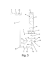
- the cutting path is in the form of a divergent cone, as seen in Figure 3
- the excess material from machining comes off by gravity
- the cutting path is in the form of a convergent cone, as in the case of Figures 1 and 2 , it is necessary to use blowers or other similar means to be able to separates the excess material from the workpiece (2).
- the beam rotator block (9) consists of a rectangular prism, such as a DOVE prism or an Abbe-Konig prism, although it can also be formed by a set of mirrors that can be rotated or inclined so that the first high-power laser beam (4) describes a circular path.
- the beam rotator block (9) consists of a galvanometric head formed by two mirrors (21, 22), each of which can be rotated about a respective axis of rotation (y, z), these axes of rotation (y, z) being substantially perpendicular to one another. Therefore, by controlling the rotation of the two mirrors (21, 22), the first high-power laser beam (4) can be guided according to a circular path, allowing making holes on the workpiece (2) by adjusting radius and taper.
- the focusing optical block (10) which is used for focusing the first high-power laser beam (4) onto the surface of the workpiece (2) is arranged at the outlet of the beam rotator block (9).
- a single lens is used for focusing the first high-power laser beam (4), although a set of lenses could be used.
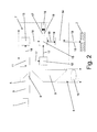
- the embodiment of Figure 2 shows the laser emission source (1) which has been regulated by the regulating means (3) to emit on the workpiece (2) the second low-power laser beam (5) which is used for inspecting the workpiece (2) once it has been machined, or for inspecting the piece at regular intervals during the machining cycle.
- the second guiding means (7) which are used for guiding the second low-power laser beam (5) consist of a digital holography system whereby three-dimensional topographic images of the workpiece (2) are obtained in the order of milliseconds.
- the second guiding means (7) comprise a power control and splitting block (11), optical adaptation blocks (12, 13, 14), a beam splitting block (15) and a receiving block (16).
- the power control and splitting block (11) is used for splitting the second low-power laser beam (5) emitted by the laser emission source (1) into two beams, i.e., a reference beam (17)n which is guided directly towards the receiving block (16)n and a target beam (18), which is used for illuminating the machined area of the workpiece (2).
- the power control and splitting block (11) is also used for adjusting the power required for each of the two beams (17, 18) into which the second low-power laser beam (5) is split.
- the power control and splitting block (11) can be formed by means of fiber components or by means of optical components, such as lenses, polarized films, or the like.
- First and second optical adaptation blocks (12, 13) are arranged at the outlet of the power control and splitting block (11), the first optical adaptation block (12) being used for guiding the reference beam (17), and the second optical adaptation block (13) being used for guiding the target beam (18) from the power control and splitting block (11) towards the beam splitting block (15).
- the first and second optical adaptation blocks (12, 13) are also used for adjusting the reference beam (17) and the target beam (18), respectively, according to the required dimensional characteristics.
- the beam splitting block (15) is a beam-splitter which allows the passage of the reference beam (17) so that it reaches the receiving block (16) directly, and allows the passage of the target beam (18) so that it illuminates the workpiece (2).
- a reflected target beam (19) which is guided towards the beam splitting block (15) is created, the latter allowing the reflected target beam (19) to be guided towards the receiving block (16).
- the third optical adaptation block (14) which allows focusing the target beam (18) on the workpiece (2) and illuminating it, is arranged between the beam splitting block (15) and the workpiece (2) to be inspected.
- the reference beam (17) and the reflected target beam (19) reach the receiving block (16), which has been envisaged to be a digital CCD or CMOS camera, these two beams (17, 19) interfering with one another to generate a holographic pattern which, by means of digital holography techniques, allows the topographical reconstruction of the machined area of the work surface (2), possible defects that may have been caused while machining the workpiece (2) by boring thus being determined.
- Another alternative option is to keep the first and second guiding means (6, 7) fixed and to move the workpiece (2) horizontally for being positioned below the first and second guiding means (6, 7), for which purpose the workpiece (2) can be mounted on a moving table having at least a horizontal translational movement in one axis.
- Figure 3 shows another embodiment of the invention in which the first guiding means (6) are arranged in an upper position with respect to the workpiece (2), and the second guiding means (7) are arranged in a lower position with respect to the workpiece (2).
- the workpiece (2) is therefore inspected from the lower part thereof, the need to have to move the first and second guiding means (6, 7) being prevented.
Landscapes
- Physics & Mathematics (AREA)
- Optics & Photonics (AREA)
- Engineering & Computer Science (AREA)
- General Physics & Mathematics (AREA)
- Plasma & Fusion (AREA)
- Mechanical Engineering (AREA)
- Laser Beam Processing (AREA)
Priority Applications (1)
| Application Number | Priority Date | Filing Date | Title |
|---|---|---|---|
| EP14380019.1A EP2962802B1 (fr) | 2014-07-04 | 2014-07-04 | Tête d'inspection et d'usinage laser |
Applications Claiming Priority (1)
| Application Number | Priority Date | Filing Date | Title |
|---|---|---|---|
| EP14380019.1A EP2962802B1 (fr) | 2014-07-04 | 2014-07-04 | Tête d'inspection et d'usinage laser |
Publications (2)
| Publication Number | Publication Date |
|---|---|
| EP2962802A1 true EP2962802A1 (fr) | 2016-01-06 |
| EP2962802B1 EP2962802B1 (fr) | 2017-03-01 |
Family
ID=51390078
Family Applications (1)
| Application Number | Title | Priority Date | Filing Date |
|---|---|---|---|
| EP14380019.1A Not-in-force EP2962802B1 (fr) | 2014-07-04 | 2014-07-04 | Tête d'inspection et d'usinage laser |
Country Status (1)
| Country | Link |
|---|---|
| EP (1) | EP2962802B1 (fr) |
Cited By (4)
| Publication number | Priority date | Publication date | Assignee | Title |
|---|---|---|---|---|
| WO2022188321A1 (fr) * | 2021-03-10 | 2022-09-15 | 武汉华工激光工程有限责任公司 | Système de découpe laser |
| CN115213568A (zh) * | 2021-03-31 | 2022-10-21 | 宁波大艾激光科技有限公司 | 一种复合激光加工系统及加工方法 |
| CN117697147A (zh) * | 2023-12-26 | 2024-03-15 | 南京英尼格玛工业自动化技术有限公司 | 窄间隙焊接系统 |
| CN119549870A (zh) * | 2024-12-10 | 2025-03-04 | 江苏昆仑精密科技有限公司 | 激光扫描加工系统及其控制方法 |
Citations (6)
| Publication number | Priority date | Publication date | Assignee | Title |
|---|---|---|---|---|
| US5339152A (en) * | 1992-04-24 | 1994-08-16 | Grumman Aerospace Corporation | Holographic inspection system with integral stress inducer |
| US6355907B1 (en) | 1997-09-18 | 2002-03-12 | Robert Bosch Gmbh | Optical device for boring using a laser beam |
| US6444948B1 (en) | 1997-10-15 | 2002-09-03 | Daimlerchrysler Ag | Fine and micro-machining process for workpieces by means of laser beams |
| US7842901B2 (en) | 2005-06-28 | 2010-11-30 | Fraunhofer-Gesellschaft zur Foerderung der Angwandten Foerschng E.V. | Device for drilling and for removing material using a laser beam |
| WO2012037694A2 (fr) * | 2010-09-25 | 2012-03-29 | Queen's University At Kingston | Procédés et systèmes d'imagerie cohérente et de commande par rétroaction permettant une modification de matériaux |
| US20130175243A1 (en) | 2012-01-11 | 2013-07-11 | The Ex One Company, Llc | Laser Drilling and Trepanning Device |
Family Cites Families (1)
| Publication number | Priority date | Publication date | Assignee | Title |
|---|---|---|---|---|
| DE102004053298B4 (de) * | 2004-08-26 | 2008-10-09 | ARGES Gesellschaft für Industrieplanung und Lasertechnik m.b.H. | Scankopf als Teil einer Laser Bohr- und Schneideinrichtung |
-
2014
- 2014-07-04 EP EP14380019.1A patent/EP2962802B1/fr not_active Not-in-force
Patent Citations (6)
| Publication number | Priority date | Publication date | Assignee | Title |
|---|---|---|---|---|
| US5339152A (en) * | 1992-04-24 | 1994-08-16 | Grumman Aerospace Corporation | Holographic inspection system with integral stress inducer |
| US6355907B1 (en) | 1997-09-18 | 2002-03-12 | Robert Bosch Gmbh | Optical device for boring using a laser beam |
| US6444948B1 (en) | 1997-10-15 | 2002-09-03 | Daimlerchrysler Ag | Fine and micro-machining process for workpieces by means of laser beams |
| US7842901B2 (en) | 2005-06-28 | 2010-11-30 | Fraunhofer-Gesellschaft zur Foerderung der Angwandten Foerschng E.V. | Device for drilling and for removing material using a laser beam |
| WO2012037694A2 (fr) * | 2010-09-25 | 2012-03-29 | Queen's University At Kingston | Procédés et systèmes d'imagerie cohérente et de commande par rétroaction permettant une modification de matériaux |
| US20130175243A1 (en) | 2012-01-11 | 2013-07-11 | The Ex One Company, Llc | Laser Drilling and Trepanning Device |
Cited By (4)
| Publication number | Priority date | Publication date | Assignee | Title |
|---|---|---|---|---|
| WO2022188321A1 (fr) * | 2021-03-10 | 2022-09-15 | 武汉华工激光工程有限责任公司 | Système de découpe laser |
| CN115213568A (zh) * | 2021-03-31 | 2022-10-21 | 宁波大艾激光科技有限公司 | 一种复合激光加工系统及加工方法 |
| CN117697147A (zh) * | 2023-12-26 | 2024-03-15 | 南京英尼格玛工业自动化技术有限公司 | 窄间隙焊接系统 |
| CN119549870A (zh) * | 2024-12-10 | 2025-03-04 | 江苏昆仑精密科技有限公司 | 激光扫描加工系统及其控制方法 |
Also Published As
| Publication number | Publication date |
|---|---|
| EP2962802B1 (fr) | 2017-03-01 |
Similar Documents
| Publication | Publication Date | Title |
|---|---|---|
| JP5519047B1 (ja) | 切削工具検査装置 | |
| JP3642969B2 (ja) | レーザー加工装置および方法 | |
| TWI686603B (zh) | 用於檢查襯底之檢查系統、襯底切割設備、檢查襯底之方法及襯底切割技術 | |
| EP2962802B1 (fr) | Tête d'inspection et d'usinage laser | |
| TW201434562A (zh) | 錐度控制之射束角協調及工件運動 | |
| US9983562B2 (en) | Adaptive part profile creation via independent side measurement with alignment features | |
| US20130193618A1 (en) | Laser Machining System and Method for Machining Three-Dimensional Objects from a Plurality of Directions | |
| KR102483670B1 (ko) | 레이저 가공 시스템 및 레이저 가공 방법 | |
| US20220097144A1 (en) | Laser printing device for creating 3d product and laser printing method for creating 3d product | |
| US11571767B2 (en) | Laser processing device and laser processing method | |
| KR20050091069A (ko) | 취성 재료 기판의 스크라이브 장치 및 스크라이브 방법그리고 자동 분단 라인 | |
| US9346122B1 (en) | Multi-wavelength laser processing systems and associated methods of use and manufacture | |
| CN105290622A (zh) | 一种可自适应切割的激光切割机及采用其进行激光切割的方法 | |
| KR101335039B1 (ko) | 레이저 가공 장치 및 레이저 가공 장치를 사용한 피가공물의 가공 방법 | |
| KR102100361B1 (ko) | 금속 마스크 생산 장치 | |
| CN111375913A (zh) | 激光加工装置及光束旋转器单元 | |
| CN113305422A (zh) | 一种同轴共焦激光加工系统 | |
| KR101245804B1 (ko) | 레이저 마킹 시스템 | |
| KR20080113876A (ko) | 피가공물의 홀 드릴링/다이싱 가공장치 및 가공방법 | |
| TWI587957B (zh) | 用於電路之一檢測/維修/檢測系統之透鏡總成及用於電路之一檢測/維修/檢測系統之組合器總成 | |
| WO2010005394A1 (fr) | Système et procédé de traitement au laser | |
| CN116038105A (zh) | 一种双振镜金刚石加工的装备 | |
| TW202247720A (zh) | 使用在修復期間感應及發射之光之光譜組件控制電子電路之雷射修復處理 | |
| KR100862620B1 (ko) | 컬러 필터 돌기 제거장치 및 제거방법 | |
| JP7744017B2 (ja) | ツインビーム半田付け装置 |
Legal Events
| Date | Code | Title | Description |
|---|---|---|---|
| PUAI | Public reference made under article 153(3) epc to a published international application that has entered the european phase |
Free format text: ORIGINAL CODE: 0009012 |
|
| AK | Designated contracting states |
Kind code of ref document: A1 Designated state(s): AL AT BE BG CH CY CZ DE DK EE ES FI FR GB GR HR HU IE IS IT LI LT LU LV MC MK MT NL NO PL PT RO RS SE SI SK SM TR |
|
| AX | Request for extension of the european patent |
Extension state: BA ME |
|
| 17P | Request for examination filed |
Effective date: 20160523 |
|
| RBV | Designated contracting states (corrected) |
Designated state(s): AL AT BE BG CH CY CZ DE DK EE ES FI FR GB GR HR HU IE IS IT LI LT LU LV MC MK MT NL NO PL PT RO RS SE SI SK SM TR |
|
| GRAP | Despatch of communication of intention to grant a patent |
Free format text: ORIGINAL CODE: EPIDOSNIGR1 |
|
| INTG | Intention to grant announced |
Effective date: 20160915 |
|
| STAA | Information on the status of an ep patent application or granted ep patent |
Free format text: STATUS: GRANT OF PATENT IS INTENDED |
|
| GRAS | Grant fee paid |
Free format text: ORIGINAL CODE: EPIDOSNIGR3 |
|
| GRAA | (expected) grant |
Free format text: ORIGINAL CODE: 0009210 |
|
| STAA | Information on the status of an ep patent application or granted ep patent |
Free format text: STATUS: THE PATENT HAS BEEN GRANTED |
|
| AK | Designated contracting states |
Kind code of ref document: B1 Designated state(s): AL AT BE BG CH CY CZ DE DK EE ES FI FR GB GR HR HU IE IS IT LI LT LU LV MC MK MT NL NO PL PT RO RS SE SI SK SM TR |
|
| REG | Reference to a national code |
Ref country code: GB Ref legal event code: FG4D |
|
| REG | Reference to a national code |
Ref country code: CH Ref legal event code: EP Ref country code: AT Ref legal event code: REF Ref document number: 870706 Country of ref document: AT Kind code of ref document: T Effective date: 20170315 |
|
| REG | Reference to a national code |
Ref country code: IE Ref legal event code: FG4D |
|
| REG | Reference to a national code |
Ref country code: DE Ref legal event code: R096 Ref document number: 602014007106 Country of ref document: DE |
|
| REG | Reference to a national code |
Ref country code: NL Ref legal event code: MP Effective date: 20170301 |
|
| REG | Reference to a national code |
Ref country code: LT Ref legal event code: MG4D |
|
| REG | Reference to a national code |
Ref country code: AT Ref legal event code: MK05 Ref document number: 870706 Country of ref document: AT Kind code of ref document: T Effective date: 20170301 |
|
| PG25 | Lapsed in a contracting state [announced via postgrant information from national office to epo] |
Ref country code: LT Free format text: LAPSE BECAUSE OF FAILURE TO SUBMIT A TRANSLATION OF THE DESCRIPTION OR TO PAY THE FEE WITHIN THE PRESCRIBED TIME-LIMIT Effective date: 20170301 Ref country code: NO Free format text: LAPSE BECAUSE OF FAILURE TO SUBMIT A TRANSLATION OF THE DESCRIPTION OR TO PAY THE FEE WITHIN THE PRESCRIBED TIME-LIMIT Effective date: 20170601 Ref country code: FI Free format text: LAPSE BECAUSE OF FAILURE TO SUBMIT A TRANSLATION OF THE DESCRIPTION OR TO PAY THE FEE WITHIN THE PRESCRIBED TIME-LIMIT Effective date: 20170301 Ref country code: GR Free format text: LAPSE BECAUSE OF FAILURE TO SUBMIT A TRANSLATION OF THE DESCRIPTION OR TO PAY THE FEE WITHIN THE PRESCRIBED TIME-LIMIT Effective date: 20170602 Ref country code: HR Free format text: LAPSE BECAUSE OF FAILURE TO SUBMIT A TRANSLATION OF THE DESCRIPTION OR TO PAY THE FEE WITHIN THE PRESCRIBED TIME-LIMIT Effective date: 20170301 |
|
| PG25 | Lapsed in a contracting state [announced via postgrant information from national office to epo] |
Ref country code: SE Free format text: LAPSE BECAUSE OF FAILURE TO SUBMIT A TRANSLATION OF THE DESCRIPTION OR TO PAY THE FEE WITHIN THE PRESCRIBED TIME-LIMIT Effective date: 20170301 Ref country code: AT Free format text: LAPSE BECAUSE OF FAILURE TO SUBMIT A TRANSLATION OF THE DESCRIPTION OR TO PAY THE FEE WITHIN THE PRESCRIBED TIME-LIMIT Effective date: 20170301 Ref country code: BG Free format text: LAPSE BECAUSE OF FAILURE TO SUBMIT A TRANSLATION OF THE DESCRIPTION OR TO PAY THE FEE WITHIN THE PRESCRIBED TIME-LIMIT Effective date: 20170601 Ref country code: RS Free format text: LAPSE BECAUSE OF FAILURE TO SUBMIT A TRANSLATION OF THE DESCRIPTION OR TO PAY THE FEE WITHIN THE PRESCRIBED TIME-LIMIT Effective date: 20170301 Ref country code: ES Free format text: LAPSE BECAUSE OF FAILURE TO SUBMIT A TRANSLATION OF THE DESCRIPTION OR TO PAY THE FEE WITHIN THE PRESCRIBED TIME-LIMIT Effective date: 20170301 Ref country code: LV Free format text: LAPSE BECAUSE OF FAILURE TO SUBMIT A TRANSLATION OF THE DESCRIPTION OR TO PAY THE FEE WITHIN THE PRESCRIBED TIME-LIMIT Effective date: 20170301 |
|
| PG25 | Lapsed in a contracting state [announced via postgrant information from national office to epo] |
Ref country code: NL Free format text: LAPSE BECAUSE OF FAILURE TO SUBMIT A TRANSLATION OF THE DESCRIPTION OR TO PAY THE FEE WITHIN THE PRESCRIBED TIME-LIMIT Effective date: 20170301 |
|
| PG25 | Lapsed in a contracting state [announced via postgrant information from national office to epo] |
Ref country code: CZ Free format text: LAPSE BECAUSE OF FAILURE TO SUBMIT A TRANSLATION OF THE DESCRIPTION OR TO PAY THE FEE WITHIN THE PRESCRIBED TIME-LIMIT Effective date: 20170301 Ref country code: IT Free format text: LAPSE BECAUSE OF FAILURE TO SUBMIT A TRANSLATION OF THE DESCRIPTION OR TO PAY THE FEE WITHIN THE PRESCRIBED TIME-LIMIT Effective date: 20170301 Ref country code: SK Free format text: LAPSE BECAUSE OF FAILURE TO SUBMIT A TRANSLATION OF THE DESCRIPTION OR TO PAY THE FEE WITHIN THE PRESCRIBED TIME-LIMIT Effective date: 20170301 Ref country code: EE Free format text: LAPSE BECAUSE OF FAILURE TO SUBMIT A TRANSLATION OF THE DESCRIPTION OR TO PAY THE FEE WITHIN THE PRESCRIBED TIME-LIMIT Effective date: 20170301 Ref country code: RO Free format text: LAPSE BECAUSE OF FAILURE TO SUBMIT A TRANSLATION OF THE DESCRIPTION OR TO PAY THE FEE WITHIN THE PRESCRIBED TIME-LIMIT Effective date: 20170301 |
|
| PG25 | Lapsed in a contracting state [announced via postgrant information from national office to epo] |
Ref country code: IS Free format text: LAPSE BECAUSE OF FAILURE TO SUBMIT A TRANSLATION OF THE DESCRIPTION OR TO PAY THE FEE WITHIN THE PRESCRIBED TIME-LIMIT Effective date: 20170701 Ref country code: PT Free format text: LAPSE BECAUSE OF FAILURE TO SUBMIT A TRANSLATION OF THE DESCRIPTION OR TO PAY THE FEE WITHIN THE PRESCRIBED TIME-LIMIT Effective date: 20170703 Ref country code: SM Free format text: LAPSE BECAUSE OF FAILURE TO SUBMIT A TRANSLATION OF THE DESCRIPTION OR TO PAY THE FEE WITHIN THE PRESCRIBED TIME-LIMIT Effective date: 20170301 Ref country code: PL Free format text: LAPSE BECAUSE OF FAILURE TO SUBMIT A TRANSLATION OF THE DESCRIPTION OR TO PAY THE FEE WITHIN THE PRESCRIBED TIME-LIMIT Effective date: 20170301 |
|
| REG | Reference to a national code |
Ref country code: DE Ref legal event code: R097 Ref document number: 602014007106 Country of ref document: DE |
|
| PLBE | No opposition filed within time limit |
Free format text: ORIGINAL CODE: 0009261 |
|
| STAA | Information on the status of an ep patent application or granted ep patent |
Free format text: STATUS: NO OPPOSITION FILED WITHIN TIME LIMIT |
|
| PG25 | Lapsed in a contracting state [announced via postgrant information from national office to epo] |
Ref country code: DK Free format text: LAPSE BECAUSE OF FAILURE TO SUBMIT A TRANSLATION OF THE DESCRIPTION OR TO PAY THE FEE WITHIN THE PRESCRIBED TIME-LIMIT Effective date: 20170301 |
|
| REG | Reference to a national code |
Ref country code: DE Ref legal event code: R119 Ref document number: 602014007106 Country of ref document: DE |
|
| 26N | No opposition filed |
Effective date: 20171204 |
|
| PG25 | Lapsed in a contracting state [announced via postgrant information from national office to epo] |
Ref country code: SI Free format text: LAPSE BECAUSE OF FAILURE TO SUBMIT A TRANSLATION OF THE DESCRIPTION OR TO PAY THE FEE WITHIN THE PRESCRIBED TIME-LIMIT Effective date: 20170301 |
|
| REG | Reference to a national code |
Ref country code: CH Ref legal event code: PL |
|
| REG | Reference to a national code |
Ref country code: IE Ref legal event code: MM4A |
|
| REG | Reference to a national code |
Ref country code: FR Ref legal event code: ST Effective date: 20180330 |
|
| PG25 | Lapsed in a contracting state [announced via postgrant information from national office to epo] |
Ref country code: LI Free format text: LAPSE BECAUSE OF NON-PAYMENT OF DUE FEES Effective date: 20170731 Ref country code: IE Free format text: LAPSE BECAUSE OF NON-PAYMENT OF DUE FEES Effective date: 20170704 Ref country code: CH Free format text: LAPSE BECAUSE OF NON-PAYMENT OF DUE FEES Effective date: 20170731 Ref country code: DE Free format text: LAPSE BECAUSE OF NON-PAYMENT OF DUE FEES Effective date: 20180201 |
|
| PG25 | Lapsed in a contracting state [announced via postgrant information from national office to epo] |
Ref country code: FR Free format text: LAPSE BECAUSE OF NON-PAYMENT OF DUE FEES Effective date: 20170731 |
|
| REG | Reference to a national code |
Ref country code: BE Ref legal event code: MM Effective date: 20170731 |
|
| PG25 | Lapsed in a contracting state [announced via postgrant information from national office to epo] |
Ref country code: LU Free format text: LAPSE BECAUSE OF NON-PAYMENT OF DUE FEES Effective date: 20170704 |
|
| PG25 | Lapsed in a contracting state [announced via postgrant information from national office to epo] |
Ref country code: BE Free format text: LAPSE BECAUSE OF NON-PAYMENT OF DUE FEES Effective date: 20170731 |
|
| PG25 | Lapsed in a contracting state [announced via postgrant information from national office to epo] |
Ref country code: MT Free format text: LAPSE BECAUSE OF NON-PAYMENT OF DUE FEES Effective date: 20170704 |
|
| GBPC | Gb: european patent ceased through non-payment of renewal fee |
Effective date: 20180704 |
|
| PG25 | Lapsed in a contracting state [announced via postgrant information from national office to epo] |
Ref country code: GB Free format text: LAPSE BECAUSE OF NON-PAYMENT OF DUE FEES Effective date: 20180704 |
|
| PG25 | Lapsed in a contracting state [announced via postgrant information from national office to epo] |
Ref country code: MC Free format text: LAPSE BECAUSE OF FAILURE TO SUBMIT A TRANSLATION OF THE DESCRIPTION OR TO PAY THE FEE WITHIN THE PRESCRIBED TIME-LIMIT Effective date: 20170301 Ref country code: HU Free format text: LAPSE BECAUSE OF FAILURE TO SUBMIT A TRANSLATION OF THE DESCRIPTION OR TO PAY THE FEE WITHIN THE PRESCRIBED TIME-LIMIT; INVALID AB INITIO Effective date: 20140704 |
|
| PG25 | Lapsed in a contracting state [announced via postgrant information from national office to epo] |
Ref country code: CY Free format text: LAPSE BECAUSE OF FAILURE TO SUBMIT A TRANSLATION OF THE DESCRIPTION OR TO PAY THE FEE WITHIN THE PRESCRIBED TIME-LIMIT Effective date: 20170301 |
|
| PG25 | Lapsed in a contracting state [announced via postgrant information from national office to epo] |
Ref country code: MK Free format text: LAPSE BECAUSE OF FAILURE TO SUBMIT A TRANSLATION OF THE DESCRIPTION OR TO PAY THE FEE WITHIN THE PRESCRIBED TIME-LIMIT Effective date: 20170301 |
|
| PG25 | Lapsed in a contracting state [announced via postgrant information from national office to epo] |
Ref country code: TR Free format text: LAPSE BECAUSE OF FAILURE TO SUBMIT A TRANSLATION OF THE DESCRIPTION OR TO PAY THE FEE WITHIN THE PRESCRIBED TIME-LIMIT Effective date: 20170301 |
|
| PG25 | Lapsed in a contracting state [announced via postgrant information from national office to epo] |
Ref country code: AL Free format text: LAPSE BECAUSE OF FAILURE TO SUBMIT A TRANSLATION OF THE DESCRIPTION OR TO PAY THE FEE WITHIN THE PRESCRIBED TIME-LIMIT Effective date: 20170301 |