EP2963147A2 - Dispositif de generation d'une vapeur a partir d'une matiere de depart liquide ou solide pour un dispositif en cvd ou pvd - Google Patents
Dispositif de generation d'une vapeur a partir d'une matiere de depart liquide ou solide pour un dispositif en cvd ou pvd Download PDFInfo
- Publication number
- EP2963147A2 EP2963147A2 EP15173776.4A EP15173776A EP2963147A2 EP 2963147 A2 EP2963147 A2 EP 2963147A2 EP 15173776 A EP15173776 A EP 15173776A EP 2963147 A2 EP2963147 A2 EP 2963147A2
- Authority
- EP
- European Patent Office
- Prior art keywords
- heat transfer
- transfer body
- aerosol
- flow channel
- supply pipe
- Prior art date
- Legal status (The legal status is an assumption and is not a legal conclusion. Google has not performed a legal analysis and makes no representation as to the accuracy of the status listed.)
- Granted
Links
Images



Classifications
-
- H—ELECTRICITY
- H05—ELECTRIC TECHNIQUES NOT OTHERWISE PROVIDED FOR
- H05B—ELECTRIC HEATING; ELECTRIC LIGHT SOURCES NOT OTHERWISE PROVIDED FOR; CIRCUIT ARRANGEMENTS FOR ELECTRIC LIGHT SOURCES, IN GENERAL
- H05B3/00—Ohmic-resistance heating
- H05B3/0014—Devices wherein the heating current flows through particular resistances
-
- C—CHEMISTRY; METALLURGY
- C23—COATING METALLIC MATERIAL; COATING MATERIAL WITH METALLIC MATERIAL; CHEMICAL SURFACE TREATMENT; DIFFUSION TREATMENT OF METALLIC MATERIAL; COATING BY VACUUM EVAPORATION, BY SPUTTERING, BY ION IMPLANTATION OR BY CHEMICAL VAPOUR DEPOSITION, IN GENERAL; INHIBITING CORROSION OF METALLIC MATERIAL OR INCRUSTATION IN GENERAL
- C23C—COATING METALLIC MATERIAL; COATING MATERIAL WITH METALLIC MATERIAL; SURFACE TREATMENT OF METALLIC MATERIAL BY DIFFUSION INTO THE SURFACE, BY CHEMICAL CONVERSION OR SUBSTITUTION; COATING BY VACUUM EVAPORATION, BY SPUTTERING, BY ION IMPLANTATION OR BY CHEMICAL VAPOUR DEPOSITION, IN GENERAL
- C23C14/00—Coating by vacuum evaporation, by sputtering or by ion implantation of the coating forming material
- C23C14/06—Coating by vacuum evaporation, by sputtering or by ion implantation of the coating forming material characterised by the coating material
- C23C14/12—Organic material
-
- C—CHEMISTRY; METALLURGY
- C23—COATING METALLIC MATERIAL; COATING MATERIAL WITH METALLIC MATERIAL; CHEMICAL SURFACE TREATMENT; DIFFUSION TREATMENT OF METALLIC MATERIAL; COATING BY VACUUM EVAPORATION, BY SPUTTERING, BY ION IMPLANTATION OR BY CHEMICAL VAPOUR DEPOSITION, IN GENERAL; INHIBITING CORROSION OF METALLIC MATERIAL OR INCRUSTATION IN GENERAL
- C23C—COATING METALLIC MATERIAL; COATING MATERIAL WITH METALLIC MATERIAL; SURFACE TREATMENT OF METALLIC MATERIAL BY DIFFUSION INTO THE SURFACE, BY CHEMICAL CONVERSION OR SUBSTITUTION; COATING BY VACUUM EVAPORATION, BY SPUTTERING, BY ION IMPLANTATION OR BY CHEMICAL VAPOUR DEPOSITION, IN GENERAL
- C23C14/00—Coating by vacuum evaporation, by sputtering or by ion implantation of the coating forming material
- C23C14/22—Coating by vacuum evaporation, by sputtering or by ion implantation of the coating forming material characterised by the process of coating
- C23C14/24—Vacuum evaporation
- C23C14/246—Replenishment of source material
-
- C—CHEMISTRY; METALLURGY
- C23—COATING METALLIC MATERIAL; COATING MATERIAL WITH METALLIC MATERIAL; CHEMICAL SURFACE TREATMENT; DIFFUSION TREATMENT OF METALLIC MATERIAL; COATING BY VACUUM EVAPORATION, BY SPUTTERING, BY ION IMPLANTATION OR BY CHEMICAL VAPOUR DEPOSITION, IN GENERAL; INHIBITING CORROSION OF METALLIC MATERIAL OR INCRUSTATION IN GENERAL
- C23C—COATING METALLIC MATERIAL; COATING MATERIAL WITH METALLIC MATERIAL; SURFACE TREATMENT OF METALLIC MATERIAL BY DIFFUSION INTO THE SURFACE, BY CHEMICAL CONVERSION OR SUBSTITUTION; COATING BY VACUUM EVAPORATION, BY SPUTTERING, BY ION IMPLANTATION OR BY CHEMICAL VAPOUR DEPOSITION, IN GENERAL
- C23C14/00—Coating by vacuum evaporation, by sputtering or by ion implantation of the coating forming material
- C23C14/22—Coating by vacuum evaporation, by sputtering or by ion implantation of the coating forming material characterised by the process of coating
- C23C14/24—Vacuum evaporation
- C23C14/26—Vacuum evaporation by resistance or inductive heating of the source
-
- C—CHEMISTRY; METALLURGY
- C23—COATING METALLIC MATERIAL; COATING MATERIAL WITH METALLIC MATERIAL; CHEMICAL SURFACE TREATMENT; DIFFUSION TREATMENT OF METALLIC MATERIAL; COATING BY VACUUM EVAPORATION, BY SPUTTERING, BY ION IMPLANTATION OR BY CHEMICAL VAPOUR DEPOSITION, IN GENERAL; INHIBITING CORROSION OF METALLIC MATERIAL OR INCRUSTATION IN GENERAL
- C23C—COATING METALLIC MATERIAL; COATING MATERIAL WITH METALLIC MATERIAL; SURFACE TREATMENT OF METALLIC MATERIAL BY DIFFUSION INTO THE SURFACE, BY CHEMICAL CONVERSION OR SUBSTITUTION; COATING BY VACUUM EVAPORATION, BY SPUTTERING, BY ION IMPLANTATION OR BY CHEMICAL VAPOUR DEPOSITION, IN GENERAL
- C23C16/00—Chemical coating by decomposition of gaseous compounds, without leaving reaction products of surface material in the coating, i.e. chemical vapour deposition [CVD] processes
- C23C16/44—Chemical coating by decomposition of gaseous compounds, without leaving reaction products of surface material in the coating, i.e. chemical vapour deposition [CVD] processes characterised by the method of coating
- C23C16/448—Chemical coating by decomposition of gaseous compounds, without leaving reaction products of surface material in the coating, i.e. chemical vapour deposition [CVD] processes characterised by the method of coating characterised by the method used for generating reactive gas streams, e.g. by evaporation or sublimation of precursor materials
- C23C16/4481—Chemical coating by decomposition of gaseous compounds, without leaving reaction products of surface material in the coating, i.e. chemical vapour deposition [CVD] processes characterised by the method of coating characterised by the method used for generating reactive gas streams, e.g. by evaporation or sublimation of precursor materials by evaporation using carrier gas in contact with the source material
- C23C16/4483—Chemical coating by decomposition of gaseous compounds, without leaving reaction products of surface material in the coating, i.e. chemical vapour deposition [CVD] processes characterised by the method of coating characterised by the method used for generating reactive gas streams, e.g. by evaporation or sublimation of precursor materials by evaporation using carrier gas in contact with the source material using a porous body
-
- C—CHEMISTRY; METALLURGY
- C23—COATING METALLIC MATERIAL; COATING MATERIAL WITH METALLIC MATERIAL; CHEMICAL SURFACE TREATMENT; DIFFUSION TREATMENT OF METALLIC MATERIAL; COATING BY VACUUM EVAPORATION, BY SPUTTERING, BY ION IMPLANTATION OR BY CHEMICAL VAPOUR DEPOSITION, IN GENERAL; INHIBITING CORROSION OF METALLIC MATERIAL OR INCRUSTATION IN GENERAL
- C23C—COATING METALLIC MATERIAL; COATING MATERIAL WITH METALLIC MATERIAL; SURFACE TREATMENT OF METALLIC MATERIAL BY DIFFUSION INTO THE SURFACE, BY CHEMICAL CONVERSION OR SUBSTITUTION; COATING BY VACUUM EVAPORATION, BY SPUTTERING, BY ION IMPLANTATION OR BY CHEMICAL VAPOUR DEPOSITION, IN GENERAL
- C23C16/00—Chemical coating by decomposition of gaseous compounds, without leaving reaction products of surface material in the coating, i.e. chemical vapour deposition [CVD] processes
- C23C16/44—Chemical coating by decomposition of gaseous compounds, without leaving reaction products of surface material in the coating, i.e. chemical vapour deposition [CVD] processes characterised by the method of coating
- C23C16/455—Chemical coating by decomposition of gaseous compounds, without leaving reaction products of surface material in the coating, i.e. chemical vapour deposition [CVD] processes characterised by the method of coating characterised by the method used for introducing gases into reaction chamber or for modifying gas flows in reaction chamber
- C23C16/45563—Gas nozzles
- C23C16/45565—Shower nozzles
-
- H—ELECTRICITY
- H05—ELECTRIC TECHNIQUES NOT OTHERWISE PROVIDED FOR
- H05B—ELECTRIC HEATING; ELECTRIC LIGHT SOURCES NOT OTHERWISE PROVIDED FOR; CIRCUIT ARRANGEMENTS FOR ELECTRIC LIGHT SOURCES, IN GENERAL
- H05B3/00—Ohmic-resistance heating
- H05B3/02—Details
- H05B3/06—Heater elements structurally combined with coupling elements or holders
Definitions
- the invention relates to a device for generating a vapor for a CVD or PVD device having at least two arranged in the flow direction of a carrier gas, heat transfer surfaces having heat transfer bodies, each heatable to a heat transfer temperature, with a supply pipe for supplying an aerosol to one of the heat transfer body to evaporate the aerosol by contacting the aerosol particles with the heat transfer surfaces.
- the invention further relates to a device for generating a vapor for a CVD or PVD device having at least one heat transfer body, which can be heated to a heat transfer temperature and with a supply pipe for supplying an aerosol to the heat transfer body for evaporation of the aerosol by Contacting the aerosol particles with the heat transfer surfaces.
- the DE 10 2011 051 260 A1 describes a device for generating a vapor.
- a housing a plurality of, each having different cross-sections heat transfer body arranged in the flow direction one behind the other.
- a feed pipe for feeding an aerosol projects through an upstream heat transfer body and opens into a central cavity of the device.
- WO 2012/175128 A1 is in a housing a CVD or a PVD device, an evaporation device, having two successively arranged in the flow direction of an aerosol heat transfer body.
- the two heat transfer bodies are formed by electrically conductive solid-state foams, which are heated by passing an electric current.
- an aerosol is introduced into the evaporator.
- the aerosol particles come into contact with the heat transfer surfaces of the heat transfer bodies, so that the particles are evaporated.
- Similar devices are in the WO 2012/175124 A1 .
- WO 2010/175126 A1 such as DE 10 2011 051 261 A1 described.
- OLED light-emitting diodes
- organic starting materials For the production of these OLEDs solid or liquid starting materials must be brought into a gaseous form. This is done with an evaporator.
- the gasified starting material is passed as steam into a process chamber of a CVD or PVD reactor, where the vapor condenses on a substrate.
- the starting materials used for depositing OLEDs may only be exposed to a maximum evaporation temperature, since they are already decomposed at relatively low temperatures. This chemical decomposition temperature should not or should only be achieved for a very short time.
- the invention has for its object to improve a generic evaporator process technology.
- one of the heat transfer bodies has an opening in which a supply pipe is inserted.
- the supply pipe has an orifice through which an aerosol can be fed into the housing in such a way that the aerosol particles evaporate by being brought into contact with the heat transfer surfaces.
- the mouth of the supply pipe is arranged downstream of the mouth of the carrier gas supply line in the housing such that the carrier gas is first preheated in a preheater before it mixes with the vaporized aerosol.
- the mouth of the supply line therefore lies downstream of an upstream region of the preheating body, through which the carrier gas flows. According to this embodiment, it is also possible hineinzustecken the supply pipe against the flow direction of the carrier gas in an opening of the heat transfer body.
- the mouth of the supply line is then located in the upstream region of the heat transfer body or in a space between the heat transfer body having the opening and a heat transfer body disposed upstream of this heat transfer body.
- the opening is associated with an upstream heat transfer body and the mouth of the supply pipe is arranged in the flow direction before or in a downstream heat transfer body.
- the one or more feed pipes open into a space between two heat transfer bodies, so that the aerosol emerging from the mouth of the at least one feed pipe can enter the downstream heat transfer body over as large an area as possible.
- the first in the flow direction and thus upstream heat transfer body may be a preheater for a carrier gas.
- This first heat transfer body may have the opening through which the supply line for supplying an aerosol engages.
- the feed line opens either directly in a downstream heat transfer body or in a distance space upstream of the downstream heat transfer body. According to this embodiment, it is ensured that only the carrier gas, which is preheated, flows through the upstream heat transfer body.
- the aerosol is fed into the downstream heat transfer body, so that the aerosol particles can come into contact with the heat transfer surfaces of the heat transfer body. There, the heat of vaporization is transferred to the particles, so that the solid or liquid aerosol particles are brought into the gaseous form.
- a plurality of heat transfer bodies each of which exerts an evaporation function, are arranged in cascade fashion one behind the other.
- a downstream heat transfer body having the function of a vaporization body, one or more openings through which a feed line is inserted, which open into a relation to this heat transfer body downstream space or in a downstream heat transfer body.
- a first aerosol is vaporized in an upstream evaporator body and a second aerosol is evaporated in a downstream evaporator body.
- the two aerosols can be evaporated at different evaporation temperatures.
- the low vaporization temperature aerosol is fed to an upstream evaporator body and the high vaporization temperature aerosol is fed to a downstream evaporator body.
- the downstream evaporation body then has a higher heat transfer temperature than the heat transfer temperature of the upstream evaporation body.
- three or more heat transfer bodies may be arranged one behind the other in the flow direction, wherein the first heat transfer body in the flow direction serves only for heating a carrier gas and the plurality of downstream heat transfer bodies each for heating an aerosol and used to evaporate the aerosol.
- the aerosol evaporated in an upstream evaporation body passes as vapor the downstream evaporation body into which another aerosol is fed through a feed line.
- the evaporation body are preferably made of the material, as in the WO 2012/175128 A1 is described. It is an open-celled solid state foam with a porosity of 400 to 100 pores per inch.
- the evaporation body is electrically conductive, so that it can be heated by passing an electric current to its vaporization temperature.
- the supply pipes can be made of electrically insulated material or of metal. If the supply pipes are made of metal, they are surrounded in the region of the openings by an electrically insulating sleeve.
- the heat transfer bodies are located in a housing. They extend over the entire housing cross-sectional area, so that the carrier gas fed into the housing upstream must flow through all the heat transfer bodies arranged one behind the other.
- the aerosol or the vapor generated from the aerosol flows through at least the last heat transfer body in the flow direction.
- the vapor exit surface of the last heat transfer body may be a gas inlet surface through which the carrier gas and the vaporized aerosols transported by the carrier gas are introduced into a process chamber.
- the process chamber of the CVD PVD reactor is thus located in the flow direction immediately below the last heat transfer body in the flow direction. Through the gas outlet surface of this heat transfer body, a substantially homogeneous gas flow enters the process chamber.
- a substrate At the bottom of the process chamber is a substrate, on which the steam should condense.
- the susceptor carrying the substrate is preferably cooled by a cooling device.
- a second aspect of the invention relates to a non-return valve, which is arranged in the flow direction in front of the first heat transfer body.
- the backflow lock is thus located between the carrier gas supply line and the first heat transfer body.
- the non-return valve preferably consists of two plate-shaped bodies which extend over the entire cross-sectional area of the housing of the evaporator.
- the two plates have openings through which the carrier gas can flow.
- the openings of the two plates are offset from each other so that the carrier gas must first pass through the openings of the upstream backflow barrier plate, then is deflected into a gap to subsequently ⁇ end flow through the openings of the second backflow barrier plate.
- the invention also relates to the development of a supply pipe.
- the feed pipe according to the invention has means by which the gas stream emerging from the mouth of the feed pipe is widened so that the gas stream can enter the heat transfer body over as large an area as possible.
- a feed pipe developed according to the invention preferably discharges into a gap between two heat transfer bodies. But it may also open upstream of a heat transfer body in a volume portion of a housing.
- the supply pipe preferably has two flow channels, wherein a first flow channel for the passage of the aerosol and a second flow channel for feeding a carrier gas through openings in the first flow channel is provided. By the opening through the passage opening into the first flow channel carrier gas, the flow within the influenced first flow channel.
- the first flow channel preferably has a cross-sectional area which is greater than the cross-sectional area of the second flow channel.
- first gas passage openings are provided, which open into the first flow channel at an acute angle to the extension direction of the first flow channel or to the flow direction of the aerosol.
- second gas passage openings which are arranged downstream of the first gas passage openings in particular in the flow direction and particularly preferably in the region of the mouth of the supply pipe. With these second gas passage openings a twist is to be generated.
- the second gas passage openings not only open at an acute angle to the extension direction of the first flow channel, ie to the flow direction of the aerosol in the first flow channel. Rather, the second gas passage openings are also aligned obliquely with respect to a cross-sectional plane through the flow channel, so that it is fed into the first flow channel in a clockwise or counterclockwise rotating carrier gas flow. This creates a vortex. The associated centrifugal forces cause a widening of the emerging from the mouth of the supply gas flow.
- the two flow channels are formed from two nested tubes, so that the flow channels are arranged coaxially with each other, wherein the aerosol flows through the inner flow channel.
- the tube forming the first flow channel has a widening at its mouth, so that the cross-sectional area of the first flow channel increases continuously in the flow direction to the end of the feed tube. This also leads to a widening of the gas stream emerging from the mouth.
- the supply pipe has a central flow passage through which the aerosol flows. This flow channel is surrounded by a wall. This wall is preferably cooled. For this purpose, means are provided for cooling the wall of the flow channel. It may be a flow channel in which a cold coolant is fed.
- the coolant can be a carrier gas which flows through the previously described opening from a radially outer flow channel into a radially inner flow channel.
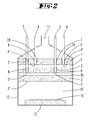
- the devices shown only schematically in the drawings are used for depositing OLED layers on substrates 14, which lie on a cooled susceptor 13 on a process chamber 15.
- a process gas generated from vaporized aerosols is fed.
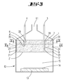
- the heat transfer body 1, 2, 3 extend over the entire cross-sectional area of the evaporator housing 12 and are arranged one behind the other in the flow direction.
- An uppermost arranged in the flow direction heat transfer body 1 forms in the embodiments, a preheater for preheating the carrier gas.
- the preheating of the carrier gas takes place outside of the evaporator housing 12, so that the first in the flow direction of the carrier gas within the evaporator housing 12 arranged heat transfer body is an evaporation body for one of the aerosols.
- evaporation body 2, 3 There are two successively arranged in the flow direction evaporation body 2, 3 are provided, which lie downstream of the preheater 1 in all embodiments.
- supply lines 4, 5 different aerosols are fed into the evaporation body 2, 3 from each other. This is done by evaporating a first aerosol having a low evaporation temperature in an upstream evaporator body 2 through the supply pipe 4, and feeding a second aerosol having a higher evaporating temperature into a second evaporator body 3 located downstream of the first evaporator body 3 becomes.
- the preheater 1 and the two evaporator bodies 2, 3 arranged downstream of it are each formed by a heat transfer body.
- the heat transfer body 1, 2, 3 consist of a solid state foam.
- the solid state foam has open cells and a porosity in the range between 400 and 100 pores per inch.
- the feeding of the aerosols is carried out according to the invention by tubular supply lines 4, 5, the openings 6, 7, 8 of heat transfer bodies 1, 2, 3 protrude or in openings 6, 8 of the heat transfer body 2, 3 are inserted.
- the openings preferably extend in the flow direction of the carrier gas, wherein the supply pipes are then inserted into the opening 6, 7, 8 either in the flow direction or counter to the flow direction.
- only one evaporation body 2 is provided. This is located together with a preheater 1 for the carrier gas in the housing 12 of the evaporation device.
- the preheater 1, that is, the upstream heat transfer body 1 is spaced from the downstream heat transfer body 2, that is, an evaporation body in the flow direction. It thus forms a distance space 9 between the two heat transfer bodies 1, 2, from. In this distance space 9 open the mouths 4 'of supply pipes 4, which extend in the flow direction of the carrier gas 11 extending openings 6 of the heat transfer body 1.
- the inner diameter of the openings 6 corresponds to the outer diameter of the supply pipes 4, so that the supply pipes 4 contact touching the inner wall of the opening 6.
- an aerosol is fed into the distance space 9.
- the aerosol, together with the carrier gas preheated by passing through the preheater 1, is introduced into the second heat transfer body 2 transported. There, the particles of the aerosol come in touching contact with the heat transfer surfaces of the heat transfer body 2.
- the particles of the aerosol heat of vaporization is supplied so that emerges from the gas outlet surface of the heat transfer body 2, a vaporized aerosol together with the carrier gas.
- the heat is supplied by electricity.
- the vapor and the carrier gas pass out of the evaporator 12 through a gas outlet opening 22 and into a gas inlet element 16 of a CVD reactor 17.
- the carrier gas and the vaporized aerosol enter the process chamber 15 through gas outlet openings of the gas inlet element 16.
- the supply pipes 4 are made of metal and are insulated by means of insulating sleeves 28 relative to the heat transfer body 1.
- a further heat transfer body 3 is disposed below the heat transfer body 2. Between the heat transfer body 2 and the heat transfer body 3, a second clearance space 10 is formed.
- the supply pipes 5 are inserted into openings 7 of the heat transfer body 1 and openings 8 of the heat transfer body 2. The second aerosol is thus passed through the supply pipe 5 through both heat transfer body 1 and 2 ,
- the heat transfer bodies 2, 3 can also be operated at the same heat transfer temperature.
- the downstream heat transfer body 3 preferably has a higher heat transfer temperature than the upstream heat transfer body 2 or the preheater 1. This makes it possible to evaporate a second aerosol in the heat transfer body 3, which has a higher evaporation temperature than the first aerosol, which is supplied through leads 4 is fed into the space 9 and in the heat transfer body 2.
- the gas outlet surface 3 'of the last heat transfer body 3 in the flow direction forms a feed surface through which the vaporized aerosol enters the process chamber 15 together with the carrier gas.
- the mouth 4 'of the supply pipe 4 is located in an upstream portion of the first evaporation body 2.
- the second supply pipe 5 penetrates as well as the first supply pipe 4 an opening of the first heat transfer body 1 in the flow direction and additionally an opening 8 of the second heat transfer body in the flow direction 2, so that the mouth 5 'of the supply pipe 5 opens into an upstream portion of the third heat transfer body 3.
- the supply of the evaporation energy takes place by supplying electric current.
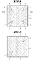
- the heat transfer body 1, 2, 3 electrical contact surfaces 20, 21 are associated with opposite narrow side walls of the heat transfer body 1, 2, 3.
- the two plate-shaped backflow blocking plates 18,19 are formed.
- the two return flow blocking plates 18, 19 are located in the flow direction between the feed opening 11 for feeding in the carrier gas and the first heat transfer body 1 in the flow direction.
- the return flow blocking plates 18, 19 are penetrated by the supply pipes 4, 5. You have appropriate openings for this purpose.
- Means to the return flow blocking plates 18,19 are openings 18 'of the return flow blocking plate 18 and openings 19' of the return flow blocking plate 19.
- the openings 18 'and 19' are offset in the flow direction to each other, so that a from the Staugaszu Arthur 11 entering the housing 12 carrier gas first must pass through the openings 18 'of the upstream backflow barrier plate 18, then be deflected into a clearance space between the two return flow blocking plates 18,19, to then exit through the openings 19' of the downstream return flow blocking plate 19.
- the backflow blocking plate assembly is intended to prevent vapor from a generated aerosol escaping from the upstream surface of the heat transfer bodies from entering the upper portion of the evaporation housing 12.
- the supply of aerosols is not by in the flow direction of the carrier gas in the heat transfer body 1, 2 inserted supply pipes 4, 5, but by supply pipes 4, 5, against the flow direction of the carrier gas in openings 6, 7, 8 of the heat transfer body 2, 3 are inserted.
- the supply of the supply pipes 4, 5 takes place in a sense from below.
- the supply pipe 4, through which the first aerosol opens into the intermediate space 9 between the preheater 1 and the first evaporation body 2, thus penetrates openings 7, 6 of both evaporation body 2, 3.
- the outer walls of the supply pipes 4, 5 or the outer walls of the supply pipes 4, 5 surrounding insulating sleeve 28 in contact with the inner wall of the respective opening 6, 7, 8 of the respective heat transfer body 1, 2, 3 at.
- FIG. 8 illustrated sixth embodiment shows an evaporation device 12, in which three heat transfer bodies 1, 2, 3 similar to those in the FIG. 3 represented third embodiment in the flow direction of the carrier gas are arranged directly behind one another.
- this embodiment has the above-described reverse current blocking plate assembly 18,19.
- the mouth 4 'of the supply pipe 4 opens here in the arranged below the preheating 1 first evaporation body 2, directly below the upper edge.
- the mouth 5 'of the supply line 5 is located immediately below the upper edge of the second evaporation body 3.
- the supply pipe 5 is inserted into an opening 8 of the evaporation body 3.
- the supply pipe 4 is inserted into an opening 6 of the evaporation body 2 and penetrates an opening 7 of the evaporation body third
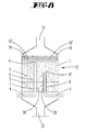
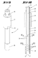
- the supply pipe 4 consists of two concentric nested tubes 33, 34, wherein the upper and lower edge of the inner tube 33 is gas-tightly connected to the upper and lower edges of the outer tube 34.
- the tube opening of the inner tube 33 forms a first flow channel 23, through which an aerosol can be passed, which is fed through an axial feed opening 25 in the first flow channel 23.
- the inner tube 33 is widened radially outward in the region of the mouth 4 'of the feed pipe 4.
- the mouth-side end portion of the outer tube 34 is surrounded by a sleeve 28 made of insulating material.
- the tubes 33, 34 themselves are made of metal, especially stainless steel.
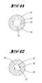
- the outer tube 34 has a total of four radial feed openings 26, through which a carrier gas can be fed into the flow channel 24, which is located between the inner tube 33 and the outer tube 34.
- the flow channel 24 is connected via first passage openings 29 and second passage openings 30 to the first, inner flow channel 23.
- the thus formed gas passage openings 29, 30 are formed by small diameter holes, so that there gas streams can pass at a high flow rate.
- the first gas passage openings 29 have an inclination, so that the "gas jets" emerging there enter into the flow channel 23 at an angle to the flow direction S.
- the gas passage openings 29 may have not only an inclination in the flow direction S, but also a slope in the tangential direction, so that the gas streams emerging from them can also generate a vortex.
- the first gas passage openings 29 serve to generate a turbulence within the first flow channel 23.
- the first gas passage openings 29 are arranged upstream of the second gas passage openings 30.
- a gas flow cooling the wall of the flow channel 23 can flow through the flow channel 24 in order to prevent the temperature within the feed tube from exceeding a temperature which leads to evaporation of the aerosol or to melting of solid aerosol particles. Any subsequent recondensation or melting could otherwise clog the feed pipe.
- the second gas passage openings 30 are located near the mouth 4 '. Again, several second gas passage openings 30 are arranged both in the circumferential direction and in the direction of extension of the supply pipe 4.
- the holes forming the gas passage openings 30 have a tangential angle to the inner tube 33, so that the "gas jets" emerging from the second gas passage openings 30 impose a vortex on the aerosol flow flowing in the direction of flow S. This, in combination with the widening 27, results in a widening of the gas flow leaving the mouth 4 '.
- the bores forming the second gas passage openings 30 may also have an inclination relative to the extension direction of the supply pipe 4.
- the widening 27 extends to the lower peripheral edge of the outer tube 34 and thus forms the mouth-side closure of the flow channel 24.
- the aerosol stream leaving the mouth receives a movement component oriented transversely to the extension direction of the feed tube 4, so that the Aerosol evenly distributed in a distance space 9,10 as it would be the case, if from the mouth 4 'would escape in the direction of extension of the feed pipe 4 directed gas flow.
- the reference numeral 31 denotes a threaded portion, with which the supply pipe 4 can be screwed into a housing, not shown.
- a ffertechnikmaschinengriffsprofil 32 is provided in the form of two opposing flat surfaces.
Landscapes
- Chemical & Material Sciences (AREA)
- Chemical Kinetics & Catalysis (AREA)
- Engineering & Computer Science (AREA)
- Materials Engineering (AREA)
- Mechanical Engineering (AREA)
- Metallurgy (AREA)
- Organic Chemistry (AREA)
- General Chemical & Material Sciences (AREA)
- Chemical Vapour Deposition (AREA)
- Physical Vapour Deposition (AREA)
- Dispersion Chemistry (AREA)
Applications Claiming Priority (1)
| Application Number | Priority Date | Filing Date | Title |
|---|---|---|---|
| DE102014109196.5A DE102014109196A1 (de) | 2014-07-01 | 2014-07-01 | Vorrichtung zum Erzeugen eines Dampfes aus einem festen oder flüssigen Ausgangsstoff für eine CVD- oder PVD-Einrichtung |
Publications (3)
| Publication Number | Publication Date |
|---|---|
| EP2963147A2 true EP2963147A2 (fr) | 2016-01-06 |
| EP2963147A3 EP2963147A3 (fr) | 2016-05-25 |
| EP2963147B1 EP2963147B1 (fr) | 2017-08-02 |
Family
ID=53525057
Family Applications (1)
| Application Number | Title | Priority Date | Filing Date |
|---|---|---|---|
| EP15173776.4A Active EP2963147B1 (fr) | 2014-07-01 | 2015-06-25 | Dispositif de generation d'une vapeur a partir d'une matiere de depart liquide ou solide pour un dispositif en cvd ou pvd |
Country Status (7)
| Country | Link |
|---|---|
| US (1) | US9942946B2 (fr) |
| EP (1) | EP2963147B1 (fr) |
| JP (1) | JP6777381B2 (fr) |
| KR (1) | KR20160003559A (fr) |
| CN (1) | CN105274476B (fr) |
| DE (1) | DE102014109196A1 (fr) |
| TW (1) | TWI662147B (fr) |
Families Citing this family (9)
| Publication number | Priority date | Publication date | Assignee | Title |
|---|---|---|---|---|
| DE102016100625A1 (de) | 2016-01-15 | 2017-07-20 | Aixtron Se | Vorrichtung zum Bereitstellen eines Prozessgases in einer Beschichtungseinrichtung |
| DE102017103047A1 (de) * | 2016-11-29 | 2018-05-30 | Aixtron Se | Aerosolverdampfer |
| KR102369676B1 (ko) | 2017-04-10 | 2022-03-04 | 삼성디스플레이 주식회사 | 표시 장치의 제조장치 및 표시 장치의 제조방법 |
| US20180306500A1 (en) * | 2017-04-21 | 2018-10-25 | Larry Baxter | Method for Preventing Fouling of Cryogenic Injection Systems |
| DE102017123233A1 (de) | 2017-10-06 | 2019-04-11 | Aixtron Se | Vorrichtung und Verfahren zur Erzeugung eines in einem Trägergas transportierten Dampfes |
| DE102017126126A1 (de) | 2017-11-08 | 2019-05-09 | Aixtron Se | Verfahren und Vorrichtung zum Erzeugen eines Dampfes durch die Verwendung von in einem Regelmodus gewonnenen Steuerdaten |
| WO2019155851A1 (fr) * | 2018-02-12 | 2019-08-15 | 株式会社ノリタケカンパニーリミテド | Dispositif de pulvérisation de liquide |
| US11274367B2 (en) * | 2018-07-24 | 2022-03-15 | Lintec Co., Ltd. | Vaporizer |
| DE102019129176A1 (de) | 2019-10-29 | 2021-04-29 | Apeva Se | Verfahren und Vorrichtung zum Abscheiden organischer Schichten |
Citations (9)
| Publication number | Priority date | Publication date | Assignee | Title |
|---|---|---|---|---|
| US2447789A (en) | 1945-03-23 | 1948-08-24 | Polaroid Corp | Evaporating crucible for coating apparatus |
| US4769296A (en) | 1986-11-25 | 1988-09-06 | Basf Aktiengesellschaft | Batteries comprising high energy and power density methanol/air fuel cells |
| US4885211A (en) | 1987-02-11 | 1989-12-05 | Eastman Kodak Company | Electroluminescent device with improved cathode |
| EP0982411A2 (fr) | 1998-08-26 | 2000-03-01 | TDK Corporation | Source d'évaporation, appareillage et méthode pour la fabrication d'un dispositif électroluminescent organique |
| DE102011051261A1 (de) | 2011-06-22 | 2012-12-27 | Aixtron Se | Verfahren und Vorrichtung zum Abscheiden von OLEDs insbesondere Verdampfungsvorrichtung dazu |
| DE102011051260A1 (de) | 2011-06-22 | 2012-12-27 | Aixtron Se | Verfahren und Vorrichtung zum Abscheiden von OLEDs |
| WO2012175124A1 (fr) | 2011-06-22 | 2012-12-27 | Aixtron Se | Source de matériau de dépôt en phase vapeur et son procédé de fabrication |
| WO2012175126A1 (fr) | 2011-06-22 | 2012-12-27 | Aixtron Se | Procédé et appareil pour un dépôt en phase vapeur |
| WO2012175128A1 (fr) | 2011-06-22 | 2012-12-27 | Aixtron Se | Système de dépôt en phase vapeur et tête d'alimentation |
Family Cites Families (11)
| Publication number | Priority date | Publication date | Assignee | Title |
|---|---|---|---|---|
| US4769292A (en) * | 1987-03-02 | 1988-09-06 | Eastman Kodak Company | Electroluminescent device with modified thin film luminescent zone |
| GB2230792A (en) * | 1989-04-21 | 1990-10-31 | Secr Defence | Multiple source physical vapour deposition. |
| US5356476A (en) * | 1992-06-15 | 1994-10-18 | Materials Research Corporation | Semiconductor wafer processing method and apparatus with heat and gas flow control |
| JPH07310185A (ja) * | 1994-05-12 | 1995-11-28 | Hitachi Ltd | Cvdガス供給装置 |
| JP4292777B2 (ja) * | 2002-06-17 | 2009-07-08 | ソニー株式会社 | 薄膜形成装置 |
| US6837939B1 (en) * | 2003-07-22 | 2005-01-04 | Eastman Kodak Company | Thermal physical vapor deposition source using pellets of organic material for making OLED displays |
| JP2007092149A (ja) * | 2005-09-29 | 2007-04-12 | Tokyo Electron Ltd | 原料供給装置および蒸着装置 |
| US20070098891A1 (en) * | 2005-10-31 | 2007-05-03 | Eastman Kodak Company | Vapor deposition apparatus and method |
| DE102006026576A1 (de) * | 2006-06-06 | 2008-01-10 | Aixtron Ag | Vorrichtung und Verfahren zum Aufdampfen eines pulverförmigen organischen Ausgangsstoffs |
| US8377387B2 (en) * | 2010-06-23 | 2013-02-19 | General Electric Company | Fluidization device for solid fuel particles |
| US9490120B2 (en) * | 2011-11-18 | 2016-11-08 | First Solar, Inc. | Vapor transport deposition method and system for material co-deposition |
-
2014
- 2014-07-01 DE DE102014109196.5A patent/DE102014109196A1/de not_active Withdrawn
-
2015
- 2015-06-25 EP EP15173776.4A patent/EP2963147B1/fr active Active
- 2015-06-26 KR KR1020150091082A patent/KR20160003559A/ko not_active Ceased
- 2015-06-29 JP JP2015129856A patent/JP6777381B2/ja active Active
- 2015-06-30 CN CN201510386512.0A patent/CN105274476B/zh active Active
- 2015-06-30 TW TW104121098A patent/TWI662147B/zh active
- 2015-06-30 US US14/788,626 patent/US9942946B2/en active Active
Patent Citations (9)
| Publication number | Priority date | Publication date | Assignee | Title |
|---|---|---|---|---|
| US2447789A (en) | 1945-03-23 | 1948-08-24 | Polaroid Corp | Evaporating crucible for coating apparatus |
| US4769296A (en) | 1986-11-25 | 1988-09-06 | Basf Aktiengesellschaft | Batteries comprising high energy and power density methanol/air fuel cells |
| US4885211A (en) | 1987-02-11 | 1989-12-05 | Eastman Kodak Company | Electroluminescent device with improved cathode |
| EP0982411A2 (fr) | 1998-08-26 | 2000-03-01 | TDK Corporation | Source d'évaporation, appareillage et méthode pour la fabrication d'un dispositif électroluminescent organique |
| DE102011051261A1 (de) | 2011-06-22 | 2012-12-27 | Aixtron Se | Verfahren und Vorrichtung zum Abscheiden von OLEDs insbesondere Verdampfungsvorrichtung dazu |
| DE102011051260A1 (de) | 2011-06-22 | 2012-12-27 | Aixtron Se | Verfahren und Vorrichtung zum Abscheiden von OLEDs |
| WO2012175124A1 (fr) | 2011-06-22 | 2012-12-27 | Aixtron Se | Source de matériau de dépôt en phase vapeur et son procédé de fabrication |
| WO2012175126A1 (fr) | 2011-06-22 | 2012-12-27 | Aixtron Se | Procédé et appareil pour un dépôt en phase vapeur |
| WO2012175128A1 (fr) | 2011-06-22 | 2012-12-27 | Aixtron Se | Système de dépôt en phase vapeur et tête d'alimentation |
Also Published As
| Publication number | Publication date |
|---|---|
| TW201610213A (zh) | 2016-03-16 |
| US20160007410A1 (en) | 2016-01-07 |
| CN105274476B (zh) | 2019-06-04 |
| EP2963147B1 (fr) | 2017-08-02 |
| US9942946B2 (en) | 2018-04-10 |
| KR20160003559A (ko) | 2016-01-11 |
| JP2016014187A (ja) | 2016-01-28 |
| DE102014109196A1 (de) | 2016-01-07 |
| TWI662147B (zh) | 2019-06-11 |
| CN105274476A (zh) | 2016-01-27 |
| JP6777381B2 (ja) | 2020-10-28 |
| EP2963147A3 (fr) | 2016-05-25 |
Similar Documents
| Publication | Publication Date | Title |
|---|---|---|
| EP2963147B1 (fr) | Dispositif de generation d'une vapeur a partir d'une matiere de depart liquide ou solide pour un dispositif en cvd ou pvd | |
| DE112007003062B4 (de) | Ionentransferröhre mit Mehrfachbohrung zu Einzelbohrung | |
| EP3083107B1 (fr) | Dispositif et procédé de fusion en zone flottante d'un matériau et d'atomisation du matériau fondu pour fabriquer de la poudre | |
| EP2206417B1 (fr) | Procede et dispositif pour traiter ou revêtir des surfaces | |
| DE102014106523A1 (de) | Vorrichtung und Verfahren zum Versorgen einer CVD- oder PVD-Beschichtungseinrichtung mit einem Prozessgasgemisch | |
| WO2012175307A1 (fr) | Procédé et dispositif pour le dépôt de diodes électroluminescentes organiques | |
| WO2016000944A1 (fr) | Procédé et dispositif de génération de la vapeur à partir de plusieurs matières de départ liquides ou solides pour dispositif cvd ou pvd | |
| EP2130414B1 (fr) | Dispositif et procédé pour générer un jet de plasma | |
| WO2002055757A1 (fr) | Unite de repartition de fluide pour repartir un courant fluidique en plusieurs courants partiels | |
| EP1767068A2 (fr) | Dispositif pour traiter un substrat au moyen d'au moins un jet de plasma | |
| DE69917164T2 (de) | Chemisches Dampfablagerunssystem | |
| DE102017103047A1 (de) | Aerosolverdampfer | |
| DE102013109778A1 (de) | Verfahren und Vorrichtung zur kontinuierlichen Wiederaufbereitung von Abgas eines Fusionsreaktors | |
| DE102013106531A1 (de) | Verdampfungseinrichtung zum Verdampfen eines Aerosols | |
| WO2017121704A1 (fr) | Dispositif de fourniture d'un gaz de traitement dans un dispositif de revêtement | |
| EP1872637B1 (fr) | Dispositif et procede de revetement par jet de plasma | |
| DE102007035518A1 (de) | Vorrichtung zur Plasmabeschichtung von länglichen, zylindrischen Bauteilen | |
| DE19506057A1 (de) | Löschfunkenstreckenanordnung | |
| DE102012107966A1 (de) | Verdampfereinrichtung und Koverdampfersystem für eine Beschichtungsanlage | |
| DE102014100135A1 (de) | Gasmischvorrichtung an einem Reaktor mit Wegeventil | |
| AT521519B1 (de) | Brennstoffzellensystem | |
| DE102006013801A1 (de) | Gaseinlassorgan mit gelochter Isolationsplatte | |
| EP3224385B1 (fr) | Dispositif pour déposer une couche sur un substrat | |
| DE102010036332A1 (de) | Verfahren zum Beschichten eines Substrats mittels eines Lichtbogens | |
| DE3821815A1 (de) | Vorrichtung zur beschichtung eines laenglichen innenraums eines hohlkoerpers mit einer diamantartigen, harten kohlenstoffbeschichtung mit hilfe eines plasmagestuetzten cvd-verfahrens |
Legal Events
| Date | Code | Title | Description |
|---|---|---|---|
| PUAI | Public reference made under article 153(3) epc to a published international application that has entered the european phase |
Free format text: ORIGINAL CODE: 0009012 |
|
| AK | Designated contracting states |
Kind code of ref document: A2 Designated state(s): AL AT BE BG CH CY CZ DE DK EE ES FI FR GB GR HR HU IE IS IT LI LT LU LV MC MK MT NL NO PL PT RO RS SE SI SK SM TR |
|
| AX | Request for extension of the european patent |
Extension state: BA ME |
|
| RIC1 | Information provided on ipc code assigned before grant |
Ipc: C23C 14/26 20060101ALI20151217BHEP Ipc: C23C 16/448 20060101ALI20151217BHEP Ipc: C23C 16/455 20060101ALI20151217BHEP Ipc: C23C 14/24 20060101ALI20151217BHEP Ipc: C23C 14/12 20060101AFI20151217BHEP |
|
| RIN1 | Information on inventor provided before grant (corrected) |
Inventor name: TRIMBORN, KARL-HEINZ Inventor name: LONG, MICHAEL Inventor name: BECCARD, BIRGIT IRMGARD Inventor name: POQUE, ANDREAS Inventor name: CREMER, CLAUDIA |
|
| PUAL | Search report despatched |
Free format text: ORIGINAL CODE: 0009013 |
|
| AK | Designated contracting states |
Kind code of ref document: A3 Designated state(s): AL AT BE BG CH CY CZ DE DK EE ES FI FR GB GR HR HU IE IS IT LI LT LU LV MC MK MT NL NO PL PT RO RS SE SI SK SM TR |
|
| AX | Request for extension of the european patent |
Extension state: BA ME |
|
| RIC1 | Information provided on ipc code assigned before grant |
Ipc: C23C 14/12 20060101AFI20160418BHEP Ipc: C23C 16/448 20060101ALI20160418BHEP Ipc: C23C 14/26 20060101ALI20160418BHEP Ipc: C23C 14/24 20060101ALI20160418BHEP Ipc: C23C 16/455 20060101ALI20160418BHEP |
|
| 17P | Request for examination filed |
Effective date: 20161017 |
|
| RBV | Designated contracting states (corrected) |
Designated state(s): AL AT BE BG CH CY CZ DE DK EE ES FI FR GB GR HR HU IE IS IT LI LT LU LV MC MK MT NL NO PL PT RO RS SE SI SK SM TR |
|
| GRAP | Despatch of communication of intention to grant a patent |
Free format text: ORIGINAL CODE: EPIDOSNIGR1 |
|
| INTG | Intention to grant announced |
Effective date: 20170202 |
|
| GRAJ | Information related to disapproval of communication of intention to grant by the applicant or resumption of examination proceedings by the epo deleted |
Free format text: ORIGINAL CODE: EPIDOSDIGR1 |
|
| INTC | Intention to grant announced (deleted) | ||
| GRAS | Grant fee paid |
Free format text: ORIGINAL CODE: EPIDOSNIGR3 |
|
| GRAA | (expected) grant |
Free format text: ORIGINAL CODE: 0009210 |
|
| AK | Designated contracting states |
Kind code of ref document: B1 Designated state(s): AL AT BE BG CH CY CZ DE DK EE ES FI FR GB GR HR HU IE IS IT LI LT LU LV MC MK MT NL NO PL PT RO RS SE SI SK SM TR |
|
| REG | Reference to a national code |
Ref country code: CH Ref legal event code: EP Ref country code: AT Ref legal event code: REF Ref document number: 914573 Country of ref document: AT Kind code of ref document: T Effective date: 20170815 |
|
| REG | Reference to a national code |
Ref country code: IE Ref legal event code: FG4D Free format text: LANGUAGE OF EP DOCUMENT: GERMAN |
|
| REG | Reference to a national code |
Ref country code: DE Ref legal event code: R096 Ref document number: 502015001546 Country of ref document: DE |
|
| REG | Reference to a national code |
Ref country code: NL Ref legal event code: FP |
|
| REG | Reference to a national code |
Ref country code: LT Ref legal event code: MG4D |
|
| PG25 | Lapsed in a contracting state [announced via postgrant information from national office to epo] |
Ref country code: FI Free format text: LAPSE BECAUSE OF FAILURE TO SUBMIT A TRANSLATION OF THE DESCRIPTION OR TO PAY THE FEE WITHIN THE PRESCRIBED TIME-LIMIT Effective date: 20170802 Ref country code: NO Free format text: LAPSE BECAUSE OF FAILURE TO SUBMIT A TRANSLATION OF THE DESCRIPTION OR TO PAY THE FEE WITHIN THE PRESCRIBED TIME-LIMIT Effective date: 20171102 Ref country code: SE Free format text: LAPSE BECAUSE OF FAILURE TO SUBMIT A TRANSLATION OF THE DESCRIPTION OR TO PAY THE FEE WITHIN THE PRESCRIBED TIME-LIMIT Effective date: 20170802 Ref country code: LT Free format text: LAPSE BECAUSE OF FAILURE TO SUBMIT A TRANSLATION OF THE DESCRIPTION OR TO PAY THE FEE WITHIN THE PRESCRIBED TIME-LIMIT Effective date: 20170802 Ref country code: HR Free format text: LAPSE BECAUSE OF FAILURE TO SUBMIT A TRANSLATION OF THE DESCRIPTION OR TO PAY THE FEE WITHIN THE PRESCRIBED TIME-LIMIT Effective date: 20170802 |
|
| PG25 | Lapsed in a contracting state [announced via postgrant information from national office to epo] |
Ref country code: IS Free format text: LAPSE BECAUSE OF FAILURE TO SUBMIT A TRANSLATION OF THE DESCRIPTION OR TO PAY THE FEE WITHIN THE PRESCRIBED TIME-LIMIT Effective date: 20171202 Ref country code: ES Free format text: LAPSE BECAUSE OF FAILURE TO SUBMIT A TRANSLATION OF THE DESCRIPTION OR TO PAY THE FEE WITHIN THE PRESCRIBED TIME-LIMIT Effective date: 20170802 Ref country code: GR Free format text: LAPSE BECAUSE OF FAILURE TO SUBMIT A TRANSLATION OF THE DESCRIPTION OR TO PAY THE FEE WITHIN THE PRESCRIBED TIME-LIMIT Effective date: 20171103 Ref country code: RS Free format text: LAPSE BECAUSE OF FAILURE TO SUBMIT A TRANSLATION OF THE DESCRIPTION OR TO PAY THE FEE WITHIN THE PRESCRIBED TIME-LIMIT Effective date: 20170802 Ref country code: LV Free format text: LAPSE BECAUSE OF FAILURE TO SUBMIT A TRANSLATION OF THE DESCRIPTION OR TO PAY THE FEE WITHIN THE PRESCRIBED TIME-LIMIT Effective date: 20170802 Ref country code: BG Free format text: LAPSE BECAUSE OF FAILURE TO SUBMIT A TRANSLATION OF THE DESCRIPTION OR TO PAY THE FEE WITHIN THE PRESCRIBED TIME-LIMIT Effective date: 20171102 Ref country code: PL Free format text: LAPSE BECAUSE OF FAILURE TO SUBMIT A TRANSLATION OF THE DESCRIPTION OR TO PAY THE FEE WITHIN THE PRESCRIBED TIME-LIMIT Effective date: 20170802 |
|
| PG25 | Lapsed in a contracting state [announced via postgrant information from national office to epo] |
Ref country code: DK Free format text: LAPSE BECAUSE OF FAILURE TO SUBMIT A TRANSLATION OF THE DESCRIPTION OR TO PAY THE FEE WITHIN THE PRESCRIBED TIME-LIMIT Effective date: 20170802 Ref country code: CZ Free format text: LAPSE BECAUSE OF FAILURE TO SUBMIT A TRANSLATION OF THE DESCRIPTION OR TO PAY THE FEE WITHIN THE PRESCRIBED TIME-LIMIT Effective date: 20170802 Ref country code: RO Free format text: LAPSE BECAUSE OF FAILURE TO SUBMIT A TRANSLATION OF THE DESCRIPTION OR TO PAY THE FEE WITHIN THE PRESCRIBED TIME-LIMIT Effective date: 20170802 |
|
| REG | Reference to a national code |
Ref country code: DE Ref legal event code: R097 Ref document number: 502015001546 Country of ref document: DE |
|
| PG25 | Lapsed in a contracting state [announced via postgrant information from national office to epo] |
Ref country code: IT Free format text: LAPSE BECAUSE OF FAILURE TO SUBMIT A TRANSLATION OF THE DESCRIPTION OR TO PAY THE FEE WITHIN THE PRESCRIBED TIME-LIMIT Effective date: 20170802 Ref country code: SK Free format text: LAPSE BECAUSE OF FAILURE TO SUBMIT A TRANSLATION OF THE DESCRIPTION OR TO PAY THE FEE WITHIN THE PRESCRIBED TIME-LIMIT Effective date: 20170802 Ref country code: EE Free format text: LAPSE BECAUSE OF FAILURE TO SUBMIT A TRANSLATION OF THE DESCRIPTION OR TO PAY THE FEE WITHIN THE PRESCRIBED TIME-LIMIT Effective date: 20170802 Ref country code: SM Free format text: LAPSE BECAUSE OF FAILURE TO SUBMIT A TRANSLATION OF THE DESCRIPTION OR TO PAY THE FEE WITHIN THE PRESCRIBED TIME-LIMIT Effective date: 20170802 |
|
| PLBE | No opposition filed within time limit |
Free format text: ORIGINAL CODE: 0009261 |
|
| STAA | Information on the status of an ep patent application or granted ep patent |
Free format text: STATUS: NO OPPOSITION FILED WITHIN TIME LIMIT |
|
| REG | Reference to a national code |
Ref country code: FR Ref legal event code: PLFP Year of fee payment: 4 |
|
| 26N | No opposition filed |
Effective date: 20180503 |
|
| PG25 | Lapsed in a contracting state [announced via postgrant information from national office to epo] |
Ref country code: SI Free format text: LAPSE BECAUSE OF FAILURE TO SUBMIT A TRANSLATION OF THE DESCRIPTION OR TO PAY THE FEE WITHIN THE PRESCRIBED TIME-LIMIT Effective date: 20170802 |
|
| PG25 | Lapsed in a contracting state [announced via postgrant information from national office to epo] |
Ref country code: MT Free format text: LAPSE BECAUSE OF FAILURE TO SUBMIT A TRANSLATION OF THE DESCRIPTION OR TO PAY THE FEE WITHIN THE PRESCRIBED TIME-LIMIT Effective date: 20170802 |
|
| REG | Reference to a national code |
Ref country code: CH Ref legal event code: PL |
|
| REG | Reference to a national code |
Ref country code: IE Ref legal event code: MM4A |
|
| PG25 | Lapsed in a contracting state [announced via postgrant information from national office to epo] |
Ref country code: LU Free format text: LAPSE BECAUSE OF NON-PAYMENT OF DUE FEES Effective date: 20180625 Ref country code: MC Free format text: LAPSE BECAUSE OF FAILURE TO SUBMIT A TRANSLATION OF THE DESCRIPTION OR TO PAY THE FEE WITHIN THE PRESCRIBED TIME-LIMIT Effective date: 20170802 |
|
| PG25 | Lapsed in a contracting state [announced via postgrant information from national office to epo] |
Ref country code: LI Free format text: LAPSE BECAUSE OF NON-PAYMENT OF DUE FEES Effective date: 20180630 Ref country code: IE Free format text: LAPSE BECAUSE OF NON-PAYMENT OF DUE FEES Effective date: 20180625 Ref country code: CH Free format text: LAPSE BECAUSE OF NON-PAYMENT OF DUE FEES Effective date: 20180630 |
|
| PG25 | Lapsed in a contracting state [announced via postgrant information from national office to epo] |
Ref country code: TR Free format text: LAPSE BECAUSE OF FAILURE TO SUBMIT A TRANSLATION OF THE DESCRIPTION OR TO PAY THE FEE WITHIN THE PRESCRIBED TIME-LIMIT Effective date: 20170802 |
|
| PG25 | Lapsed in a contracting state [announced via postgrant information from national office to epo] |
Ref country code: PT Free format text: LAPSE BECAUSE OF FAILURE TO SUBMIT A TRANSLATION OF THE DESCRIPTION OR TO PAY THE FEE WITHIN THE PRESCRIBED TIME-LIMIT Effective date: 20170802 |
|
| PG25 | Lapsed in a contracting state [announced via postgrant information from national office to epo] |
Ref country code: HU Free format text: LAPSE BECAUSE OF FAILURE TO SUBMIT A TRANSLATION OF THE DESCRIPTION OR TO PAY THE FEE WITHIN THE PRESCRIBED TIME-LIMIT; INVALID AB INITIO Effective date: 20150625 Ref country code: CY Free format text: LAPSE BECAUSE OF FAILURE TO SUBMIT A TRANSLATION OF THE DESCRIPTION OR TO PAY THE FEE WITHIN THE PRESCRIBED TIME-LIMIT Effective date: 20170802 Ref country code: MK Free format text: LAPSE BECAUSE OF NON-PAYMENT OF DUE FEES Effective date: 20170802 |
|
| PG25 | Lapsed in a contracting state [announced via postgrant information from national office to epo] |
Ref country code: AL Free format text: LAPSE BECAUSE OF FAILURE TO SUBMIT A TRANSLATION OF THE DESCRIPTION OR TO PAY THE FEE WITHIN THE PRESCRIBED TIME-LIMIT Effective date: 20170802 |
|
| PGFP | Annual fee paid to national office [announced via postgrant information from national office to epo] |
Ref country code: BE Payment date: 20200624 Year of fee payment: 6 Ref country code: NL Payment date: 20200624 Year of fee payment: 6 Ref country code: GB Payment date: 20200624 Year of fee payment: 6 |
|
| REG | Reference to a national code |
Ref country code: AT Ref legal event code: MM01 Ref document number: 914573 Country of ref document: AT Kind code of ref document: T Effective date: 20200625 |
|
| PG25 | Lapsed in a contracting state [announced via postgrant information from national office to epo] |
Ref country code: AT Free format text: LAPSE BECAUSE OF NON-PAYMENT OF DUE FEES Effective date: 20200625 |
|
| REG | Reference to a national code |
Ref country code: NL Ref legal event code: MM Effective date: 20210701 |
|
| GBPC | Gb: european patent ceased through non-payment of renewal fee |
Effective date: 20210625 |
|
| REG | Reference to a national code |
Ref country code: BE Ref legal event code: MM Effective date: 20210630 |
|
| PG25 | Lapsed in a contracting state [announced via postgrant information from national office to epo] |
Ref country code: GB Free format text: LAPSE BECAUSE OF NON-PAYMENT OF DUE FEES Effective date: 20210625 |
|
| PG25 | Lapsed in a contracting state [announced via postgrant information from national office to epo] |
Ref country code: NL Free format text: LAPSE BECAUSE OF NON-PAYMENT OF DUE FEES Effective date: 20210701 |
|
| PG25 | Lapsed in a contracting state [announced via postgrant information from national office to epo] |
Ref country code: BE Free format text: LAPSE BECAUSE OF NON-PAYMENT OF DUE FEES Effective date: 20210630 |
|
| P01 | Opt-out of the competence of the unified patent court (upc) registered |
Effective date: 20230528 |
|
| PGFP | Annual fee paid to national office [announced via postgrant information from national office to epo] |
Ref country code: FR Payment date: 20250617 Year of fee payment: 11 |
|
| PGFP | Annual fee paid to national office [announced via postgrant information from national office to epo] |
Ref country code: DE Payment date: 20250725 Year of fee payment: 11 |