EP2963232A1 - Bohrlochflusssteuerungsvorrichtung - Google Patents
Bohrlochflusssteuerungsvorrichtung Download PDFInfo
- Publication number
- EP2963232A1 EP2963232A1 EP14174961.4A EP14174961A EP2963232A1 EP 2963232 A1 EP2963232 A1 EP 2963232A1 EP 14174961 A EP14174961 A EP 14174961A EP 2963232 A1 EP2963232 A1 EP 2963232A1
- Authority
- EP
- European Patent Office
- Prior art keywords
- sleeve
- control device
- flow control
- tubular
- downhole
- Prior art date
- Legal status (The legal status is an assumption and is not a legal conclusion. Google has not performed a legal analysis and makes no representation as to the accuracy of the status listed.)
- Withdrawn
Links
Images



Classifications
-
- E—FIXED CONSTRUCTIONS
- E21—EARTH OR ROCK DRILLING; MINING
- E21B—EARTH OR ROCK DRILLING; OBTAINING OIL, GAS, WATER, SOLUBLE OR MELTABLE MATERIALS OR A SLURRY OF MINERALS FROM WELLS
- E21B33/00—Sealing or packing boreholes or wells
- E21B33/10—Sealing or packing boreholes or wells in the borehole
- E21B33/12—Packers; Plugs
- E21B33/124—Units with longitudinally-spaced plugs for isolating the intermediate space
-
- E—FIXED CONSTRUCTIONS
- E21—EARTH OR ROCK DRILLING; MINING
- E21B—EARTH OR ROCK DRILLING; OBTAINING OIL, GAS, WATER, SOLUBLE OR MELTABLE MATERIALS OR A SLURRY OF MINERALS FROM WELLS
- E21B34/00—Valve arrangements for boreholes or wells
- E21B34/06—Valve arrangements for boreholes or wells in wells
-
- E—FIXED CONSTRUCTIONS
- E21—EARTH OR ROCK DRILLING; MINING
- E21B—EARTH OR ROCK DRILLING; OBTAINING OIL, GAS, WATER, SOLUBLE OR MELTABLE MATERIALS OR A SLURRY OF MINERALS FROM WELLS
- E21B33/00—Sealing or packing boreholes or wells
- E21B33/10—Sealing or packing boreholes or wells in the borehole
- E21B33/12—Packers; Plugs
- E21B33/124—Units with longitudinally-spaced plugs for isolating the intermediate space
- E21B33/1243—Units with longitudinally-spaced plugs for isolating the intermediate space with inflatable sleeves
-
- E—FIXED CONSTRUCTIONS
- E21—EARTH OR ROCK DRILLING; MINING
- E21B—EARTH OR ROCK DRILLING; OBTAINING OIL, GAS, WATER, SOLUBLE OR MELTABLE MATERIALS OR A SLURRY OF MINERALS FROM WELLS
- E21B34/00—Valve arrangements for boreholes or wells
- E21B34/06—Valve arrangements for boreholes or wells in wells
- E21B34/14—Valve arrangements for boreholes or wells in wells operated by movement of tools, e.g. sleeve valves operated by pistons or wire line tools
-
- E—FIXED CONSTRUCTIONS
- E21—EARTH OR ROCK DRILLING; MINING
- E21B—EARTH OR ROCK DRILLING; OBTAINING OIL, GAS, WATER, SOLUBLE OR MELTABLE MATERIALS OR A SLURRY OF MINERALS FROM WELLS
- E21B43/00—Methods or apparatus for obtaining oil, gas, water, soluble or meltable materials or a slurry of minerals from wells
- E21B43/25—Methods for stimulating production
- E21B43/26—Methods for stimulating production by forming crevices or fractures
-
- E—FIXED CONSTRUCTIONS
- E21—EARTH OR ROCK DRILLING; MINING
- E21B—EARTH OR ROCK DRILLING; OBTAINING OIL, GAS, WATER, SOLUBLE OR MELTABLE MATERIALS OR A SLURRY OF MINERALS FROM WELLS
- E21B2200/00—Special features related to earth drilling for obtaining oil, gas or water
- E21B2200/06—Sleeve valves
Definitions
- the present invention relates to a downhole flow control device for controlling a flow of a fluid from a borehole into a well tubular structure and/or from the well tubular structure into the borehole. Furthermore the present invention relates to a downhole system.
- valves, frac ports and inflow control devices are arranged as part of a well tubular structure downhole, it is often experienced that scales and debris are settling in openings of the valves, ports and devices. This is especially experienced inside the well tubular structure, causing the flow area in the openings to be decreased and in some circumstances even closed for flow, resulting in the valves, ports and devices not functioning properly.
- sealing elements arranged in connection with the openings may be damaged, and this may disadvantageously lead to leakage from the valves, ports or devices, even in circumstances where they are supposed to be closed.
- a downhole flow control device for controlling a flow of a fluid from a borehole into a well tubular structure and/or from the well tubular structure into the borehole, comprising:
- the second sleeve may have a through-going bore in which the engagement element is arranged.
- the base tubular may have an elongated projection extending along the axial axis for pressing the engagement element in engagement with the second sleeve until reaching the second position.
- the base tubular may have a recess for receiving the engagement element at the second position.
- the engagement element may be spring-loaded.
- the engagement element may be a spring-loaded circlip.
- the engagement element may comprise a spring.
- Said spring may be a leaf spring.
- the downhole flow control device may comprise a plurality of engagement elements.
- the downhole flow control device as described above may further comprise a first sealing element and a second sealing element, the first sealing element being arranged in a first circumferential groove in the base tubular on a first side of the first opening and the second sealing element being arranged in a second circumferential groove in the base tubular on a second side of the first opening, the second side being opposite the first side.
- sealing elements may be chevron seals.
- first sealing element may be arranged between the first sleeve part and the base tubular
- second sealing element may be arranged between the first sleeve part and the base tubular in the first position and between the second sleeve and the base tubular in the second position.
- the second sleeve part may comprise a plurality of second openings.
- first sleeve part and the second sleeve part may be produced as one sleeve.
- first sleeve part may be a third sleeve which may be connected with the second sleeve part.
- the third sleeve may be arranged between the second sleeve part and the base tubular.
- the first sleeve part may have a first end and a second end
- the second sleeve may have a first end and a second end, the first end of the first sleeve part abutting the second end of the second sleeve in the first position.
- the second sleeve part may have an inner face and a groove in the inner face for engagement with a key tool of a downhole tool.
- the base tubular may be mounted from at least two tubular sections.
- the first opening may be smaller than the second opening.
- the flow control device may be a frac port or an inflow control device or a valve.
- openings may be through-going.
- the present invention also relates to a downhole system for controlling a flow of a fluid from a borehole into a well tubular structure and/or from the well tubular structure into the borehole, comprising
- the downhole system as described above may further comprise an annular barrier, the annular barrier comprising:
- the annular barrier may be a first annular barrier and the system as described above may further comprise a second annular barrier, both adapted to be expanded in an annulus between the well tubular structure and a wall of the borehole or another well tubular structure downhole for providing zone isolation of a production zone positioned between the first and second annular barriers, the downhole flow control device being arranged opposite the production zone.
- one or both ends of the expandable sleeve may be connected with the tubular part by means of connection parts.
- the expandable sleeve may be made of metal.
- tubular part may be made of metal.
- an opening may be arranged in the tubular part.
- sealing means may be arranged between the connection part and the tubular part or between the end of the expandable sleeve and the tubular part.
- the annular space may comprise a second sleeve.
- the downhole system may comprise a plurality of flow control devices.
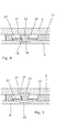
- Fig. 1 shows an embodiment of a downhole flow control device 1 according to the present invention in a cross-sectional view.
- the downhole flow control device 1 is adapted to control a flow of a fluid from a borehole 2 into a well tubular structure 10 and/or from the well tubular structure 10 into the borehole 2.
- the downhole flow control device 1 comprises a base tubular 3 having an axial axis 4 and being adapted to be mounted as part of the well tubular structure 10, the base tubular 3 having a first opening 5.
- the first opening 5 is arranged opposite the borehole 2.
- the downhole flow control device 1 furthermore comprises a first sleeve 6 which is arranged within the base tubular 3.
- the first sleeve 6 has a first sleeve part 7 and a second sleeve part 8 with a second opening 9.
- the first sleeve 6 is adapted to slide along the axial axis 4 for at least partly aligning the first opening 5 with the second opening 9, so that fluid communication may be provided between the borehole 2 and an inside 11 of the well tubular structure 10.
- a second sleeve 12 is arranged at least partly between the second sleeve part 8 and the base tubular 3, and an engagement element 13 is arranged for engaging an indentation 14 of the second sleeve part 8 in a first position which is the position shown in Fig. 1 .
- the engagement element 13 is furthermore adapted to disengage the indentation 14 of the second sleeve part 8 in a second position when the first and second sleeves 6, 12 have been slid along the axis 4 in relation to the base tubular.
- the second position is shown in Figs. 2 and 3 .
- the second sleeve 12 When the engagement element 13 is engaged in the indentation 14 of the second sleeve part 8, the second sleeve 12 will slide along the axial axis 4 together with the first sleeve 6, until the engagement element 13 disengages the indentation 14, causing the first sleeve 6 to be capable of sliding further along the axial axis 4 without the second sleeve 12 following along.
- the first and second sleeve abut each other, preventing scale or debris from precipitating as there is no opening therebetween to precipitate in.
- the disadvantages with scales and other debris settling in the openings and thereby minimising or even closing off the flow possibilities through the openings when these are aligned are eliminated, as the opening is not created until the first sleeve is moved away from the second sleeve.
- the downhole flow control device 1 also comprises a first sealing element 22 and a second sealing element 23.
- the first sealing element 22 is arranged in a first circumferential groove 24 in the inner face of the base tubular 3 on a first side of the first opening 5.
- the second sealing element 23 is arranged in a second circumferential groove 25 in the base tubular 3 on a second side of the first opening 5, where the second side is opposite the first side.
- the sealing elements 22, 23 are chevron seals.
- the first sealing element 22 is arranged between the first sleeve part 7 and the base tubular 3.
- the second sealing element 23 is arranged between the first sleeve part 7 and the base tubular 3 in the first position, as shown in Fig. 1 , and between the second sleeve 12 and the base tubular 3 in the second position as shown in Fig. 3 . Due to the fact that the first sleeve and the second sleeve abut each other when passing the first and the second sealing elements, risk of the sealing elements being damaged is minimised and it is hence obtained that their sealing properties are maintained, since the opening is not created until the second sleeve has passed the second sealing element.
- the embodiment of Fig.1 shows that the first sleeve part 7 and the second sleeve part 8 are two separate elements.
- the first sleeve part 7 has a first thickness (t 1,1 and a second thickness (t 1,2 ), where the second thickness is larger than the first thickness. Between the first thickness and the second thickness a first wall 15 is arranged. The first thickness is positioned closest to the second sleeve 12.
- the second sleeve part 8 has a first thickness (t 2,1 ) and a second thickness (t 2,2 ), where the first thickness is larger than the second thickness.
- the second opening 9 is positioned in the part of the second sleeve part 8 having the first thickness (t 2,1 ).
- a second wall 16 is arranged between the first thickness (t 2,1 ) and the second thickness (t 2,2 ) between the first thickness (t 2,1 ) and the second thickness (t 2,2 ) a second wall 16 is arranged.
- the first wall 15 and the second wall 16 are positioned opposite each other, with a distance between them defining a cavity 17 as shown in Fig. 1 .
- the second sleeve part 8 is, in the shown embodiment, capable of sliding along the axial axis 4 independently of the first sleeve part 7 until the second wall 16 abuts the first wall. This will be described further below in connection with Figs. 2 and 3 .
- first sleeve part 7 has a first end 18 and a second end 19 and the second sleeve 12 has a first end 20 and a second end 21, the first end 18 of the first sleeve part 7 abutting the second end 21 of the second sleeve 12 in the first position as shown in Fig. 1 .
- the second sleeve 12 may assist in sliding the first sleeve part 7 when the second sleeve part 8 is connected to the second sleeve 12 via the engagement element 13 and the second sleeve part 8 is moved along the axial axis 4.
- the first sleeve part 7 is a third sleeve 7 which abuts the second sleeve part 8, the first sleeve part 7 and the second sleeve part 8 yet still being slidable in relation to each other.
- the third sleeve 7 is arranged between the second sleeve part 8 and the base tubular 3.
- the second sleeve 12 of Fig. 1 has a through-going bore 26 in which the engagement element 13 is arranged.
- the engagement element 13 has a length which is larger than a thickness of the second sleeve 12.
- the through-going bore 26 is considerably larger than the width of the engagement element 13, so that a spring 27 may be arranged in connection with the engagement element 13.
- the spring 27 exerts a force on the engagement element 13 towards the base tubular 3, whereby the engagement element 13 is spring-loaded when engaging the indentation 14 in the second sleeve part 8 and will disengage the indentation 14 as soon as it is possible for the engagement element 13 to move in a radial direction away from the axial axis 4.
- the spring 27 is a leaf spring; however, other springs may be used such as for instance a helical spring arranged around the engagement element 13.
- the base tubular 3 has a recess 28 arranged opposite the second sleeve 12.
- the recess 28 is adapted to receive the engagement element 13 at the second position as shown in Figs. 2 and 3 .
- the second sleeve part 8 has an inner face 29 and at least one groove 30 in the inner face 29 for engagement with a key tool of a downhole tool (not shown).
- the second sleeve part 8 has a first end 31 and a second end 32, and a groove 30 is arranged in each end.
- an inside groove 33 is arranged between the second sleeve 12 and the first end 31, causing the second sleeve part 8 to be capable of moving in relation to the second sleeve 12 when the engagement element 13 has disengaged the indentation 14 in the second sleeve part 8.
- a single engagement element 13 is shown in the cross-sectional view of the downhole flow control device 1 shown in Fig. 1 . However, a plurality of engagement elements 13 may be arranged in the downhole flow control device.
- the first, second and third sleeves and the first and second sleeve parts may be made of metal.
- the first sleeve 6 of the downhole flow control device 1 of Fig. 1 is shown in an intermediate position being the second position of the second sleeve.
- the first sleeve 6 of the downhole flow control device 1 is shown in a third position and open position of the downhole flow control device 1 where the first and second openings are aligned.
- the second end 21 of the second sleeve 12 is still in this intermediate position abutting the first end 18 of the first sleeve part 7, whereby the second sleeve has pushed the first sleeve part 7 to this position.
- the second end 21 of the second sleeve 12 is arranged substantially at the first opening 5.
- the second sealing element 23 is arranged opposite the second sleeve 12.
- the first opening 5 is not aligned with the second opening 9 of the second sleeve part 8, whereby no fluid communication between the borehole 2 and the well tubular structure 10 is provided.
- Fig. 3 the downhole flow control device 1 is shown in the third position, wherein the first opening 5 is aligned with the second opening 9, so that fluid communication between the borehole 2 and the well tubular structure 10 is provided.
- the second sleeve part 8 has been disengaged from the second sleeve 12 and has been moved further to the right.
- the engagement element 13 has engaged the recess 28, whereby the second sleeve 12 is prevented from moving further to the right.
- the wall 16 of the second sleeve part will, after a little distance, abut the wall 15 of the first sleeve part 7, whereby the second sleeve part 8 will push the first sleeve part 7.
- the first sleeve part 7 will start moving away from the second sleeve 12, and thereby a distance between the second sleeve 12 and the first sleeve part 7 will be provided.
- the second opening 9 will also be moved towards the position of the first opening 5 and these two openings will then be aligned providing fluid communication between the borehole 2 and the well tubular structure 10.
- first end 31 of the second sleeve part 8 has been moved towards the second sleeve 12 by minimising the inside groove 33.
- first end 31 abuts the end of the second sleeve 12 facing the first end 31 of the second sleeve part 8.
- the first opening 5 and the second opening 9 have substantially the same width along the axial axis 4.
- the second opening 9 has a larger width than the first opening 5 so that if scale or debris precipitate, the second opening is just minimised but not minimised to be smaller than the first opening 5.
- the second sleeve part 8 may comprise a plurality of second openings, and the base tubular 3 may also comprise a plurality of first openings.
- FIG. 4 an enlarged partial view of the engagement element 13 is shown engaged in the indentation 14 of the second sleeve part 8.
- the second sleeve 12 is connected with the second sleeve part 8 and thereby follows the second sleeve part 8 when the second sleeve part 8 is being moved.
- the engagement element 13 comprises a first element part 35 and a second element part 36.
- the first element part 35 has a larger width than the second element part 36 which defines a protrusion 37 between the two element parts 35, 36.
- This protrusion is adapted for receiving the spring 27 so that the spring 27 exerts a force against the protrusion 37 in order to force the engagement element 13 in a radial outwards direction being the upwards direction in Fig. 4 and away from the indentation 14.
- the engagement element 13 is prevented from disengaging the indentation due to the wall of the base tubular 3.
- the second sleeve part 8 has been moved to the second position as shown in Fig. 2 , where the engagement element 13 is positioned opposite the recess 28 in the base tubular 3.
- the spring 27 forces the engagement element 13 radially outwards into the recess 28 and thereby the engagement element 13 disengages the indentation 14. Consequently, the connection between the second sleeve 12 and the second sleeve part 8 is disengaged, whereby the second sleeve part 8 may be moved independently of the second sleeve 12, and the second sleeve 12 is then securely positioned in relation to the base tubular 3 since the engagement element 13 has engaged the recess 28.
- the base tubular may be mounted from at least two tubular sections.
- the first sleeve part 7 and the second sleeve part 8 is produced as one sleeve 6.
- the procedure of aligning the first opening 5 in the base tubular 3 with the second opening 9 in the second sleeve part 8 for providing fluid communication between the borehole 2 and the well tubular structure 10, is performed in substantially the same manner as described above in connection with the embodiment shown in Figs. 1-3 , except from the first sleeve part 7 and the second sleeve part 8 not being able to move independently of each other.
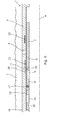
- the downhole flow control device 1 may be arranged within an inside groove or cavity of the well tubular structure 10 as shown in Fig. 6 .
- the base tubular may have an elongated projection extending along the axial axis for pressing the engagement element in engagement with the second sleeve and the second sleeve part until reaching the second position, and then the elongated projection ends and the engagement element disengage the second sleeve part.
- the engagement element may be a spring-loaded circlip.
- the flow control device 1 may be a frac port or an inflow control device or a valve.
- Fig. 7 shows a downhole system 100 for producing hydrocarbon-containing fluid from a reservoir 40 downhole.
- the downhole well system 100 comprises a well tubular structure 10 having an inside 41 for conducting the well fluid to surface.
- the downhole system 100 comprises a first annular barrier 50 and a second annular barrier 51 to isolate a production zone 101 when the annular barriers are expanded.
- Each annular barrier comprises a tubular part 52 adapted to be mounted as part of the well tubular structure 10 by means of a thread, an expandable metal sleeve 53 surrounding the tubular part and an annular space 54 between the inner sleeve face of the expandable sleeve and the tubular part.
- the expandable metal sleeve 53 has an inner sleeve face 55 facing the tubular part and an outer sleeve face 56 facing a wall 57 of a borehole 2, each end of the expandable sleeve being connected with the tubular part, which provides the isolating barrier when the expandable sleeve is expanded.
- the downhole system 100 further comprises a downhole flow control device 1 mounted as part of the well tubular structure 10 and arranged between the first and the second annular barriers opposite the production zone 101 for controlling a flow of a fluid from the borehole 2 into the well tubular structure 10 and/or from the well tubular structure 10 into the borehole 2.
- a downhole flow control device 1 mounted as part of the well tubular structure 10 and arranged between the first and the second annular barriers opposite the production zone 101 for controlling a flow of a fluid from the borehole 2 into the well tubular structure 10 and/or from the well tubular structure 10 into the borehole 2.
- fluid or well fluid any kind of fluid that may be present in oil or gas wells downhole, such as natural gas, oil, oil mud, crude oil, water, etc.
- gas is meant any kind of gas composition present in a well, completion, or open hole
- oil is meant any kind of oil composition, such as crude oil, an oil-containing fluid, etc.
- Gas, oil, and water fluids may thus all comprise other elements or substances than gas, oil, and/or water, respectively.
- a downhole tractor can be used to push the tool all the way into position in the well.
- the downhole tractor may have projectable arms having wheels, wherein the wheels contact the inner surface of the casing for propelling the tractor and the tool forward in the casing.
- a downhole tractor is any kind of driving tool capable of pushing or pulling tools in a well downhole, such as a Well Tractor®.
Landscapes
- Geology (AREA)
- Life Sciences & Earth Sciences (AREA)
- Engineering & Computer Science (AREA)
- Mining & Mineral Resources (AREA)
- Environmental & Geological Engineering (AREA)
- Fluid Mechanics (AREA)
- Physics & Mathematics (AREA)
- General Life Sciences & Earth Sciences (AREA)
- Geochemistry & Mineralogy (AREA)
- Quick-Acting Or Multi-Walled Pipe Joints (AREA)
- Flow Control (AREA)
- Pipe Accessories (AREA)
- Lift Valve (AREA)
Priority Applications (11)
| Application Number | Priority Date | Filing Date | Title |
|---|---|---|---|
| EP14174961.4A EP2963232A1 (de) | 2014-06-30 | 2014-06-30 | Bohrlochflusssteuerungsvorrichtung |
| MYPI2016002233A MY186095A (en) | 2014-06-30 | 2015-06-29 | A downhole flow control device |
| CN201580031846.4A CN106460485B (zh) | 2014-06-30 | 2015-06-29 | 井下流动控制装置 |
| EP15731378.4A EP3161246B1 (de) | 2014-06-30 | 2015-06-29 | Bohrlochflusssteuerungsvorrichtung |
| AU2015282638A AU2015282638B2 (en) | 2014-06-30 | 2015-06-29 | A downhole flow control device |
| RU2017100123A RU2698358C2 (ru) | 2014-06-30 | 2015-06-29 | Внутрискважинное устройство регулирования потока |
| CA2952748A CA2952748A1 (en) | 2014-06-30 | 2015-06-29 | A downhole flow control device |
| PCT/EP2015/064704 WO2016001141A1 (en) | 2014-06-30 | 2015-06-29 | A downhole flow control device |
| BR112016029422A BR112016029422A2 (pt) | 2014-06-30 | 2015-06-29 | dispositivo de controle de fluxo de fundo de poço |
| US15/322,563 US10385655B2 (en) | 2014-06-30 | 2015-06-29 | Downhole flow control device |
| MX2016017134A MX2016017134A (es) | 2014-06-30 | 2015-06-29 | Dispositivo de control de flujo de fondo de perforacion. |
Applications Claiming Priority (1)
| Application Number | Priority Date | Filing Date | Title |
|---|---|---|---|
| EP14174961.4A EP2963232A1 (de) | 2014-06-30 | 2014-06-30 | Bohrlochflusssteuerungsvorrichtung |
Publications (1)
| Publication Number | Publication Date |
|---|---|
| EP2963232A1 true EP2963232A1 (de) | 2016-01-06 |
Family
ID=51167627
Family Applications (2)
| Application Number | Title | Priority Date | Filing Date |
|---|---|---|---|
| EP14174961.4A Withdrawn EP2963232A1 (de) | 2014-06-30 | 2014-06-30 | Bohrlochflusssteuerungsvorrichtung |
| EP15731378.4A Not-in-force EP3161246B1 (de) | 2014-06-30 | 2015-06-29 | Bohrlochflusssteuerungsvorrichtung |
Family Applications After (1)
| Application Number | Title | Priority Date | Filing Date |
|---|---|---|---|
| EP15731378.4A Not-in-force EP3161246B1 (de) | 2014-06-30 | 2015-06-29 | Bohrlochflusssteuerungsvorrichtung |
Country Status (10)
| Country | Link |
|---|---|
| US (1) | US10385655B2 (de) |
| EP (2) | EP2963232A1 (de) |
| CN (1) | CN106460485B (de) |
| AU (1) | AU2015282638B2 (de) |
| BR (1) | BR112016029422A2 (de) |
| CA (1) | CA2952748A1 (de) |
| MX (1) | MX2016017134A (de) |
| MY (1) | MY186095A (de) |
| RU (1) | RU2698358C2 (de) |
| WO (1) | WO2016001141A1 (de) |
Cited By (1)
| Publication number | Priority date | Publication date | Assignee | Title |
|---|---|---|---|---|
| WO2023122826A1 (en) * | 2021-12-30 | 2023-07-06 | Ncs Multistage Inc. | Valve assemblies for high-temperature wells |
Families Citing this family (2)
| Publication number | Priority date | Publication date | Assignee | Title |
|---|---|---|---|---|
| CN107313738B (zh) * | 2017-09-06 | 2019-12-20 | 刘书豪 | 流体分隔装置、井道结构及石油或天然气的生产方法 |
| US12123277B2 (en) | 2021-06-02 | 2024-10-22 | Halliburton Energy Services, Inc. | Sealing assembly for wellbore operations |
Citations (6)
| Publication number | Priority date | Publication date | Assignee | Title |
|---|---|---|---|---|
| US3051243A (en) * | 1958-12-12 | 1962-08-28 | George G Grimmer | Well tools |
| US3071193A (en) * | 1960-06-02 | 1963-01-01 | Camco Inc | Well tubing sliding sleeve valve |
| EP0224942A1 (de) * | 1985-10-04 | 1987-06-10 | Compagnie Des Services Dowell Schlumberger | Gerät zur abschnittweisen Zementation |
| US4949788A (en) * | 1989-11-08 | 1990-08-21 | Halliburton Company | Well completions using casing valves |
| US20020074128A1 (en) * | 2000-12-14 | 2002-06-20 | Allamon Jerry P. | Method and apparatus for surge reduction |
| US20070240883A1 (en) * | 2004-05-26 | 2007-10-18 | George Telfer | Downhole Tool |
Family Cites Families (13)
| Publication number | Priority date | Publication date | Assignee | Title |
|---|---|---|---|---|
| SU817212A1 (ru) | 1979-06-25 | 1981-03-30 | Всесоюзный Ордена Трудового Красно-Го Знамени Научно-Исследовательскийинститут Буровой Техники | Устройство дл поинтервальнойизОл ции зОНы пОглОщЕНи |
| SU1213175A1 (ru) | 1984-03-14 | 1986-02-23 | Всесоюзный Ордена Трудового Красного Знамени Научно-Исследовательский Институт Буровой Техники | Пакер гидравлический |
| SU1709070A1 (ru) | 1989-11-01 | 1992-01-30 | Всесоюзный Научно-Исследовательский Институт Буровой Техники | Устройство дл освоени и эксплуатации скважин |
| US6422317B1 (en) * | 2000-09-05 | 2002-07-23 | Halliburton Energy Services, Inc. | Flow control apparatus and method for use of the same |
| US6976542B2 (en) * | 2003-10-03 | 2005-12-20 | Baker Hughes Incorporated | Mud flow back valve |
| RU2305170C2 (ru) | 2004-01-13 | 2007-08-27 | Махир Зафар оглы Шарифов | Пакерная разъединяющая установка шарифова для эксплуатации пластов скважины (варианты) |
| US7681645B2 (en) * | 2007-03-01 | 2010-03-23 | Bj Services Company | System and method for stimulating multiple production zones in a wellbore |
| CN103459769B (zh) * | 2011-01-10 | 2016-04-13 | 斯塔特伊石油公司 | 适于生产管的阀布置 |
| US9200502B2 (en) * | 2011-06-22 | 2015-12-01 | Schlumberger Technology Corporation | Well-based fluid communication control assembly |
| EP2538018A1 (de) * | 2011-06-23 | 2012-12-26 | Welltec A/S | Ringförmige Absperrung mit äußerer Dichtung |
| GB201205985D0 (en) * | 2012-04-03 | 2012-05-16 | Petrowell Ltd | Frac packing tools |
| RU2507375C1 (ru) | 2012-08-02 | 2014-02-20 | Закрытое акционерное общество "Газтехнология" | Разбуриваемый пакер |
| CN203175485U (zh) * | 2013-01-22 | 2013-09-04 | 中国石油天然气股份有限公司 | 滑套控制工具及可超越操作的液控滑套 |
-
2014
- 2014-06-30 EP EP14174961.4A patent/EP2963232A1/de not_active Withdrawn
-
2015
- 2015-06-29 MY MYPI2016002233A patent/MY186095A/en unknown
- 2015-06-29 CN CN201580031846.4A patent/CN106460485B/zh not_active Expired - Fee Related
- 2015-06-29 WO PCT/EP2015/064704 patent/WO2016001141A1/en not_active Ceased
- 2015-06-29 US US15/322,563 patent/US10385655B2/en not_active Expired - Fee Related
- 2015-06-29 MX MX2016017134A patent/MX2016017134A/es unknown
- 2015-06-29 CA CA2952748A patent/CA2952748A1/en not_active Abandoned
- 2015-06-29 EP EP15731378.4A patent/EP3161246B1/de not_active Not-in-force
- 2015-06-29 BR BR112016029422A patent/BR112016029422A2/pt active Search and Examination
- 2015-06-29 RU RU2017100123A patent/RU2698358C2/ru active
- 2015-06-29 AU AU2015282638A patent/AU2015282638B2/en not_active Ceased
Patent Citations (6)
| Publication number | Priority date | Publication date | Assignee | Title |
|---|---|---|---|---|
| US3051243A (en) * | 1958-12-12 | 1962-08-28 | George G Grimmer | Well tools |
| US3071193A (en) * | 1960-06-02 | 1963-01-01 | Camco Inc | Well tubing sliding sleeve valve |
| EP0224942A1 (de) * | 1985-10-04 | 1987-06-10 | Compagnie Des Services Dowell Schlumberger | Gerät zur abschnittweisen Zementation |
| US4949788A (en) * | 1989-11-08 | 1990-08-21 | Halliburton Company | Well completions using casing valves |
| US20020074128A1 (en) * | 2000-12-14 | 2002-06-20 | Allamon Jerry P. | Method and apparatus for surge reduction |
| US20070240883A1 (en) * | 2004-05-26 | 2007-10-18 | George Telfer | Downhole Tool |
Cited By (3)
| Publication number | Priority date | Publication date | Assignee | Title |
|---|---|---|---|---|
| WO2023122826A1 (en) * | 2021-12-30 | 2023-07-06 | Ncs Multistage Inc. | Valve assemblies for high-temperature wells |
| US12473798B2 (en) | 2021-12-30 | 2025-11-18 | Ncs Multistage Inc. | Valve assemblies for high-temperature wells |
| EP4457424A4 (de) * | 2021-12-30 | 2025-11-26 | Ncs Multistage Inc | Ventilanordnungen für hochtemperaturbohrlöcher |
Also Published As
| Publication number | Publication date |
|---|---|
| WO2016001141A1 (en) | 2016-01-07 |
| RU2698358C2 (ru) | 2019-08-26 |
| AU2015282638A1 (en) | 2017-02-02 |
| EP3161246B1 (de) | 2020-10-07 |
| RU2017100123A (ru) | 2018-07-30 |
| BR112016029422A2 (pt) | 2017-08-22 |
| CA2952748A1 (en) | 2016-01-07 |
| MX2016017134A (es) | 2017-05-03 |
| CN106460485B (zh) | 2020-02-07 |
| US10385655B2 (en) | 2019-08-20 |
| AU2015282638B2 (en) | 2018-07-26 |
| RU2017100123A3 (de) | 2019-02-11 |
| US20170122066A1 (en) | 2017-05-04 |
| EP3161246A1 (de) | 2017-05-03 |
| CN106460485A (zh) | 2017-02-22 |
| MY186095A (en) | 2021-06-21 |
Similar Documents
| Publication | Publication Date | Title |
|---|---|---|
| US11268348B2 (en) | System for successively uncovering ports along a wellbore to permit injection of a fluid along said wellbore | |
| CA2927850C (en) | System for successively uncovering ports along a wellbore to permit injection of a fluid along said wellbore | |
| EP3218573B1 (de) | Ringförmige barriere mit schliessmechanismus | |
| US11193353B2 (en) | Sliding sleeve well tool with metal-to-metal seal | |
| US9850742B2 (en) | Reclosable sleeve assembly and methods for isolating hydrocarbon production | |
| EP3161246B1 (de) | Bohrlochflusssteuerungsvorrichtung | |
| AU2014229773B2 (en) | Downhole arrangement | |
| EP2971477B1 (de) | Expandierbarer kugelsitz für hydraulisch betätigte werkzeuge | |
| EP2652241B1 (de) | Bohrlochkomplettierung | |
| EP3274545B1 (de) | Eine bohrlochrohrstruktur | |
| US10214996B2 (en) | Method and apparatus to utilize a metal to metal seal | |
| US20260117620A1 (en) | Downhole fluid flow control device |
Legal Events
| Date | Code | Title | Description |
|---|---|---|---|
| PUAI | Public reference made under article 153(3) epc to a published international application that has entered the european phase |
Free format text: ORIGINAL CODE: 0009012 |
|
| AK | Designated contracting states |
Kind code of ref document: A1 Designated state(s): AL AT BE BG CH CY CZ DE DK EE ES FI FR GB GR HR HU IE IS IT LI LT LU LV MC MK MT NL NO PL PT RO RS SE SI SK SM TR |
|
| AX | Request for extension of the european patent |
Extension state: BA ME |
|
| STAA | Information on the status of an ep patent application or granted ep patent |
Free format text: STATUS: THE APPLICATION IS DEEMED TO BE WITHDRAWN |
|
| 18D | Application deemed to be withdrawn |
Effective date: 20160707 |