EP2963393A1 - Absolutcodierer - Google Patents
Absolutcodierer Download PDFInfo
- Publication number
- EP2963393A1 EP2963393A1 EP15001887.7A EP15001887A EP2963393A1 EP 2963393 A1 EP2963393 A1 EP 2963393A1 EP 15001887 A EP15001887 A EP 15001887A EP 2963393 A1 EP2963393 A1 EP 2963393A1
- Authority
- EP
- European Patent Office
- Prior art keywords
- marks
- codes
- scale
- encoder according
- detecting devices
- Prior art date
- Legal status (The legal status is an assumption and is not a legal conclusion. Google has not performed a legal analysis and makes no representation as to the accuracy of the status listed.)
- Granted
Links
Images






Classifications
-
- G—PHYSICS
- G01—MEASURING; TESTING
- G01D—MEASURING NOT SPECIALLY ADAPTED FOR A SPECIFIC VARIABLE; ARRANGEMENTS FOR MEASURING TWO OR MORE VARIABLES NOT COVERED IN A SINGLE OTHER SUBCLASS; TARIFF METERING APPARATUS; MEASURING OR TESTING NOT OTHERWISE PROVIDED FOR
- G01D5/00—Mechanical means for transferring the output of a sensing member; Means for converting the output of a sensing member to another variable where the form or nature of the sensing member does not constrain the means for converting; Transducers not specially adapted for a specific variable
- G01D5/26—Mechanical means for transferring the output of a sensing member; Means for converting the output of a sensing member to another variable where the form or nature of the sensing member does not constrain the means for converting; Transducers not specially adapted for a specific variable characterised by optical transfer means, i.e. using infrared, visible, or ultraviolet light
- G01D5/32—Mechanical means for transferring the output of a sensing member; Means for converting the output of a sensing member to another variable where the form or nature of the sensing member does not constrain the means for converting; Transducers not specially adapted for a specific variable characterised by optical transfer means, i.e. using infrared, visible, or ultraviolet light with attenuation or whole or partial obturation of beams of light
- G01D5/34—Mechanical means for transferring the output of a sensing member; Means for converting the output of a sensing member to another variable where the form or nature of the sensing member does not constrain the means for converting; Transducers not specially adapted for a specific variable characterised by optical transfer means, i.e. using infrared, visible, or ultraviolet light with attenuation or whole or partial obturation of beams of light the beams of light being detected by photocells
- G01D5/347—Mechanical means for transferring the output of a sensing member; Means for converting the output of a sensing member to another variable where the form or nature of the sensing member does not constrain the means for converting; Transducers not specially adapted for a specific variable characterised by optical transfer means, i.e. using infrared, visible, or ultraviolet light with attenuation or whole or partial obturation of beams of light the beams of light being detected by photocells using displacement encoding scales
- G01D5/34776—Absolute encoders with analogue or digital scales
- G01D5/34792—Absolute encoders with analogue or digital scales with only digital scales or both digital and incremental scales
-
- G—PHYSICS
- G01—MEASURING; TESTING
- G01D—MEASURING NOT SPECIALLY ADAPTED FOR A SPECIFIC VARIABLE; ARRANGEMENTS FOR MEASURING TWO OR MORE VARIABLES NOT COVERED IN A SINGLE OTHER SUBCLASS; TARIFF METERING APPARATUS; MEASURING OR TESTING NOT OTHERWISE PROVIDED FOR
- G01D5/00—Mechanical means for transferring the output of a sensing member; Means for converting the output of a sensing member to another variable where the form or nature of the sensing member does not constrain the means for converting; Transducers not specially adapted for a specific variable
- G01D5/12—Mechanical means for transferring the output of a sensing member; Means for converting the output of a sensing member to another variable where the form or nature of the sensing member does not constrain the means for converting; Transducers not specially adapted for a specific variable using electric or magnetic means
- G01D5/244—Mechanical means for transferring the output of a sensing member; Means for converting the output of a sensing member to another variable where the form or nature of the sensing member does not constrain the means for converting; Transducers not specially adapted for a specific variable using electric or magnetic means influencing characteristics of pulses or pulse trains; generating pulses or pulse trains
- G01D5/24457—Failure detection
- G01D5/24461—Failure detection by redundancy or plausibility
-
- G—PHYSICS
- G01—MEASURING; TESTING
- G01D—MEASURING NOT SPECIALLY ADAPTED FOR A SPECIFIC VARIABLE; ARRANGEMENTS FOR MEASURING TWO OR MORE VARIABLES NOT COVERED IN A SINGLE OTHER SUBCLASS; TARIFF METERING APPARATUS; MEASURING OR TESTING NOT OTHERWISE PROVIDED FOR
- G01D5/00—Mechanical means for transferring the output of a sensing member; Means for converting the output of a sensing member to another variable where the form or nature of the sensing member does not constrain the means for converting; Transducers not specially adapted for a specific variable
- G01D5/12—Mechanical means for transferring the output of a sensing member; Means for converting the output of a sensing member to another variable where the form or nature of the sensing member does not constrain the means for converting; Transducers not specially adapted for a specific variable using electric or magnetic means
- G01D5/244—Mechanical means for transferring the output of a sensing member; Means for converting the output of a sensing member to another variable where the form or nature of the sensing member does not constrain the means for converting; Transducers not specially adapted for a specific variable using electric or magnetic means influencing characteristics of pulses or pulse trains; generating pulses or pulse trains
- G01D5/245—Mechanical means for transferring the output of a sensing member; Means for converting the output of a sensing member to another variable where the form or nature of the sensing member does not constrain the means for converting; Transducers not specially adapted for a specific variable using electric or magnetic means influencing characteristics of pulses or pulse trains; generating pulses or pulse trains using a variable number of pulses in a train
- G01D5/2454—Encoders incorporating incremental and absolute signals
- G01D5/2455—Encoders incorporating incremental and absolute signals with incremental and absolute tracks on the same encoder
-
- G—PHYSICS
- G01—MEASURING; TESTING
- G01D—MEASURING NOT SPECIALLY ADAPTED FOR A SPECIFIC VARIABLE; ARRANGEMENTS FOR MEASURING TWO OR MORE VARIABLES NOT COVERED IN A SINGLE OTHER SUBCLASS; TARIFF METERING APPARATUS; MEASURING OR TESTING NOT OTHERWISE PROVIDED FOR
- G01D5/00—Mechanical means for transferring the output of a sensing member; Means for converting the output of a sensing member to another variable where the form or nature of the sensing member does not constrain the means for converting; Transducers not specially adapted for a specific variable
- G01D5/26—Mechanical means for transferring the output of a sensing member; Means for converting the output of a sensing member to another variable where the form or nature of the sensing member does not constrain the means for converting; Transducers not specially adapted for a specific variable characterised by optical transfer means, i.e. using infrared, visible, or ultraviolet light
- G01D5/32—Mechanical means for transferring the output of a sensing member; Means for converting the output of a sensing member to another variable where the form or nature of the sensing member does not constrain the means for converting; Transducers not specially adapted for a specific variable characterised by optical transfer means, i.e. using infrared, visible, or ultraviolet light with attenuation or whole or partial obturation of beams of light
- G01D5/34—Mechanical means for transferring the output of a sensing member; Means for converting the output of a sensing member to another variable where the form or nature of the sensing member does not constrain the means for converting; Transducers not specially adapted for a specific variable characterised by optical transfer means, i.e. using infrared, visible, or ultraviolet light with attenuation or whole or partial obturation of beams of light the beams of light being detected by photocells
- G01D5/347—Mechanical means for transferring the output of a sensing member; Means for converting the output of a sensing member to another variable where the form or nature of the sensing member does not constrain the means for converting; Transducers not specially adapted for a specific variable characterised by optical transfer means, i.e. using infrared, visible, or ultraviolet light with attenuation or whole or partial obturation of beams of light the beams of light being detected by photocells using displacement encoding scales
- G01D5/3473—Circular or rotary encoders
-
- G—PHYSICS
- G01—MEASURING; TESTING
- G01D—MEASURING NOT SPECIALLY ADAPTED FOR A SPECIFIC VARIABLE; ARRANGEMENTS FOR MEASURING TWO OR MORE VARIABLES NOT COVERED IN A SINGLE OTHER SUBCLASS; TARIFF METERING APPARATUS; MEASURING OR TESTING NOT OTHERWISE PROVIDED FOR
- G01D5/00—Mechanical means for transferring the output of a sensing member; Means for converting the output of a sensing member to another variable where the form or nature of the sensing member does not constrain the means for converting; Transducers not specially adapted for a specific variable
- G01D5/26—Mechanical means for transferring the output of a sensing member; Means for converting the output of a sensing member to another variable where the form or nature of the sensing member does not constrain the means for converting; Transducers not specially adapted for a specific variable characterised by optical transfer means, i.e. using infrared, visible, or ultraviolet light
- G01D5/32—Mechanical means for transferring the output of a sensing member; Means for converting the output of a sensing member to another variable where the form or nature of the sensing member does not constrain the means for converting; Transducers not specially adapted for a specific variable characterised by optical transfer means, i.e. using infrared, visible, or ultraviolet light with attenuation or whole or partial obturation of beams of light
- G01D5/34—Mechanical means for transferring the output of a sensing member; Means for converting the output of a sensing member to another variable where the form or nature of the sensing member does not constrain the means for converting; Transducers not specially adapted for a specific variable characterised by optical transfer means, i.e. using infrared, visible, or ultraviolet light with attenuation or whole or partial obturation of beams of light the beams of light being detected by photocells
- G01D5/347—Mechanical means for transferring the output of a sensing member; Means for converting the output of a sensing member to another variable where the form or nature of the sensing member does not constrain the means for converting; Transducers not specially adapted for a specific variable characterised by optical transfer means, i.e. using infrared, visible, or ultraviolet light with attenuation or whole or partial obturation of beams of light the beams of light being detected by photocells using displacement encoding scales
- G01D5/34776—Absolute encoders with analogue or digital scales
- G01D5/34784—Absolute encoders with analogue or digital scales with only analogue scales or both analogue and incremental scales
Definitions
- the present invention relates to an absolute encoder.
- An absolute encoder is used for the purpose of measuring the absolute value (absolute coordinate) of a position or an angle.
- the absolute encoder can output absolute position information by reading a binary pattern of gray codes, M-sequence codes, or the like using a photoelectric conversion element array or an image sensor (imaging element or imaging device).
- Some absolute encoders use a plurality of grating arrays (mark arrays), and some use a single grating array.
- a gray code method is known. In the gray code method, pieces of information of a plurality of tracks to locate different codes are simultaneously read. Since the plurality of tracks are simultaneously read, the gray code method has a problem that the mount sensitivity of an encoder head and a scale is high, and it is difficult to implement a high resolution.
- Japanese Patent Laid-Open No. 2012-37392 discloses an absolute encoder that raises the resolution using a single grating array.
- the absolute encoder disclosed in Japanese Patent Laid-Open No. 2012-37392 embeds codes corresponding to absolute codes in the single grating array with grayscales, and uses a signal having a grayscale as the peak value of each grating (mark).
- the absolute encoder disclosed in Japanese Patent Laid-Open No. 2012-37392 integrates absolute position information obtained based on the grayscales and the phase information of a periodic signal obtained from the signal, and outputs high-resolution absolute position information.
- Japanese Patent Laid-Open No. 2012-127818 discloses an absolute rotary encoder having a high resolution and high accuracy implemented by applying the method to an absolute encoder.
- the present invention provides, for example, an absolute encoder advantageous in terms of operation load thereto.
- the present invention provides an absolute encoder as specified in claims 1 to 14.
- Figs. 1A and 1B are views for explaining the arrangement of an absolute encoder according to the first embodiment.
- the absolute encoder according to the embodiment is formed as an absolute rotary encoder that includes a scale in which a plurality of marks are arrayed at a gap and a pitch on a disc (rotating member) that rotates about an axis serving as a rotation center, and calculates the absolute rotation angle of the scale.
- detecting devices (heads) 3 are located to have point symmetry (two-fold rotational symmetry) and face each other at 180°, and a binary code will be exemplified as an absolute code. As shown in Fig.
- the absolute rotary encoder includes a disc-shaped scale 1, two heads 3a and 3b, and a processor P that obtains the coordinate of the scale 1.
- the scale 1 is configured to be rotatable about an axis 2 serving as a rotation center.
- a plurality of marks including at least two types of marks are radially arrayed at a predetermined period about the axis 2 along the circumferential direction.
- Fig. 1B is a sectional view of Fig. 1A .
- Each of the heads 3 includes a light source 4, and a photoelectric conversion element array (detector) 5 including a plurality of photoelectric conversion elements.
- the two heads 3a and 3b are placed at point-symmetrical positions shifted by 180° from each other.
- Fig. 2 is a view showing the relationship between the scale 1, the light source 4, and the photoelectric conversion element array 5.
- diverging light emitted by the point light source 4 which may be an LED enters the scale 1 that is placed to be relatively movable, and the light transmitted through the scale 1 is detected by the photoelectric conversion element array 5.
- the scale 1 has a structure in which non-transmissive marks 1b are located as reference marks, and transmissive marks 1a and semi-transmissive marks 1c serving as code marks and having the same shape and transmittances different from each other are arrayed between the non-transmissive marks 1b, thereby embedding absolute codes.
- the transmittances of the transmissive marks 1a, the non-transmissive marks 1b, and the semi-transmissive marks 1c, which are different from each other, can be set to, for example, 60%, 5%, and 30%, respectively.
- the transmissive marks 1a and the non-transmissive marks 1b can be implemented by depositing a metal or the like onto glass that makes the scale 1 and processing it into a slit shape.
- the semi-transmissive marks 1c can be implemented either by selectively depositing a dielectric film or the like onto the slit portions or by selectively changing the area of the slit.
- M-sequence codes formed by setting the transmissive marks 1a to 1 and the semi-transmissive marks 1c to 0 or other cyclic codes generated by a primitive polynomial are usable.
- a light beam transmitted through the scale 1 has a sinusoidal periodicity like a periodicity obtained by an incremental encoder, and the amplitude that reflects the information of the absolute codes is modulated to form a light amount distribution having a change in the grayscale.
- Fig. 2 shows a light amount distribution 6 of light transmitted through a mark group at part of the scale 1 detected by the photoelectric conversion element array 5.
- the photoelectric conversion element array 5 is formed from a CMOS or CCD sensor.
- the photoelectric conversion element array 5 is configured such that the phases of signals output from the photoelectric conversion elements are shifted at equal intervals by deciding the design value of the pitch of the photoelectric conversion elements so as to divide a design value P of one light/shade period of the light amount distribution decided by the arrangement of the optical system into N parts.
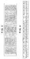
- Fig. 3 shows an example of a code sequence including 1,000 codes.
- An absolute rotary encoder of 1,000 pulses can be formed using this code sequence.
- the design value P of one light/shade period of the light amount distribution is set to, for example, 160 um.
- the code sequence shown in Fig. 3 is created by inverting the codes at the positions of 180° rotational symmetry with respect to the rotation center 2 of the scale 1 from each other.
- the code sequence of the first to 500th codes and that of the 501st to 1,000th codes are inverted code sequences having characteristics complementary to each other and different from each other. That is, in the first and 501st codes, second and 502nd codes,..., 499th and 999th codes, and 500th and 1,000th codes, if one of the codes is 1, the other is 0, and if one of the codes is 0, the other is 1. In other words, the sum of one code and the other code is always 1.
- Fig. 3 are numbered No. 1, No. 2, No. 3,... from the first code.
- Fig. 4 shows an example in which the codes of marks No. 501 to No. 516 are inverted with respect to the codes of marks No. 1 to No. 16.
- the code sequence shown in Fig. 3 forms 16-bit pseudo-random number sequences as well. That is, in this code sequence, all code sequences of 16-bit consecutive codes do not have the same code sequence.
- Figs. 5A and 5B are views showing the relationship between the scale 1 and the photoelectric conversion element array 5 of the absolute rotary encoder according to the first embodiment.
- Fig. 5A is a view showing a state in which codes No. 1 to No. 16 of the code sequence shown in Fig. 3 are read by a photoelectric conversion element array 5a.
- Fig. 5B is a view showing a state in which codes No. 501 to No. 516 of the code sequence shown in Fig. 3 are read by a photoelectric conversion element array 5b.
- the white, black, and hatched portions in Figs. 5A and 5B represent the transmissive marks 1a, the non-transmissive marks 1b, and the semi-transmissive marks 1c, respectively.
- the photoelectric conversion element array 5a is divided into light-receiving elements which are referred to as Ch1, Ch2,..., Ch192 sequentially from the left side.
- the photoelectric conversion element array 5b is divided into light-receiving elements which are referred to as Ch1, Ch2,..., Ch192.
- Fig. 5C shows an output signal reflecting the light amount distribution 6 output from the photoelectric conversion element array 5a.
- Fig. 5D shows an output signal reflecting the light amount distribution 6 output from the photoelectric conversion element array 5b. Ch numbers of the photoelectric conversion element array are plotted along the abscissa, and the values of the output signal reflecting the light amount distribution are plotted along the ordinate.
- the code sequence shown in Fig. 3 includes cyclic codes in which the codes at the positions of 180° rotational symmetry on the scale 1 are inverted.
- Figs. 5C and 5D periodic signals in which the change in the grayscale reflecting the information of the absolute codes is inverted are output. Waveform data shown in Fig.
- waveform data a will be referred to as waveform data a
- waveform data shown in Fig. 5D will be referred to as waveform data b
- Fig. 5E shows waveform data obtained by adding the waveform data a and the waveform data b for each Ch.
- Fig. 5F shows waveform data obtained by subtracting the waveform data b from the waveform data a for each Ch.
- the waveform data a and the waveform data b are periodic signals in which the change in the grayscale is inverted. For this reason, when they are added, a periodic signal having a predetermined amplitude is obtained, as shown in Fig. 5E .
- the processor P also performs phase calculation for the signal shown in Fig. 5E and code determination for the signal shown in Fig. 5F , thereby outputting absolute position information.
- Fig. 6 shows the procedure of signal processing performed by the processor P of the absolute rotary encoder according to the first embodiment.
- the processor P first acquires the waveform data a and b from the opposing photoelectric conversion element arrays 5a and 5b, respectively.
- the processor P performs addition and subtraction of the two acquired waveform data a and b, thereby generating a periodic signal (a + b) having a predetermined amplitude and a code determination signal (a - b) having a large grayscale difference.
- the processor P performs the phase calculation, for example, in the following way.
- the processor P multiplies, for example, each of four reference signals by the output value and performs an inverse tangent operation of the total sum of the signals, thereby deciding a phase at the same accuracy as an incremental encoder.
- the four reference signals for example, four signals having a phase difference of ⁇ /4 and a predetermined amplitude at the same period as the design value of the light/shade period of the output signal can be used.
- the method of calculating the phase from the signal obtained by addition has been described above. However, a phase may be calculated from each of the waveform data a and b, and the obtained phases may be averaged to calculate the phase.
- the processor P performs code determination, for example, in the following way.
- the processor P compares the magnitudes of output values between each CH and adjacent CHs for one of the waveform data a , waveform data b, and the data (a - b) obtained by subtraction, and decides the CH (peak CH) as the local maximum of the periodic signal.
- a periodic signal corresponding to 16 periods is acquired.
- 16 peak CHs are decided.
- the data of the peak CHs to be used for data code determination are extracted from the data (a - b).
- the processor P performs threshold determination for the code determination data (the data of the peak CHs) and quantizes the amplitude of the periodic signal, thereby calculating the absolute codes.
- FIG. 6 shows a graph of code determination data extracted from the data (a - b).
- the threshold is set as indicated by the dotted line, thereby determining each code depending on whether the code determination data is positive or negative. If the code determination data is positive, the code is determined as 1. If the code determination data is negative, the code is determined as 0. Then, 1110111111101111 is obtained as the absolute codes.
- the absolute codes obtained by the code determination data match the absolute codes of the photoelectric conversion element array 5a.
- the photoelectric conversion element array 5a serves as the reference position as the encoder.
- the threshold determination method is changed, or the order of subtraction is changed.
- the method of determining the codes from the signal obtained by subtraction has been described above.
- the code determination may be done by setting a threshold for the waveform data a or the waveform data b.
- the processor P acquires the data (first position data) of the integer part of the absolute position from the absolute codes using a lookup table (not shown) created in advance.
- the processor P composites the data of the integer part of the absolute position and the data (second position data) of the decimal part calculated from the phase and having a minimum unit (resolution) smaller than the first position data so as to calculate the absolute position.
- cyclic codes in which the codes at the positions of 180° rotational symmetry are inverted are added to the scale 1, and the photoelectric conversion element arrays 5a and 5b are provided at the opposing positions on the scale 1. In the first embodiment, this can implement an accurate absolute rotary encoder having an arrangement of light calculation load.
- the transmittances of the transmissive marks 1a, the non-transmissive marks 1b, and the semi-transmissive marks 1c are set to 60%, 5%, and 30%, respectively.
- an arrangement that sets the same transmittance value for the non-transmissive marks 1b and the semi-transmissive marks 1c is also possible.
- Figs. 7A to 7F show an example of the arrangement that sets the same transmittance value for non-transmissive marks 1b and semi-transmissive marks 1c.
- the code sequence that is used is the code sequence shown in Fig. 3 , as in the first embodiment. A case where codes No. 1 to No. 16 and codes No. 501 to No. 516 of the code sequence are read is illustrated.
- Fig. 7C and 7D show output signals reflecting a light amount distribution 6 output from photoelectric conversion element arrays 5a and 5b.
- Waveform data shown in Figs. 7C and 7D will be referred to as waveform data a and waveform data b, respectively.
- Fig. 7E shows data (a + b) corresponding to the sum of the waveform data a and the waveform data b for each Ch.
- Fig. 7F shows data (a - b) corresponding to the difference between the waveform data a and the waveform data b for each Ch.
- the transmittance values of the non-transmissive marks 1b and the semi-transmissive marks 1c equal, loss occurs in the periodic signal.
- a periodic signal without loss can be obtained.
- code determination data can be obtained from the data (a - b) shown in Fig. 7F , as in the first embodiment.
- Signal processing of the obtained signals can be performed as in the first embodiment.
- the scale 1 has a structure in which non-transmissive marks 1b are located as reference marks, and transmissive marks 1a, first semi-transmissive marks 1c, and second semi-transmissive marks 1d serving as code marks are arrayed between the non-transmissive marks 1b, thereby embedding absolute codes.
- the transmittances of the transmissive marks 1a, the non-transmissive marks 1b, the first semi-transmissive marks 1c, and the second semi-transmissive marks 1d can be set to, for example, 60%, 5%, 40%, and 20%, respectively.
- the ternary absolute code is formed from the transmissive mark 1a representing 2, the first semi-transmissive mark 1c representing 1, or the second semi-transmissive mark 1d representing 0.
- a light beam transmitted through the scale 1 has a sinusoidal periodicity like a periodicity obtained by an incremental encoder, and forms a transmitted light amount distribution reflecting the information of the absolute codes and having a change in the grayscale.
- a code sequence shown in Fig. 8 includes three values 0, 1, and 2.
- the codes are arrayed such that a periodic signal having a predetermined amplitude is obtained by adding two periodic signals obtained from opposing photoelectric conversion element arrays 5a and 5b and having a change in the grayscale.
- the code sequence is created such that the sum of two codes at the positions of 180° rotational symmetry with respect to the rotation center of the scale 1 is always 2 based on the above-described correspondence relationship between codes and transmittances. In the example of 1,000 pulses, the sum of corresponding codes of the code sequence of the first to 500th codes and that of the 101st to 1,000th codes is 2.
- Fig. 8 shows an example of codes No. 1 to No. 16 and codes No. 501 to No. 516.
- the code sequences shown in Fig. 9 are 16-bit pseudo-random number sequences.
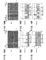
- Figs. 10A and 10B are views showing the relationship between the scale 1 and the photoelectric conversion element array 5 of the absolute rotary encoder according to the third embodiment.
- Fig. 10A is a view showing a state in which codes No. 1 to No. 16 of the code sequence shown in Fig. 9 are read by the photoelectric conversion element array 5a.
- Fig. 10B is a view showing a state in which codes No. 501 to No. 516 of the code sequence shown in Fig. 9 are read by the photoelectric conversion element array 5b.
- each of the photoelectric conversion element arrays 5a and 5b is divided into photoelectric conversion elements (not shown) which are referred to as Ch1, Ch2,..., Ch192 sequentially from the left side.
- Figs. 10C and 10D are views showing the waveform data a and the waveform data b that are output signals reflecting the light amount distribution 6 output from the photoelectric conversion element arrays 5a and 5b, respectively. Ch numbers of the photoelectric conversion element array are plotted along the abscissa, and the values of the output signal reflecting the light amount distribution are plotted along the ordinate.
- the code sequence shown in Fig. 9 includes cyclic codes in which the codes at the positions of 180° rotational symmetry on the scale 1 are inverted.
- periodic signals in which the change in the grayscale reflecting the information of the absolute codes is inverted are output.
- waveform data a and waveform data b These waveform data will be referred to as waveform data a and waveform data b, respectively.
- Fig. 10E shows data (a + b) obtained by adding the waveform data a and b for each Ch. This data is a periodic signal in which the amplitude of the waveform data a or b is unified.
- Fig. 10F shows data (a - b) obtained by subtracting the waveform data b from the waveform data a for each Ch.
- the difference between the grayscales representing codes 2, 1, and 0 is twice as large as the output signals shown in Figs. 10C and 10D . This indicates that the robustness of the code determination signal is improved by the simple subtraction.
- Signal processing of the signal obtained as shown in Fig. 10E can be performed as in the first embodiment.
- Fig. 11 is a graph that enlarges the code determination data obtained as shown in Fig. 10F .
- the code determination data is negative when the code corresponding to the detector 5a is 0, the code determination data is 0 when the code is 1, and the code determination data is positive when the code is 2 because of the relationship between codes and transmittances.
- the codes 0, 1, and 2 can be determined.
- the code determination result shown in Fig. 11 is 0002200100001010.
- an accurate absolute rotary encoder having an arrangement of light calculation load can be implemented.
- An example of ternary codes has been described.
- absolute codes having an arbitrary number of grayscales can be formed on the disc by deciding the location of codes and the correspondence relationship between codes and transmittances such that a periodic signal having a predetermined amplitude is obtained by adding two periodic signals of different grayscales.
- the absolute codes can be demodulated by appropriately deciding the thresholds from the location of codes and the correspondence relationship between codes and transmittances.
- the sets 3a and 3b each including the light source 4 and the photoelectric conversion element array 5 are located so as to have two-fold rotational symmetry, that is, shifted by 180° with respect to the rotation axis 2 of the scale 1.
- a location that further increases the number of sets of the light source 4 and the photoelectric conversion element array 5 is also possible.
- sets 3a to 3c each including a light source 4 and a photoelectric conversion element array 5 are located so as to have three-fold rotational symmetry with respect to a rotation axis 2 of a scale 1 will be described. As shown in Fig.
- an absolute rotary encoder includes the scale 1, the three detecting devices 3 each including the light source 4 and the photoelectric conversion element array 5, and a signal processor P.
- the scale 1 is configured to be rotatable about the rotation axis 2.
- a plurality of marks that form an encoder pattern are radially arrayed on the scale 1.
- the scale 1 has a structure in which non-transmissive marks 1b are located as reference marks, and transmissive marks 1a, first semi-transmissive marks 1c, and second semi-transmissive marks 1d serving as code marks are arrayed between the non-transmissive marks 1b, thereby embedding absolute codes.
- the transmittances of the transmissive marks 1a, the non-transmissive marks 1b, the first semi-transmissive marks 1c, and the second semi-transmissive marks 1d can be set to, for example, 60%, 5%, 40%, and 20%, respectively. Then, the transmissive mark 1a can represent "2", the first semi-transmissive mark can represent "1", and the second semi-transmissive mark can represent "0".
- a code sequence shown in Fig. 13 includes three values 0, 1, and 2.
- the codes are arrayed such that a periodic signal having a predetermined amplitude is obtained by adding three periodic signals obtained from three photoelectric conversion element arrays 5a to 5c and having a change in the grayscale.
- the code sequence is created such that all sums of three codes at the positions of three-fold rotational symmetry with respect to the rotation center of the scale 1 become 3 based on the above-described correspondence relationship between codes and transmittances.
- the number of pulses needs to be a multiple of 3, and is set to 999 here.
- a corresponding code in area 2 When a code in area 1 is 2, a corresponding code in area 2 is 0, and a corresponding code in area 3 is 1.
- the codes of the code sequence shown in Fig. 13 are numbered No. 1, No. 2, No. 3,... from the first code.
- Fig. 14 shows an example of codes No. 1 to No. 16, codes No. 334 to No. 349, and codes No. 667 to No. 682.
- the code sequences shown in Fig. 14 also form 16-bit cyclic codes. That is, in this code sequence, all code sequences of 16-bit consecutive codes do not have the same code sequence.
- Figs. 15A, 15B, and 15C are views showing the relationship between the scale 1 and the photoelectric conversion element arrays 5a to 5c of the absolute rotary encoder according to the present invention.
- Fig. 15A is a view showing a state in which codes No. 1 to No. 16 of the code sequence shown in Fig. 14 are read by the photoelectric conversion element array 5a.
- Fig. 15B is a view showing a state in which codes No. 334 to No. 349 of the code sequence shown in Fig. 14 are read by the photoelectric conversion element array 5b.
- Fig. 15C is a view showing a state in which codes No. 667 to No. 682 of the code sequence shown in Fig. 14 are read by the photoelectric conversion element array 5c.
- the white, black, crosshatched, and hatched portions in Figs. 15A, 15B, and 15C represent the transmissive marks 1a, the non-transmissive marks 1b, the first semi-transmissive marks 1c, and the second semi-transmissive marks 1d, respectively.
- the photoelectric conversion element array 5a is divided into light-receiving elements (not shown) which are referred to as Ch1, Ch2,..., Ch192 sequentially from the left side.
- the light-receiving elements are referred to as Ch1, Ch2,..., Ch192.
- Figs. 15D, 15E, and 15F are views showing output signals reflecting a light amount distribution 6 output from the photoelectric conversion element arrays 5a, 5b, and 5c, respectively. Ch numbers of the photoelectric conversion element array are plotted along the abscissa, and the values of the output signal reflecting the light amount distribution are plotted along the ordinate.
- the code sequence shown in Fig. 14 includes codes located at the positions of three-fold rotational symmetry on the scale 1 in accordance with the above-described rule. Hence, in Figs. 15D, 15E, and 15F , periodic signals having a change in the grayscale reflecting the information of the absolute codes are output.
- waveform data a the waveform data shown in Fig. 15E will be referred to as waveform data b
- waveform data c the waveform data shown in Fig. 15F
- Fig. 15G shows data (a + b + c) obtained by adding the waveform data a , b, and c for each Ch.
- the waveform data b and c are subtracted for the waveform data a for each Ch.
- Fig. 15H shows the difference data (a - b - c).
- a periodic signal having a predetermined amplitude is obtained, as shown in Fig. 15G .
- the difference signal in the difference signal, the difference between the grayscales representing codes 2, 1, and 0 is twice as large as the output signals shown in Figs. 15D, 15E, and 15F . This indicates that the robustness of the code determination signal is improved by the simple subtraction.
- Signal processing of the signal obtained as shown in Fig. 15G can be performed as in the first embodiment.
- Signal processing of the signal obtained as shown in Fig. 15H can be performed as in the third embodiment.
- Thresholds used for code determination and codes to be determined by the thresholds are decided based on the correspondence relationship between codes and transmittances, the location relationship of codes on the scale 1, and the method of combining the data that have undergone subtraction.
- 60% is set for a value "2”
- 40% is set for a value "1”
- 20% is set for a value "0”, as described above.
- location relationship of codes when a value in area 1 is "0", a corresponding value in area 2 is "1", and a corresponding value in area 3 is "2".
- a value in area 1 is "1
- a corresponding value in area 2 is "2”
- a corresponding value in area 3 is "0".
- a corresponding value in area 2 is "0"
- a corresponding value in area 3 is "1”.
- the waveform data b and the waveform data c are subtracted from the waveform data a for each Ch.
- three types of amplitudes are obtained by subtraction.
- the smallest value represents that the value in area 1 is 0, the second smallest value represents that the value in area 1 is 1, and the largest value represents that the value in area 1 is 2.
- the thresholds are decided so as to allow these amplitudes to be discriminated, and a value to be determined by the thresholds is also decided.
- Fig. 16 is a graph that enlarges the code determination data shown in Fig. 15H .
- three types of code determination data can be obtained.
- the code determination result is 0002200100001010.
- the three photoelectric conversion element arrays 5 are located at the positions of three-fold rotational symmetry with respect to the rotation axis 2.
- a plurality of photoelectric conversion element arrays 5 including four or more arrays may be located at the positions of multi-fold rotational symmetry with respect to the rotation axis 2.
- some of the transmissive marks 1a are replaced with the semi-transmissive marks 1c based on the incremental pattern of the transmissive marks 1a and the non-transmissive marks 1b of the scale 1, thereby embedding absolute codes by locating the transmissive marks 1a and the semi-transmissive marks 1c.
- the absolute codes may be embedded by locating the non-transmissive marks 1b and the semi-transmissive marks 1c.
- the transmissive marks 1a, the non-transmissive marks 1b, and the semi-transmissive marks 1c the transmittance is changed.
- the transmissive marks 1a and the non-transmissive marks 1b may be formed by changing the area of the transparent portion, for example, by making the hatching or grating narrow or wide.
- an arrangement of a transmissive encoder is employed.
- an arrangement of a reflective encoder may be employed.
- the reflective type based on the incremental pattern of reflective marks and non-reflective marks of the scale 1, which reflect light in different amounts, some of the reflective marks may be replaced with semi-reflective marks.
- an example in which a diverging optical system using a point light source is employed has been described.
- an arrangement using parallel light or converging light using a lens may be employed. In this case, since the relationship between the pitch of the pattern on the scale 1 and the pitch of the light amount distribution on the photoelectric conversion element array 5 may be different from that in the above embodiments, the pattern pitch and the size of the photoelectric conversion element array 5 are appropriately selected.
- the number N of divisions other than 12 may be employed in consideration of the necessary accuracy and the availability of the photoelectric conversion element array 5.
- An example in which the processor P executes phase calculation and absolute position calculation in parallel, as shown in Fig. 6 has been described. However, these processes may be executed serially. For example, a procedure of performing phase calculation first and then calculating the peak value of a signal from the obtained phase information and determining codes may be employed.
- a plurality of arrays of encoder patterns 1a and 1b may be located at an interval on the cylindrical surface 1 of a cylindrical member in a direction parallel to the axis 2.
- the two photoelectric conversion element arrays 5a and 5b detect signals modulated by the encoder patterns 1a and 1b on the cylindrical surface, respectively.
- an example in which the two photoelectric conversion element arrays 5 are placed at the positions of 180° rotational symmetry or an example in which three photoelectric conversion element arrays are placed at the positions of three-fold rotational symmetry has been described.
- the arrangement that places the plurality of photoelectric conversion element arrays 5 at the positions of rotational symmetry may be regarded as one unit, and a plurality of units may be placed.
- cyclic codes of a pseudo-random number sequence are employed as absolute codes.
- a so-called synchronization sequence that sequentially locates absolute codes and a code representing the start of the codes as one set may be used.
- an absolute rotary encoder using the optical detecting device 3 has been described.
- the present invention is also applicable to a magnetic absolute rotary encoder using a scale 1 formed by providing a magnetic material on the outer surface of a rotating drum and forming S- and N-poles at a predetermined interval by magnetization, and an MR sensor that detects a change in a magnetic field from the scale 1.
- the present invention is also applicable to an absolute linear encoder including a plurality of detectors 5a and 5b located at an interval, and a plurality of arrays of scales 1a and 1b each including a plurality of types of marks arrayed on a plate along a line, as shown in Fig. 18 .
- the plurality of types of marks are located on the scale 1 such that the sum of signal strengths modulated by two marks located on the scale 1 at the same interval as that of the two detecting devices becomes constant.
Landscapes
- Physics & Mathematics (AREA)
- General Physics & Mathematics (AREA)
- Optical Transform (AREA)
- Transmission And Conversion Of Sensor Element Output (AREA)
Applications Claiming Priority (1)
| Application Number | Priority Date | Filing Date | Title |
|---|---|---|---|
| JP2014136215A JP2016014574A (ja) | 2014-07-01 | 2014-07-01 | アブソリュートエンコーダ |
Publications (2)
| Publication Number | Publication Date |
|---|---|
| EP2963393A1 true EP2963393A1 (de) | 2016-01-06 |
| EP2963393B1 EP2963393B1 (de) | 2019-05-01 |
Family
ID=53491251
Family Applications (1)
| Application Number | Title | Priority Date | Filing Date |
|---|---|---|---|
| EP15001887.7A Not-in-force EP2963393B1 (de) | 2014-07-01 | 2015-06-25 | Absolutcodierer |
Country Status (3)
| Country | Link |
|---|---|
| US (1) | US9880028B2 (de) |
| EP (1) | EP2963393B1 (de) |
| JP (1) | JP2016014574A (de) |
Cited By (2)
| Publication number | Priority date | Publication date | Assignee | Title |
|---|---|---|---|---|
| CN105675030A (zh) * | 2016-03-23 | 2016-06-15 | 北京天诚同创电气有限公司 | 用于绝对值编码器的测量方法和装置 |
| CN111102947A (zh) * | 2018-10-26 | 2020-05-05 | 德马吉森精机有限公司 | 位置检测装置和输送装置 |
Families Citing this family (3)
| Publication number | Priority date | Publication date | Assignee | Title |
|---|---|---|---|---|
| RU2645880C1 (ru) * | 2017-01-17 | 2018-02-28 | Федеральное государственное бюджетное образовательное учреждение высшего образования "Тульский государственный университет" (ТулГУ) | Абсолютный оптический однооборотный угловой энкодер |
| US10502593B1 (en) * | 2018-06-07 | 2019-12-10 | Philip M. Johnson | Linear and rotary multitrack absolute position encoder and methods using the same |
| WO2022044323A1 (ja) * | 2020-08-31 | 2022-03-03 | 三菱電機株式会社 | アブソリュートエンコーダ |
Citations (4)
| Publication number | Priority date | Publication date | Assignee | Title |
|---|---|---|---|---|
| EP1329696A1 (de) * | 2002-01-17 | 2003-07-23 | Dr. Johannes Heidenhain GmbH | Positionsmesseinrichtung mit Masstab |
| JP2012037392A (ja) | 2010-08-06 | 2012-02-23 | Canon Inc | アブソリュートエンコーダ |
| US20120153135A1 (en) * | 2010-12-15 | 2012-06-21 | Canon Kabushiki Kaisha | Absolute rotary encoder |
| DE102012212767A1 (de) * | 2012-07-20 | 2014-01-23 | Dr. Johannes Heidenhain Gmbh | Positionsmesseinrichtung |
Family Cites Families (7)
| Publication number | Priority date | Publication date | Assignee | Title |
|---|---|---|---|---|
| JP2009047595A (ja) * | 2007-08-21 | 2009-03-05 | Mitsutoyo Corp | 絶対位置測長型エンコーダ |
| US7557340B2 (en) * | 2007-10-07 | 2009-07-07 | Avago Technologies Ecbu Ip (Singapore) Pte. Ltd. | Shaft-mounted detector for optical encoder having an aperture through the detector for receiving a rotary shaft of a motor |
| DE102007061287A1 (de) * | 2007-12-19 | 2009-06-25 | Dr. Johannes Heidenhain Gmbh | Positionsmesseinrichtung und Verfahren zur absoluten Positionsbestimmung |
| DE102008022027A1 (de) * | 2008-05-02 | 2009-11-05 | Dr. Johannes Heidenhain Gmbh | Positionsmesseinrichtung |
| JP5701496B2 (ja) * | 2009-11-20 | 2015-04-15 | オリンパス株式会社 | 光学式信号出力装置の信号処理装置及び光学式変位検出装置 |
| DE102012207656A1 (de) * | 2012-05-08 | 2013-11-14 | Dr. Johannes Heidenhain Gmbh | Positionsmesseinrichtung und Verfahren zum Betreiben der Positionsmesseinrichtung |
| JP6168762B2 (ja) * | 2012-12-14 | 2017-07-26 | キヤノン株式会社 | アブソリュートエンコーダ |
-
2014
- 2014-07-01 JP JP2014136215A patent/JP2016014574A/ja active Pending
-
2015
- 2015-06-25 EP EP15001887.7A patent/EP2963393B1/de not_active Not-in-force
- 2015-06-30 US US14/754,921 patent/US9880028B2/en not_active Expired - Fee Related
Patent Citations (5)
| Publication number | Priority date | Publication date | Assignee | Title |
|---|---|---|---|---|
| EP1329696A1 (de) * | 2002-01-17 | 2003-07-23 | Dr. Johannes Heidenhain GmbH | Positionsmesseinrichtung mit Masstab |
| JP2012037392A (ja) | 2010-08-06 | 2012-02-23 | Canon Inc | アブソリュートエンコーダ |
| US20120153135A1 (en) * | 2010-12-15 | 2012-06-21 | Canon Kabushiki Kaisha | Absolute rotary encoder |
| JP2012127818A (ja) | 2010-12-15 | 2012-07-05 | Canon Inc | アブソリュートロータリーエンコーダ |
| DE102012212767A1 (de) * | 2012-07-20 | 2014-01-23 | Dr. Johannes Heidenhain Gmbh | Positionsmesseinrichtung |
Cited By (4)
| Publication number | Priority date | Publication date | Assignee | Title |
|---|---|---|---|---|
| CN105675030A (zh) * | 2016-03-23 | 2016-06-15 | 北京天诚同创电气有限公司 | 用于绝对值编码器的测量方法和装置 |
| CN105675030B (zh) * | 2016-03-23 | 2017-10-17 | 北京天诚同创电气有限公司 | 用于绝对值编码器的测量方法和装置 |
| CN111102947A (zh) * | 2018-10-26 | 2020-05-05 | 德马吉森精机有限公司 | 位置检测装置和输送装置 |
| US11906333B2 (en) | 2018-10-26 | 2024-02-20 | Dmg Mori Co., Ltd. | Position detection device and conveyance device |
Also Published As
| Publication number | Publication date |
|---|---|
| EP2963393B1 (de) | 2019-05-01 |
| US9880028B2 (en) | 2018-01-30 |
| US20160003645A1 (en) | 2016-01-07 |
| JP2016014574A (ja) | 2016-01-28 |
Similar Documents
| Publication | Publication Date | Title |
|---|---|---|
| US8785838B2 (en) | Absolute rotary encoder | |
| EP2416126B1 (de) | Absolutkodierer | |
| CN100516780C (zh) | 采用串联多比特内插子编码器的绝对编码器 | |
| EP2466267B1 (de) | Absolutdrehcodierer | |
| US9880028B2 (en) | Absolute encoder | |
| EP2778623A2 (de) | Positionsmess-, Linsenvorrichtung, Bildaufnahmesystem und Maschinenwerkzeugapparat | |
| US10209104B2 (en) | Absolute encoder, processing method, program, driving apparatus, and industrial machine | |
| US9810554B2 (en) | Position measuring instrument | |
| EP2733469B1 (de) | Messvorrichtung, Messverfahren, und Absolutpositionsgeber | |
| JP7203584B2 (ja) | アブソリュートロータリエンコーダ | |
| WO2014132631A1 (en) | Absolute encoder | |
| US9322675B2 (en) | Absolute encoder and method of obtaining absolute position by a plurality of quantized data based on a plurality of extrema | |
| JP2016223978A (ja) | アブソリュートエンコーダ | |
| JP5974154B2 (ja) | ロータリーエンコーダ |
Legal Events
| Date | Code | Title | Description |
|---|---|---|---|
| PUAI | Public reference made under article 153(3) epc to a published international application that has entered the european phase |
Free format text: ORIGINAL CODE: 0009012 |
|
| AK | Designated contracting states |
Kind code of ref document: A1 Designated state(s): AL AT BE BG CH CY CZ DE DK EE ES FI FR GB GR HR HU IE IS IT LI LT LU LV MC MK MT NL NO PL PT RO RS SE SI SK SM TR |
|
| AX | Request for extension of the european patent |
Extension state: BA ME |
|
| RIN1 | Information on inventor provided before grant (corrected) |
Inventor name: UOZUMI, TAKAYUKI Inventor name: OGASAWARA, MAKIKO |
|
| 17P | Request for examination filed |
Effective date: 20160706 |
|
| RBV | Designated contracting states (corrected) |
Designated state(s): AL AT BE BG CH CY CZ DE DK EE ES FI FR GB GR HR HU IE IS IT LI LT LU LV MC MK MT NL NO PL PT RO RS SE SI SK SM TR |
|
| STAA | Information on the status of an ep patent application or granted ep patent |
Free format text: STATUS: EXAMINATION IS IN PROGRESS |
|
| 17Q | First examination report despatched |
Effective date: 20180315 |
|
| GRAP | Despatch of communication of intention to grant a patent |
Free format text: ORIGINAL CODE: EPIDOSNIGR1 |
|
| STAA | Information on the status of an ep patent application or granted ep patent |
Free format text: STATUS: GRANT OF PATENT IS INTENDED |
|
| INTG | Intention to grant announced |
Effective date: 20181122 |
|
| GRAS | Grant fee paid |
Free format text: ORIGINAL CODE: EPIDOSNIGR3 |
|
| GRAA | (expected) grant |
Free format text: ORIGINAL CODE: 0009210 |
|
| STAA | Information on the status of an ep patent application or granted ep patent |
Free format text: STATUS: THE PATENT HAS BEEN GRANTED |
|
| AK | Designated contracting states |
Kind code of ref document: B1 Designated state(s): AL AT BE BG CH CY CZ DE DK EE ES FI FR GB GR HR HU IE IS IT LI LT LU LV MC MK MT NL NO PL PT RO RS SE SI SK SM TR |
|
| RAP1 | Party data changed (applicant data changed or rights of an application transferred) |
Owner name: CANON KABUSHIKI KAISHA |
|
| REG | Reference to a national code |
Ref country code: GB Ref legal event code: FG4D |
|
| REG | Reference to a national code |
Ref country code: CH Ref legal event code: EP Ref country code: AT Ref legal event code: REF Ref document number: 1127551 Country of ref document: AT Kind code of ref document: T Effective date: 20190515 |
|
| REG | Reference to a national code |
Ref country code: DE Ref legal event code: R096 Ref document number: 602015029135 Country of ref document: DE |
|
| REG | Reference to a national code |
Ref country code: IE Ref legal event code: FG4D |
|
| REG | Reference to a national code |
Ref country code: NL Ref legal event code: MP Effective date: 20190501 |
|
| REG | Reference to a national code |
Ref country code: LT Ref legal event code: MG4D |
|
| PG25 | Lapsed in a contracting state [announced via postgrant information from national office to epo] |
Ref country code: ES Free format text: LAPSE BECAUSE OF FAILURE TO SUBMIT A TRANSLATION OF THE DESCRIPTION OR TO PAY THE FEE WITHIN THE PRESCRIBED TIME-LIMIT Effective date: 20190501 Ref country code: HR Free format text: LAPSE BECAUSE OF FAILURE TO SUBMIT A TRANSLATION OF THE DESCRIPTION OR TO PAY THE FEE WITHIN THE PRESCRIBED TIME-LIMIT Effective date: 20190501 Ref country code: PT Free format text: LAPSE BECAUSE OF FAILURE TO SUBMIT A TRANSLATION OF THE DESCRIPTION OR TO PAY THE FEE WITHIN THE PRESCRIBED TIME-LIMIT Effective date: 20190901 Ref country code: NO Free format text: LAPSE BECAUSE OF FAILURE TO SUBMIT A TRANSLATION OF THE DESCRIPTION OR TO PAY THE FEE WITHIN THE PRESCRIBED TIME-LIMIT Effective date: 20190801 Ref country code: AL Free format text: LAPSE BECAUSE OF FAILURE TO SUBMIT A TRANSLATION OF THE DESCRIPTION OR TO PAY THE FEE WITHIN THE PRESCRIBED TIME-LIMIT Effective date: 20190501 Ref country code: SE Free format text: LAPSE BECAUSE OF FAILURE TO SUBMIT A TRANSLATION OF THE DESCRIPTION OR TO PAY THE FEE WITHIN THE PRESCRIBED TIME-LIMIT Effective date: 20190501 Ref country code: FI Free format text: LAPSE BECAUSE OF FAILURE TO SUBMIT A TRANSLATION OF THE DESCRIPTION OR TO PAY THE FEE WITHIN THE PRESCRIBED TIME-LIMIT Effective date: 20190501 Ref country code: LT Free format text: LAPSE BECAUSE OF FAILURE TO SUBMIT A TRANSLATION OF THE DESCRIPTION OR TO PAY THE FEE WITHIN THE PRESCRIBED TIME-LIMIT Effective date: 20190501 Ref country code: NL Free format text: LAPSE BECAUSE OF FAILURE TO SUBMIT A TRANSLATION OF THE DESCRIPTION OR TO PAY THE FEE WITHIN THE PRESCRIBED TIME-LIMIT Effective date: 20190501 |
|
| PGFP | Annual fee paid to national office [announced via postgrant information from national office to epo] |
Ref country code: DE Payment date: 20190830 Year of fee payment: 5 |
|
| PG25 | Lapsed in a contracting state [announced via postgrant information from national office to epo] |
Ref country code: GR Free format text: LAPSE BECAUSE OF FAILURE TO SUBMIT A TRANSLATION OF THE DESCRIPTION OR TO PAY THE FEE WITHIN THE PRESCRIBED TIME-LIMIT Effective date: 20190802 Ref country code: RS Free format text: LAPSE BECAUSE OF FAILURE TO SUBMIT A TRANSLATION OF THE DESCRIPTION OR TO PAY THE FEE WITHIN THE PRESCRIBED TIME-LIMIT Effective date: 20190501 Ref country code: BG Free format text: LAPSE BECAUSE OF FAILURE TO SUBMIT A TRANSLATION OF THE DESCRIPTION OR TO PAY THE FEE WITHIN THE PRESCRIBED TIME-LIMIT Effective date: 20190801 Ref country code: LV Free format text: LAPSE BECAUSE OF FAILURE TO SUBMIT A TRANSLATION OF THE DESCRIPTION OR TO PAY THE FEE WITHIN THE PRESCRIBED TIME-LIMIT Effective date: 20190501 |
|
| REG | Reference to a national code |
Ref country code: AT Ref legal event code: MK05 Ref document number: 1127551 Country of ref document: AT Kind code of ref document: T Effective date: 20190501 |
|
| PG25 | Lapsed in a contracting state [announced via postgrant information from national office to epo] |
Ref country code: IS Free format text: LAPSE BECAUSE OF FAILURE TO SUBMIT A TRANSLATION OF THE DESCRIPTION OR TO PAY THE FEE WITHIN THE PRESCRIBED TIME-LIMIT Effective date: 20190901 |
|
| PG25 | Lapsed in a contracting state [announced via postgrant information from national office to epo] |
Ref country code: DK Free format text: LAPSE BECAUSE OF FAILURE TO SUBMIT A TRANSLATION OF THE DESCRIPTION OR TO PAY THE FEE WITHIN THE PRESCRIBED TIME-LIMIT Effective date: 20190501 Ref country code: AT Free format text: LAPSE BECAUSE OF FAILURE TO SUBMIT A TRANSLATION OF THE DESCRIPTION OR TO PAY THE FEE WITHIN THE PRESCRIBED TIME-LIMIT Effective date: 20190501 Ref country code: EE Free format text: LAPSE BECAUSE OF FAILURE TO SUBMIT A TRANSLATION OF THE DESCRIPTION OR TO PAY THE FEE WITHIN THE PRESCRIBED TIME-LIMIT Effective date: 20190501 Ref country code: MC Free format text: LAPSE BECAUSE OF FAILURE TO SUBMIT A TRANSLATION OF THE DESCRIPTION OR TO PAY THE FEE WITHIN THE PRESCRIBED TIME-LIMIT Effective date: 20190501 Ref country code: RO Free format text: LAPSE BECAUSE OF FAILURE TO SUBMIT A TRANSLATION OF THE DESCRIPTION OR TO PAY THE FEE WITHIN THE PRESCRIBED TIME-LIMIT Effective date: 20190501 Ref country code: CZ Free format text: LAPSE BECAUSE OF FAILURE TO SUBMIT A TRANSLATION OF THE DESCRIPTION OR TO PAY THE FEE WITHIN THE PRESCRIBED TIME-LIMIT Effective date: 20190501 Ref country code: SK Free format text: LAPSE BECAUSE OF FAILURE TO SUBMIT A TRANSLATION OF THE DESCRIPTION OR TO PAY THE FEE WITHIN THE PRESCRIBED TIME-LIMIT Effective date: 20190501 |
|
| REG | Reference to a national code |
Ref country code: CH Ref legal event code: PL |
|
| REG | Reference to a national code |
Ref country code: DE Ref legal event code: R097 Ref document number: 602015029135 Country of ref document: DE |
|
| PG25 | Lapsed in a contracting state [announced via postgrant information from national office to epo] |
Ref country code: IT Free format text: LAPSE BECAUSE OF FAILURE TO SUBMIT A TRANSLATION OF THE DESCRIPTION OR TO PAY THE FEE WITHIN THE PRESCRIBED TIME-LIMIT Effective date: 20190501 Ref country code: SM Free format text: LAPSE BECAUSE OF FAILURE TO SUBMIT A TRANSLATION OF THE DESCRIPTION OR TO PAY THE FEE WITHIN THE PRESCRIBED TIME-LIMIT Effective date: 20190501 |
|
| PLBE | No opposition filed within time limit |
Free format text: ORIGINAL CODE: 0009261 |
|
| STAA | Information on the status of an ep patent application or granted ep patent |
Free format text: STATUS: NO OPPOSITION FILED WITHIN TIME LIMIT |
|
| REG | Reference to a national code |
Ref country code: BE Ref legal event code: MM Effective date: 20190630 |
|
| PG25 | Lapsed in a contracting state [announced via postgrant information from national office to epo] |
Ref country code: TR Free format text: LAPSE BECAUSE OF FAILURE TO SUBMIT A TRANSLATION OF THE DESCRIPTION OR TO PAY THE FEE WITHIN THE PRESCRIBED TIME-LIMIT Effective date: 20190501 |
|
| 26N | No opposition filed |
Effective date: 20200204 |
|
| GBPC | Gb: european patent ceased through non-payment of renewal fee |
Effective date: 20190801 |
|
| PG25 | Lapsed in a contracting state [announced via postgrant information from national office to epo] |
Ref country code: PL Free format text: LAPSE BECAUSE OF FAILURE TO SUBMIT A TRANSLATION OF THE DESCRIPTION OR TO PAY THE FEE WITHIN THE PRESCRIBED TIME-LIMIT Effective date: 20190501 Ref country code: IE Free format text: LAPSE BECAUSE OF NON-PAYMENT OF DUE FEES Effective date: 20190625 |
|
| PG25 | Lapsed in a contracting state [announced via postgrant information from national office to epo] |
Ref country code: LI Free format text: LAPSE BECAUSE OF NON-PAYMENT OF DUE FEES Effective date: 20190630 Ref country code: CH Free format text: LAPSE BECAUSE OF NON-PAYMENT OF DUE FEES Effective date: 20190630 Ref country code: SI Free format text: LAPSE BECAUSE OF FAILURE TO SUBMIT A TRANSLATION OF THE DESCRIPTION OR TO PAY THE FEE WITHIN THE PRESCRIBED TIME-LIMIT Effective date: 20190501 Ref country code: BE Free format text: LAPSE BECAUSE OF NON-PAYMENT OF DUE FEES Effective date: 20190630 Ref country code: LU Free format text: LAPSE BECAUSE OF NON-PAYMENT OF DUE FEES Effective date: 20190625 |
|
| PG25 | Lapsed in a contracting state [announced via postgrant information from national office to epo] |
Ref country code: FR Free format text: LAPSE BECAUSE OF NON-PAYMENT OF DUE FEES Effective date: 20190701 |
|
| PG25 | Lapsed in a contracting state [announced via postgrant information from national office to epo] |
Ref country code: GB Free format text: LAPSE BECAUSE OF NON-PAYMENT OF DUE FEES Effective date: 20190801 |
|
| REG | Reference to a national code |
Ref country code: DE Ref legal event code: R119 Ref document number: 602015029135 Country of ref document: DE |
|
| PG25 | Lapsed in a contracting state [announced via postgrant information from national office to epo] |
Ref country code: DE Free format text: LAPSE BECAUSE OF NON-PAYMENT OF DUE FEES Effective date: 20210101 Ref country code: CY Free format text: LAPSE BECAUSE OF FAILURE TO SUBMIT A TRANSLATION OF THE DESCRIPTION OR TO PAY THE FEE WITHIN THE PRESCRIBED TIME-LIMIT Effective date: 20190501 |
|
| PG25 | Lapsed in a contracting state [announced via postgrant information from national office to epo] |
Ref country code: MT Free format text: LAPSE BECAUSE OF FAILURE TO SUBMIT A TRANSLATION OF THE DESCRIPTION OR TO PAY THE FEE WITHIN THE PRESCRIBED TIME-LIMIT Effective date: 20190501 Ref country code: HU Free format text: LAPSE BECAUSE OF FAILURE TO SUBMIT A TRANSLATION OF THE DESCRIPTION OR TO PAY THE FEE WITHIN THE PRESCRIBED TIME-LIMIT; INVALID AB INITIO Effective date: 20150625 |
|
| PG25 | Lapsed in a contracting state [announced via postgrant information from national office to epo] |
Ref country code: MK Free format text: LAPSE BECAUSE OF FAILURE TO SUBMIT A TRANSLATION OF THE DESCRIPTION OR TO PAY THE FEE WITHIN THE PRESCRIBED TIME-LIMIT Effective date: 20190501 |