EP2963396B1 - Jaugeage de niveau par radar pulsé avec démarrage efficace - Google Patents
Jaugeage de niveau par radar pulsé avec démarrage efficace Download PDFInfo
- Publication number
- EP2963396B1 EP2963396B1 EP15173944.8A EP15173944A EP2963396B1 EP 2963396 B1 EP2963396 B1 EP 2963396B1 EP 15173944 A EP15173944 A EP 15173944A EP 2963396 B1 EP2963396 B1 EP 2963396B1
- Authority
- EP
- European Patent Office
- Prior art keywords
- frequency
- level gauge
- signal
- radar level
- power
- Prior art date
- Legal status (The legal status is an assumption and is not a legal conclusion. Google has not performed a legal analysis and makes no representation as to the accuracy of the status listed.)
- Active
Links
Images


Classifications
-
- G—PHYSICS
- G01—MEASURING; TESTING
- G01F—MEASURING VOLUME, VOLUME FLOW, MASS FLOW OR LIQUID LEVEL; METERING BY VOLUME
- G01F23/00—Indicating or measuring liquid level or level of fluent solid material, e.g. indicating in terms of volume or indicating by means of an alarm
- G01F23/22—Indicating or measuring liquid level or level of fluent solid material, e.g. indicating in terms of volume or indicating by means of an alarm by measuring physical variables, other than linear dimensions, pressure or weight, dependent on the level to be measured, e.g. by difference of heat transfer of steam or water
- G01F23/28—Indicating or measuring liquid level or level of fluent solid material, e.g. indicating in terms of volume or indicating by means of an alarm by measuring physical variables, other than linear dimensions, pressure or weight, dependent on the level to be measured, e.g. by difference of heat transfer of steam or water by measuring the variations of parameters of electromagnetic or acoustic waves applied directly to the liquid or fluent solid material
- G01F23/284—Electromagnetic waves
-
- G—PHYSICS
- G01—MEASURING; TESTING
- G01S—RADIO DIRECTION-FINDING; RADIO NAVIGATION; DETERMINING DISTANCE OR VELOCITY BY USE OF RADIO WAVES; LOCATING OR PRESENCE-DETECTING BY USE OF THE REFLECTION OR RERADIATION OF RADIO WAVES; ANALOGOUS ARRANGEMENTS USING OTHER WAVES
- G01S13/00—Systems using the reflection or reradiation of radio waves, e.g. radar systems; Analogous systems using reflection or reradiation of waves whose nature or wavelength is irrelevant or unspecified
- G01S13/02—Systems using reflection of radio waves, e.g. primary radar systems; Analogous systems
- G01S13/06—Systems determining position data of a target
- G01S13/08—Systems for measuring distance only
- G01S13/10—Systems for measuring distance only using transmission of interrupted, pulse modulated waves
-
- G—PHYSICS
- G01—MEASURING; TESTING
- G01S—RADIO DIRECTION-FINDING; RADIO NAVIGATION; DETERMINING DISTANCE OR VELOCITY BY USE OF RADIO WAVES; LOCATING OR PRESENCE-DETECTING BY USE OF THE REFLECTION OR RERADIATION OF RADIO WAVES; ANALOGOUS ARRANGEMENTS USING OTHER WAVES
- G01S13/00—Systems using the reflection or reradiation of radio waves, e.g. radar systems; Analogous systems using reflection or reradiation of waves whose nature or wavelength is irrelevant or unspecified
- G01S13/88—Radar or analogous systems specially adapted for specific applications
-
- G—PHYSICS
- G01—MEASURING; TESTING
- G01S—RADIO DIRECTION-FINDING; RADIO NAVIGATION; DETERMINING DISTANCE OR VELOCITY BY USE OF RADIO WAVES; LOCATING OR PRESENCE-DETECTING BY USE OF THE REFLECTION OR RERADIATION OF RADIO WAVES; ANALOGOUS ARRANGEMENTS USING OTHER WAVES
- G01S7/00—Details of systems according to groups G01S13/00, G01S15/00, G01S17/00
- G01S7/02—Details of systems according to groups G01S13/00, G01S15/00, G01S17/00 of systems according to group G01S13/00
- G01S7/28—Details of pulse systems
Definitions
- US 2011 /140951 A1 , EP 1 562 051 A2 and US 2013/300595 A1 disclose a pulsed radar level gauge system for determining level in a container.
- Such pulsed radar level gauge systems may have a first oscillator for generating a transmission signal formed by pulses for transmission towards the surface of the product contained in the tank with a transmitted pulse repetition frequency f t , and a second oscillator for generating a reference signal formed by reference pulses with a reference pulse repetition frequency f ref that differs from the transmitted pulse repetition frequency by a given frequency difference ⁇ f.
- This frequency difference ⁇ f is typically in the range of Hz or tens of Hz.
- the transmission signal and the reference signal are usually synchronized to have the same phase. Due to the frequency difference ⁇ f, the phase difference between the transmission signal and the reference signal will gradually increase during the measurement sweep.
- the reflection signal resulting from reflection of the transmission signal at the surface of the product contained in the tank is being correlated with the reference signal, so that an output signal is only produced when a reflected pulse and a reference pulse occur at the same time.
- the time from the start of the measurement sweep to the occurrence of the output signal resulting from the correlation of the reflection signal and the reference signal is a measure of the phase difference between the transmission signal and the reflection signal, which is in turn a time expanded measure of the time-of-flight of the reflected pulses, from which the distance to the surface of the product contained in the tank can be determined.
- the system comprises a radar level gauge circuit configured to generate a transmit signal in the form of a pulse train with a transmit pulse repetition frequency based on the first clock frequency and generate a reference signal in the form of a pulse train with a reference pulse repetition frequency based on the second clock frequency, transmit the transmit signal towards the surface, receive a return signal caused by a reflection of the transmit signal at the surface, and provide a level output based on a relationship between the return signal and the reference signal.
- the system further comprises power management circuitry configured to, in absence of the power-up signal, not power the radar level gauge circuit to provide a level output, and in presence of the power-up signal, power the radar level gauge circuit to provide a level output.
- the objectives are also achieved by a method for measuring the distance to a surface of a material contained in a tank.
- the method comprises the steps of generating a first clock frequency and a second clock frequency, controlling a frequency separation to ensure a predefined frequency separation between the first and second clock frequencies.
- the method further comprises the step of generating a power-up signal when the frequency separation is within a predefined frequency range.
- the present invention allows a radar level gauge system to save power by not providing power to and operating the radar level gauge circuit during such times when the frequency separation would not enable the radar level gauge to provide proper level measurements.
- the expression "not provide power” should, in the context of the present invention, be construed as providing none or insufficient power for the radar level gauge circuit to be able to perform a measurement and/or provide a level output. Thereby, significant power savings can be made while the frequency separation is stabilized.
- the frequency separation evaluation circuit may be configured to compare a detected frequency separation to a predefined threshold value in order to determine a good timing of said frequency separation.
- the term "good timing of the frequency separation” refers to that the frequency separation is sufficiently stable over time and/or that the frequency separation is sufficiently small.
- the frequency separation evaluation circuit will generate the power-up signal in order to activate more parts of the system.
- the frequency separation evaluation circuit and the power management circuitry may be comprised in a single low power circuit separate from said radar level gauge circuit. Thereby, the circuits and components needed for the frequency stabilization phase are efficiently separated from the circuits and components used during the measurement phase.
- the low power circuit may thus be a stand-alone low power FPGA solution or a small micro control unit. Such units are per se known to the person skilled in the art and are cheap and durable.
- the frequency separation evaluation circuit may be configured to be inactive during measurements by the radar level gauge circuit.
- Such a solution will allow for a simple and efficient separation of power division e.g. power management by bypassing the separate low power circuit when applicable, i.e. when measurements are performed.
- the peak power usage during level measurement may be decreased by not activating the circuit and components used during the preparatory phase.
- the power management circuitry may provide power to the radar level gauge circuit for a plurality of consecutive measurements.
- GWR pulsed guided wave radar
- Fig 1 schematically illustrates a level gauge system 1 arranged on top of a tank 2 for determining the filling level of a product 3 contained in the tank 2 using microwaves.
- the level gauge system 1 is therefore in the following referred to as a radar level gauge system or an RLG-system.
- the radar level gauge system 1 comprises a measurement unit 5, a propagating device, here in the form of a horn antenna 6 for propagating microwaves towards a surface 7 of the product 3 contained in the tank 2, and a communication antenna 8 for allowing wireless communication with a remote device.
- a propagating device here in the form of a horn antenna 6 for propagating microwaves towards a surface 7 of the product 3 contained in the tank 2
- a communication antenna 8 for allowing wireless communication with a remote device.
- the radar level gauge system 1 When measuring the filling level of the product 3 contained in the tank 2, the radar level gauge system 1 transmits an electromagnetic transmission signal S T by the antenna 6 towards the surface 7 of the product 3, where the signal is reflected as a surface echo signal S R . The distance between a reference position at the top of the tank 2 and the surface 7 of the product 3 is then determined based on the time-of-flight of the surface echo signal S R (from the radar level gauge system 1 to the surface 7 and back). From this distance and known dimensions of the tank 2, the filling level can be deduced.
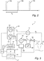
- FIG. 2 A widely used scheme for handling situations where the average energy consumption is important is schematically illustrated in fig 2 .
- filling level determination events 10a-c are separated in time, and between these filling level determination events 10a-c, the level gauge system 1 is in a sleep mode, where parts of the level gauge system that are used to determine the filling level may be turned off.
- This scheme is often referred to as intermittent operation, and the time t u between the filling level determination events defines an update frequency.
- the update frequency can differ for different types of implementations, for a radar level gauge system with no practical limitations to energy provision such as a system being supplied with energy/power by grid electricity the update frequency can be as high as once per second.
- the update frequency can be lower e.g. once per minute or once per 10 minutes or the update frequency can be even lower such as once per hour or once per day (24 hour cycle).
- the design of a radar level gauge system with limited amounts of energy will often be dependent on the required update frequency for the application at hand. For example, harsher safety demands may require a higher update frequency or the update frequency may be set higher by an operator of the system requiring quicker updates of the filling level.
- the limitations can also be imposed due to a low amount of available energy/power for a radar level gauge system being powered by other sources, e.g. a hydrogen fuel cell or a photovoltaic solar cell.
- the various aspects of the present invention provide for efficient start-up of parts of the radar level gauge system in order to conserve power until actual measurements occur. This will be described in further detail below with reference to figures 3 and 4 .
- Fig 3 is a block diagram schematically showing functional components comprised in the level gauge system in fig 1 .
- the exemplary level gauge system 1 comprises a transmitter branch and a receiver branch generally understood to be a radar level gauge circuit.
- a frequency generating circuitry 26 is configured to generate a first and a second clock frequency, used to generate a transmit pulse train and a reference pulse train.
- the frequency generating circuitry comprises a transmit pulse generator 10 for generating a transmit pulse train.
- the pulse repetition frequency of the transmit pulse train is here equal to the first clock frequency.
- the frequency generating circuitry further comprises a reference pulse generator 14, for generating a reference pulse train.
- the pulse repetition frequency of the reference pulse train is here equal to the second clock frequency.
- the transmit pulse generator 10 and the reference pulse generator 14 are typically voltage controlled oscillators, and may be e.g. crystal oscillators. If higher pulse repletion frequencies are required than the oscillators generate, additional circuitry may be provided to multiply the first and second clock frequencies.
- the pulse repetition frequencies are typically in the order of MHz. It should also be noted that the pulses are very short, on the order of nanoseconds.
- the transmitter branch further comprises a first RF-source 11, and a transmitting antenna 12, and the receiver branch further comprises a second RF-source 15, mixing circuitry 16, and a receiving antenna 17.
- the receiver branch further comprises a low noise amplifier 18 for amplifying the signals received by the receiving antenna 17.
- the receiving antenna 17 and the transmitting antenna 12 are embodied as one single antenna.
- the pulses provided by the transmission pulse generator 10 are modulated by the first RF-source 11 to form a transmit signal S T in the form of a sequence of transmission pulses (short "packets" of microwave energy) which is radiated towards the surface 7 of the product by the transmitting antenna 12.
- the modulation frequency is typically in the order of GHz.
- the pulses of the transmit signal S T and the pulses of the reference signal S REF may advantageously be in phase at the start of a measurement sweep so that the time until there is correlation between the reference signal S REF and the reflected signal S R together with the difference frequency ⁇ f can be used to determine the time-of-flight of the reflected signal S R . The time-of-flight is then used to determine the filling level.
- the reference signal S REF and the reflected signal S R are time correlated to form a tank signal S m , which is provided to the microprocessor 20, where the distance to the surface 7 of the product 6 is determined based on the measurement signal S m .
- the "sampling" performed in the mixing circuitry 16 is sometimes referred to as “hardware sampling” and should not be confused with the sampling done during the subsequent signal processing. The details of the sampling done in the mixing circuitry 16 further depend on the type of pulses.
- the frequency regulator 21 is also connected to a frequency separation evaluation circuit 23 which is arranged to generate a power-up signal when said frequency separation is within a predefined frequency range, i.e. the frequency difference ⁇ f.
- the radar level gauge system 1 also comprises a power management circuitry 24 configured to provide power to the radar level gauge circuit, i.e. transmitter and receiver branch, in response to a power-up signal from the frequency separation evaluation circuit 23.
- the level gauge system 1 additionally comprises a power source 25 connected to the frequency generating circuitry 26, the frequency regulator 21, the frequency separation evaluation circuit 23 and the power management circuitry 24.
- the power source 25 could be a 4-20 mA control loop or a battery as discussed above. Note that the power source 25 can be the sole provider of power for the system and no remote power is present, such as in the case of a battery.
- the power management circuitry 24 In absence of the power-up signal, the power management circuitry 24 is configured to not power the radar level gauge circuit to provide a level output. In presence of the power-up signal, the power management circuitry 24 is configured to power the radar level gauge circuit to provide a level output.
- the power management circuitry 24 is further connected to a power distribution unit 22, and the power distribution unit 22 is connected to the microprocessor 20, and to various parts of the level gauge system 1 for supplying power during measurement to those components comprised in the radar level gauge circuit.
- the power distribution unit 22 In the exemplary embodiment that is schematically illustrated in fig 3 , the power distribution unit 22 is connected to the first RF-source 11, the second RF-source 15 and the low noise amplifier 18 between the receiving antenna 17 and the sampling circuitry 16.
- the peak power usage can be further reduced by inactivating the frequency separation evaluation circuit 23 during measurements.
- the frequency separation evaluation circuit 23 controlling the power-up circuit 24 can then be comprised in a single low power circuit 27 separate from the radar level gauge circuit.
- the single low power circuit 27 could be any type of stand-alone circuitry such as an FPGA or small MCU.
- the elements of the power distribution unit 22 and the microprocessor 20 are shown as separate units typically implemented in hardware, they can also form part of an integrated unit. At least some portions of the microprocessor 20 are typically embodied by software modules executed by an embedded processor. The invention is not restricted to this particular realization, and any implementation found suitable to realize the herein described functionality may be contemplated.
- the frequency generating circuitry 26 is controlled by the frequency regulator 21 to achieve a correct frequency separation and the frequency separation evaluation circuit 23 will monitor the frequency separation. After a sufficient amount of regulation attempt by the frequency regulator 21 the frequency separation is acceptable and the frequency separation evaluation circuit 23 will then generate a power-up signal to the power-up circuitry 24, which will then send power to the power management circuit 22 which will enable level measurements by the radar level circuit as described above in conjunction with fig 1 .
- the microprocessor 20 After determining the distance to the surface 7 of the product 6 the microprocessor 20 will then typically send that data through a connection with the 4-20mA control loop (not shown) or through above discussed wireless connections (not shown). As an alternative, the level measurement may also be shown on an indicator locally and thus also possibly stored locally in some sort of digital storage means (not shown).
- An alternative to further reduce the peak power usage of the frequency regulator 21 can be configured not provide any regulation during measurements.
- the control signals applied to the transmission pulse generator 10 and the reference pulse generator 14 will then remain constant, and the pulse generators will continue to provide the same frequencies.
- the Q-value of the transmission pulse generator 10 and the reference pulse generator 14 need to be high enough for one or several measurements without continuous regulation from the frequency regulator 21.
- An additional alternative to further reduce the power usage of the radar level gauge system comprises configuring power management circuitry 24 and the power distribution unit 22 to, as soon as a measurement is performed and received, shut off power to all components except the microprocessor 20 until the level output has been sent or stored. After the level output has been sent or stored, as is described above, power is also shut off from the microprocessor 20.
- a first step S1 comprises generating a first clock frequency and a second clock frequency.
- a second step S2 comprises controlling a frequency separation to ensure a predefined frequency separation between the first and second clock frequencies.
- a power-up signal is generated when the frequency separation is within a predefined frequency range. If the frequency separation is not within the predefined frequency range, the method will return to step S2 and continue to control the frequency separation. If the frequency separation is within the predefined frequency range, the power-up signal is generated.
- Steps S1-S3 can be referred to as an initial frequency stabilization procedure which ensures a stable separation frequency.
- a radar level gauge circuit is powered if the power up signal is present. Hence, in the absence of said power-up signal, the radar level gauge circuit is not powered and in the presence of the power-up signal power is provided to the radar level gauge circuit.
- the power provided to the radar level gauge circuit will in a fifth step S5 enable the radar level gauge circuit to generate and transmit a transmit signal S T towards said surface.
- the transmit signal S T being a pulse train with a transmit pulse repetition frequency based on said first clock frequency.
- the transmit signal S T is transmitted towards the surface 7 of the product 3 contained in the tank 2.
- a reflected return signal S R resulting from reflection of the transmission signal S T at the surface 7 is received.
- a seventh step S7 the return signal S R is time correlated with a reference signal in the form of a pulse train with a reference pulse repetition frequency based on the second clock frequency. The result is a time expanded measurement signal S m .
- the filling level is determined based on the measurement signal S m and provided as a level output.
- Steps S4-S8 can be referred to as a measurement cycle, performed only when a stable separation frequency has been established.
Landscapes
- Physics & Mathematics (AREA)
- Engineering & Computer Science (AREA)
- Radar, Positioning & Navigation (AREA)
- Remote Sensing (AREA)
- General Physics & Mathematics (AREA)
- Electromagnetism (AREA)
- Computer Networks & Wireless Communication (AREA)
- Thermal Sciences (AREA)
- Fluid Mechanics (AREA)
- Measurement Of Levels Of Liquids Or Fluent Solid Materials (AREA)
- Radar Systems Or Details Thereof (AREA)
Claims (21)
- Système d'indicateur radar de niveau à impulsions (1) pour mesurer une distance par rapport à une surface (7) d'un matériau (3) contenu dans un réservoir (2), ledit système (1) comprenant :un circuit de génération de fréquence (26) adapté pour générer une première fréquence d'horloge et une seconde fréquence d'horloge ;un régulateur de fréquence (21) configuré pour commander une séparation de fréquence entre la première et la seconde fréquence d'horloge dans la direction d'un point de consigne de séparation de fréquence ;un circuit d'évaluation de séparation de fréquence (23) agencé pour générer un signal de mise sous tension lorsque ladite séparation de fréquence est à l'intérieur d'une plage de fréquence prédéfinie ;un circuit d'indicateur radar de niveau configuré pour :- générer un signal d'émission sous la forme d'un train d'impulsions avec une fréquence de répétition d'impulsions d'émission sur la base de ladite première fréquence d'horloge ;- générer un signal de fréquence de la forme impulsions avec une fréquence de répétition d'impulsions de référence basée sur ladite seconde fréquence horloge ;- émettre ledit signal d'émission dans la direction de la surface ;- recevoir un signal de retour causé par une action dudit signal d'émission au niveau de ladite surface ;- fournir une sortie de niveau sur la base d'une relation entre ledit signal de retour et le signal de référence ; etun circuit de gestion d'alimentation électrique (24) configuré pour :en l'absence dudit signal de mise sous tension, ne pas alimenter ledit circuit indicateur radar de niveau pour sortir une sortie de niveau, eten présence dudit signal de mise sous tension, alimenter ledit circuit indicateur radar de niveau pour produire une sortie de niveau.
- Système indicateur radar de niveau (1) selon la revendication 1, comprenant en outre un moyen de mémorisation pour mémoriser une valeur seuil préréglée de variation de séparation de fréquence, et dans lequel ledit circuit d'évaluation de séparation de fréquence (23) est configuré pour générer ledit signal de mise de tension lorsque une variation de ladite séparation de fréquence est plus petite qu'une valeur seuil prédéfinie.
- Système indicateur radar de niveau (1) selon la revendication 1 ou 2, dans lequel ledit circuit d'évaluation de séparation de fréquence (23) est connectée audit régulateur de fréquence (21) et agencé pour déterminer ladite séparation de fréquence sur la base d'une condition dudit régulateur de fréquence.
- Système indicateur radar de niveau (1) selon une quelconque des revendications précédentes, dans lequel ledit régulateur de fréquence (21) comprend un comparateur pour fournir un signal d'erreur indiquant une différence entre une séparation de fréquence actuelle et ledit point de consigne de séparation de fréquence, et dans lequel ledit circuit d'évaluation de séparation de fréquence (23) est agencé pour générer ledit signal de mise sous tension lorsque ledit signal d'erreur est au-dessous de ladite valeur seuil prédéfinie.
- Système indicateur radar de niveau (1) selon une quelconque des revendications précédentes, dans lequel ledit circuit de génération de fréquence (26) comprend au moins un oscillateur commandé par tension (10,14).
- Système indicateur radar de niveau (1) selon une quelconque des revendications précédentes, comprenant en outre une boucle de commande à deux fils, pour fournir une alimentation électrique de circuit indicateur radar de niveau.
- Système indicateur radar de niveau (1) selon une quelconque des revendications 1-5, sans aucune connexion à n'importe quelle alimentation électrique distante et comprenant un magasin d'alimentation électrique interne (25) comme seul moyen pour fournir une alimentation électrique de circuit indicateur radar de niveau.
- Système indicateur radar de niveau (1) selon une quelconque des revendications précédentes, dans lequel ledit circuit d'évaluation de séparation de fréquence (23) et ledit circuit de gestion alimentation électrique (24) sont compris dans un circuit d'alimentation basse unique (27) séparé dudit circuit indicateur radar de niveau.
- Circuit indicateur radar de niveau (1) selon la revendication 8, dans lequel ledit circuit d'alimentation basse et une à une solution FPGA d'alimentation basse autonome et une unité de micro commande.
- Système indicateur radar de niveau (1) selon une quelconque des revendications précédentes, dans lequel ledit circuit d'évaluation de séparation de fréquence (23) est configuré pour être inactif pendant les mesures par le circuit indicateur radar de niveau.
- Système indicateur radar de niveau (1) selon une quelconque des revendications précédentes, dans lequel ledit circuit de gestion d'alimentation électrique (24) fournit une alimentation électrique audit circuit indicateur radar de niveau ou une pluralité de mesures consécutives à chaque fois qu'un signal de mise sous tension est présent.
- Système indicateur radar de niveau (1) selon une quelconque des revendications précédentes, dans lequel les impulsions dans ledit signal d'émission et les impulsions dans ledit signal de référence sont des impulsions CC.
- Système indicateur radar de niveau (1) selon une quelconque des revendications 1-11, dans lequel ledit circuit radar de niveau comprend :un circuit (11,15) pour des impulsions de modulation de fréquence dans ledit signal d'émission et des impulsions dans ledit signal de référence, etun mélangeur (16) pour mélanger ledit signal de retour avec ledit train d'impulsions d'échantillonnage, afin de fournir ledit signal de réservoir.
- Système indicateur radar de niveau (1) selon la revendication 13, dans lequel ledit circuit indicateur radar de niveau comprend en outre un filtre passe bande pour filtrer une sortie de mélangeur, et dans lequel ladite plage de fréquence définie est sélectionné de sorte qu'un contenu de fréquence de ladite sortie de mélangeur soit situé à l'intérieur d'une bande passante dudit filtre passe bande.
- Procédé pour mesurer la distance par rapport à de surface (7) d'un matériau (3) contenu dans un réservoir (2), ledit procédé comprenant les étapes consistant à :générer (S1) une première fréquence d'horloge et une seconde fréquence horloge ;commander (S2) une séparation de fréquence afin de commander une séparation de fréquence entre la première et la seconde fréquence d'horloge dans la direction d'un point de consigne de génération de fréquence ;générer (S3) un signal de mise sous tension lorsque ladite séparation de fréquence est à l'intérieur d'une plage de fréquence prédéfinie ;en l'absence dudit signal de mise sous tension, ne pas alimenter un circuit indicateur radar de niveau; eten présence dudit signal de mise sous tension, alimenter ledit circuit indicateur radar de niveau (S4), en permettant ainsi au circuit indicateur radar uniquement de :- générer un signal d'émission sous la forme d'un train d'impulsions avec une fréquence de répétition d'impulsions d'émission basée sur ladite première fréquence horloge ;- générer (S5) un signal de référence sous la forme d'une train impulsions avec une fréquence de répétition d'impulsion de référence basée sur ladite seconde fréquence d'horloge ;- transmettre ledit signal d'émission vers ladite surface ;- recevoir (S6) un signal de retour causé par une réflexion dudit signal transmis au niveau de ladite surface ;- fournir (S8) une sortie de niveau sur la base d'une relation entre ledit signal de retour et ledit signal de référence.
- Procédé selon la revendication 15, dans lequel le signal de mise sous tension est généré sur la base d'une condition de ladite étape de commande de ladite fréquence de séparation.
- Procédé selon la revendication 16, dans lequel ladite condition est un signal d'erreur indiquant une différence entre une séparation de fréquence actuelle et ledit point de consigne de signal de séparation de fréquence.
- Procédé selon la revendication 15, comprenant en outre de:mémoriser une valeur seuil actuelle de variation de séparation de fréquence etgénérer ledit signal de mise sous tension lorsqu'une variation de ladite séparation de fréquence est plus petite que ladite valeur seuil.
- Procédé selon la revendication 15, dans lequel lesdites étapes de génération d'une première et d'une seconde fréquence horloge et de commande d'une séparation de fréquence sont effectuées uniquement lorsque aucun signaux d'émission ne sont transmis.
- Procédé selon la revendication 15, dans lequel ledit circuit indicateur radar de niveau est mis soustension uniquement à partir d'un magasin d'alimentation électrique interne.
- Procédé pour la mettre sous tension un indicateur radar du niveau, comprenant :une procédure de stabilisation de fréquence initiale (S1-S3), garantissant une fréquence de séparation stable entre une première et seconde fréquence d'horloge, pendant laquelle procédure de séparation de fréquence ledit indicateur radar de niveau n'est pas alimenté pour fournir une sortie de niveau, etun cycle de mesure subséquent (S4-S8) effectué uniquement lorsque le fréquence de séparation stable a été établie, pendant lequel ledit indicateur radar est alimenté pour fournir une sortie de niveau.
Applications Claiming Priority (1)
| Application Number | Priority Date | Filing Date | Title |
|---|---|---|---|
| US14/319,068 US9709433B2 (en) | 2014-06-30 | 2014-06-30 | Pulsed radar level gauging with efficient start-up |
Publications (2)
| Publication Number | Publication Date |
|---|---|
| EP2963396A1 EP2963396A1 (fr) | 2016-01-06 |
| EP2963396B1 true EP2963396B1 (fr) | 2019-12-11 |
Family
ID=53136233
Family Applications (1)
| Application Number | Title | Priority Date | Filing Date |
|---|---|---|---|
| EP15173944.8A Active EP2963396B1 (fr) | 2014-06-30 | 2015-06-25 | Jaugeage de niveau par radar pulsé avec démarrage efficace |
Country Status (3)
| Country | Link |
|---|---|
| US (1) | US9709433B2 (fr) |
| EP (1) | EP2963396B1 (fr) |
| CN (2) | CN204313926U (fr) |
Families Citing this family (11)
| Publication number | Priority date | Publication date | Assignee | Title |
|---|---|---|---|---|
| GB201514520D0 (en) * | 2015-08-14 | 2015-09-30 | Novelda As | Coupled radar |
| US10247596B2 (en) * | 2016-01-28 | 2019-04-02 | Endress+Hauser SE+Co. KG | Level measurement device |
| US10634542B2 (en) * | 2016-06-22 | 2020-04-28 | Honeywell International Inc. | Adaptive sync control in radar level sensors |
| EP3467447B1 (fr) | 2017-10-06 | 2019-09-25 | VEGA Grieshaber KG | Appareil de mesure de niveau de remplissage à une pluralité des chips radar |
| DE102017222272B4 (de) * | 2017-12-08 | 2024-05-23 | Vega Grieshaber Kg | Radargerät zur Objekterkennung |
| CN109520590B (zh) * | 2018-12-18 | 2020-04-14 | 北京古大仪表有限公司 | 一种雷达物位测量系统及其供电方法 |
| EP3736545B1 (fr) * | 2019-05-09 | 2023-04-19 | VEGA Grieshaber KG | Dispositif de mesure de niveau de remplissage |
| US11451366B2 (en) * | 2020-01-16 | 2022-09-20 | Mediatek Inc. | Lead-on detection circuitry of biopotential acquisition system |
| EP4158289B1 (fr) * | 2020-05-29 | 2025-04-23 | VEGA Grieshaber KG | Appareil optique de mesure de niveau de liquide |
| CN111650580B (zh) * | 2020-06-12 | 2022-03-08 | 电子科技大学 | 一种利用地面反射回波时延扩展的雷达测高方法 |
| CN113607239B (zh) * | 2021-07-12 | 2024-01-12 | 中控技术股份有限公司 | 实现混合接触式雷达物位计的人机交互方法和系统 |
Family Cites Families (65)
| Publication number | Priority date | Publication date | Assignee | Title |
|---|---|---|---|---|
| NL295515A (fr) * | 1962-07-19 | |||
| US3689915A (en) * | 1967-01-09 | 1972-09-05 | Xerox Corp | Encoding system |
| NL8100606A (nl) * | 1981-02-09 | 1982-09-01 | Hollandse Signaalapparaten Bv | Impulsraderapparaat. |
| US5134282A (en) * | 1991-02-20 | 1992-07-28 | Cornell Research Foundation, Inc. | Optoelectric sensor and converter |
| US5847567A (en) * | 1994-09-30 | 1998-12-08 | Rosemount Inc. | Microwave level gauge with remote transducer |
| US6049302A (en) * | 1999-05-04 | 2000-04-11 | Boeing North American | Pulsed doppler radar system with small intermediate frequency filters |
| US6300897B1 (en) | 1999-07-02 | 2001-10-09 | Rosemount Inc. | Stabilization in a radar level gauge |
| DE10213987A1 (de) * | 2002-03-27 | 2003-10-16 | Bosch Gmbh Robert | Einrichtung für insbesondere bistatische Anwendungen |
| US7053630B2 (en) * | 2002-07-08 | 2006-05-30 | Saab Rosemount Tank Radar Ab | Level gauging system |
| US6759977B1 (en) * | 2002-12-20 | 2004-07-06 | Saab Marine Electronics Ab | Method and apparatus for radar-based level gauging |
| JP3719675B2 (ja) * | 2003-04-03 | 2005-11-24 | 三菱電機株式会社 | Fmcwレーダ装置およびfmcwレーダ用信号処理方法 |
| US6842139B1 (en) * | 2003-10-20 | 2005-01-11 | Saab Rosemount Tank Radar Ab | Separation frequency detection in a radar level gauge |
| EP1562051B1 (fr) * | 2004-02-04 | 2012-08-29 | VEGA Grieshaber KG | Procédé pour déterminer un niveau de matériel avec une capteur radar à deux fils |
| JP2006078284A (ja) * | 2004-09-08 | 2006-03-23 | Fujitsu Ltd | パルスレーダ装置 |
| US7372397B2 (en) * | 2005-06-03 | 2008-05-13 | Rosemount Tank Radar Ab | Energy storage in a radar level gauge |
| JP2007114192A (ja) * | 2005-09-26 | 2007-05-10 | Fujifilm Corp | 液面検知装置 |
| US8829799B2 (en) * | 2006-03-28 | 2014-09-09 | Wireless Environment, Llc | Autonomous grid shifting lighting device |
| US7304601B1 (en) * | 2006-09-07 | 2007-12-04 | Rosemount Tank Radar Ab | Device and a method for accurate radar level gauging |
| US7823446B2 (en) * | 2006-11-06 | 2010-11-02 | Rosemount Tank Radar Ab | Pulsed radar level gauging with relative phase detection |
| US20080150789A1 (en) * | 2006-12-21 | 2008-06-26 | Anders Jirskog | Radar level gauge system |
| US7525476B1 (en) * | 2007-11-13 | 2009-04-28 | Rosemount Tank Radar Ab | System and method for filling level determination |
| US7821444B2 (en) * | 2008-04-21 | 2010-10-26 | Rosemount Tank Radar Ab | Radar level gauging system with galvanically isolating communication link |
| US7586435B1 (en) * | 2008-05-16 | 2009-09-08 | Rosemount Tank Radar Ab | Radar level gauge system using a waveguiding structure with periodically arranged reference impedance transitions |
| US7701385B2 (en) * | 2008-05-22 | 2010-04-20 | Rosemount Tank Radar Ab | Multi-channel radar level gauge system |
| US7924217B2 (en) * | 2008-06-03 | 2011-04-12 | Rosemount Tank Radar Ab | High sensitivity frequency modulated radar level gauge system |
| EP2175536B1 (fr) * | 2008-10-08 | 2017-06-07 | ABB Schweiz AG | Dispositif de détection d'arc |
| US7952514B2 (en) * | 2008-11-20 | 2011-05-31 | Rosemount Tank Radar Ab | Energy storage unit for a radar level gauge system |
| US8018373B2 (en) * | 2008-12-19 | 2011-09-13 | Rosemount Tank Radar Ab | System and method for filling level determination |
| DE102009036937A1 (de) * | 2009-08-11 | 2011-02-17 | Siemens Aktiengesellschaft | Verfahren und Anordnung zur Laufzeitmessung eines Signals zwischen zwei Stationen der Anordnung |
| US8688279B2 (en) * | 2009-10-21 | 2014-04-01 | Rosemount Tank Radar Ab | Energy storage at elevated voltage in a radar level gauge |
| US8044844B2 (en) * | 2009-12-14 | 2011-10-25 | Rosemount Tank Radar Ab | Pulsed radar level gauge system and method for energy efficient filling level determination |
| CN102762290B (zh) * | 2009-12-18 | 2015-11-25 | 道达尔研究技术弗吕公司 | 用于监测乙烯聚合催化剂淤浆的水平的方法 |
| JP2011226796A (ja) * | 2010-04-15 | 2011-11-10 | Mitsubishi Electric Corp | レーダ装置 |
| US8648612B2 (en) * | 2010-07-09 | 2014-02-11 | Rosemount Tank Radar Ab | Calibration of a distance measuring device |
| US8830118B2 (en) * | 2010-09-07 | 2014-09-09 | Rosemount Tank Radar Ab | Radar level gauge system with operation monitoring functionality |
| US8872694B2 (en) * | 2010-12-30 | 2014-10-28 | Rosemount Tank Radar Ab | Radar level gauging using frequency modulated pulsed wave |
| US9513153B2 (en) * | 2010-12-30 | 2016-12-06 | Rosemount Tank Radar Ab | Radar level gauging using frequency modulated pulsed wave |
| US8686895B2 (en) * | 2011-04-29 | 2014-04-01 | Rosemount Tank Radar Ab | Pulsed radar level gauge system with higher order harmonic regulation |
| US8773302B2 (en) * | 2011-07-07 | 2014-07-08 | Rosemount Tank Radar Ab | Multi-channel radar level gauge |
| US20130057426A1 (en) * | 2011-09-06 | 2013-03-07 | Fabian Wenger | Pulsed level gauge system with supply voltage controlled delay |
| US20130057425A1 (en) * | 2011-09-06 | 2013-03-07 | Fabian Wenger | Pulsed level gauge system with controllable delay path through selected number of delay cells |
| US8872696B2 (en) * | 2011-09-21 | 2014-10-28 | Rosemount Tank Radar Ab | Intermittent surface measurement |
| US8854253B2 (en) * | 2011-09-27 | 2014-10-07 | Rosemount Tank Radar Ab | Radar level gauging with detection of moving surface |
| US8730093B2 (en) * | 2011-09-27 | 2014-05-20 | Rosemount Tank Radar Ab | MFPW radar level gauging with distance approximation |
| US9024806B2 (en) * | 2012-05-10 | 2015-05-05 | Rosemount Tank Radar Ab | Radar level gauge with MCU timing circuit |
| US8844352B2 (en) * | 2012-06-18 | 2014-09-30 | Rosemount Tank Radar Ab | Pulsed level gauge system with adaptive transceiver control |
| US9035822B2 (en) * | 2012-06-18 | 2015-05-19 | Rosemount Tank Radar Ab | Intermittent filling level determination with dynamically determined number of measurements |
| US8970395B2 (en) * | 2012-06-29 | 2015-03-03 | Rosemount Tank Radar Ab | Battery-powered level gauge system adapted for wireless communication |
| US9989628B2 (en) * | 2012-06-29 | 2018-06-05 | Rosemount Tank Radar Ab | Pulsed level gauge system with temperature-based control of pulse repetition frequency |
| CN102866389B (zh) * | 2012-09-11 | 2014-07-09 | 中国科学院空间科学与应用研究中心 | 双通道雷达回波模拟器及产生双通道雷达回波信号的方法和系统 |
| US8915133B2 (en) * | 2012-09-24 | 2014-12-23 | Rosemount Tank Radar Ab | Arrangement and method for testing a level gauge system |
| US9228877B2 (en) * | 2012-09-26 | 2016-01-05 | Rosemount Tank Radar Ab | Guided wave radar level gauge system with dielectric constant compensation through multi-frequency propagation |
| US9291443B2 (en) * | 2013-03-07 | 2016-03-22 | Rosemount Tank Radar Ab | FMCW radar level gauge with lock state control |
| US9291492B2 (en) * | 2013-03-12 | 2016-03-22 | Rosemount Tank Radar Ab | Tank feed through structure for a radar level gauge |
| US9212941B2 (en) * | 2013-03-12 | 2015-12-15 | Rosemount Tank Radar Ab | High temperature, high pressure (HTHP) radar level gauge |
| US9322699B2 (en) * | 2013-07-03 | 2016-04-26 | Rosemount Tank Radar Ab | Radar level gauge and methods of testing radar level gauge and system |
| US9234784B2 (en) * | 2013-10-25 | 2016-01-12 | Rosemount Tank Radar Ab | Frequency modulated radar level gauging |
| US9541443B2 (en) * | 2013-12-23 | 2017-01-10 | Rosemount Tank Radar Ab | Guided wave radar level gauging with probe retaining element |
| US9612147B2 (en) * | 2014-02-10 | 2017-04-04 | Rosemount Tank Radar Ab | Radar level gauge system with multiple receiver branches |
| US9395229B2 (en) * | 2014-03-05 | 2016-07-19 | Rosemount Tank Radar Ab | Low power radar level gauge system with integrated microwave circuit |
| US9389113B2 (en) * | 2014-03-05 | 2016-07-12 | Rosemount Tank Radar Ab | Low power radar level gauge system |
| US9593976B2 (en) * | 2014-05-19 | 2017-03-14 | Rosemount Tank Radar Ab | Pulsed level gauge system and method |
| US9778089B2 (en) * | 2014-06-30 | 2017-10-03 | Rosemount Tank Radar Ab | Multi-channel guided wave radar level gauge |
| US9506796B2 (en) * | 2014-10-10 | 2016-11-29 | Rosemount Tank Radar Ab | FMCW based guided wave radar level gauge |
| US9746366B2 (en) * | 2014-12-01 | 2017-08-29 | Rosemount Tank Radar Ab | Radar level gauging |
-
2014
- 2014-06-30 US US14/319,068 patent/US9709433B2/en active Active
- 2014-09-25 CN CN201420556249.6U patent/CN204313926U/zh not_active Expired - Fee Related
- 2014-09-25 CN CN201410498533.7A patent/CN105318937B/zh active Active
-
2015
- 2015-06-25 EP EP15173944.8A patent/EP2963396B1/fr active Active
Non-Patent Citations (1)
| Title |
|---|
| None * |
Also Published As
| Publication number | Publication date |
|---|---|
| CN204313926U (zh) | 2015-05-06 |
| CN105318937A (zh) | 2016-02-10 |
| US9709433B2 (en) | 2017-07-18 |
| EP2963396A1 (fr) | 2016-01-06 |
| CN105318937B (zh) | 2020-10-23 |
| US20150377679A1 (en) | 2015-12-31 |
Similar Documents
| Publication | Publication Date | Title |
|---|---|---|
| US9709433B2 (en) | Pulsed radar level gauging with efficient start-up | |
| US8223066B2 (en) | Pulsed radar level gauge system and method with reduced start-up time | |
| EP2677339B1 (fr) | Système de jauge de niveau pulsé avec commande d'émetteur-récepteur adaptatif | |
| EP1562051B1 (fr) | Procédé pour déterminer un niveau de matériel avec une capteur radar à deux fils | |
| EP2680027B1 (fr) | Système de jauge de niveau pulsé avec régulation variable avec la température de la fréquence de répétition d'impulsions | |
| EP3060889B1 (fr) | Jauge de niveau à radar à fréquence modulée | |
| EP2947428B1 (fr) | Système et procédé de jauge à niveau pulsé | |
| EP2965050B1 (fr) | Indicateur de niveau à radar fmcw à commande d'état de verrouillage | |
| EP3479137B1 (fr) | Indicateur de niveau à radar fmcw à commande de synchronisation améliorée | |
| EP3754309B1 (fr) | Jaugeage selon la puissance avec nombre d'opérations de mesure selon la puissance | |
| HK1081656A (en) | Method for determining a level of material with a two-wire radar senor |
Legal Events
| Date | Code | Title | Description |
|---|---|---|---|
| PUAI | Public reference made under article 153(3) epc to a published international application that has entered the european phase |
Free format text: ORIGINAL CODE: 0009012 |
|
| AK | Designated contracting states |
Kind code of ref document: A1 Designated state(s): AL AT BE BG CH CY CZ DE DK EE ES FI FR GB GR HR HU IE IS IT LI LT LU LV MC MK MT NL NO PL PT RO RS SE SI SK SM TR |
|
| AX | Request for extension of the european patent |
Extension state: BA ME |
|
| 17P | Request for examination filed |
Effective date: 20160627 |
|
| RBV | Designated contracting states (corrected) |
Designated state(s): AL AT BE BG CH CY CZ DE DK EE ES FI FR GB GR HR HU IE IS IT LI LT LU LV MC MK MT NL NO PL PT RO RS SE SI SK SM TR |
|
| RAP1 | Party data changed (applicant data changed or rights of an application transferred) |
Owner name: ROSEMOUNT TANK RADAR AB |
|
| STAA | Information on the status of an ep patent application or granted ep patent |
Free format text: STATUS: EXAMINATION IS IN PROGRESS |
|
| 17Q | First examination report despatched |
Effective date: 20180524 |
|
| RIC1 | Information provided on ipc code assigned before grant |
Ipc: G01S 7/28 20060101ALI20190509BHEP Ipc: G01S 13/10 20060101ALI20190509BHEP Ipc: G01F 23/284 20060101AFI20190509BHEP Ipc: G01S 13/88 20060101ALI20190509BHEP |
|
| GRAP | Despatch of communication of intention to grant a patent |
Free format text: ORIGINAL CODE: EPIDOSNIGR1 |
|
| STAA | Information on the status of an ep patent application or granted ep patent |
Free format text: STATUS: GRANT OF PATENT IS INTENDED |
|
| INTG | Intention to grant announced |
Effective date: 20190708 |
|
| GRAS | Grant fee paid |
Free format text: ORIGINAL CODE: EPIDOSNIGR3 |
|
| GRAA | (expected) grant |
Free format text: ORIGINAL CODE: 0009210 |
|
| STAA | Information on the status of an ep patent application or granted ep patent |
Free format text: STATUS: THE PATENT HAS BEEN GRANTED |
|
| AK | Designated contracting states |
Kind code of ref document: B1 Designated state(s): AL AT BE BG CH CY CZ DE DK EE ES FI FR GB GR HR HU IE IS IT LI LT LU LV MC MK MT NL NO PL PT RO RS SE SI SK SM TR |
|
| REG | Reference to a national code |
Ref country code: GB Ref legal event code: FG4D |
|
| REG | Reference to a national code |
Ref country code: CH Ref legal event code: EP |
|
| REG | Reference to a national code |
Ref country code: AT Ref legal event code: REF Ref document number: 1212648 Country of ref document: AT Kind code of ref document: T Effective date: 20191215 |
|
| REG | Reference to a national code |
Ref country code: DE Ref legal event code: R096 Ref document number: 602015043341 Country of ref document: DE |
|
| REG | Reference to a national code |
Ref country code: IE Ref legal event code: FG4D |
|
| REG | Reference to a national code |
Ref country code: CH Ref legal event code: NV Representative=s name: OFFICE ERNEST T. FREYLINGER S.A., CH |
|
| REG | Reference to a national code |
Ref country code: NL Ref legal event code: MP Effective date: 20191211 |
|
| REG | Reference to a national code |
Ref country code: LT Ref legal event code: MG4D |
|
| PG25 | Lapsed in a contracting state [announced via postgrant information from national office to epo] |
Ref country code: GR Free format text: LAPSE BECAUSE OF FAILURE TO SUBMIT A TRANSLATION OF THE DESCRIPTION OR TO PAY THE FEE WITHIN THE PRESCRIBED TIME-LIMIT Effective date: 20200312 Ref country code: NO Free format text: LAPSE BECAUSE OF FAILURE TO SUBMIT A TRANSLATION OF THE DESCRIPTION OR TO PAY THE FEE WITHIN THE PRESCRIBED TIME-LIMIT Effective date: 20200311 Ref country code: LT Free format text: LAPSE BECAUSE OF FAILURE TO SUBMIT A TRANSLATION OF THE DESCRIPTION OR TO PAY THE FEE WITHIN THE PRESCRIBED TIME-LIMIT Effective date: 20191211 Ref country code: SE Free format text: LAPSE BECAUSE OF FAILURE TO SUBMIT A TRANSLATION OF THE DESCRIPTION OR TO PAY THE FEE WITHIN THE PRESCRIBED TIME-LIMIT Effective date: 20191211 Ref country code: LV Free format text: LAPSE BECAUSE OF FAILURE TO SUBMIT A TRANSLATION OF THE DESCRIPTION OR TO PAY THE FEE WITHIN THE PRESCRIBED TIME-LIMIT Effective date: 20191211 Ref country code: FI Free format text: LAPSE BECAUSE OF FAILURE TO SUBMIT A TRANSLATION OF THE DESCRIPTION OR TO PAY THE FEE WITHIN THE PRESCRIBED TIME-LIMIT Effective date: 20191211 Ref country code: BG Free format text: LAPSE BECAUSE OF FAILURE TO SUBMIT A TRANSLATION OF THE DESCRIPTION OR TO PAY THE FEE WITHIN THE PRESCRIBED TIME-LIMIT Effective date: 20200311 |
|
| PG25 | Lapsed in a contracting state [announced via postgrant information from national office to epo] |
Ref country code: RS Free format text: LAPSE BECAUSE OF FAILURE TO SUBMIT A TRANSLATION OF THE DESCRIPTION OR TO PAY THE FEE WITHIN THE PRESCRIBED TIME-LIMIT Effective date: 20191211 Ref country code: HR Free format text: LAPSE BECAUSE OF FAILURE TO SUBMIT A TRANSLATION OF THE DESCRIPTION OR TO PAY THE FEE WITHIN THE PRESCRIBED TIME-LIMIT Effective date: 20191211 |
|
| PG25 | Lapsed in a contracting state [announced via postgrant information from national office to epo] |
Ref country code: AL Free format text: LAPSE BECAUSE OF FAILURE TO SUBMIT A TRANSLATION OF THE DESCRIPTION OR TO PAY THE FEE WITHIN THE PRESCRIBED TIME-LIMIT Effective date: 20191211 |
|
| PG25 | Lapsed in a contracting state [announced via postgrant information from national office to epo] |
Ref country code: ES Free format text: LAPSE BECAUSE OF FAILURE TO SUBMIT A TRANSLATION OF THE DESCRIPTION OR TO PAY THE FEE WITHIN THE PRESCRIBED TIME-LIMIT Effective date: 20191211 Ref country code: PT Free format text: LAPSE BECAUSE OF FAILURE TO SUBMIT A TRANSLATION OF THE DESCRIPTION OR TO PAY THE FEE WITHIN THE PRESCRIBED TIME-LIMIT Effective date: 20200506 Ref country code: EE Free format text: LAPSE BECAUSE OF FAILURE TO SUBMIT A TRANSLATION OF THE DESCRIPTION OR TO PAY THE FEE WITHIN THE PRESCRIBED TIME-LIMIT Effective date: 20191211 Ref country code: NL Free format text: LAPSE BECAUSE OF FAILURE TO SUBMIT A TRANSLATION OF THE DESCRIPTION OR TO PAY THE FEE WITHIN THE PRESCRIBED TIME-LIMIT Effective date: 20191211 Ref country code: CZ Free format text: LAPSE BECAUSE OF FAILURE TO SUBMIT A TRANSLATION OF THE DESCRIPTION OR TO PAY THE FEE WITHIN THE PRESCRIBED TIME-LIMIT Effective date: 20191211 Ref country code: RO Free format text: LAPSE BECAUSE OF FAILURE TO SUBMIT A TRANSLATION OF THE DESCRIPTION OR TO PAY THE FEE WITHIN THE PRESCRIBED TIME-LIMIT Effective date: 20191211 |
|
| PG25 | Lapsed in a contracting state [announced via postgrant information from national office to epo] |
Ref country code: IS Free format text: LAPSE BECAUSE OF FAILURE TO SUBMIT A TRANSLATION OF THE DESCRIPTION OR TO PAY THE FEE WITHIN THE PRESCRIBED TIME-LIMIT Effective date: 20200411 Ref country code: SK Free format text: LAPSE BECAUSE OF FAILURE TO SUBMIT A TRANSLATION OF THE DESCRIPTION OR TO PAY THE FEE WITHIN THE PRESCRIBED TIME-LIMIT Effective date: 20191211 Ref country code: SM Free format text: LAPSE BECAUSE OF FAILURE TO SUBMIT A TRANSLATION OF THE DESCRIPTION OR TO PAY THE FEE WITHIN THE PRESCRIBED TIME-LIMIT Effective date: 20191211 |
|
| REG | Reference to a national code |
Ref country code: DE Ref legal event code: R097 Ref document number: 602015043341 Country of ref document: DE |
|
| REG | Reference to a national code |
Ref country code: AT Ref legal event code: MK05 Ref document number: 1212648 Country of ref document: AT Kind code of ref document: T Effective date: 20191211 |
|
| PLBE | No opposition filed within time limit |
Free format text: ORIGINAL CODE: 0009261 |
|
| STAA | Information on the status of an ep patent application or granted ep patent |
Free format text: STATUS: NO OPPOSITION FILED WITHIN TIME LIMIT |
|
| PG25 | Lapsed in a contracting state [announced via postgrant information from national office to epo] |
Ref country code: DK Free format text: LAPSE BECAUSE OF FAILURE TO SUBMIT A TRANSLATION OF THE DESCRIPTION OR TO PAY THE FEE WITHIN THE PRESCRIBED TIME-LIMIT Effective date: 20191211 |
|
| 26N | No opposition filed |
Effective date: 20200914 |
|
| PG25 | Lapsed in a contracting state [announced via postgrant information from national office to epo] |
Ref country code: AT Free format text: LAPSE BECAUSE OF FAILURE TO SUBMIT A TRANSLATION OF THE DESCRIPTION OR TO PAY THE FEE WITHIN THE PRESCRIBED TIME-LIMIT Effective date: 20191211 Ref country code: SI Free format text: LAPSE BECAUSE OF FAILURE TO SUBMIT A TRANSLATION OF THE DESCRIPTION OR TO PAY THE FEE WITHIN THE PRESCRIBED TIME-LIMIT Effective date: 20191211 |
|
| PG25 | Lapsed in a contracting state [announced via postgrant information from national office to epo] |
Ref country code: MC Free format text: LAPSE BECAUSE OF FAILURE TO SUBMIT A TRANSLATION OF THE DESCRIPTION OR TO PAY THE FEE WITHIN THE PRESCRIBED TIME-LIMIT Effective date: 20191211 Ref country code: IT Free format text: LAPSE BECAUSE OF FAILURE TO SUBMIT A TRANSLATION OF THE DESCRIPTION OR TO PAY THE FEE WITHIN THE PRESCRIBED TIME-LIMIT Effective date: 20191211 |
|
| PG25 | Lapsed in a contracting state [announced via postgrant information from national office to epo] |
Ref country code: PL Free format text: LAPSE BECAUSE OF FAILURE TO SUBMIT A TRANSLATION OF THE DESCRIPTION OR TO PAY THE FEE WITHIN THE PRESCRIBED TIME-LIMIT Effective date: 20191211 |
|
| GBPC | Gb: european patent ceased through non-payment of renewal fee |
Effective date: 20200625 |
|
| PG25 | Lapsed in a contracting state [announced via postgrant information from national office to epo] |
Ref country code: LU Free format text: LAPSE BECAUSE OF NON-PAYMENT OF DUE FEES Effective date: 20200625 |
|
| REG | Reference to a national code |
Ref country code: BE Ref legal event code: MM Effective date: 20200630 |
|
| PG25 | Lapsed in a contracting state [announced via postgrant information from national office to epo] |
Ref country code: IE Free format text: LAPSE BECAUSE OF NON-PAYMENT OF DUE FEES Effective date: 20200625 Ref country code: GB Free format text: LAPSE BECAUSE OF NON-PAYMENT OF DUE FEES Effective date: 20200625 Ref country code: FR Free format text: LAPSE BECAUSE OF NON-PAYMENT OF DUE FEES Effective date: 20200630 |
|
| PG25 | Lapsed in a contracting state [announced via postgrant information from national office to epo] |
Ref country code: BE Free format text: LAPSE BECAUSE OF NON-PAYMENT OF DUE FEES Effective date: 20200630 |
|
| PG25 | Lapsed in a contracting state [announced via postgrant information from national office to epo] |
Ref country code: TR Free format text: LAPSE BECAUSE OF FAILURE TO SUBMIT A TRANSLATION OF THE DESCRIPTION OR TO PAY THE FEE WITHIN THE PRESCRIBED TIME-LIMIT Effective date: 20191211 Ref country code: MT Free format text: LAPSE BECAUSE OF FAILURE TO SUBMIT A TRANSLATION OF THE DESCRIPTION OR TO PAY THE FEE WITHIN THE PRESCRIBED TIME-LIMIT Effective date: 20191211 Ref country code: CY Free format text: LAPSE BECAUSE OF FAILURE TO SUBMIT A TRANSLATION OF THE DESCRIPTION OR TO PAY THE FEE WITHIN THE PRESCRIBED TIME-LIMIT Effective date: 20191211 |
|
| PG25 | Lapsed in a contracting state [announced via postgrant information from national office to epo] |
Ref country code: MK Free format text: LAPSE BECAUSE OF FAILURE TO SUBMIT A TRANSLATION OF THE DESCRIPTION OR TO PAY THE FEE WITHIN THE PRESCRIBED TIME-LIMIT Effective date: 20191211 |
|
| PGFP | Annual fee paid to national office [announced via postgrant information from national office to epo] |
Ref country code: CH Payment date: 20240701 Year of fee payment: 10 |
|
| PGFP | Annual fee paid to national office [announced via postgrant information from national office to epo] |
Ref country code: DE Payment date: 20250520 Year of fee payment: 11 |
|
| REG | Reference to a national code |
Ref country code: CH Ref legal event code: H13 Free format text: ST27 STATUS EVENT CODE: U-0-0-H10-H13 (AS PROVIDED BY THE NATIONAL OFFICE) Effective date: 20260127 |
|
| PG25 | Lapsed in a contracting state [announced via postgrant information from national office to epo] |
Ref country code: CH Free format text: LAPSE BECAUSE OF NON-PAYMENT OF DUE FEES Effective date: 20250630 |