EP2963451A1 - Dosimètre pour dose de lentille ophtalmique - Google Patents
Dosimètre pour dose de lentille ophtalmique Download PDFInfo
- Publication number
- EP2963451A1 EP2963451A1 EP15174475.2A EP15174475A EP2963451A1 EP 2963451 A1 EP2963451 A1 EP 2963451A1 EP 15174475 A EP15174475 A EP 15174475A EP 2963451 A1 EP2963451 A1 EP 2963451A1
- Authority
- EP
- European Patent Office
- Prior art keywords
- detector
- layer
- dose
- absorber layer
- radiation
- Prior art date
- Legal status (The legal status is an assumption and is not a legal conclusion. Google has not performed a legal analysis and makes no representation as to the accuracy of the status listed.)
- Withdrawn
Links
- 239000006096 absorbing agent Substances 0.000 claims abstract description 70
- 239000000463 material Substances 0.000 claims abstract description 54
- 230000005855 radiation Effects 0.000 claims abstract description 44
- 230000005865 ionizing radiation Effects 0.000 claims abstract description 34
- 230000000694 effects Effects 0.000 claims abstract description 23
- 238000011156 evaluation Methods 0.000 claims abstract description 16
- 239000007788 liquid Substances 0.000 claims abstract description 14
- 230000005540 biological transmission Effects 0.000 claims abstract description 10
- 238000005259 measurement Methods 0.000 claims description 37
- 239000004033 plastic Substances 0.000 claims description 15
- 229920003023 plastic Polymers 0.000 claims description 15
- 238000010521 absorption reaction Methods 0.000 claims description 8
- 239000004065 semiconductor Substances 0.000 claims description 8
- 230000005693 optoelectronics Effects 0.000 claims description 5
- 239000004926 polymethyl methacrylate Substances 0.000 claims description 4
- 229920003229 poly(methyl methacrylate) Polymers 0.000 claims description 3
- 230000003287 optical effect Effects 0.000 claims description 2
- 238000006243 chemical reaction Methods 0.000 claims 1
- 239000010410 layer Substances 0.000 description 117
- 239000007789 gas Substances 0.000 description 11
- 239000007787 solid Substances 0.000 description 7
- 210000001519 tissue Anatomy 0.000 description 7
- OAICVXFJPJFONN-UHFFFAOYSA-N Phosphorus Chemical compound [P] OAICVXFJPJFONN-UHFFFAOYSA-N 0.000 description 5
- 239000002245 particle Substances 0.000 description 5
- UHOVQNZJYSORNB-UHFFFAOYSA-N Benzene Chemical compound C1=CC=CC=C1 UHOVQNZJYSORNB-UHFFFAOYSA-N 0.000 description 3
- 230000005461 Bremsstrahlung Effects 0.000 description 3
- YXFVVABEGXRONW-UHFFFAOYSA-N Toluene Chemical compound CC1=CC=CC=C1 YXFVVABEGXRONW-UHFFFAOYSA-N 0.000 description 3
- 230000000875 corresponding effect Effects 0.000 description 3
- 238000001514 detection method Methods 0.000 description 3
- 238000011161 development Methods 0.000 description 3
- 230000018109 developmental process Effects 0.000 description 3
- 239000000203 mixture Substances 0.000 description 3
- XLYOFNOQVPJJNP-UHFFFAOYSA-N water Substances O XLYOFNOQVPJJNP-UHFFFAOYSA-N 0.000 description 3
- IJGRMHOSHXDMSA-UHFFFAOYSA-N Atomic nitrogen Chemical compound N#N IJGRMHOSHXDMSA-UHFFFAOYSA-N 0.000 description 2
- 208000002177 Cataract Diseases 0.000 description 2
- 229920005372 Plexiglas® Polymers 0.000 description 2
- 238000010276 construction Methods 0.000 description 2
- 238000004980 dosimetry Methods 0.000 description 2
- 229910052751 metal Inorganic materials 0.000 description 2
- 239000002184 metal Substances 0.000 description 2
- 238000012986 modification Methods 0.000 description 2
- 230000004048 modification Effects 0.000 description 2
- 229910052698 phosphorus Inorganic materials 0.000 description 2
- 239000011574 phosphorus Substances 0.000 description 2
- 230000002123 temporal effect Effects 0.000 description 2
- 239000010409 thin film Substances 0.000 description 2
- OKTJSMMVPCPJKN-UHFFFAOYSA-N Carbon Chemical compound [C] OKTJSMMVPCPJKN-UHFFFAOYSA-N 0.000 description 1
- 239000004215 Carbon black (E152) Substances 0.000 description 1
- 229910001218 Gallium arsenide Inorganic materials 0.000 description 1
- 241000282412 Homo Species 0.000 description 1
- UFHFLCQGNIYNRP-UHFFFAOYSA-N Hydrogen Chemical compound [H][H] UFHFLCQGNIYNRP-UHFFFAOYSA-N 0.000 description 1
- VVQNEPGJFQJSBK-UHFFFAOYSA-N Methyl methacrylate Chemical class COC(=O)C(C)=C VVQNEPGJFQJSBK-UHFFFAOYSA-N 0.000 description 1
- RTAQQCXQSZGOHL-UHFFFAOYSA-N Titanium Chemical compound [Ti] RTAQQCXQSZGOHL-UHFFFAOYSA-N 0.000 description 1
- 230000006978 adaptation Effects 0.000 description 1
- 230000003321 amplification Effects 0.000 description 1
- 210000002159 anterior chamber Anatomy 0.000 description 1
- QVGXLLKOCUKJST-UHFFFAOYSA-N atomic oxygen Chemical compound [O] QVGXLLKOCUKJST-UHFFFAOYSA-N 0.000 description 1
- 230000015572 biosynthetic process Effects 0.000 description 1
- 229910052799 carbon Inorganic materials 0.000 description 1
- 238000001444 catalytic combustion detection Methods 0.000 description 1
- 150000001875 compounds Chemical class 0.000 description 1
- 210000004087 cornea Anatomy 0.000 description 1
- 230000002596 correlated effect Effects 0.000 description 1
- 230000001419 dependent effect Effects 0.000 description 1
- 238000010586 diagram Methods 0.000 description 1
- 230000009977 dual effect Effects 0.000 description 1
- 238000005516 engineering process Methods 0.000 description 1
- 239000004744 fabric Substances 0.000 description 1
- 230000002349 favourable effect Effects 0.000 description 1
- 229910052732 germanium Inorganic materials 0.000 description 1
- GNPVGFCGXDBREM-UHFFFAOYSA-N germanium atom Chemical compound [Ge] GNPVGFCGXDBREM-UHFFFAOYSA-N 0.000 description 1
- 229930195733 hydrocarbon Natural products 0.000 description 1
- 150000002430 hydrocarbons Chemical class 0.000 description 1
- 239000001257 hydrogen Substances 0.000 description 1
- 229910052739 hydrogen Inorganic materials 0.000 description 1
- 230000010354 integration Effects 0.000 description 1
- 239000011159 matrix material Substances 0.000 description 1
- 229910052757 nitrogen Inorganic materials 0.000 description 1
- 238000003199 nucleic acid amplification method Methods 0.000 description 1
- 239000013307 optical fiber Substances 0.000 description 1
- 239000006259 organic additive Substances 0.000 description 1
- 239000001301 oxygen Substances 0.000 description 1
- 229910052760 oxygen Inorganic materials 0.000 description 1
- 230000000149 penetrating effect Effects 0.000 description 1
- 239000002985 plastic film Substances 0.000 description 1
- 229920006255 plastic film Polymers 0.000 description 1
- 238000012545 processing Methods 0.000 description 1
- 238000011158 quantitative evaluation Methods 0.000 description 1
- 239000000523 sample Substances 0.000 description 1
- 238000007493 shaping process Methods 0.000 description 1
- 229910052710 silicon Inorganic materials 0.000 description 1
- 239000010703 silicon Substances 0.000 description 1
- 239000002356 single layer Substances 0.000 description 1
- 210000004872 soft tissue Anatomy 0.000 description 1
- 239000000126 substance Substances 0.000 description 1
- 239000010936 titanium Substances 0.000 description 1
- 229910052719 titanium Inorganic materials 0.000 description 1
Images

Classifications
-
- A—HUMAN NECESSITIES
- A61—MEDICAL OR VETERINARY SCIENCE; HYGIENE
- A61B—DIAGNOSIS; SURGERY; IDENTIFICATION
- A61B3/00—Apparatus for testing the eyes; Instruments for examining the eyes
-
- G—PHYSICS
- G01—MEASURING; TESTING
- G01T—MEASUREMENT OF NUCLEAR OR X-RADIATION
- G01T1/00—Measuring X-radiation, gamma radiation, corpuscular radiation, or cosmic radiation
- G01T1/02—Dosimeters
Definitions
- the invention relates to a dose measuring device for measuring the dose of the eyelinens.
- a dose measuring device is a measuring device which, e.g. in radiation protection can be used to measure the dose to quantify the effects of ionizing radiation on humans.
- dose measuring devices should be specially designed for specific measuring tasks. For example, there are dose meters for measuring the skin dose and dose meters for measuring the dose of the eye lens.
- the EP 2 469 304 A2 describes a dose measuring device with a detector for measuring the directional dose equivalent H '(0.07, ⁇ ), which can be used to estimate a skin dose.
- TLD dose measuring devices For the measurement of the eye lens dose, there are passive eye lens dosimeters on a thermoluminescent basis (so-called TLD dose measuring devices). Such an ophthalmic lens dose measuring device is available under the name EYE-D TM Radcard s.c., Krakow, Tru.
- the GB 2 227 633 A describes a passive dose meter that is capable of measuring both the skin dose and the eye lens dose.
- the dose measuring device has different phosphor elements, one for measuring the dose of the eye lens and one for measuring the skin dose.
- the phosphorus elements are housed in recesses on opposite sides of a plate in such a way that the phosphorus element for measuring the skin dose in the direction of irradiation of the radiation to be measured is above the phosphor element for measuring the dose of eye lens, so it also serves as a filter for serves the radiation that rode through to the phosphor for the Augenlinsendosiscream.
- the data is not available immediately, but only after a delay, usually over a period of several days to more than one month. Due to the integrating effect of such dose measuring devices, it can not be determined at which locations and at which times the radiation exposure was particularly strong.
- the turbidity of the eye lens (cataract) as a result of irradiation with ionizing radiation is an effect that has led to specifically limit the exposure of the lens in the context of radiation protection.
- the International Commission on Radiological Protection (ICRP) has set specific dose limits for the lens of the eye to exclude deterministic damage (essentially the opacity of the eye lens).
- the dose limits were 150 mSv per year for occupationally exposed adults and 15 mSv per year for all other persons (ICRP 1991).
- cataract formation was considered to be a deterministic effect due to exposure to ionizing radiation, where a threshold dose (> 500 mSv) exists below which no detectable effect occurs.
- a "direct measurement” is here a measurement which is able to measure a dose valid for a certain measuring location and to provide the measurement results practically at the same time as the measurement or only with a slight time delay.
- the dose meter should allow a dose-specific measurement of ionizing radiation with good local and temporal resolution, specific for eye lens dosimetry.
- the dosages defined for radiation protection are used to obtain an estimate of the applied dose of the eyelinens by means of a measurement.
- the International Commission on Radiation Units & Measurements (ICRU) has the local dose measure H '(3, ⁇ ) and defines the personal dose measure Hp (3), which refers to the equivalent dose at 3 mm depth in the ICRU sphere or tissue (ICRU Report 85: Fundamental Quantities and Units for Ionizing Radiation).
- the depth of 3 mm is based on the fact that the eye lens lies behind the cornea and in front of the anterior chamber at a depth of approx. 2 mm to 4 mm in the eye.
- ICRU sphere human phantom with regard to the energy absorption by ionizing radiation in the form of a sphere with a diameter of 30 cm with tissue-equivalent material composition. It includes the effect of the radiation that can penetrate into this depth, and also includes their backscatter on the inner spherical body.
- H '(3, ⁇ ) and H P (3) were not introduced with the amendment of Radiation Protection and X-ray Ordinance in 2001 and 2002.
- the then new legal dose measures are for personal dosimetry the depth personal dose H P (10) for whole body measurements (to estimate the effective dose) at 10 mm depth in the ICRU ball and the surface personal dose H P (0,07) for partial body dose measurements (to estimate the local skin dose) in 0.07 mm depth.
- the ambient dose equivalent H * (10) and the directional dose equivalent H '(0.07, ⁇ ) are valid as measured variables for the local dose.
- An advantage of the claimed invention is that the dose measuring device is designed so that due to the construction of the dose measuring device or its components, the definition of this measure (eye lens dose) is reproduced as accurately as possible metrologically. As a result, a dose-correct measurement is possible. Due to the immediate evaluation, an active measurement is possible to determine locally occurring doses with localized resolution and to be able to quantitatively evaluate them promptly or simultaneously with the measurement. In particular, a measurement of the Ortsdosismessucc H '(3, ⁇ ) is possible.
- the dose measuring device comprises an absorber layer which partially absorbs incoming ionizing radiation and whose effective absorber layer thickness is measured between an entrance surface and an exit surface of the absorber layer.
- the absorber layer can consist of an absorber layer material or of a combination of several absorber layer materials, wherein the material or the materials in their entirety are adapted to the measurement task such that the absorber layer has the desired absorption effect.
- the absorber layer can be formed, for example, by a single layer of an absorber layer material. However, it is also possible that the absorber layer is composed of several individual layers or partial layers, which are either in direct surface contact with each other or may have a mutual distance.
- the absorber layer is designed to correspond, in terms of the effect on passing ionizing radiation, to a layer of fabric-equivalent material with a layer thickness of between 2 mm and 4 mm.
- the absorber layer can be regarded as the entrance window of the dose measuring device.
- the effective absorber layer thickness is preferably such that its absorption effect corresponds to a layer of tissue-equivalent material having a layer thickness between 2.5 mm and 3.5 mm, in particular between 2.8 mm and 3.2 mm, e.g. a layer thickness of about 3 mm.
- the detector layer may be made of an incoming ionizing radiation-sensitive solid detector layer material (a material or mixture or combination of multiple materials) to form a solid state detector. It is also possible that the detector layer consists of an incoming ionizing radiation-sensitive liquid detector layer material (a liquid or a mixture or combination of several liquids) (liquid detector). It is also possible that the detector layer consists of an arrangement of a plurality of matched components which form a gas-filled detector and cooperate so that ionizing radiation can be detected quantitatively by means of the components or the gas-filled detector.
- the detector layer has an effective detector layer thickness measured between an entrance surface and an exit surface.
- the radiant energy of the incoming ionizing radiation not absorbed by the absorber layer is deposited in a manner determined by the type of the detector layer, for example in the form of a quantity of light, a charge amount, an ionization or the like.
- the detector layer is associated with an evaluation device for the direct determination of the radiation energy of the ionizing radiation deposited in the detector layer.
- an evaluation device for the direct determination of the radiation energy of the ionizing radiation deposited in the detector layer.
- the detector layer thickness determines the measurement volume of the detector after the radiation has passed through the absorber material or the absorber layer.
- the signal generated with the aid of the detector layer is essentially determined by the product of energy or particle fluence and mass energy absorption coefficient ⁇ en / ⁇ or mass impact braking capacity S / p.
- the detector layer can be substantially thinner than the absorber layer in order to determine the measurement depth as accurately as possible.
- the detector layer thickness is in the range of 0.01 mm to 2 mm.
- the detector layer thickness may preferably be in the range of 1 mm or less, in particular in the range of approximately 50 ⁇ m to 90 ⁇ m. As a result, a good compromise between 3 mm linear integration range and sufficient detector response can usually be achieved. Same or similar detector layer thicknesses are also favorable liquid detector layers in liquid detectors.
- detector layer thicknesses in the claimed invention range from 1 mm to 100 mm. This can be understood as follows. With a density scaling factor of about 1000 between gas and tissue equivalent material, one would extrapolate detector layer thickness for gas filled detectors for a point point measurement of tissue equivalent thicknesses of 0.01 mm to 2 mm to about 10 mm to 2000 mm. Detector layer thicknesses in the upper limit range, however, seem too unwieldy and therefore not necessary. Detector layer thicknesses up to approx. 100 mm are usually sufficient. Thicknesses of more than 1 mm for gas-filled detectors can already provide a sufficiently good response.
- the deposited radiation energy as precisely as possible in that depth (starting from the inlet side of the Absorber layer) which was considered useful in the definition of the dose to the eye lens.
- the return surface of the detector layer in the transmission direction is followed by a backscatter element made of a material which contains a proportion of ionized radiation passed through the detector layer in the direction of the detector layer scatters back.
- the backscattering element should preferably be designed to correspond, in terms of the effect of incoming ionizing radiation, to a layer of tissue-equivalent material having a layer thickness of from 0.5 cm to at most 30 cm, corresponding to the desired energy range.
- Energy 2.3 MeV is about 24 mm; at the mean energy of 0.93 MeV it is about 15mm. At the mean energy for Pm-147 of 0.244 MeV, the cervical spine is approximately 8.5 mm. For 50 keV bremsstrahlung photons with a HWS of 5 mm, a lower limit could be set here.
- the ICRU soft tissue is a tissue-equivalent material of density 1 g / cm3 defined for dosimetric purposes, consisting of 76.2% oxygen, 11.1% carbon, 10.1% hydrogen and 2.6% nitrogen. It can e.g. Also, almost equivalent water or plastic materials (e.g., scintillators) may be used.
- the detector layer is formed by a scintillator material and in the transmission direction behind the detector layer, an optoelectronic transducer for converting scintillation light is arranged in electrical signals.
- the evaluation device is in this case electrically connected to the converter.
- the scintillator material is a plastic scintillator material comprising dissolved organic scintillators, optionally together with other organic additives, in a carrier substance in the form of a polymeric solid matrix.
- gamma radiation or particle radiation is converted into scintillation light, for example visible light, UV light or X-radiation.
- a photomultiplier can be used as the optoelectronic transducer, but avalanche photodiodes (APDs), CCDs or the like are also possible, for example.
- a backscattering element of (at least) a material transparent to the scintillation light is then preferably arranged between the detector layer and the transducer. If the backscatter element is made of multiple materials, at least one must be transparent in such a way that light can reach the transducer. The material then has a dual function in that on the one hand it acts as a backscatter element and on the other hand as a light guide for the scintillation light.
- a light guide of polymethyl methacrylate (PMMA) of suitable length (for example, between about 0.5 cm and 10 cm) can be used as a backscatter / light guide. For an optimal dimensioning of the length u.a.
- the detector layer consists essentially of a semiconductor material and that the evaluation device is electrically connected to the detector layer.
- the semiconductor material may consist essentially of silicon, germanium, or a compound semiconductor such as GaAs or the like.
- the detector layer has a flatly extended ionization counting wire arrangement.
- This can have a lateral surface area which is greater than the thickness in the direction of transmission. It may be a very flat, gas-filled ionization chamber with a plurality of parallel count wires, which can be connected and evaluated similar to a macroscopic counter tube.
- a measured value display is provided to indicate measured dose values, e.g. in the form of numbers and / or diagrams on a display. If necessary, the measured values can be correlated with data for location information or with measurement position data in order to be able to display a spatial distribution of dose values.
- a safety device can be provided which triggers an alarm (eg acoustically and / or optically) when a presettable alarm threshold is exceeded. This further increases the usefulness of the dose measuring device in terms of reliable radiation protection.
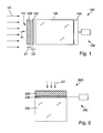
- Fig. 1 schematically a specially designed for the measurement of the dose of eyelinens dose measuring device 100 is shown according to a first embodiment.
- the dose measuring device has a radiation entrance side 110 onto which the ionizing radiation ST symbolized by arrows is incident.
- the radiation initially strikes an absorber layer 120, which has a partially absorbing effect on the ionizing radiation 110.
- the absorber layer 120 is formed in the example as part of a relatively rigid, self-supporting cover made of a plastic material.
- the absorber sheet material is a fabric equivalent material that is very similar to human tissue in its absorbing effect on penetrating ionizing radiation. It may be, for example, a plastic material or plastic material or a thin chamber filled with water.
- the absorber layer thickness D1 measured in the transmission direction R is constant over the entire utilized surface area, is 3 mm in the example case and can generally be, for example, between 2.5 mm and 3.5 mm.
- a portion of the incoming ionizing radiation is absorbed, whereby the intensity of the radiation component emerging from the exit surface is determined by the absorber layer thickness and the absorber layer material.
- a detector layer 130 which in the example is formed by a flat, planar plastic scintillator with a layer thickness between 0.01 mm and 2 mm, in particular between 50 ⁇ m and 90 ⁇ m.
- the plastic scintillator serves as a radiation detector, e.g. for photons and ß-particles.
- the detector layer or the plastic scintillator is applied directly to a light entrance side of a light guide made of Plexiglas, which in this arrangement serves as a backscatter body 140 for the radiation which has passed through the detector layer 130.
- This optical fiber physically replicates the substantial backscattering effects in the ICRU sphere.
- the scintillation light which is produced by the plastic scintillator under the influence of the incoming ionizing radiation, passes in part via the light guide 140 to the entrance side of an optoelectronic transducer 150 in the form of a photomultiplier.
- the photomultiplier is an example of an optical photon light detector. The intensity of the incident radiation is detected on the basis of the output from the photomultiplier electrical signals.
- the analog pulses of the photomultiplier are discriminated by one or more electronic thresholds. If more than one count signal is evaluated, the dose is calculated using a suitable linear combination of the individual cell rates.
- the thresholds are chosen so that there is an optimal energy dependence.
- the photomultiplier and the components connected thereto e.g., electronic components for signal shaping and amplification, data acquisition system, computer
- the layer thickness D2 of the plastic scintillator as a parameter, the ratio of the efficiency between ⁇ -particles and photon radiation can be optimized.
- the detector layer thickness D2 is in the example of a few tenths of a millimeter (eg at about 0.1 mm) to generate sufficient Szintillationslichtausbeute on the one hand and on the other hand, the depth range in which the detection takes place as precisely as possible in the range of about 3 mm from the radiation entrance surface 110th to hold the detector.
- the dose measuring device can be realized as a portable measuring device, in which the actual probe with the combination of absorber layer and subsequent detector layer on the Attached end face of a light guide, which acts as a backscatter element and at the same time directs scintillation light to the photodetector of the evaluation.
- the structure of the dose measuring device is similar, with the exception of the absorber layer 120, the structure of in the EP 2 469 304 A2 described dose measuring device for measuring the direction equivalent dose.
- the detector of the local dose measuring device comprises at the light entrance side of a plastic scintillator an opaque, flat, in particular flat cover element, which has substantially identical properties as tissue-equivalent material or tissue with a thickness of 0.07 with respect to its absorption properties for passing through the cover element to be measured radiation mm.
- the corresponding absorber layer is substantially thicker, since preferably an absorber layer thickness of approximately 3 mm is provided when tissue-equivalent material is used.
- a dose measuring device of EP 2 469 304 A2 shown type can be converted into a dose measuring device for the measurement of the eye lens dose by still another cover is applied in addition to the approximately 0.07 mm thick cover whose effect on ionizing radiation, for example, an absorber layer thickness of 2.93 mm ( ⁇ 20% ), so that the already provided, only 70 .mu.m thick cover including the further cover has substantially the same absorbing effect as an absorber layer according to the invention claimed here.
- the thin cover element described there could be replaced by a thicker absorber layer of the type described here.
- the measuring device can be designed as a multipurpose dose measuring device by providing interchangeable absorber elements (eg in the form of suitable cover elements) which, for example, for the measurement of the skin dose correspond to an absorber layer thickness of approximately 0.07 mm of a tissue-equivalent material and in the other case for the measurement of the eye lens dose, an absorber layer thickness with the effect of an approximately 3 mm (ie 2 mm to 4 mm) thick absorber layer of tissue-equivalent material.
- interchangeable absorber elements eg in the form of suitable cover elements
- a liquid scintillator of equal or similar thickness can be used to form a liquid detector instead of a solid state detector.
- the liquid scintillator material may be e.g. is water, a liquid hydrocarbon (e.g., toluene, benzene), or a similar liquid which is mixed with scintillator molecules.
- Fig. 2 shows a second embodiment of a dose measuring device 200 for measuring the dose of the eyelinens.
- an approximately 3 mm thick absorber layer 220 is applied directly to an approximately 100 ⁇ m thick detector layer 130 made of a semiconductor material. Lower thicknesses of the detector layer are possible, but possibly heavier with the required quality produced.
- the thin detector layer is applied by means of a suitable thin-film technology directly on a light entrance side of a backscatter 240 in the form of a plexiglass body with a thickness of about 5 mm to 10 mm.
- the semiconductor layer (detector layer 230) is connected to an evaluation device 290 via electrical connection lines.
- the radiation component which enters the detector layer 230 through the absorber layer 220 and those radiation components which enter the backscattering element 240 after passing through the absorber layer and the detector layer and are scattered back in the direction of the detector layer lead in the semiconductor layer to generate electrical charges Amounts of charge is proportional to the absorbed radiation dose.
- the evaluation device 290 is suitable for the quantitative evaluation of this amount of electrical charge. It may include, for example, a preamplifier, an amplifier, a discriminator or single-channel or multi-channel analyzer, a processor unit for processing the signals and similar components.
- the absorber layer could be formed by a thin film of titanium or other medium atomic number metal or a plastic film coated with a metal layer of suitable thickness.
- a third embodiment of a dose measuring device 300 for measuring the dose of the eyelinens is shown.
- a surface-extended gas-filled proportional counter or a flat ionization chamber 330 which acts as a detector layer and is inserted between an inlet-side absorber layer 320 (fabric-equivalent plastic layer with a layer thickness of about 3 mm) and an exit-side backscatter element 340.
- the arrangement with a gas-filled radiation detector has a perpendicular to the transmission direction flat extended, in the direction of radiation only about 1 mm 100 mm thick housing 332, which forms a counting gas-filled chamber.
- the chamber Within the chamber (detector chamber) run numerous parallel, electrically conductive count wires 334, which are each electrically connected to the evaluation device 390.
- the function of the arrangement with a gas-filled detector substantially corresponds to the function of known counter tubes or ionization chambers, for which reason a detailed description is omitted here.
- All embodiments have in common that they allow a direct, dose-correct measurement of the eye lens dose with high spatial and temporal resolution due to their construction and the dimensioning of the important for the radiation detection components (absorber layer, detector layer, optionally backscatter element).
- the radiation detection components aborber layer, detector layer, optionally backscatter element.
- inhomogeneous and / or larger radiation fields can be analyzed with regard to the existence of particularly radiation-stressed areas and / or largely unloaded areas.
Landscapes
- Health & Medical Sciences (AREA)
- Life Sciences & Earth Sciences (AREA)
- Molecular Biology (AREA)
- Physics & Mathematics (AREA)
- Ophthalmology & Optometry (AREA)
- Heart & Thoracic Surgery (AREA)
- Spectroscopy & Molecular Physics (AREA)
- Biophysics (AREA)
- General Physics & Mathematics (AREA)
- Engineering & Computer Science (AREA)
- Biomedical Technology (AREA)
- High Energy & Nuclear Physics (AREA)
- Medical Informatics (AREA)
- Surgery (AREA)
- Animal Behavior & Ethology (AREA)
- General Health & Medical Sciences (AREA)
- Public Health (AREA)
- Veterinary Medicine (AREA)
- Measurement Of Radiation (AREA)
Applications Claiming Priority (1)
| Application Number | Priority Date | Filing Date | Title |
|---|---|---|---|
| DE202014005506.8U DE202014005506U1 (de) | 2014-07-01 | 2014-07-01 | Dosismessgerät zur Messung der Augenlinsendosis |
Publications (1)
| Publication Number | Publication Date |
|---|---|
| EP2963451A1 true EP2963451A1 (fr) | 2016-01-06 |
Family
ID=51349915
Family Applications (1)
| Application Number | Title | Priority Date | Filing Date |
|---|---|---|---|
| EP15174475.2A Withdrawn EP2963451A1 (fr) | 2014-07-01 | 2015-06-30 | Dosimètre pour dose de lentille ophtalmique |
Country Status (2)
| Country | Link |
|---|---|
| EP (1) | EP2963451A1 (fr) |
| DE (1) | DE202014005506U1 (fr) |
Cited By (3)
| Publication number | Priority date | Publication date | Assignee | Title |
|---|---|---|---|---|
| CN109839653A (zh) * | 2017-11-29 | 2019-06-04 | 中国辐射防护研究院 | 一种个人眼晶体剂量测量装置及测量方法 |
| CN113050146A (zh) * | 2021-03-09 | 2021-06-29 | 海南核电有限公司 | 个人直读式眼晶体剂量计及其监测系统 |
| CN115524739A (zh) * | 2022-09-21 | 2022-12-27 | 中国辐射防护研究院 | β辐射个人剂量当量Hp(3)次级标准电离室及量值传递方法 |
Families Citing this family (3)
| Publication number | Priority date | Publication date | Assignee | Title |
|---|---|---|---|---|
| DE102015210059A1 (de) | 2015-06-01 | 2016-12-01 | Karlsruher Institut für Technologie | Dosismessgerät und Verfahren zur Bestimmung einer Strahlendosis |
| EP3969940A1 (fr) | 2019-05-16 | 2022-03-23 | Friedrich-Alexander-Universität Erlangen-Nürnberg | Dispositif permettant de détecter une dose de rayonnement frappant un cristallin |
| CN111239793B (zh) * | 2020-03-04 | 2024-08-06 | 北京镧宇科技有限公司 | 一种气体、固体混合探测装置及系统 |
Citations (4)
| Publication number | Priority date | Publication date | Assignee | Title |
|---|---|---|---|---|
| US3752985A (en) * | 1970-02-09 | 1973-08-14 | Com Al En Atomique | Portable detector for dosimetry of x and gamma radiation |
| GB2227633A (en) | 1989-01-26 | 1990-08-01 | Secr Defence | Radiation dosemeter |
| US20110101228A1 (en) * | 2009-10-30 | 2011-05-05 | Hamby David M | Skin Contamination Dosimeter |
| EP2469304A2 (fr) | 2010-12-21 | 2012-06-27 | Berthold Technologies GmbH & Co. KG | Détecteur de mesure de la dose équivalente directionnelle |
-
2014
- 2014-07-01 DE DE202014005506.8U patent/DE202014005506U1/de not_active Expired - Lifetime
-
2015
- 2015-06-30 EP EP15174475.2A patent/EP2963451A1/fr not_active Withdrawn
Patent Citations (4)
| Publication number | Priority date | Publication date | Assignee | Title |
|---|---|---|---|---|
| US3752985A (en) * | 1970-02-09 | 1973-08-14 | Com Al En Atomique | Portable detector for dosimetry of x and gamma radiation |
| GB2227633A (en) | 1989-01-26 | 1990-08-01 | Secr Defence | Radiation dosemeter |
| US20110101228A1 (en) * | 2009-10-30 | 2011-05-05 | Hamby David M | Skin Contamination Dosimeter |
| EP2469304A2 (fr) | 2010-12-21 | 2012-06-27 | Berthold Technologies GmbH & Co. KG | Détecteur de mesure de la dose équivalente directionnelle |
Non-Patent Citations (1)
| Title |
|---|
| MANHO CHUNG ET AL: "DEVELOPMENT OF A BETA SKIN DOSE MONITOR USING A SILICON DETECTOR", IEEE TRANSACTIONS ON NUCLEAR SCIENCE, IEEE SERVICE CENTER, NEW YORK, NY, US, vol. 38, no. 4, 1 August 1991 (1991-08-01), pages 964 - 970, XP000258526, ISSN: 0018-9499, DOI: 10.1109/23.83859 * |
Cited By (4)
| Publication number | Priority date | Publication date | Assignee | Title |
|---|---|---|---|---|
| CN109839653A (zh) * | 2017-11-29 | 2019-06-04 | 中国辐射防护研究院 | 一种个人眼晶体剂量测量装置及测量方法 |
| CN109839653B (zh) * | 2017-11-29 | 2023-06-23 | 中国辐射防护研究院 | 一种个人眼晶体剂量测量装置及测量方法 |
| CN113050146A (zh) * | 2021-03-09 | 2021-06-29 | 海南核电有限公司 | 个人直读式眼晶体剂量计及其监测系统 |
| CN115524739A (zh) * | 2022-09-21 | 2022-12-27 | 中国辐射防护研究院 | β辐射个人剂量当量Hp(3)次级标准电离室及量值传递方法 |
Also Published As
| Publication number | Publication date |
|---|---|
| DE202014005506U1 (de) | 2014-07-21 |
Similar Documents
| Publication | Publication Date | Title |
|---|---|---|
| DE102007054927B3 (de) | Ortsdosimeter zur Messung der Umgebungsäquivalentdosis von Photonenstrahlung und Verfahren zum Auslesen | |
| EP2331985B1 (fr) | Dosimètre de neutrons | |
| EP2963451A1 (fr) | Dosimètre pour dose de lentille ophtalmique | |
| EP1569012B1 (fr) | Procédé pour la détection de rayonnement ionisant | |
| DE102006006411A1 (de) | Anordnungen und Verfahren zur Bestimmung von Dosismessgrößen und zur Ermittlung von Energieinformation einfallender Strahlung aus Photonen oder geladenen Teilchen mit zählenden Detektoreinheiten | |
| EP2194362B1 (fr) | Mesure de niveau ou de densité par radiométrie | |
| DE102009018335B3 (de) | Dosimeter und Verfahren zum Ermitteln einer Energiedosis eines gepulsten Strahlungsfelds | |
| DE3219537A1 (de) | Einrichtung zur messung von dosisleistungen in streustrahlungsfeldern | |
| DE10132550B4 (de) | Verfahren zur Bestimmung der Personendosis in gemischten Neutronen-/Photonen-Feldern sowie anderer Messgrößen in anderen Strahlenfeldern | |
| DE4316083B4 (de) | Radiometrische Meßvorrichtung für Dickenmessungen | |
| EP2469304A2 (fr) | Détecteur de mesure de la dose équivalente directionnelle | |
| DE10042076A1 (de) | Neutronen-Gamma-Dosimeter und Verfahren zur Dosisbestimmung | |
| EP0995132B1 (fr) | Procédé et appareil pour la détermination de spectres photoniques | |
| DE2829960A1 (de) | Personenstrahlungsdosimeter fuer neutronenstrahlen | |
| EP4020018B1 (fr) | Dosimètre | |
| EP1131653B1 (fr) | Procede et dispositif pour mesurer la contamination radioactive d'un objet de mesure | |
| DE10126388B4 (de) | Festkörperstrahlungsdetektor | |
| DE2447817A1 (de) | Geraet zur bestimmung der aequivalentdosis von neutronen | |
| DE202019000116U1 (de) | Vorrichtung zum Prüfen von Schutzumhausungen bei geringer Strahlungsexposition | |
| EP3101447B1 (fr) | Dosimetre et procede de determination d'une dose de radiation | |
| EP3757624B1 (fr) | Procédé et dispositif de caractérisation d'un détecteur permettant de détecter le rayonnement radioactif | |
| DE102007056989B4 (de) | Vorrichtung und Verfahren zur instantanen Erfassung von Gammastrahlendosen | |
| DE102022111674A1 (de) | Vorrichtung zur Energiebestimmung und Bestimmung einer Tiefendosisverteilung von Teilchenstrahlung | |
| DD288732A7 (de) | Neutronen-personendosimeter | |
| DE1639539B1 (de) | Dosimeter zum Messen einer Neutronendosis ueber praktisch den gesamten Neutronenenergiebereich |
Legal Events
| Date | Code | Title | Description |
|---|---|---|---|
| PUAI | Public reference made under article 153(3) epc to a published international application that has entered the european phase |
Free format text: ORIGINAL CODE: 0009012 |
|
| AK | Designated contracting states |
Kind code of ref document: A1 Designated state(s): AL AT BE BG CH CY CZ DE DK EE ES FI FR GB GR HR HU IE IS IT LI LT LU LV MC MK MT NL NO PL PT RO RS SE SI SK SM TR |
|
| AX | Request for extension of the european patent |
Extension state: BA ME |
|
| STAA | Information on the status of an ep patent application or granted ep patent |
Free format text: STATUS: THE APPLICATION IS DEEMED TO BE WITHDRAWN |
|
| 18D | Application deemed to be withdrawn |
Effective date: 20160707 |