EP2963751A1 - Disjoncteur pour courant continu et procédé de mise en uvre associé - Google Patents
Disjoncteur pour courant continu et procédé de mise en uvre associé Download PDFInfo
- Publication number
- EP2963751A1 EP2963751A1 EP13876671.2A EP13876671A EP2963751A1 EP 2963751 A1 EP2963751 A1 EP 2963751A1 EP 13876671 A EP13876671 A EP 13876671A EP 2963751 A1 EP2963751 A1 EP 2963751A1
- Authority
- EP
- European Patent Office
- Prior art keywords
- current
- circuit
- commutation
- unit
- converter
- Prior art date
- Legal status (The legal status is an assumption and is not a legal conclusion. Google has not performed a legal analysis and makes no representation as to the accuracy of the status listed.)
- Granted
Links
Images


Classifications
-
- H—ELECTRICITY
- H02—GENERATION; CONVERSION OR DISTRIBUTION OF ELECTRIC POWER
- H02H—EMERGENCY PROTECTIVE CIRCUIT ARRANGEMENTS
- H02H3/00—Emergency protective circuit arrangements for automatic disconnection directly responsive to an undesired change from normal electric working condition with or without subsequent reconnection ; integrated protection
- H02H3/38—Emergency protective circuit arrangements for automatic disconnection directly responsive to an undesired change from normal electric working condition with or without subsequent reconnection ; integrated protection responsive to both voltage and current; responsive to phase angle between voltage and current
-
- H—ELECTRICITY
- H01—ELECTRIC ELEMENTS
- H01H—ELECTRIC SWITCHES; RELAYS; SELECTORS; EMERGENCY PROTECTIVE DEVICES
- H01H33/00—High-tension or heavy-current switches with arc-extinguishing or arc-preventing means
- H01H33/02—Details
- H01H33/59—Circuit arrangements not adapted to a particular application of the switch and not otherwise provided for, e.g. for ensuring operation of the switch at a predetermined point in the AC cycle
- H01H33/596—Circuit arrangements not adapted to a particular application of the switch and not otherwise provided for, e.g. for ensuring operation of the switch at a predetermined point in the AC cycle for interrupting DC
-
- H—ELECTRICITY
- H02—GENERATION; CONVERSION OR DISTRIBUTION OF ELECTRIC POWER
- H02H—EMERGENCY PROTECTIVE CIRCUIT ARRANGEMENTS
- H02H9/00—Emergency protective circuit arrangements for limiting excess current or voltage without disconnection
- H02H9/02—Emergency protective circuit arrangements for limiting excess current or voltage without disconnection responsive to excess current
-
- H—ELECTRICITY
- H01—ELECTRIC ELEMENTS
- H01H—ELECTRIC SWITCHES; RELAYS; SELECTORS; EMERGENCY PROTECTIVE DEVICES
- H01H83/00—Protective switches, e.g. circuit-breaking switches, or protective relays operated by abnormal electrical conditions otherwise than solely by excess current
- H01H83/20—Protective switches, e.g. circuit-breaking switches, or protective relays operated by abnormal electrical conditions otherwise than solely by excess current operated by excess current as well as by some other abnormal electrical condition
-
- H—ELECTRICITY
- H01—ELECTRIC ELEMENTS
- H01H—ELECTRIC SWITCHES; RELAYS; SELECTORS; EMERGENCY PROTECTIVE DEVICES
- H01H9/00—Details of switching devices, not covered by groups H01H1/00 - H01H7/00
- H01H9/54—Circuit arrangements not adapted to a particular application of the switching device and for which no provision exists elsewhere
- H01H9/541—Contacts shunted by semiconductor devices
- H01H9/542—Contacts shunted by static switch means
-
- H—ELECTRICITY
- H02—GENERATION; CONVERSION OR DISTRIBUTION OF ELECTRIC POWER
- H02H—EMERGENCY PROTECTIVE CIRCUIT ARRANGEMENTS
- H02H3/00—Emergency protective circuit arrangements for automatic disconnection directly responsive to an undesired change from normal electric working condition with or without subsequent reconnection ; integrated protection
- H02H3/08—Emergency protective circuit arrangements for automatic disconnection directly responsive to an undesired change from normal electric working condition with or without subsequent reconnection ; integrated protection responsive to excess current
-
- H—ELECTRICITY
- H02—GENERATION; CONVERSION OR DISTRIBUTION OF ELECTRIC POWER
- H02H—EMERGENCY PROTECTIVE CIRCUIT ARRANGEMENTS
- H02H7/00—Emergency protective circuit arrangements specially adapted for specific types of electric machines or apparatus or for sectionalised protection of cable or line systems, and effecting automatic switching in the event of an undesired change from normal working conditions
- H02H7/26—Sectionalised protection of cable or line systems, e.g. for disconnecting a section on which a short-circuit, earth fault, or arc discharge has occured
- H02H7/268—Sectionalised protection of cable or line systems, e.g. for disconnecting a section on which a short-circuit, earth fault, or arc discharge has occured for DC systems
-
- H—ELECTRICITY
- H02—GENERATION; CONVERSION OR DISTRIBUTION OF ELECTRIC POWER
- H02J—ELECTRIC POWER NETWORKS; CIRCUIT ARRANGEMENTS OR SYSTEMS FOR SUPPLYING OR DISTRIBUTING ELECTRIC POWER; SYSTEMS FOR STORING ELECTRIC ENERGY
- H02J1/00—Circuit arrangements for DC mains or DC distribution networks
Definitions
- the invention relates to a power electronic technology, more particularly, to a direct current circuit breaker and its implementation process.
- the quick direct current circuit breaker becomes the key device to ensure the system running security, stability and reliability.
- the alternating current has two natural zero-crossing points in a period, the alternating current circuit breaker just uses the current natural zero-crossing point to cut off the current, meanwhile the direct current has no natural zero-crossing point, therefor, the cut off of the direct current is far more different than the cut off of the alternating current.
- the present invention provides a direct current circuit breaker and its implementation process, which realizes the effect of cutting out the direct current by turn-off power electronic devices, it has no arc cutting and fast speed.
- said cutout unit and commutation unit all include the half/full bridge structure converter;
- the number of converters in the cutout unit is greater than it in the commutation unit, said commutation unit has a smaller on-resistance compared to said cutout unit.
- said full bridge structure converter includes the capacitor and H bridge structure power semiconductor switch module;
- Said H bridge structure power semiconductor switch module includes four power semiconductor switch modules; Wherein each two in series together and constitute a branch, two branches parallel, and extract the intermediate point of the two branches as the input or output end;
- the number of said capacitor is at least one, and it connects with the power semiconductor switch module branch after a series.
- said H bridge structure power semiconductor switch module includes four diodes and at least one power semiconductor switch; Wherein each two diodes are in series to consist a branch, two branches parallel, and the intermediate point of the two branches is extracted as the input end and output end; Wherein the power semiconductor switch is in parallel with the capacitor and in parallel with said branch made up by the diodes.
- said half bridge structure converter includes two power semiconductor switch modules and at least one capacitor; Said two power semiconductor switch modules, after in series together, are in parallel with the capacitor; The intermediate point between one end of the capacitor and power semiconductor switch module connected in series is as the input or output end.
- said power semiconductor switch module includes power semiconductor switch parallel opposite and fly back diode.
- said energy absorption circuit includes lightning arrester and slide rheostat.
- a limit current device consists of said direct current breaker, of which the improvement is that it comprises at least said two current breakers connected in series, a branch in series made by said direct current breaker is connected with a current path of transmission or distribution line.
- Said current limiting device suits for handling a certain number of said direct current circuit breaker when the current beyond the current limit in the current path so that it makes the current of said mechanical switch and commutation unit of said at least two direct current circuit breakers reverse to the energy absorption circuit.
- the specific number is determined by the current limit level, in general, the principle to select the number is: making the current drop to or below the current limit and keeping in the reservation current value at least at a certain time period.
- a limit current device comprises at least one set parallel interrupt unit and energy absorption circuit, and mechanical switch and cutout unit in series; Each set parallel interrupt unit and the energy absorption circuit is in series;
- An application method of the direct current circuit breaker improved is that, said method includes the following steps:
- control circuit sends the signal to turn off the converter of said commutation unit
- the extreme value of the first current is greater than or equal to the rated current of the circuit connect to the convertor station.
- step C turn off said mechanical switch after the first period time form locking said commutation unit.
- step C controls circuit judge current when the current switches to cutout circuit form commutation circuit, the control circuit turns off said mechanical switch.
- the application method used for the first current limiting device is that, when said current in the current path exceeds the limit determined by the applied line, the first specific number of said at least two devices is handled, and the corresponding cutout unit converter form this is locked to make the current reverse to said corresponding energy absorption circuit.
- the application method for using the second current limiting device is that, when the current exceeds the current limit in said current path, the commutation unit converter is locked, the mechanical switch is cut off, and then the first specific number said cutout unit converters is locked, thus to make the current reverse , through said high speed mechanical switch and said commutation unit converter, to the first specific number cutout unit converters, and then converse to the corresponding energy absorption circuit.
- a breaker is illustrated by the present embodiment, its electrical structure shown as figure 1 , including the cutout circuit, the commutation circuit and the energy absorption circuit connected in parallel.
- the commutation circuit is used for switching the external current into cutout circuit, including commutation inductance, commutation unit and mechanical switch connected in series, turn-on the bidirectional current;
- the commutation unit only enduring the on-state voltage drop when the cutout switch turns on;
- the high speed switch cuts off, it endures the voltage of the whole breaker.
- the number of the mechanical switch is at least one, so that it can endure the higher voltage.
- the cutout circuit is in charge of quickly cutting off the direct current in the path after the high speed switch cutting off, the cut-off, it can cut off the bidirectional current, wherein including cutout inductance and cutout unit connected in series.
- the commutation inductance in the commutation circuit and the cutout inductance in the cutout circuit used are the normal inductance, such as air-core inductance with dozens of microhenries.
- the full or half bridge structure converter is included, but number of the cutout unit is greater than it of the commutation unit, so that commutation unit has a smaller on-resistance compared to cutout unit.
- the full bridge structure converter includes H bridge structure power semiconductor switch module and the capacitor, as shown in figure 2 ,number of the capacitor is at least one, and it connects with the power semiconductor switch module branch after a series, wherein:
- Half bridge structure converter includes the capacitor and two power semiconductor module, as shown in figure 4 ; Said two power semiconductor module after in series are in parallel with the capacitor, and extract the intermediate point between one end of the capacitor and the power semiconductor module as the input end and output end.
- Two half bridge structure converters, commutation inductance and mechanical switch are in series and constitute the commutation circuit.
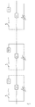
- the breaker realized by the half bridge structure converter is shown as figure 7 .
- the power semiconductor switch module in the present embodiment includes IGBT and diode parallel opposite.
- the energy absorption circuit after cutting off the circuit and the direct current can absorb the energy stored by the inductance of the HVDC system, including lightning arrester and slide rheostat. While realizing by the slide rheostat, where the voltage in the system is higher, the value of resistance of the slide rheostat is less, where the voltage in the system is smaller, the value of resistance of the slide rheostat is larger.
- control circuit shown as figure 8 .
- the control circuit controls the turning-on and cutting off of the commutation circuit, the cutout circuit and the mechanical switch, being used to for controlling the circuit bring in and quite. It could include the processor, DSP or FPGA and others.
- the turn off signal of the commutation unit converter is still received or received again, firstly the commutation unit converter is turned off, after that, turn off the high speed mechanical switch is turned off, and after that since receiving the turn off signal of said cutout unit converter, and then the cutout unit converter is turned off.
- the first specific number of said at least two devices is handled, to make the corresponding cutout unit converter form this lock, and can make the current reverse to said corresponding energy absorption circuit, shown as figure 9 .
- the commutation unit converter is locked, the high speed mechanical switch is cut off, and then the first specific number said cutout unit converters is locked, thus to make the current through said high speed mechanical switch and said commutation unit converter reverse to the first specific number cutout unit converters, and then to make it converse to the corresponding energy absorption circuit, shown as figure 10 .
- said first specific number is determined.
- the first current limiting arrangement proposed by the present embodiment is shown as figure 9 , that it is in series multiple direct current breaker. Said current limiting arrangement is suit for handling a certain number of said direct current circuit breaker when the current beyond the current limit in the current path, and it make the current of said mechanical switch and commutation unit of said at least two direct current circuit breakers reverse to the energy absorption circuit.
- the second current limiting arrangement proposed by the present embodiment is shown as figure 10 , correspondingly its structure is changed, including at least one set parallel commutation unit and energy absorption circuit, and mechanical switch and cutout unit in series; each set parallel commutation unit is in series energy absorption circuit;
- said mechanical switch, said commutation unit and the parallel cutout unit and energy absorption circuit are handled to make the current flowed through the mechanical switch and the commutation unit reverse to the cutout unit and the energy absorption circuit in series.
- the embodiment uses power semiconductor switch module to realize the function of commutation and cutout, achieve the effect of cost savings.
Landscapes
- Engineering & Computer Science (AREA)
- Power Engineering (AREA)
- Driving Mechanisms And Operating Circuits Of Arc-Extinguishing High-Tension Switches (AREA)
- Inverter Devices (AREA)
- Emergency Protection Circuit Devices (AREA)
Applications Claiming Priority (2)
| Application Number | Priority Date | Filing Date | Title |
|---|---|---|---|
| CN201310061175.9A CN103280763B (zh) | 2013-02-27 | 2013-02-27 | 一种直流断路器及其实现方法 |
| PCT/CN2013/088423 WO2014131298A1 (fr) | 2013-02-27 | 2013-12-03 | Disjoncteur pour courant continu et procédé de mise en œuvre associé |
Publications (3)
| Publication Number | Publication Date |
|---|---|
| EP2963751A1 true EP2963751A1 (fr) | 2016-01-06 |
| EP2963751A4 EP2963751A4 (fr) | 2016-11-02 |
| EP2963751B1 EP2963751B1 (fr) | 2019-04-03 |
Family
ID=49063239
Family Applications (1)
| Application Number | Title | Priority Date | Filing Date |
|---|---|---|---|
| EP13876671.2A Active EP2963751B1 (fr) | 2013-02-27 | 2013-12-03 | Disjoncteur pour courant continu et procédé de mise en uvre associé |
Country Status (4)
| Country | Link |
|---|---|
| US (1) | US10707674B2 (fr) |
| EP (1) | EP2963751B1 (fr) |
| CN (1) | CN103280763B (fr) |
| WO (1) | WO2014131298A1 (fr) |
Cited By (6)
| Publication number | Priority date | Publication date | Assignee | Title |
|---|---|---|---|---|
| EP3349233A1 (fr) * | 2017-01-13 | 2018-07-18 | Siemens Aktiengesellschaft | Unité de commutation de puissance en courant continu |
| IT201700021274A1 (it) * | 2017-02-24 | 2018-08-24 | Ricerca Sul Sist Energetico Rse S P A | Interruttore ibrido per corrente continua |
| EP3240004A4 (fr) * | 2014-12-26 | 2018-09-05 | Tokyo Institute of Technology | Disjoncteur |
| CN111786366A (zh) * | 2020-06-18 | 2020-10-16 | 许昌许继软件技术有限公司 | 一种多极结构的直流开关设备 |
| EP3879548A1 (fr) * | 2020-03-10 | 2021-09-15 | ABB Schweiz AG | Disjoncteur de limiteur de courant de défaut |
| CN117529861A (zh) * | 2021-06-28 | 2024-02-06 | 华为数字能源技术有限公司 | 一种断路器及供电系统 |
Families Citing this family (80)
| Publication number | Priority date | Publication date | Assignee | Title |
|---|---|---|---|---|
| CN103280763B (zh) | 2013-02-27 | 2016-12-28 | 国网智能电网研究院 | 一种直流断路器及其实现方法 |
| CN103633631B (zh) * | 2013-10-16 | 2016-09-28 | 国家电网公司 | 一种高压超导限流直流断路器的开断方法 |
| CN103532091B (zh) * | 2013-10-16 | 2016-01-20 | 国家电网公司 | 一种机电一体化高压直流断路器的开断方法 |
| WO2015090464A1 (fr) * | 2013-12-20 | 2015-06-25 | Siemens Aktiengesellschaft | Dispositif et procédé pour commuter un courant continu |
| CN104767170B (zh) * | 2014-01-06 | 2018-12-11 | 国家电网公司 | 一种混合式高压直流断路器及其实现方法 |
| CN104767171B (zh) * | 2014-01-06 | 2018-01-19 | 国家电网公司 | 一种高压直流断路器及其实现方法 |
| CN103762547A (zh) * | 2014-01-08 | 2014-04-30 | 西安交通大学 | 基于人工过零的模块式高压真空直流开断装置 |
| CN104979795B (zh) * | 2014-04-08 | 2018-10-09 | 国家电网公司 | 一种无源型高压直流断路器及其实现方法 |
| CN104009450B (zh) * | 2014-05-07 | 2017-08-25 | 华南理工大学 | 模块组合高压直流断路器 |
| CN103986122B (zh) * | 2014-05-14 | 2017-05-10 | 国家电网公司 | 一种附加二极管的模块化限流断路器功率模块 |
| JP6749319B2 (ja) * | 2014-06-30 | 2020-09-02 | サイブレーク アーベーScibreak Ab | 電流を遮断する装置、システム及び方法 |
| US9343897B2 (en) | 2014-07-07 | 2016-05-17 | General Electric Company | Circuit breaker system and method |
| CN104242265B (zh) * | 2014-08-29 | 2018-02-13 | 梦网荣信科技集团股份有限公司 | 一种直流配电网全固态直流断路器 |
| CN104702256A (zh) * | 2014-12-29 | 2015-06-10 | 国家电网公司 | 一种高压直流断路器的igbt驱动方法 |
| CN104635151B (zh) * | 2014-12-29 | 2018-07-20 | 国家电网公司 | 一种级联全桥直流断路器低压等效试验电路及其检测方法 |
| CN104638619B (zh) * | 2014-12-29 | 2018-11-27 | 国家电网公司 | 一种级联全桥直流断路器控制系统的控制方法 |
| CN105807216A (zh) * | 2014-12-29 | 2016-07-27 | 国家电网公司 | 一种高压直流断路器全桥模块的试验装置及其试验方法 |
| EP3051643B1 (fr) * | 2015-01-30 | 2017-09-06 | General Electric Technology GmbH | Disjoncteur à courant continu avec compteur de génération de courant |
| CN104637751B (zh) * | 2015-02-06 | 2018-05-22 | 孙毅彪 | 无电弧型串联智能桥强控式高压断路器 |
| CN104637752B (zh) * | 2015-02-06 | 2018-04-06 | 孙毅彪 | 无电弧型并联智能桥强控式高压断路器 |
| CN104901269B (zh) * | 2015-06-02 | 2018-05-01 | 梦网荣信科技集团股份有限公司 | 一种全固态直流断路器及其控制方法 |
| CN104980137B (zh) * | 2015-06-10 | 2018-05-04 | 许继电气股份有限公司 | 一种强迫换流型全固态高速直流断路器和换流开关 |
| GB2541465A (en) * | 2015-08-21 | 2017-02-22 | General Electric Technology Gmbh | Electrical assembly |
| CN106558865B (zh) * | 2015-09-25 | 2019-03-15 | 全球能源互联网研究院 | 一种改进型级联全桥高压直流断路器及其快速重合方法 |
| CN105262068A (zh) * | 2015-10-14 | 2016-01-20 | 南京南瑞继保电气有限公司 | 一种高压直流断路器及其控制方法 |
| CN105356411B (zh) * | 2015-11-10 | 2018-03-13 | 南京南瑞继保电气有限公司 | 一种桥式电路、高压直流断路器及其控制方法 |
| CN105305371B (zh) * | 2015-11-14 | 2018-05-25 | 华中科技大学 | 一种带耦合电抗器的高压直流断路器 |
| FR3043833B1 (fr) * | 2015-11-17 | 2017-12-22 | Inst Supergrid | Disjoncteur pour un reseau a courant continu haute tension, avec oscillation forcee de courant |
| CN105281286A (zh) * | 2015-11-18 | 2016-01-27 | 广州供电局有限公司 | 限流型开断装置 |
| SE539392C2 (en) * | 2015-12-28 | 2017-09-12 | Scibreak Ab | Arrangement, system, and method of interrupting current |
| CN105429121A (zh) * | 2015-12-28 | 2016-03-23 | 大连理工大学 | 混合开关式故障限流模块以及装置 |
| CN105743114B (zh) * | 2016-02-29 | 2023-11-07 | 全球能源互联网研究院 | 直流输电系统抵御受端故障的直流能量吸收装置及方法 |
| CN105655966A (zh) * | 2016-03-15 | 2016-06-08 | 许继电气股份有限公司 | 一种直流断路器 |
| CN105680411B (zh) * | 2016-03-29 | 2018-04-06 | 中国人民解放军海军工程大学 | 直流固态断路器及断路控制方法 |
| CN105680409B (zh) * | 2016-04-19 | 2018-03-30 | 南京南瑞继保电气有限公司 | 一种桥式电路、直流电流分断装置及其控制方法 |
| CN105790236B (zh) * | 2016-04-19 | 2018-03-13 | 南京南瑞继保电气有限公司 | 一种直流电流关断装置及其控制方法 |
| CN105896492B (zh) * | 2016-06-16 | 2019-02-15 | 南方电网科学研究院有限责任公司 | 一种混合式直流断路器 |
| CN107645154B (zh) * | 2016-07-20 | 2020-03-06 | 全球能源互联网研究院有限公司 | 一种新型组合式直流断路器及其应用方法 |
| CN106207991A (zh) * | 2016-07-27 | 2016-12-07 | 西安交通大学 | 一种双向高压直流混合式断路器 |
| CN106209039A (zh) * | 2016-08-18 | 2016-12-07 | 平高集团有限公司 | 一种新型混合型直流断路器及功率单元 |
| CN106329496B (zh) * | 2016-08-31 | 2018-10-19 | 许继电气股份有限公司 | 快速熔断装置及控制方法、直流断路器及控制方法 |
| CN106300296B (zh) * | 2016-09-08 | 2019-01-25 | 华北电力大学 | 一种主动短路式高压直流断路器 |
| CN106786403B (zh) * | 2016-11-22 | 2020-01-10 | 华北电力大学 | 一种带续流回路的直流固态断路器 |
| CN106532661B (zh) * | 2016-11-22 | 2019-08-06 | 平高集团有限公司 | 一种高压直流断路器的分闸控制方法 |
| CN106533145B (zh) * | 2016-11-22 | 2019-10-15 | 平高集团有限公司 | 一种高压直流断路器 |
| CN106786349A (zh) * | 2016-11-22 | 2017-05-31 | 平高集团有限公司 | 一种辅助换流模块及高压直流断路器 |
| CN107086555B (zh) * | 2017-05-31 | 2019-02-22 | 天津大学 | 一种具有自适应限流能力的直流固态断路器控制方法 |
| CN111033923B (zh) * | 2017-08-15 | 2022-10-25 | 东芝能源系统株式会社 | 直流电流切断装置 |
| CN108011389A (zh) * | 2017-11-22 | 2018-05-08 | 全球能源互联网研究院有限公司 | 一种复合型直流输电设备 |
| CN107946133B (zh) * | 2017-12-06 | 2020-01-21 | 上海电气集团股份有限公司 | 一种快速分闸机构及混合式交流断路器 |
| CN108365602B (zh) * | 2018-01-15 | 2021-01-19 | 清华大学 | 柔性直流电网限流装置的控制方法和系统 |
| CN110854797B (zh) * | 2018-08-21 | 2022-01-28 | 西安西电高压开关有限责任公司 | 直流断路器及其中央控制器、控制方法 |
| CN109245030B (zh) * | 2018-09-30 | 2020-04-28 | 许继电气股份有限公司 | 直流断路器全桥子模块的电容容值确定方法及系统 |
| CN113196074B (zh) * | 2018-11-13 | 2025-04-25 | 伊利诺伊理工学院 | 采用瞬态换向电流注入电路的混合式断路器 |
| CN111211541B (zh) * | 2018-11-21 | 2022-06-10 | 中国船舶重工集团公司第七一一研究所 | 直流固态断路器 |
| CN109742724A (zh) * | 2018-12-19 | 2019-05-10 | 武汉船用电力推进装置研究所(中国船舶重工集团公司第七一二研究所) | 一种半桥式混合型高压直流断路器拓扑电路 |
| CN113574623B (zh) * | 2019-03-29 | 2024-06-25 | 西门子股份公司 | 混合断路器、混合断路系统及断路方法 |
| CN110098593A (zh) * | 2019-04-24 | 2019-08-06 | 上海电力学院 | 具有投入电流方向选择的电流注入式机械高压直流断路器 |
| CN110768203B (zh) * | 2019-11-22 | 2024-04-26 | 西北农林科技大学 | 一种基于软开关技术的无弧直流断路器拓扑及其实现方法 |
| DE102019218893B4 (de) * | 2019-12-04 | 2021-12-30 | Volkswagen Aktiengesellschaft | Hochsetzsteller und Verfahren zum Betreiben eines Hochsetzstellers |
| CN112952744B (zh) * | 2019-12-11 | 2022-09-20 | 清华四川能源互联网研究院 | 直流断路器、直流开断方法及电力系统 |
| CN112003590A (zh) * | 2020-07-04 | 2020-11-27 | 电子科技大学 | 一种用于井间电磁的大功率正弦信号产生电路及产生方法 |
| US11973339B2 (en) * | 2020-08-10 | 2024-04-30 | Ohio State Innovation Foundation | Modular DC circuit breaker with integrated energy storage for future DC networks |
| CN112054495A (zh) * | 2020-08-14 | 2020-12-08 | 中电普瑞电力工程有限公司 | 一种用于直流系统的能量吸收电路及其控制方法 |
| US11509128B2 (en) | 2020-09-14 | 2022-11-22 | Abb Schweiz Ag | Multi-port solid-state circuit breaker apparatuses, systems, and methods |
| CN112615611A (zh) * | 2020-12-22 | 2021-04-06 | 广东电网有限责任公司 | 一种多端口直流断路器及多端口直流系统 |
| CN113437731B (zh) * | 2021-07-14 | 2023-03-14 | 东北林业大学 | 一种基于高速机械开关的限流型混合直流断路器 |
| CN113839370B (zh) * | 2021-09-02 | 2025-08-26 | 全球能源互联网研究院有限公司 | 一种电压调控式振荡型直流断路器及其控制方法 |
| CN114172129B (zh) * | 2021-12-02 | 2022-06-24 | 中国科学院电工研究所 | 可双向开断和软起动的混合器件固态断路器及控制方法 |
| CN114172132A (zh) * | 2021-12-07 | 2022-03-11 | 广东电网有限责任公司 | 一种双向限流的直流限流器 |
| CN114498581B (zh) * | 2022-01-10 | 2024-12-31 | 国网冀北电力有限公司电力科学研究院 | 电流注入型直流断路器及电流注入方法 |
| CN114421420B (zh) * | 2022-02-10 | 2023-05-30 | 华北电力大学(保定) | 适用于柔直配电网的阻感型限流式多端口直流断路器 |
| CN114845499B (zh) * | 2022-05-13 | 2024-02-06 | 富芯微电子有限公司 | 一种功率半导体模块 |
| CN118920413B (zh) * | 2023-05-08 | 2025-12-09 | 南京南瑞继保电气有限公司 | 无源型电流开断装置、电流开断模块及电流开断控制方法 |
| CN116995630B (zh) * | 2023-07-13 | 2024-08-23 | 国家电网有限公司直流技术中心 | J-d串联混合型直流故障限流器、控制及参数设计方法 |
| FR3154539B1 (fr) * | 2023-10-20 | 2026-02-20 | Inst Supergrid | Dispositif de coupure pour courant électrique sous haute tension continue à commande sécurisée |
| CN117748426B (zh) * | 2023-11-24 | 2025-06-27 | 国网河南省电力公司电力科学研究院 | 基于在线监测的高可靠igct换流阀可熔断mov保护装置 |
| CN118117552B (zh) * | 2024-03-01 | 2024-09-13 | 湖南工业大学 | 碳化硅固态断路器零电流软关断跳闸拓扑及其控制方法 |
| CN118198987B (zh) * | 2024-05-20 | 2024-08-06 | 四川大学 | 一种耗能型直流断路器及其控制方法 |
| CN119181625B (zh) * | 2024-09-29 | 2025-10-10 | 西安交通大学 | 一种低压混合式直流断路器尾部电流可靠换流方法及系统 |
Family Cites Families (16)
| Publication number | Priority date | Publication date | Assignee | Title |
|---|---|---|---|---|
| US3641358A (en) * | 1970-06-10 | 1972-02-08 | Hughes Aircraft Co | Consecutive crowbar circuit breaker |
| US4740858A (en) * | 1985-08-06 | 1988-04-26 | Mitsubishi Denki Kabushiki Kaisha | Zero-current arc-suppression dc circuit breaker |
| JPH08315666A (ja) * | 1995-05-12 | 1996-11-29 | Mitsubishi Electric Corp | 遮断器および遮断装置 |
| US6075684A (en) * | 1998-03-23 | 2000-06-13 | Electric Boat Corporation | Method and arrangement for direct current circuit interruption |
| DE19953551C1 (de) * | 1999-11-08 | 2001-08-16 | Abb Hochspannungstechnik Ag Zu | Schneller strombegrenzender Schalter |
| JP2005019106A (ja) * | 2003-06-24 | 2005-01-20 | Sumitomo Electric Ind Ltd | 直流リレー |
| EP1538645B1 (fr) * | 2003-12-05 | 2006-03-01 | Société Technique pour l'Energie Atomique TECHNICATOME | Dispositif disjoncteur hybride |
| WO2010060476A1 (fr) * | 2008-11-26 | 2010-06-03 | Abb Technology Ag | Ensemble disjoncteur pour courant continu haute tension et procédé associé |
| WO2011057675A1 (fr) * | 2009-11-16 | 2011-05-19 | Abb Technology Ag | Dispositif et procédé d'interruption du courant d'une ligne de transport ou de distribution d'électricité et dispositif de limitation de courant |
| CN201877823U (zh) * | 2010-11-24 | 2011-06-22 | 上海思源电力电容器有限公司 | 直流断路器用电容器 |
| CN102222874B (zh) * | 2011-06-10 | 2014-04-09 | 南京航空航天大学 | 一种直流固态断路器 |
| CN102290279A (zh) * | 2011-06-30 | 2011-12-21 | 中国人民解放军海军工程大学 | 高速真空直流限流断路器 |
| CN202276128U (zh) * | 2011-09-15 | 2012-06-13 | 苏州微体电子科技有限公司 | 一种谐振型直流固态断路器 |
| CA2860171C (fr) * | 2011-12-22 | 2021-09-21 | Siemens Aktiengesellschaft | Dispositif disjoncteur de circuit cc hybride |
| FR2985082B1 (fr) * | 2011-12-23 | 2014-02-21 | Alstom Technology Ltd | Dispositif disjoncteur mecatronique et procede de declenchement associe et application a la coupure de courant continu eleve |
| CN103280763B (zh) | 2013-02-27 | 2016-12-28 | 国网智能电网研究院 | 一种直流断路器及其实现方法 |
-
2013
- 2013-02-27 CN CN201310061175.9A patent/CN103280763B/zh active Active
- 2013-12-03 US US14/771,105 patent/US10707674B2/en active Active
- 2013-12-03 WO PCT/CN2013/088423 patent/WO2014131298A1/fr not_active Ceased
- 2013-12-03 EP EP13876671.2A patent/EP2963751B1/fr active Active
Cited By (9)
| Publication number | Priority date | Publication date | Assignee | Title |
|---|---|---|---|---|
| EP3240004A4 (fr) * | 2014-12-26 | 2018-09-05 | Tokyo Institute of Technology | Disjoncteur |
| EP3349233A1 (fr) * | 2017-01-13 | 2018-07-18 | Siemens Aktiengesellschaft | Unité de commutation de puissance en courant continu |
| IT201700021274A1 (it) * | 2017-02-24 | 2018-08-24 | Ricerca Sul Sist Energetico Rse S P A | Interruttore ibrido per corrente continua |
| EP3879548A1 (fr) * | 2020-03-10 | 2021-09-15 | ABB Schweiz AG | Disjoncteur de limiteur de courant de défaut |
| WO2021180397A1 (fr) * | 2020-03-10 | 2021-09-16 | Abb Schweiz Ag | Disjoncteur limiteur de courant de défaut |
| US11757276B2 (en) | 2020-03-10 | 2023-09-12 | Abb Schweiz Ag | Fault current limiter circuit breaker |
| CN111786366A (zh) * | 2020-06-18 | 2020-10-16 | 许昌许继软件技术有限公司 | 一种多极结构的直流开关设备 |
| CN117529861A (zh) * | 2021-06-28 | 2024-02-06 | 华为数字能源技术有限公司 | 一种断路器及供电系统 |
| EP4340149A4 (fr) * | 2021-06-28 | 2024-08-28 | Huawei Digital Power Technologies Co., Ltd. | Disjoncteur et système d'alimentation électrique |
Also Published As
| Publication number | Publication date |
|---|---|
| CN103280763A (zh) | 2013-09-04 |
| WO2014131298A1 (fr) | 2014-09-04 |
| CN103280763B (zh) | 2016-12-28 |
| EP2963751B1 (fr) | 2019-04-03 |
| US10707674B2 (en) | 2020-07-07 |
| US20160006236A1 (en) | 2016-01-07 |
| EP2963751A4 (fr) | 2016-11-02 |
Similar Documents
| Publication | Publication Date | Title |
|---|---|---|
| EP2963751B1 (fr) | Disjoncteur pour courant continu et procédé de mise en uvre associé | |
| US10811864B2 (en) | DC circuit breaker with counter current generation | |
| CN103178486B (zh) | 一种直流断路器及其开断方法 | |
| Wang et al. | Future HVDC-grids employing modular multilevel converters and hybrid DC-breakers | |
| KR101720112B1 (ko) | 선로 전류를 차단 또는 제한하는 장치 및 그의 제어 방법 | |
| EP2768102B1 (fr) | Dispositif d'interruption de circuit | |
| US9478974B2 (en) | DC voltage circuit breaker | |
| CN102522882B (zh) | 一种换流器功率组件的保护电路 | |
| CN101971474A (zh) | 具有保护电路的磁能再生开关 | |
| CN106206208A (zh) | 大功率双向开断的混合式直流断路器 | |
| CN103441489B (zh) | 一种多端直流系统用直流断路器及其控制方法 | |
| CN105680411B (zh) | 直流固态断路器及断路控制方法 | |
| CN105281288A (zh) | 一种具备双向阻断功能的直流断路器拓扑 | |
| US20190074149A1 (en) | DC Voltage Switch | |
| US10218170B2 (en) | Current-limiting device utilizing a superconductor for a current-limiting operation | |
| CN105281287B (zh) | 一种基于晶闸管的具备双向阻断功能的直流断路器拓扑 | |
| CN203166459U (zh) | 一种直流断路器 | |
| Bhatta et al. | A new design of Z-source capacitors to ensure SCR's turn-off for the practical applications of ZCBs in realistic DC network protection | |
| Sander et al. | A novel current-injection based design for HVDC circuit breakers | |
| CN105811379A (zh) | 一种有源混合式高压直流断路器用供电电路和供电方法 | |
| CN207559539U (zh) | 直流断路器和电路保护装置 | |
| CN105991055A (zh) | 具有冗余运行能力的ac/dc换流器子模块及换流器 | |
| CN201639282U (zh) | 一种短路故障限流器 | |
| CN102684230A (zh) | 适用于高压大容量交直流输配电系统的复合型全控固态开关 |
Legal Events
| Date | Code | Title | Description |
|---|---|---|---|
| PUAI | Public reference made under article 153(3) epc to a published international application that has entered the european phase |
Free format text: ORIGINAL CODE: 0009012 |
|
| 17P | Request for examination filed |
Effective date: 20150925 |
|
| AK | Designated contracting states |
Kind code of ref document: A1 Designated state(s): AL AT BE BG CH CY CZ DE DK EE ES FI FR GB GR HR HU IE IS IT LI LT LU LV MC MK MT NL NO PL PT RO RS SE SI SK SM TR |
|
| AX | Request for extension of the european patent |
Extension state: BA ME |
|
| DAX | Request for extension of the european patent (deleted) | ||
| REG | Reference to a national code |
Ref country code: DE Ref legal event code: R079 Ref document number: 602013053486 Country of ref document: DE Free format text: PREVIOUS MAIN CLASS: H02H0003080000 Ipc: H01H0033590000 |
|
| A4 | Supplementary search report drawn up and despatched |
Effective date: 20161006 |
|
| RIC1 | Information provided on ipc code assigned before grant |
Ipc: H01H 33/59 20060101AFI20160929BHEP |
|
| STAA | Information on the status of an ep patent application or granted ep patent |
Free format text: STATUS: EXAMINATION IS IN PROGRESS |
|
| 17Q | First examination report despatched |
Effective date: 20171124 |
|
| GRAP | Despatch of communication of intention to grant a patent |
Free format text: ORIGINAL CODE: EPIDOSNIGR1 |
|
| STAA | Information on the status of an ep patent application or granted ep patent |
Free format text: STATUS: GRANT OF PATENT IS INTENDED |
|
| INTG | Intention to grant announced |
Effective date: 20181023 |
|
| GRAS | Grant fee paid |
Free format text: ORIGINAL CODE: EPIDOSNIGR3 |
|
| GRAA | (expected) grant |
Free format text: ORIGINAL CODE: 0009210 |
|
| STAA | Information on the status of an ep patent application or granted ep patent |
Free format text: STATUS: THE PATENT HAS BEEN GRANTED |
|
| AK | Designated contracting states |
Kind code of ref document: B1 Designated state(s): AL AT BE BG CH CY CZ DE DK EE ES FI FR GB GR HR HU IE IS IT LI LT LU LV MC MK MT NL NO PL PT RO RS SE SI SK SM TR |
|
| REG | Reference to a national code |
Ref country code: GB Ref legal event code: FG4D |
|
| REG | Reference to a national code |
Ref country code: CH Ref legal event code: EP Ref country code: AT Ref legal event code: REF Ref document number: 1116747 Country of ref document: AT Kind code of ref document: T Effective date: 20190415 |
|
| REG | Reference to a national code |
Ref country code: DE Ref legal event code: R096 Ref document number: 602013053486 Country of ref document: DE |
|
| REG | Reference to a national code |
Ref country code: IE Ref legal event code: FG4D |
|
| REG | Reference to a national code |
Ref country code: NL Ref legal event code: MP Effective date: 20190403 |
|
| REG | Reference to a national code |
Ref country code: LT Ref legal event code: MG4D |
|
| REG | Reference to a national code |
Ref country code: AT Ref legal event code: MK05 Ref document number: 1116747 Country of ref document: AT Kind code of ref document: T Effective date: 20190403 |
|
| PG25 | Lapsed in a contracting state [announced via postgrant information from national office to epo] |
Ref country code: NL Free format text: LAPSE BECAUSE OF FAILURE TO SUBMIT A TRANSLATION OF THE DESCRIPTION OR TO PAY THE FEE WITHIN THE PRESCRIBED TIME-LIMIT Effective date: 20190403 |
|
| PG25 | Lapsed in a contracting state [announced via postgrant information from national office to epo] |
Ref country code: FI Free format text: LAPSE BECAUSE OF FAILURE TO SUBMIT A TRANSLATION OF THE DESCRIPTION OR TO PAY THE FEE WITHIN THE PRESCRIBED TIME-LIMIT Effective date: 20190403 Ref country code: CZ Free format text: LAPSE BECAUSE OF FAILURE TO SUBMIT A TRANSLATION OF THE DESCRIPTION OR TO PAY THE FEE WITHIN THE PRESCRIBED TIME-LIMIT Effective date: 20190403 Ref country code: SE Free format text: LAPSE BECAUSE OF FAILURE TO SUBMIT A TRANSLATION OF THE DESCRIPTION OR TO PAY THE FEE WITHIN THE PRESCRIBED TIME-LIMIT Effective date: 20190403 Ref country code: LT Free format text: LAPSE BECAUSE OF FAILURE TO SUBMIT A TRANSLATION OF THE DESCRIPTION OR TO PAY THE FEE WITHIN THE PRESCRIBED TIME-LIMIT Effective date: 20190403 Ref country code: AL Free format text: LAPSE BECAUSE OF FAILURE TO SUBMIT A TRANSLATION OF THE DESCRIPTION OR TO PAY THE FEE WITHIN THE PRESCRIBED TIME-LIMIT Effective date: 20190403 Ref country code: NO Free format text: LAPSE BECAUSE OF FAILURE TO SUBMIT A TRANSLATION OF THE DESCRIPTION OR TO PAY THE FEE WITHIN THE PRESCRIBED TIME-LIMIT Effective date: 20190703 Ref country code: PT Free format text: LAPSE BECAUSE OF FAILURE TO SUBMIT A TRANSLATION OF THE DESCRIPTION OR TO PAY THE FEE WITHIN THE PRESCRIBED TIME-LIMIT Effective date: 20190803 Ref country code: ES Free format text: LAPSE BECAUSE OF FAILURE TO SUBMIT A TRANSLATION OF THE DESCRIPTION OR TO PAY THE FEE WITHIN THE PRESCRIBED TIME-LIMIT Effective date: 20190403 Ref country code: HR Free format text: LAPSE BECAUSE OF FAILURE TO SUBMIT A TRANSLATION OF THE DESCRIPTION OR TO PAY THE FEE WITHIN THE PRESCRIBED TIME-LIMIT Effective date: 20190403 |
|
| PG25 | Lapsed in a contracting state [announced via postgrant information from national office to epo] |
Ref country code: GR Free format text: LAPSE BECAUSE OF FAILURE TO SUBMIT A TRANSLATION OF THE DESCRIPTION OR TO PAY THE FEE WITHIN THE PRESCRIBED TIME-LIMIT Effective date: 20190704 Ref country code: BG Free format text: LAPSE BECAUSE OF FAILURE TO SUBMIT A TRANSLATION OF THE DESCRIPTION OR TO PAY THE FEE WITHIN THE PRESCRIBED TIME-LIMIT Effective date: 20190703 Ref country code: PL Free format text: LAPSE BECAUSE OF FAILURE TO SUBMIT A TRANSLATION OF THE DESCRIPTION OR TO PAY THE FEE WITHIN THE PRESCRIBED TIME-LIMIT Effective date: 20190403 Ref country code: RS Free format text: LAPSE BECAUSE OF FAILURE TO SUBMIT A TRANSLATION OF THE DESCRIPTION OR TO PAY THE FEE WITHIN THE PRESCRIBED TIME-LIMIT Effective date: 20190403 Ref country code: LV Free format text: LAPSE BECAUSE OF FAILURE TO SUBMIT A TRANSLATION OF THE DESCRIPTION OR TO PAY THE FEE WITHIN THE PRESCRIBED TIME-LIMIT Effective date: 20190403 |
|
| PG25 | Lapsed in a contracting state [announced via postgrant information from national office to epo] |
Ref country code: AT Free format text: LAPSE BECAUSE OF FAILURE TO SUBMIT A TRANSLATION OF THE DESCRIPTION OR TO PAY THE FEE WITHIN THE PRESCRIBED TIME-LIMIT Effective date: 20190403 Ref country code: IS Free format text: LAPSE BECAUSE OF FAILURE TO SUBMIT A TRANSLATION OF THE DESCRIPTION OR TO PAY THE FEE WITHIN THE PRESCRIBED TIME-LIMIT Effective date: 20190803 |
|
| REG | Reference to a national code |
Ref country code: DE Ref legal event code: R097 Ref document number: 602013053486 Country of ref document: DE |
|
| PG25 | Lapsed in a contracting state [announced via postgrant information from national office to epo] |
Ref country code: RO Free format text: LAPSE BECAUSE OF FAILURE TO SUBMIT A TRANSLATION OF THE DESCRIPTION OR TO PAY THE FEE WITHIN THE PRESCRIBED TIME-LIMIT Effective date: 20190403 Ref country code: EE Free format text: LAPSE BECAUSE OF FAILURE TO SUBMIT A TRANSLATION OF THE DESCRIPTION OR TO PAY THE FEE WITHIN THE PRESCRIBED TIME-LIMIT Effective date: 20190403 Ref country code: DK Free format text: LAPSE BECAUSE OF FAILURE TO SUBMIT A TRANSLATION OF THE DESCRIPTION OR TO PAY THE FEE WITHIN THE PRESCRIBED TIME-LIMIT Effective date: 20190403 Ref country code: SK Free format text: LAPSE BECAUSE OF FAILURE TO SUBMIT A TRANSLATION OF THE DESCRIPTION OR TO PAY THE FEE WITHIN THE PRESCRIBED TIME-LIMIT Effective date: 20190403 |
|
| PLBE | No opposition filed within time limit |
Free format text: ORIGINAL CODE: 0009261 |
|
| STAA | Information on the status of an ep patent application or granted ep patent |
Free format text: STATUS: NO OPPOSITION FILED WITHIN TIME LIMIT |
|
| PG25 | Lapsed in a contracting state [announced via postgrant information from national office to epo] |
Ref country code: IT Free format text: LAPSE BECAUSE OF FAILURE TO SUBMIT A TRANSLATION OF THE DESCRIPTION OR TO PAY THE FEE WITHIN THE PRESCRIBED TIME-LIMIT Effective date: 20190403 Ref country code: SM Free format text: LAPSE BECAUSE OF FAILURE TO SUBMIT A TRANSLATION OF THE DESCRIPTION OR TO PAY THE FEE WITHIN THE PRESCRIBED TIME-LIMIT Effective date: 20190403 |
|
| 26N | No opposition filed |
Effective date: 20200106 |
|
| PG25 | Lapsed in a contracting state [announced via postgrant information from national office to epo] |
Ref country code: TR Free format text: LAPSE BECAUSE OF FAILURE TO SUBMIT A TRANSLATION OF THE DESCRIPTION OR TO PAY THE FEE WITHIN THE PRESCRIBED TIME-LIMIT Effective date: 20190403 |
|
| PG25 | Lapsed in a contracting state [announced via postgrant information from national office to epo] |
Ref country code: SI Free format text: LAPSE BECAUSE OF FAILURE TO SUBMIT A TRANSLATION OF THE DESCRIPTION OR TO PAY THE FEE WITHIN THE PRESCRIBED TIME-LIMIT Effective date: 20190403 |
|
| REG | Reference to a national code |
Ref country code: CH Ref legal event code: PL |
|
| REG | Reference to a national code |
Ref country code: BE Ref legal event code: MM Effective date: 20191231 |
|
| PG25 | Lapsed in a contracting state [announced via postgrant information from national office to epo] |
Ref country code: MC Free format text: LAPSE BECAUSE OF FAILURE TO SUBMIT A TRANSLATION OF THE DESCRIPTION OR TO PAY THE FEE WITHIN THE PRESCRIBED TIME-LIMIT Effective date: 20190403 |
|
| PG25 | Lapsed in a contracting state [announced via postgrant information from national office to epo] |
Ref country code: IE Free format text: LAPSE BECAUSE OF NON-PAYMENT OF DUE FEES Effective date: 20191203 Ref country code: LU Free format text: LAPSE BECAUSE OF NON-PAYMENT OF DUE FEES Effective date: 20191203 Ref country code: FR Free format text: LAPSE BECAUSE OF NON-PAYMENT OF DUE FEES Effective date: 20191231 |
|
| PG25 | Lapsed in a contracting state [announced via postgrant information from national office to epo] |
Ref country code: LI Free format text: LAPSE BECAUSE OF NON-PAYMENT OF DUE FEES Effective date: 20191231 Ref country code: CH Free format text: LAPSE BECAUSE OF NON-PAYMENT OF DUE FEES Effective date: 20191231 Ref country code: BE Free format text: LAPSE BECAUSE OF NON-PAYMENT OF DUE FEES Effective date: 20191231 |
|
| PG25 | Lapsed in a contracting state [announced via postgrant information from national office to epo] |
Ref country code: CY Free format text: LAPSE BECAUSE OF FAILURE TO SUBMIT A TRANSLATION OF THE DESCRIPTION OR TO PAY THE FEE WITHIN THE PRESCRIBED TIME-LIMIT Effective date: 20190403 |
|
| PG25 | Lapsed in a contracting state [announced via postgrant information from national office to epo] |
Ref country code: MT Free format text: LAPSE BECAUSE OF FAILURE TO SUBMIT A TRANSLATION OF THE DESCRIPTION OR TO PAY THE FEE WITHIN THE PRESCRIBED TIME-LIMIT Effective date: 20190403 Ref country code: HU Free format text: LAPSE BECAUSE OF FAILURE TO SUBMIT A TRANSLATION OF THE DESCRIPTION OR TO PAY THE FEE WITHIN THE PRESCRIBED TIME-LIMIT; INVALID AB INITIO Effective date: 20131203 |
|
| PG25 | Lapsed in a contracting state [announced via postgrant information from national office to epo] |
Ref country code: MK Free format text: LAPSE BECAUSE OF FAILURE TO SUBMIT A TRANSLATION OF THE DESCRIPTION OR TO PAY THE FEE WITHIN THE PRESCRIBED TIME-LIMIT Effective date: 20190403 |
|
| PGFP | Annual fee paid to national office [announced via postgrant information from national office to epo] |
Ref country code: GB Payment date: 20251224 Year of fee payment: 13 |
|
| PGFP | Annual fee paid to national office [announced via postgrant information from national office to epo] |
Ref country code: DE Payment date: 20251229 Year of fee payment: 13 |