EP2964005A2 - Systeme de connecteur de bus pour moyen de fonctionnement electrique - Google Patents
Systeme de connecteur de bus pour moyen de fonctionnement electrique Download PDFInfo
- Publication number
- EP2964005A2 EP2964005A2 EP15173126.2A EP15173126A EP2964005A2 EP 2964005 A2 EP2964005 A2 EP 2964005A2 EP 15173126 A EP15173126 A EP 15173126A EP 2964005 A2 EP2964005 A2 EP 2964005A2
- Authority
- EP
- European Patent Office
- Prior art keywords
- bus
- housing
- connector system
- circuit board
- housing wall
- Prior art date
- Legal status (The legal status is an assumption and is not a legal conclusion. Google has not performed a legal analysis and makes no representation as to the accuracy of the status listed.)
- Granted
Links
Images



Classifications
-
- H—ELECTRICITY
- H01—ELECTRIC ELEMENTS
- H01R—ELECTRICALLY-CONDUCTIVE CONNECTIONS; STRUCTURAL ASSOCIATIONS OF A PLURALITY OF MUTUALLY-INSULATED ELECTRICAL CONNECTING ELEMENTS; COUPLING DEVICES; CURRENT COLLECTORS
- H01R25/00—Coupling parts adapted for simultaneous co-operation with two or more identical counterparts, e.g. for distributing energy to two or more circuits
- H01R25/16—Rails or bus-bars provided with a plurality of discrete connecting locations for counterparts
- H01R25/161—Details
- H01R25/162—Electrical connections between or with rails or bus-bars
-
- H—ELECTRICITY
- H05—ELECTRIC TECHNIQUES NOT OTHERWISE PROVIDED FOR
- H05K—PRINTED CIRCUITS; CASINGS OR CONSTRUCTIONAL DETAILS OF ELECTRIC APPARATUS; MANUFACTURE OF ASSEMBLAGES OF ELECTRICAL COMPONENTS
- H05K7/00—Constructional details common to different types of electric apparatus
- H05K7/14—Mounting supporting structure in casing or on frame or rack
- H05K7/1462—Mounting supporting structure in casing or on frame or rack for programmable logic controllers [PLC] for automation or industrial process control
- H05K7/1475—Bus assemblies for establishing communication between PLC modules
- H05K7/1478—Bus assemblies for establishing communication between PLC modules including a segmented bus
Definitions
- the invention relates to a bus connector system with a bus circuit board for establishing an electrical connection between electrical equipment.
- the networking of electrical equipment is becoming increasingly important.
- One of the main tasks is to ensure a reliable exchange of information between communicable and increasingly modular monitoring and measuring equipment.
- the physical design of the data transmission also plays an essential role for error-free communication between the devices and systems.
- the required in a functional extension of the electrical system fast and cost-effective production of electrical and mechanical connection between devices often represents a difficulty.
- the 16-pin bus bar bus connector system HBUS is known to Phoenix Contact (www.phoenixcontact.com).
- the bus connector system HBUS is based on a DIN rail bus connector with corresponding housing width, which is inserted in a mounting rail (DIN-C rail) and locked with it.
- the DIN rail bus connectors are electrically connected by pushing together via 16-pin male and female connectors.
- the device housings can then be snapped onto the DIN C rail and thus simultaneously onto the DIN rail bus connector.
- an 18-pin connector strip which is located on a printed circuit board in the respective device housing, and an 18-pin female connector on the mounting rail bus connector while the electrical contact is made to the device electronics.
- the device system disclosed there comprises device modules mounted on a mounting rail and connected to one another via a bus line arranged in the mounting rail.
- the bus line has the shape of an elongated circuit board and is snap-on Carrier elements mounted in the mounting rail.
- the present invention is therefore based on the object to design a bus connector system for electrical equipment, which realizes both a flexible electrical contact and an expandable mechanical connection in a simple and cost-effective manner.
- bus circuit board is releasably secured to a housing of the electrical equipment.
- the basic idea of the present invention is advantageously based on the fact that the bus circuit board is directly connected to the housing of the electrical equipment. To produce the electrical contact between the resources a mounting rail is not required.
- the inventive, direct attachment of the bus circuit board to an outside of the resource housing without the use of a mounting rail thus allows the use of inexpensive circuit boards in the function of a bus circuit board.
- the bus board is dimensioned so that it can be attached to a DIN-C rail with a connected device housing.
- the bus PCB can be used as part of the DIN-C rail available space can be designed arbitrarily, they can be customized, for example, with respect to the arrangement and number of electrical contacts individually to the electrical equipment.
- the bus circuit boards preferably have a rectangular base surface whose dimensions can be adapted to DIN installation housing with 45 mm standard cut, but are basically freely selectable. By plugging the bus circuit boards creates an elongated bus assembly in the form of a mechanical cross-connection for the side by side arranged housing of the electrical equipment.
- the bus circuit board is fastened with a snap element on a housing wall of the housing.
- the snap connection as positive locking connection (Klips system) reduces the assembly effort compared to other connection techniques such as screw and is in contrast to welding or gluing easily solvable.
- the bus board may be attached to any housing wall of the housing, provided that the housing wall is suitable for mounting due to its nature.
- the snap element is designed as an integrated component on the housing wall.
- the snap element is thus an integral part of the housing wall.
- this integrated design reduces the number of individual parts of the bus connector system.
- the bus circuit board is easily clipped into the snap elements on the housing wall.
- the snap elements are preferred as snap hooks educated.
- the snap hook as a bending element with high resistance to deformation ensures a reliable mechanical connection when latched to the bus board.
- the bus circuit board is attached to a housing wall of the housing with a headband, which is designed as an independent component.
- a headband which is designed as an independent component.
- the headband on or more webs that span the bus circuit board.
- the headband has hooks which engage in openings of the housing wall and secured by lateral displacement and locking against loosening. To attach the headband to the housing wall, this is provided on both sides of the bridge-shaped webs (s) with hooks, which can be inserted and locked in slot-shaped openings of the housing.
- bus circuit board on an outer contour with recesses into which engage the snap element or the headband.
- the (outer) contour of the bus circuit board is formed at the edges extending in bus longitudinal extent by recesses or with jumps so that the snap elements or the headband are secured against lateral displacement on the bus board and thus fix the housing wall relative to the bus board.
- the bus circuit board on a pin header and a female connector by means of which an electrical contact and a pluggable mechanical connection between the bus circuit boards are produced.
- the perpendicular to the longitudinal extent of the bus extending edges of the bus circuit board are provided with a pin header and opposite accordingly with a female connector, so that by mating pin and socket strips of several bus circuit boards, a mechanical cross connection for juxtaposed housing is formed.
- the pin and socket strips are multipolar, the number of contacts is variable and can be adapted to the requirements.
- the bus circuit board has spring contacts for the electrical contacting of connection contacts of the electrical equipment.
- the electrical equipment can be placed in or on the housing connected to the bus circuit board, so that via arranged on the bus circuit board spring contacts, an electrical contacting of the equipment takes place.
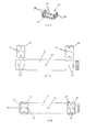
- Fig. 1a shows a bus board 2 for attachment to a housing wall 10 (FIG. Fig. 2a ) of a 36 mm (2 divisional / TE) wide DIN built-in housing with a 45 mm standard cutout. Shown is a contact side of the bus circuit board 2 with a pin header 4, with a female connector 6 and with spring contacts 8. By plugging pin headers 4 and female connectors 6 several bus circuit boards 2 creates an electrical and mechanical connection.
- Fig. 2a shows the housing wall 10 of the 2 TE-wide DIN-mounting housing with four integrated snap elements 12, which are designed as snap hook 12 and undetachably formed on the housing wall 10.
- the housing wall has a housing opening 9 corresponding to the spring contacts 8.
- FIG. 2b shows behind snapped bus conductor plate 2 each two of the snap hooks 12, the two longitudinal edges of the bus circuit board 2.
- recesses 14 FIG. Fig. 1a, 1b
- the snap hooks 12 are secured against lateral displacement relative to the bus circuit board 2.
- Fig. 3a shows analogously to Fig. 1 the contact side with pin strip 4, female connector 6 and spring contacts 8 of a bus circuit board 2 for attachment to a housing wall 10 (FIG. Fig. 3b ) of a 107.5 mm (6 TE) wide DIN-mount housing.
- the snapped onto the 6 TE housing wall 10 bus circuit board 2 is analogous to Fig. 2b in Fig. 3b shown.
- Fig. 4 shows a headband 16 for fastening the bus circuit board 2 to the housing wall 10 of a building housing ( Fig. 6a ).
- the retaining bracket 16 is U-shaped and consists essentially of a web 18 as a central part and two shorter leg parts. To the leg parts in each case two hooks 20 are formed, which in corresponding openings 26 (FIG. Fig. 6a ) of the housing wall 10 ( Fig. 6a ) are inserted and locked.
- the headband 16 has two circular elevations 17 which engage in corresponding detent bores 13 of the bus circuit board 2 (FIG. Fig. 5a ) engage and serve to lock the retaining clip 16.
- Fig. 5a the bus circuit board 2 is shown together with two retaining clips 16 in the unassembled state.
- the headband 16 are shown here before mounting in a position above the final mounting position.
- the recesses or cracks in the contour of the longitudinal edges of the bus board 2 - in Fig. 5a visible below the position in which the not yet mounted headband 16 are shown - prevent lateral displacement of the headband 16 along the bus board 2.
- the bus board 2 has a center hole 15 in the an integrally formed on the housing wall 10 centering pin 28 sets ( Fig. 6a, 6b ).
- the Fig. 5b shows the bus circuit board 2 with mounted brackets 16th
- Fig. 6a is exemplary, the housing wall 10 of a body assembly according to DIN EN 60715 with the unassembled bus circuit board 2 off FIG. 5b shown.
- the housing wall 10 has angular openings 26 into which the hooks 20 (FIG. Fig. 4 ) of the headband 16 are inserted and locked and thus secured against self-loosening.
- Fig. 6b shows the housing wall 10 of the body assembly with the fixed by the headband 16 on the housing wall 10 bus circuit board 2 from Fig. 5b ,
- the engaging in the center hole 15 of the bus board 2 centering pin 28 of the housing wall 10 causes a precise introduction of the spring contacts 8 in the housing opening 9.
- the centering pin 28 prevents in addition to the recesses or cracks in the contour of the longitudinal edges of the bus board 2, a lateral displacement of the bus board second
Landscapes
- Engineering & Computer Science (AREA)
- Automation & Control Theory (AREA)
- Microelectronics & Electronic Packaging (AREA)
- Coupling Device And Connection With Printed Circuit (AREA)
- Details Of Connecting Devices For Male And Female Coupling (AREA)
- Connector Housings Or Holding Contact Members (AREA)
Applications Claiming Priority (1)
| Application Number | Priority Date | Filing Date | Title |
|---|---|---|---|
| DE102014212969.9A DE102014212969A1 (de) | 2014-07-03 | 2014-07-03 | Busverbinder-System für elektrische Betriebsmittel |
Publications (3)
| Publication Number | Publication Date |
|---|---|
| EP2964005A2 true EP2964005A2 (fr) | 2016-01-06 |
| EP2964005A3 EP2964005A3 (fr) | 2016-01-20 |
| EP2964005B1 EP2964005B1 (fr) | 2022-12-07 |
Family
ID=53487231
Family Applications (1)
| Application Number | Title | Priority Date | Filing Date |
|---|---|---|---|
| EP15173126.2A Active EP2964005B1 (fr) | 2014-07-03 | 2015-06-22 | Systeme de connecteur de bus pour moyen de fonctionnement electrique |
Country Status (3)
| Country | Link |
|---|---|
| US (1) | US9509108B2 (fr) |
| EP (1) | EP2964005B1 (fr) |
| DE (1) | DE102014212969A1 (fr) |
Cited By (1)
| Publication number | Priority date | Publication date | Assignee | Title |
|---|---|---|---|---|
| EP3993190A1 (fr) * | 2020-11-03 | 2022-05-04 | Bender GmbH & Co. KG | Agencement de bus à rail de support avec adressage automatique de bus |
Citations (2)
| Publication number | Priority date | Publication date | Assignee | Title |
|---|---|---|---|---|
| DE202006006615U1 (de) | 2006-04-22 | 2006-09-07 | Phoenix Contact Gmbh & Co. Kg | Elektronikgehäuse |
| DE102006031129A1 (de) | 2005-07-12 | 2007-01-25 | E. Dold & Söhne KG | Gerätesystem mit auf einer Tragschiene montierten elektrischen Gerätemodulen und in der Tragschine angeordneter BUS-Leitung |
Family Cites Families (15)
| Publication number | Priority date | Publication date | Assignee | Title |
|---|---|---|---|---|
| US4790762A (en) * | 1985-07-23 | 1988-12-13 | Honeywell Inc. | Backplane for a modularly expandable programmable controller |
| US5532907A (en) * | 1993-11-02 | 1996-07-02 | International Business Machines Corporation | Computer system with improved power bus |
| DE29609635U1 (de) * | 1996-05-30 | 1996-08-22 | Siemens Nixdorf Informationssysteme AG, 33106 Paderborn | Haltevorrichtung für den Montagebügel von Steckkarten bzw. Standard-Flachbaugruppen |
| JPH1195807A (ja) * | 1997-09-17 | 1999-04-09 | Fuji Electric Co Ltd | プログラマブルコントローラのベースボード |
| DE29805305U1 (de) * | 1998-03-24 | 1999-07-22 | Robert Bosch Gmbh, 70469 Stuttgart | Elektrisches Gerät mit einer Halterung für plattenförmige Bauteile |
| US6542355B1 (en) * | 2000-09-29 | 2003-04-01 | Silitek Corporation | Waterproof keyboard |
| DE10116957A1 (de) * | 2001-04-05 | 2002-10-10 | Hella Kg Hueck & Co | Fahrzeugleuchte |
| DE20120478U1 (de) * | 2001-12-18 | 2003-04-24 | Tyco Electronics Ec Kft, Bicske | Halteelement, Baustein, insbesondere Powermodul und Gruppe von Leiterplatten |
| DE10259415A1 (de) * | 2002-12-19 | 2004-07-08 | Demag Ergotech Gmbh | Technologie-Platine mit modularer SPS-Integration und Erweiterung |
| JP2004226584A (ja) * | 2003-01-22 | 2004-08-12 | Fuji Xerox Co Ltd | 光信号伝送装置、及び信号処理装置 |
| TW573764U (en) * | 2003-06-18 | 2004-01-21 | Carry Computer Eng Co Ltd | Read integrating device |
| US7106595B2 (en) * | 2004-09-15 | 2006-09-12 | International Business Machines Corporation | Apparatus including a thermal bus on a circuit board for cooling components on a daughter card releasably attached to the circuit board |
| DE102010044065A1 (de) * | 2010-11-17 | 2012-05-24 | BSH Bosch und Siemens Hausgeräte GmbH | Elektronische Baueinheit |
| DE102012213258A1 (de) * | 2012-07-27 | 2014-01-30 | Siemens Aktiengesellschaft | Verbindungssystem |
| US9229504B1 (en) * | 2012-12-04 | 2016-01-05 | Amazon Technologies, Inc. | Power bus aggregated from shelf-level bus elements |
-
2014
- 2014-07-03 DE DE102014212969.9A patent/DE102014212969A1/de not_active Ceased
-
2015
- 2015-06-22 EP EP15173126.2A patent/EP2964005B1/fr active Active
- 2015-07-02 US US14/790,135 patent/US9509108B2/en not_active Expired - Fee Related
Patent Citations (2)
| Publication number | Priority date | Publication date | Assignee | Title |
|---|---|---|---|---|
| DE102006031129A1 (de) | 2005-07-12 | 2007-01-25 | E. Dold & Söhne KG | Gerätesystem mit auf einer Tragschiene montierten elektrischen Gerätemodulen und in der Tragschine angeordneter BUS-Leitung |
| DE202006006615U1 (de) | 2006-04-22 | 2006-09-07 | Phoenix Contact Gmbh & Co. Kg | Elektronikgehäuse |
Cited By (2)
| Publication number | Priority date | Publication date | Assignee | Title |
|---|---|---|---|---|
| EP3993190A1 (fr) * | 2020-11-03 | 2022-05-04 | Bender GmbH & Co. KG | Agencement de bus à rail de support avec adressage automatique de bus |
| US11818859B2 (en) | 2020-11-03 | 2023-11-14 | Bender Gmbh & Co. Kg | Carrier-rail bus assembly with automatic bus addressing |
Also Published As
| Publication number | Publication date |
|---|---|
| EP2964005B1 (fr) | 2022-12-07 |
| DE102014212969A1 (de) | 2016-01-07 |
| US20160006199A1 (en) | 2016-01-07 |
| EP2964005A3 (fr) | 2016-01-20 |
| US9509108B2 (en) | 2016-11-29 |
Similar Documents
| Publication | Publication Date | Title |
|---|---|---|
| DE102015114814B4 (de) | System aus Steckverbinder-Modulrahmen und Adapterelementen sowie modularen Steckverbinder mit einem solchen System | |
| DE102006003752A1 (de) | Kupplung | |
| DE102007004545A1 (de) | Elektrische Anschlussklemme | |
| DE102012107264A1 (de) | Anschlussmodul | |
| DE19644416C1 (de) | Kontaktelement zur elektrischen Kontaktierung von Leiterkarten mit einer vorderen Modulschiene eines Baugruppenträgers | |
| EP3257121A1 (fr) | Ensemble de plusieurs pieds encliquetables pour module et module | |
| DE10218567C5 (de) | Anschlusssystem | |
| DE102016116926A1 (de) | Überspannungsschutzmodul für einen modularen Steckverbinder | |
| EP3149816B1 (fr) | Adaptateur de montage de parasurtenseurs uni- ou multipolaires sous forme de modules embrochables, et utilisation d'un tel adaptateur | |
| EP2964005B1 (fr) | Systeme de connecteur de bus pour moyen de fonctionnement electrique | |
| DE102016124637B4 (de) | Anordnung von tragelementen und komponentenaufbausystem | |
| DE102012015037B4 (de) | Elektronikmodul | |
| EP3738175A1 (fr) | Ensemble connecteur enfichable | |
| WO2019224053A1 (fr) | Dispositif de contact avec fourche à ressort | |
| DE10047126B4 (de) | Befestigungseinrichtung | |
| DE202013100330U1 (de) | Modular aufgebaute Leiterplatten-Steckverbinderanordnung, Grundmodul und Aufstockmodul dafür | |
| DE102015110223B4 (de) | Baugruppe einer Klemmeneinrichtung zum Anschließen von elektrischen Leitern | |
| EP3577725B1 (fr) | Connecteur enfichable équipé d'un pont de connexion de conducteurs de protection | |
| EP1403970B1 (fr) | Dispositif d'attachement d' une boîte à un rail de montage | |
| DE202013104941U1 (de) | Elektrische Steckverbinderanordnung und Schirmanbindungselement hierzu | |
| DE19707777B4 (de) | Steckvorrichtung | |
| DE2558739C2 (de) | Rastende Steckverbindung | |
| DE2044151C3 (de) | Elektrischer Steckverbinder | |
| DE202015104735U1 (de) | Befestigungsstift zum Befestigen eines Kontaktelementes in einem Steckgehäuse einer Steckanordnung | |
| WO2022068992A1 (fr) | Système de fixation pour connecteur mâle |
Legal Events
| Date | Code | Title | Description |
|---|---|---|---|
| PUAL | Search report despatched |
Free format text: ORIGINAL CODE: 0009013 |
|
| PUAI | Public reference made under article 153(3) epc to a published international application that has entered the european phase |
Free format text: ORIGINAL CODE: 0009012 |
|
| AK | Designated contracting states |
Kind code of ref document: A2 Designated state(s): AL AT BE BG CH CY CZ DE DK EE ES FI FR GB GR HR HU IE IS IT LI LT LU LV MC MK MT NL NO PL PT RO RS SE SI SK SM TR |
|
| AX | Request for extension of the european patent |
Extension state: BA ME |
|
| AK | Designated contracting states |
Kind code of ref document: A3 Designated state(s): AL AT BE BG CH CY CZ DE DK EE ES FI FR GB GR HR HU IE IS IT LI LT LU LV MC MK MT NL NO PL PT RO RS SE SI SK SM TR |
|
| AX | Request for extension of the european patent |
Extension state: BA ME |
|
| RIC1 | Information provided on ipc code assigned before grant |
Ipc: H05K 7/14 20060101AFI20151216BHEP |
|
| 17P | Request for examination filed |
Effective date: 20160616 |
|
| RBV | Designated contracting states (corrected) |
Designated state(s): AL AT BE BG CH CY CZ DE DK EE ES FI FR GB GR HR HU IE IS IT LI LT LU LV MC MK MT NL NO PL PT RO RS SE SI SK SM TR |
|
| STAA | Information on the status of an ep patent application or granted ep patent |
Free format text: STATUS: EXAMINATION IS IN PROGRESS |
|
| 17Q | First examination report despatched |
Effective date: 20180208 |
|
| GRAP | Despatch of communication of intention to grant a patent |
Free format text: ORIGINAL CODE: EPIDOSNIGR1 |
|
| STAA | Information on the status of an ep patent application or granted ep patent |
Free format text: STATUS: GRANT OF PATENT IS INTENDED |
|
| GRAJ | Information related to disapproval of communication of intention to grant by the applicant or resumption of examination proceedings by the epo deleted |
Free format text: ORIGINAL CODE: EPIDOSDIGR1 |
|
| INTG | Intention to grant announced |
Effective date: 20220504 |
|
| STAA | Information on the status of an ep patent application or granted ep patent |
Free format text: STATUS: EXAMINATION IS IN PROGRESS |
|
| INTC | Intention to grant announced (deleted) | ||
| GRAP | Despatch of communication of intention to grant a patent |
Free format text: ORIGINAL CODE: EPIDOSNIGR1 |
|
| STAA | Information on the status of an ep patent application or granted ep patent |
Free format text: STATUS: GRANT OF PATENT IS INTENDED |
|
| INTG | Intention to grant announced |
Effective date: 20220721 |
|
| GRAS | Grant fee paid |
Free format text: ORIGINAL CODE: EPIDOSNIGR3 |
|
| GRAA | (expected) grant |
Free format text: ORIGINAL CODE: 0009210 |
|
| STAA | Information on the status of an ep patent application or granted ep patent |
Free format text: STATUS: THE PATENT HAS BEEN GRANTED |
|
| AK | Designated contracting states |
Kind code of ref document: B1 Designated state(s): AL AT BE BG CH CY CZ DE DK EE ES FI FR GB GR HR HU IE IS IT LI LT LU LV MC MK MT NL NO PL PT RO RS SE SI SK SM TR |
|
| REG | Reference to a national code |
Ref country code: GB Ref legal event code: FG4D Free format text: NOT ENGLISH |
|
| REG | Reference to a national code |
Ref country code: CH Ref legal event code: EP Ref country code: AT Ref legal event code: REF Ref document number: 1537109 Country of ref document: AT Kind code of ref document: T Effective date: 20221215 |
|
| REG | Reference to a national code |
Ref country code: DE Ref legal event code: R096 Ref document number: 502015016180 Country of ref document: DE |
|
| REG | Reference to a national code |
Ref country code: IE Ref legal event code: FG4D Free format text: LANGUAGE OF EP DOCUMENT: GERMAN |
|
| REG | Reference to a national code |
Ref country code: LT Ref legal event code: MG9D |
|
| REG | Reference to a national code |
Ref country code: NL Ref legal event code: MP Effective date: 20221207 |
|
| PG25 | Lapsed in a contracting state [announced via postgrant information from national office to epo] |
Ref country code: SE Free format text: LAPSE BECAUSE OF FAILURE TO SUBMIT A TRANSLATION OF THE DESCRIPTION OR TO PAY THE FEE WITHIN THE PRESCRIBED TIME-LIMIT Effective date: 20221207 Ref country code: NO Free format text: LAPSE BECAUSE OF FAILURE TO SUBMIT A TRANSLATION OF THE DESCRIPTION OR TO PAY THE FEE WITHIN THE PRESCRIBED TIME-LIMIT Effective date: 20230307 Ref country code: LT Free format text: LAPSE BECAUSE OF FAILURE TO SUBMIT A TRANSLATION OF THE DESCRIPTION OR TO PAY THE FEE WITHIN THE PRESCRIBED TIME-LIMIT Effective date: 20221207 Ref country code: FI Free format text: LAPSE BECAUSE OF FAILURE TO SUBMIT A TRANSLATION OF THE DESCRIPTION OR TO PAY THE FEE WITHIN THE PRESCRIBED TIME-LIMIT Effective date: 20221207 Ref country code: ES Free format text: LAPSE BECAUSE OF FAILURE TO SUBMIT A TRANSLATION OF THE DESCRIPTION OR TO PAY THE FEE WITHIN THE PRESCRIBED TIME-LIMIT Effective date: 20221207 |
|
| PG25 | Lapsed in a contracting state [announced via postgrant information from national office to epo] |
Ref country code: RS Free format text: LAPSE BECAUSE OF FAILURE TO SUBMIT A TRANSLATION OF THE DESCRIPTION OR TO PAY THE FEE WITHIN THE PRESCRIBED TIME-LIMIT Effective date: 20221207 Ref country code: PL Free format text: LAPSE BECAUSE OF FAILURE TO SUBMIT A TRANSLATION OF THE DESCRIPTION OR TO PAY THE FEE WITHIN THE PRESCRIBED TIME-LIMIT Effective date: 20221207 Ref country code: LV Free format text: LAPSE BECAUSE OF FAILURE TO SUBMIT A TRANSLATION OF THE DESCRIPTION OR TO PAY THE FEE WITHIN THE PRESCRIBED TIME-LIMIT Effective date: 20221207 Ref country code: HR Free format text: LAPSE BECAUSE OF FAILURE TO SUBMIT A TRANSLATION OF THE DESCRIPTION OR TO PAY THE FEE WITHIN THE PRESCRIBED TIME-LIMIT Effective date: 20221207 Ref country code: GR Free format text: LAPSE BECAUSE OF FAILURE TO SUBMIT A TRANSLATION OF THE DESCRIPTION OR TO PAY THE FEE WITHIN THE PRESCRIBED TIME-LIMIT Effective date: 20230308 |
|
| PG25 | Lapsed in a contracting state [announced via postgrant information from national office to epo] |
Ref country code: NL Free format text: LAPSE BECAUSE OF FAILURE TO SUBMIT A TRANSLATION OF THE DESCRIPTION OR TO PAY THE FEE WITHIN THE PRESCRIBED TIME-LIMIT Effective date: 20221207 |
|
| P01 | Opt-out of the competence of the unified patent court (upc) registered |
Effective date: 20230525 |
|
| PG25 | Lapsed in a contracting state [announced via postgrant information from national office to epo] |
Ref country code: SM Free format text: LAPSE BECAUSE OF FAILURE TO SUBMIT A TRANSLATION OF THE DESCRIPTION OR TO PAY THE FEE WITHIN THE PRESCRIBED TIME-LIMIT Effective date: 20221207 Ref country code: RO Free format text: LAPSE BECAUSE OF FAILURE TO SUBMIT A TRANSLATION OF THE DESCRIPTION OR TO PAY THE FEE WITHIN THE PRESCRIBED TIME-LIMIT Effective date: 20221207 Ref country code: PT Free format text: LAPSE BECAUSE OF FAILURE TO SUBMIT A TRANSLATION OF THE DESCRIPTION OR TO PAY THE FEE WITHIN THE PRESCRIBED TIME-LIMIT Effective date: 20230410 Ref country code: EE Free format text: LAPSE BECAUSE OF FAILURE TO SUBMIT A TRANSLATION OF THE DESCRIPTION OR TO PAY THE FEE WITHIN THE PRESCRIBED TIME-LIMIT Effective date: 20221207 Ref country code: CZ Free format text: LAPSE BECAUSE OF FAILURE TO SUBMIT A TRANSLATION OF THE DESCRIPTION OR TO PAY THE FEE WITHIN THE PRESCRIBED TIME-LIMIT Effective date: 20221207 |
|
| PGFP | Annual fee paid to national office [announced via postgrant information from national office to epo] |
Ref country code: FR Payment date: 20230622 Year of fee payment: 9 Ref country code: DE Payment date: 20230620 Year of fee payment: 9 |
|
| PG25 | Lapsed in a contracting state [announced via postgrant information from national office to epo] |
Ref country code: SK Free format text: LAPSE BECAUSE OF FAILURE TO SUBMIT A TRANSLATION OF THE DESCRIPTION OR TO PAY THE FEE WITHIN THE PRESCRIBED TIME-LIMIT Effective date: 20221207 Ref country code: IS Free format text: LAPSE BECAUSE OF FAILURE TO SUBMIT A TRANSLATION OF THE DESCRIPTION OR TO PAY THE FEE WITHIN THE PRESCRIBED TIME-LIMIT Effective date: 20230407 Ref country code: AL Free format text: LAPSE BECAUSE OF FAILURE TO SUBMIT A TRANSLATION OF THE DESCRIPTION OR TO PAY THE FEE WITHIN THE PRESCRIBED TIME-LIMIT Effective date: 20221207 |
|
| REG | Reference to a national code |
Ref country code: DE Ref legal event code: R097 Ref document number: 502015016180 Country of ref document: DE |
|
| PLBE | No opposition filed within time limit |
Free format text: ORIGINAL CODE: 0009261 |
|
| STAA | Information on the status of an ep patent application or granted ep patent |
Free format text: STATUS: NO OPPOSITION FILED WITHIN TIME LIMIT |
|
| PG25 | Lapsed in a contracting state [announced via postgrant information from national office to epo] |
Ref country code: DK Free format text: LAPSE BECAUSE OF FAILURE TO SUBMIT A TRANSLATION OF THE DESCRIPTION OR TO PAY THE FEE WITHIN THE PRESCRIBED TIME-LIMIT Effective date: 20221207 |
|
| PGFP | Annual fee paid to national office [announced via postgrant information from national office to epo] |
Ref country code: GB Payment date: 20230622 Year of fee payment: 9 |
|
| 26N | No opposition filed |
Effective date: 20230908 |
|
| PG25 | Lapsed in a contracting state [announced via postgrant information from national office to epo] |
Ref country code: SI Free format text: LAPSE BECAUSE OF FAILURE TO SUBMIT A TRANSLATION OF THE DESCRIPTION OR TO PAY THE FEE WITHIN THE PRESCRIBED TIME-LIMIT Effective date: 20221207 |
|
| PG25 | Lapsed in a contracting state [announced via postgrant information from national office to epo] |
Ref country code: MC Free format text: LAPSE BECAUSE OF FAILURE TO SUBMIT A TRANSLATION OF THE DESCRIPTION OR TO PAY THE FEE WITHIN THE PRESCRIBED TIME-LIMIT Effective date: 20221207 |
|
| PG25 | Lapsed in a contracting state [announced via postgrant information from national office to epo] |
Ref country code: MC Free format text: LAPSE BECAUSE OF FAILURE TO SUBMIT A TRANSLATION OF THE DESCRIPTION OR TO PAY THE FEE WITHIN THE PRESCRIBED TIME-LIMIT Effective date: 20221207 |
|
| REG | Reference to a national code |
Ref country code: CH Ref legal event code: PL |
|
| REG | Reference to a national code |
Ref country code: BE Ref legal event code: MM Effective date: 20230630 |
|
| PG25 | Lapsed in a contracting state [announced via postgrant information from national office to epo] |
Ref country code: LU Free format text: LAPSE BECAUSE OF NON-PAYMENT OF DUE FEES Effective date: 20230622 |
|
| REG | Reference to a national code |
Ref country code: IE Ref legal event code: MM4A |
|
| PG25 | Lapsed in a contracting state [announced via postgrant information from national office to epo] |
Ref country code: LU Free format text: LAPSE BECAUSE OF NON-PAYMENT OF DUE FEES Effective date: 20230622 |
|
| PG25 | Lapsed in a contracting state [announced via postgrant information from national office to epo] |
Ref country code: IE Free format text: LAPSE BECAUSE OF NON-PAYMENT OF DUE FEES Effective date: 20230622 |
|
| PG25 | Lapsed in a contracting state [announced via postgrant information from national office to epo] |
Ref country code: IE Free format text: LAPSE BECAUSE OF NON-PAYMENT OF DUE FEES Effective date: 20230622 Ref country code: CH Free format text: LAPSE BECAUSE OF NON-PAYMENT OF DUE FEES Effective date: 20230630 |
|
| PG25 | Lapsed in a contracting state [announced via postgrant information from national office to epo] |
Ref country code: IT Free format text: LAPSE BECAUSE OF FAILURE TO SUBMIT A TRANSLATION OF THE DESCRIPTION OR TO PAY THE FEE WITHIN THE PRESCRIBED TIME-LIMIT Effective date: 20221207 Ref country code: BE Free format text: LAPSE BECAUSE OF NON-PAYMENT OF DUE FEES Effective date: 20230630 |
|
| REG | Reference to a national code |
Ref country code: AT Ref legal event code: MM01 Ref document number: 1537109 Country of ref document: AT Kind code of ref document: T Effective date: 20230622 |
|
| PG25 | Lapsed in a contracting state [announced via postgrant information from national office to epo] |
Ref country code: AT Free format text: LAPSE BECAUSE OF NON-PAYMENT OF DUE FEES Effective date: 20230622 |
|
| PG25 | Lapsed in a contracting state [announced via postgrant information from national office to epo] |
Ref country code: AT Free format text: LAPSE BECAUSE OF NON-PAYMENT OF DUE FEES Effective date: 20230622 |
|
| PG25 | Lapsed in a contracting state [announced via postgrant information from national office to epo] |
Ref country code: BG Free format text: LAPSE BECAUSE OF FAILURE TO SUBMIT A TRANSLATION OF THE DESCRIPTION OR TO PAY THE FEE WITHIN THE PRESCRIBED TIME-LIMIT Effective date: 20221207 |
|
| PG25 | Lapsed in a contracting state [announced via postgrant information from national office to epo] |
Ref country code: BG Free format text: LAPSE BECAUSE OF FAILURE TO SUBMIT A TRANSLATION OF THE DESCRIPTION OR TO PAY THE FEE WITHIN THE PRESCRIBED TIME-LIMIT Effective date: 20221207 |
|
| REG | Reference to a national code |
Ref country code: DE Ref legal event code: R119 Ref document number: 502015016180 Country of ref document: DE |
|
| GBPC | Gb: european patent ceased through non-payment of renewal fee |
Effective date: 20240622 |
|
| PG25 | Lapsed in a contracting state [announced via postgrant information from national office to epo] |
Ref country code: DE Free format text: LAPSE BECAUSE OF NON-PAYMENT OF DUE FEES Effective date: 20250101 |
|
| PG25 | Lapsed in a contracting state [announced via postgrant information from national office to epo] |
Ref country code: FR Free format text: LAPSE BECAUSE OF NON-PAYMENT OF DUE FEES Effective date: 20240630 |
|
| PG25 | Lapsed in a contracting state [announced via postgrant information from national office to epo] |
Ref country code: GB Free format text: LAPSE BECAUSE OF NON-PAYMENT OF DUE FEES Effective date: 20240622 |
|
| PG25 | Lapsed in a contracting state [announced via postgrant information from national office to epo] |
Ref country code: CY Free format text: LAPSE BECAUSE OF FAILURE TO SUBMIT A TRANSLATION OF THE DESCRIPTION OR TO PAY THE FEE WITHIN THE PRESCRIBED TIME-LIMIT; INVALID AB INITIO Effective date: 20150622 |
|
| PG25 | Lapsed in a contracting state [announced via postgrant information from national office to epo] |
Ref country code: HU Free format text: LAPSE BECAUSE OF FAILURE TO SUBMIT A TRANSLATION OF THE DESCRIPTION OR TO PAY THE FEE WITHIN THE PRESCRIBED TIME-LIMIT; INVALID AB INITIO Effective date: 20150622 |
|
| PG25 | Lapsed in a contracting state [announced via postgrant information from national office to epo] |
Ref country code: TR Free format text: LAPSE BECAUSE OF FAILURE TO SUBMIT A TRANSLATION OF THE DESCRIPTION OR TO PAY THE FEE WITHIN THE PRESCRIBED TIME-LIMIT Effective date: 20221207 |