EP2964112B1 - Système d'outil médical - Google Patents
Système d'outil médical Download PDFInfo
- Publication number
- EP2964112B1 EP2964112B1 EP14701011.0A EP14701011A EP2964112B1 EP 2964112 B1 EP2964112 B1 EP 2964112B1 EP 14701011 A EP14701011 A EP 14701011A EP 2964112 B1 EP2964112 B1 EP 2964112B1
- Authority
- EP
- European Patent Office
- Prior art keywords
- tool
- guide
- milling
- carriage
- tool system
- Prior art date
- Legal status (The legal status is an assumption and is not a legal conclusion. Google has not performed a legal analysis and makes no representation as to the accuracy of the status listed.)
- Active
Links
Images


Classifications
-
- A—HUMAN NECESSITIES
- A61—MEDICAL OR VETERINARY SCIENCE; HYGIENE
- A61B—DIAGNOSIS; SURGERY; IDENTIFICATION
- A61B17/00—Surgical instruments, devices or methods
- A61B17/16—Instruments for performing osteoclasis; Drills or chisels for bones; Trepans
- A61B17/1613—Component parts
- A61B17/162—Chucks or tool parts which are to be held in a chuck
-
- A—HUMAN NECESSITIES
- A61—MEDICAL OR VETERINARY SCIENCE; HYGIENE
- A61B—DIAGNOSIS; SURGERY; IDENTIFICATION
- A61B17/00—Surgical instruments, devices or methods
- A61B17/16—Instruments for performing osteoclasis; Drills or chisels for bones; Trepans
- A61B17/1662—Instruments for performing osteoclasis; Drills or chisels for bones; Trepans for particular parts of the body
- A61B17/1675—Instruments for performing osteoclasis; Drills or chisels for bones; Trepans for particular parts of the body for the knee
-
- A—HUMAN NECESSITIES
- A61—MEDICAL OR VETERINARY SCIENCE; HYGIENE
- A61B—DIAGNOSIS; SURGERY; IDENTIFICATION
- A61B17/00—Surgical instruments, devices or methods
- A61B17/16—Instruments for performing osteoclasis; Drills or chisels for bones; Trepans
- A61B17/17—Guides or aligning means for drills, mills, pins or wires
- A61B17/1739—Guides or aligning means for drills, mills, pins or wires specially adapted for particular parts of the body
- A61B17/1764—Guides or aligning means for drills, mills, pins or wires specially adapted for particular parts of the body for the knee
-
- A—HUMAN NECESSITIES
- A61—MEDICAL OR VETERINARY SCIENCE; HYGIENE
- A61B—DIAGNOSIS; SURGERY; IDENTIFICATION
- A61B90/00—Instruments, implements or accessories specially adapted for surgery or diagnosis and not covered by any of the groups A61B1/00 - A61B50/00, e.g. for luxation treatment or for protecting wound edges
- A61B90/03—Automatic limiting or abutting means, e.g. for safety
-
- A—HUMAN NECESSITIES
- A61—MEDICAL OR VETERINARY SCIENCE; HYGIENE
- A61B—DIAGNOSIS; SURGERY; IDENTIFICATION
- A61B17/00—Surgical instruments, devices or methods
- A61B17/16—Instruments for performing osteoclasis; Drills or chisels for bones; Trepans
- A61B2017/1602—Mills
-
- A—HUMAN NECESSITIES
- A61—MEDICAL OR VETERINARY SCIENCE; HYGIENE
- A61B—DIAGNOSIS; SURGERY; IDENTIFICATION
- A61B90/00—Instruments, implements or accessories specially adapted for surgery or diagnosis and not covered by any of the groups A61B1/00 - A61B50/00, e.g. for luxation treatment or for protecting wound edges
- A61B90/03—Automatic limiting or abutting means, e.g. for safety
- A61B2090/033—Abutting means, stops, e.g. abutting on tissue or skin
- A61B2090/034—Abutting means, stops, e.g. abutting on tissue or skin abutting on parts of the device itself
Definitions
- the present invention relates to a medical tool system for preparing a trapezoidal recess in a joint surface of a bone with the features of the preamble of claim 1.
- Such partial dentures are often anchored with strip-shaped or differently shaped projections in the bone, for example with so-called fins.
- These Finns with a certain excess in a corresponding in the Bone material created recess or an evacuated groove are pressed, are often trapezoidal in cross section formed.
- attachment mechanisms can not only be used with partial implants, but also for other implants to be fixed to the bone, even for total replacement prosthetics.
- tool systems for broaching bone material are known in which templates interact with milling to be able to create recesses of predetermined shape and depth.
- Such a tool system which is used for milling recesses of a given contour is in the DE 603 20 485 T2 disclosed.
- a milling tool is used in a plate-like template in a guide slot used, which has a Having a radius milling head and due to the given leadership clears a cassette-like clearance.
- T2 is a system with a template and a milling tool guided therein disclosed for the preparation of the Kondylen lake a knee prosthesis.
- the rotary shaft of the milling cutter leads substantially vertically upward, requires a large clearance, so that the femoral part of the knee must be set far back during the operation and the preparation phase, with the aim of preserving the soft tissues of the joint, in particular the ligaments, here in particular the cruciate ligaments, can not be reconciled.
- an implant system for a partial replacement of the knee with a unilaterally replaced condylar surface and also to be attached on one side of the femur joint surface implant is known, which is sold by the US company Stryker Corporation under the brand EIUS TM.
- a preparation tool is provided, in which a trapezoidal recess is formed in the to be supplied Kondylen preparation the tibia.
- a template part is provided with a plate member having a fixedly connected to the plate member, having a rectangular cross-section tubular portion which forms a tool tunnel which extends at approximately 45 ° inclined to the plane of the plate.
- a drilling template is first used in this tunnel, and weakening holes are introduced into the bone material. Subsequently, the drill bit is removed and the thus perforated bone is finished by a clearing tool also inserted through the tunnel to form the recess into which the fin of the condylar implant is inserted.
- the tool system has many parts and the associated method of forming the recess is cumbersome. Because it must be here with various tools initially introduced the holes and then made the final clearance of the recess. This procedure costs valuable operating time and, moreover, means that a large number of parts and instruments must be cleaned and disinfected following the operation.
- this tool system should be suitable for mounting such a trapezoidal recess in a condylar surface of the tibial component of the knee joint, e.g. for preparing to place a partial replacement prosthesis in this area.
- the novel medical tool system for preparing a trapezoidal recess in a joint surface of a bone has - and this first in accordance with known comparable tool systems - a drivable around a tool axis for rotation milling tool, which has circumferentially acting milling cutters and also milling cutters on one acting on the tool axis axial end. It also has - and also in accordance with prior art comparable tool systems - a fixable on the articular surface template part for guiding the milling tool, and it is provided a penetration depth of the milling tool limiting stop.
- the special feature of the tool system according to the invention consists in the fact that the template part has a base element with a Carriage guide and further in the carriage guide between two end stops along a guide track lying in a guide track movable carriage. Further, according to the invention, a guide channel for receiving the milling tool is formed in the carriage. In this guide channel, the milling tool received therein is then guided transversely to the tool axis, ie it can not move in a direction transverse to this tool axis relative to the guide channel. In the guide channel, however, the milling tool can rotate freely about the tool axis and be moved in the axial direction.
- the tool system according to the invention can be used, for example, to form a trapezoidal recess on a condylar surface of the tibial part of a knee joint, which is particularly suitable for this purpose.
- a condylar surface for setting a prosthetic implant it is first prepared in a cross-section taken transversely to the longitudinal axis of the tibia and a cross-section cut across this section in such a way that a flat plateau is formed there. In this plane plateau then a trapezoidal recess is introduced into which an anchoring process, typically referred to as a fin, a corresponding implant can be pressed.
- the base element of the template part of the tool system according to the invention is placed and in particular fixed after preparation of the flat plateau on the then resulting surface.
- the carriage which can be moved back and forth on the base element in the slide guide between the two end stops, can now glide back and forth between these end stops, corresponding space is also available in minimally invasive surgical techniques.
- the milling tool is introduced and set in rotation. In this case, the milling tool cuts into the bone surface, this at the preset angle of inclination of the guide channel relative to the guide plane.
- the stop prevents the milling tool from penetrating too deeply into the bone and determines the depth of the recess.
- the milling tool has both in the circumferential direction and in the direction of the axial end acting milling cutters, it admits the recess at a formed by the axial end of the cutter flank, which is formed when the carriage maximum in a feed direction of the milling tool in the carriage guide moved to the end stop and the milling tool is inserted all the way into the guide channel, smooth and clean.
- the inclination of the guide channel on the carriage is in particular such that a pointing away from the management level portion of a front, that is located proximal to be applied during surgery end of the carriage is located.
- the base element plate-shaped and flat.
- the base element adapts particularly well to the surface that has just been prepared, after the condyle cut.
- a plate-shaped base element to achieve a particularly low height, which in view of the above-mentioned objectives of a minimum intervention in the natural Joint structure is beneficial.
- the thickness of the plate-shaped base element will usually be chosen such that a sufficiently stable and accurate guidance of the carriage is possible, at the same time the lowest possible strength is set.
- the carriage guide can be formed in the base element by a straight longitudinal slot in which a guide extension of the guide carriage is received.
- a slide guide is technically simple to realize and easy to operate; on the other hand, it is the ideal guide for the formation of a straight, trapezoidal-shaped recess.
- the trapezoidal shape of the recess arises due to the position of the axis of the milling tool which is inclined to a substrate of the recess and also to the flat surface remaining after the condyle section.
- a front boundary surface is obliquely following this axial position
- a rear boundary surface is obliquely formed due to the milling cutters acting on the axial end, in particular when the milling cutters acting on the axial end relative to the tool axis mill a surface substantially during milling plan and perpendicular to the axis of rotation.
- the milling cutter can have a cylindrical outer contour with a free axial end which runs substantially perpendicular to the tool axis and with milling edges along the circumference and at the front end.
- the guide channel is advantageously inclined relative to the guide plane by an angle of 30 ° to 60 °, in particular at an angle of 40 ° to 50 °, wherein a slope by an angle of 45 ° is particularly preferred.
- the said angular ranges result in such inclined positions of the milling tool, which intervene no longer disturbing and expansive in the actual joint area, taking into account the long to be connected to a milling drive cutter shaft, ie the area in which the set aside for the operation partner bone of the articular surface to be machined bone is located and the soft tissues of the joint are.
- the solution according to the invention differs significantly from the DE 60 2004 013 383 T2 , which has a considerable amount of space there due to the vertical guidance of the cutter shaft.
- an angle of 45 ° since with this a trapezoidal recess is created, the lateral, obliquely extending boundary surfaces both extend at an angle of 45 °.
- the first follows the inclination of the tool axis with respect to the guide plane; the second side surface is tilted accordingly tilted by 90 °, ie by 45 ° relative to the guide surface in the other orientation.
- This difference of 90 ° is due to the design of the milling tool, which at its axial end a vertically extending to the tool axis surface portion aus, thus acting milling cutters.
- the guide channel may be arranged in a tubular portion of the carriage having an upper edge.
- the milling tool has in this development on a transverse to the axis of rotation protruding collar.
- the edge of the tubular portion and the collar together form the stop, via which the penetration depth of the milling tool is limited in the guide channel and thus the working depth in the bone material, so as to determine the depth of the trapezoidal recess and comply exactly.
- slide and base elements can advantageously be detachably connected to one another. This prevents in particular the need for cleaning or sterilization of otherwise possibly existing gaps in the region of the movable connection.
- the base element of the template part with Advantage have pinholes.
- Such pin holes are passage openings through which fastening pins or screws, so-called plug pins or screw pins in previously introduced into the bone holes can be used.
- Such pins are well known and widely used in orthopedic surgery for securing auxiliary devices and tool guides.
- a handle section can be formed on the base element.
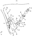
- the tool system according to the invention is generally designated 1 in the figures and comprises a rotary drivable milling tool 2 and a template part 3.
- the template part 3 in turn is in two parts formed with a base member 4 and a fixable to the base member 4, movable in a traversing direction between two attachment points carriage 5th
- the milling tool 2 is formed extending in an axial direction and has at a reaming milling cutting edges 6, on the one hand circumferentially act, on the other hand unfold at its front end a mecanicn syndromem Mann along a clearing surface, which is substantially perpendicular to the longitudinal axis 7 of the milling tool. 2
- the milling tool 2 has a Coupling connection 8 on for connection to a rotary drive.
- a cylinder portion 9 extends to an annular circumferential thickening 10, which is greater in diameter than the diameter of the cylinder portion.
- the template part 3 is, as already stated, constructed in two parts and consists of a base member 4 and on this base member 4 releasably fixable, guided in a fixed state in a carriage guide slide 5.
- the base member 4 is plate-shaped with a handle portion 11, to which this can be grasped and held in use. It also has a longitudinal slot 12, which is opened by a circular bore 13 with respect to the slot width expanded diameter at a position.
- a tool passage recess 15 is formed in a roughly semicircularly formed support section 14.
- a total of four pin holes 16 are arranged on the base element 4.
- the carriage 5 has on its underside a guide pin, which ends with a circular retaining plate 17.
- the diameter of this circular retaining plate 17 is approximately equal to the diameter of the circular bore 13, so that the retaining plate 17 can be guided through the circular bore 13 to bring the effetspin the carriage in the longitudinal slot 12 for longitudinal guidance of the carriage 5 and there in all positions with Exception of the position in which the retaining plate 17 and the circular bore 13 are exactly aligned to lock.
- a guide channel 18 is formed, which is formed by a peripheral edge 19 having a guide opening and an adjoining, a circumferential cylindrical wall having channel.
- the diameter of the guide channel 18 substantially corresponds to the diameter of the cylinder portion 9, so that the milling tool 2 can be used with its equipped with milling cutters 6ntendednde ahead in the guide channel 18 and rotate laterally guided safely.
- a shield section 20 is arranged in extension of the guide channel 18, which serves to cover the milling cutters 6 in this area during use of the tool system 1 and in particular during insertion of the milling tool 2 with its broaching end in the forward direction Guide channel 18 to prevent unwanted injury to be obtained surrounding tissue or bone sections.
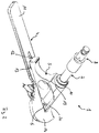
- Fig. 2 is that in Fig. 1 shown in exploded view tool system 1 in a comparable perspective in an assembled state.
- the peripheral edge 19 forms at the guide opening in the guide channel 18 together with the annular thickening 10 on the milling tool 2 a the depth of penetration of the equipped with milling cutters 6 broaching end of the milling tool 2 stop.
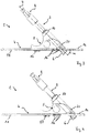
- Fig. 3 is shown in a side view, as with the carriage 5 located in a limited by the rear end of the longitudinal slot 12 stop position and at maximum deep in the guide channel dipped milling tool 2 whose broaching end with the Fräshunt 6 to a working depth over a plane of the plate Base element 4 protrudes.
- ⁇ is also included between the plate plane and the longitudinal axis 7 of the milling tool 2 angle ⁇ , which is here with preference 45 °.
- Fig. 4 is in one of the Fig. 3 comparable position shown the medical tool system 1 in such a position in which the carriage 5 is in a front stop position, which is determined by the front end of the longitudinal slot 12.
- Fig. 5 is a top view of the tool system 1 shown in a view from below.
- the guidance of the carriage 5 by the interaction of the held with the retaining plate 17 pins in the longitudinal slot 12 can be clearly seen.
- an implant part I shown with a fin F which is trapezoidal in cross-section and forms an anchoring element for the implant part I for fixing the same to a bone.
- the medical tool system 1 serves to bring one of the shape of the fin F substantially corresponding recess in a bone or to clear out of the bone material.
- FIGS. 6 and 7 Once again, very well, as happens in practice.
- the tool system 1 shown in a partial view and representation in front of the implant part I with the fin F.
- Fig. 6 the system is shown with the carriage 5 in the maximum retracted position. It can be seen here how the circumferential course of the broaching end 2 equipped with milling cutters 6 in the figure on the right essentially follows the course of the fin F in this area.
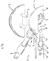
- FIGS. 8 and 9 Such a use in practice is in the FIGS. 8 and 9 shown from two different views. There is shown how this is done for the Forming a corresponding recess for anchoring an implant part for a knee replacement prosthesis provided tooling system 1 is used.
- the distal end of the femur Fe and the proximal end of the tibia Ti can be seen here.
- a plateau At the proximal end of the tibia Ti, a plateau has been previously created on one side by a horizontal section, on which the base part 4 of the tool system 1 is placed with its support section 14.
- the base part 4 is aligned according to the position of the recess to be introduced and (not shown here) fixed by introducing one or more retaining pins through one or more of the pin holes 16 into the bone in this position.
- the carriage 5 is applied and fixed to the base member 4 in the longitudinal slot for longitudinal guidance, and it is the milling tool 2 passed through the guide channel in the carriage 5 and by reciprocating the carriage 5 with up to the stop inserted milling tool 2 in the Cross-section trapezoidal recess precisely applied.
- the milling tool 2 with its axis safely protrudes from the area in which a particularly small gap is left between tibia Ti and femur Fe.
- the femur Fe does not have to be separated as far from the tibia Ti as usual, so that a soft-tissue-friendly operation is possible, in particular while preserving the natural ligaments, in particular the cruciate ligaments.
- the shield section 20 prevents the femur Fe or adjacent soft parts from being damaged inadvertently when working with the milling tool 2 because the shield section 20 securely shields the broaching end of the milling tool 2 with the milling cutters there.
Landscapes
- Health & Medical Sciences (AREA)
- Surgery (AREA)
- Life Sciences & Earth Sciences (AREA)
- Medical Informatics (AREA)
- Animal Behavior & Ethology (AREA)
- Veterinary Medicine (AREA)
- Oral & Maxillofacial Surgery (AREA)
- Engineering & Computer Science (AREA)
- Biomedical Technology (AREA)
- Heart & Thoracic Surgery (AREA)
- Public Health (AREA)
- Molecular Biology (AREA)
- Nuclear Medicine, Radiotherapy & Molecular Imaging (AREA)
- General Health & Medical Sciences (AREA)
- Dentistry (AREA)
- Orthopedic Medicine & Surgery (AREA)
- Pathology (AREA)
- Surgical Instruments (AREA)
- Prostheses (AREA)
- Dental Tools And Instruments Or Auxiliary Dental Instruments (AREA)
Claims (9)
- Système d'outil médical pour la préparation d'un évidement de forme trapézoïdale dans une surface d'une articulation d'un os (Ti), comprenant un outil de fraisage (2) pouvant être entraîné en rotation autour d'un axe d'outil (7), lequel présente des arêtes de fraisage (6) agissant du côté périphérique et des arêtes de fraisage (6) agissant à une extrémité axiale par rapport à l'axe d'outil (7), et comprenant une partie de gabarit (3) pouvant être fixée à la surface de l'articulation pour guider l'outil de fraisage (2), une butée (10, 19) limitant une profondeur de pénétration de l'outil de fraisage (2) étant prévue, la partie de gabarit (3) présentant un élément de base (4) avec un guidage de chariot (12) et un chariot (5) pouvant être guidé dans le guidage de chariot (12) entre deux butées de fin de course le long d'une trajectoire de guidage située dans un plan de guidage, un canal de guidage (18) étant formé dans le chariot (5) pour recevoir l'outil de fraisage (2) de manière guidée transversalement à l'axe d'outil (7) de telle sorte que l'outil de fraisage (2) puisse tourner librement autour de l'axe d'outil (7), caractérisé en ce que le canal de guidage (18) s'étend obliquement par rapport au plan de guidage et est incliné d'un angle de 30° à 60° par rapport au plan de guidage.
- Système d'outil selon la revendication 1, caractérisé en ce que l'élément de base (4) est réalisé en forme de plaque et sous forme plane.
- Système d'outil selon l'une quelconque des revendications précédentes, caractérisé en ce que le guide de chariot (12) est formé dans l'élément de base (4) par une fente longitudinale s'étendant en ligne droite, dans laquelle est reçue une saillie de guidage du chariot de guidage (5).
- Système d'outil selon l'une quelconque des revendications précédentes, caractérisé en ce que le canal de guidage (18) est incliné par rapport au plan de guidage suivant un angle de 400° à 50°, en particulier suivant un angle de 45°.
- Système d'outil selon l'une quelconque des revendications précédentes, caractérisé en ce que les arêtes de fraisage (6) agissant au niveau de l'extrémité axiale par rapport à l'axe d'outil (7) fraisent au cours du fraisage une surface qui est essentiellement plane et perpendiculaire à l'axe d'outil (7).
- Système d'outil selon l'une quelconque des revendications précédentes, caractérisé en ce que le canal de guidage (18) est disposé dans une portion tubulaire du chariot (5), qui présente le bord supérieur (19) et en ce que l'outil de fraisage (2) présente un col (10) faisant saillie transversalement à l'axe d'outil, le bord (19) et le col (10) formant ensemble la butée (10, 19).
- Système d'outil selon l'une quelconque des revendications précédentes, caractérisé en ce que le chariot (5) et l'élément de base (4) de la partie de gabarit (3) sont connectés l'un à l'autre de manière détachable.
- Système d'outil selon l'une quelconque des revendications précédentes, caractérisé par des trous de goupille (16) dans l'élément de base (4).
- Système d'outil selon l'une quelconque des revendications précédentes, caractérisé par une portion de poignée (11) au niveau de l'élément de base (4).
Priority Applications (1)
| Application Number | Priority Date | Filing Date | Title |
|---|---|---|---|
| EP14701011.0A EP2964112B1 (fr) | 2013-03-05 | 2014-01-16 | Système d'outil médical |
Applications Claiming Priority (3)
| Application Number | Priority Date | Filing Date | Title |
|---|---|---|---|
| EP13157855.1A EP2774555A1 (fr) | 2013-03-05 | 2013-03-05 | Système d'outil médical |
| EP14701011.0A EP2964112B1 (fr) | 2013-03-05 | 2014-01-16 | Système d'outil médical |
| PCT/EP2014/050797 WO2014135293A1 (fr) | 2013-03-05 | 2014-01-16 | Système d'outil médical |
Publications (2)
| Publication Number | Publication Date |
|---|---|
| EP2964112A1 EP2964112A1 (fr) | 2016-01-13 |
| EP2964112B1 true EP2964112B1 (fr) | 2017-03-22 |
Family
ID=47790096
Family Applications (2)
| Application Number | Title | Priority Date | Filing Date |
|---|---|---|---|
| EP13157855.1A Withdrawn EP2774555A1 (fr) | 2013-03-05 | 2013-03-05 | Système d'outil médical |
| EP14701011.0A Active EP2964112B1 (fr) | 2013-03-05 | 2014-01-16 | Système d'outil médical |
Family Applications Before (1)
| Application Number | Title | Priority Date | Filing Date |
|---|---|---|---|
| EP13157855.1A Withdrawn EP2774555A1 (fr) | 2013-03-05 | 2013-03-05 | Système d'outil médical |
Country Status (14)
| Country | Link |
|---|---|
| US (1) | US10194925B2 (fr) |
| EP (2) | EP2774555A1 (fr) |
| JP (1) | JP6263204B2 (fr) |
| KR (1) | KR101764518B1 (fr) |
| CN (1) | CN105007839B (fr) |
| AR (1) | AR094980A1 (fr) |
| AU (1) | AU2014224939B2 (fr) |
| BR (1) | BR112015018813A2 (fr) |
| CA (1) | CA2904423C (fr) |
| ES (1) | ES2624418T3 (fr) |
| IL (1) | IL241083B (fr) |
| MX (1) | MX361634B (fr) |
| RU (1) | RU2618922C2 (fr) |
| WO (1) | WO2014135293A1 (fr) |
Families Citing this family (7)
| Publication number | Priority date | Publication date | Assignee | Title |
|---|---|---|---|---|
| EP2651341B1 (fr) | 2010-12-16 | 2017-01-04 | Engage Medical Holdings, LLC | Systèmes et procédés d'arthroplastie |
| US20180078264A1 (en) | 2014-03-03 | 2018-03-22 | Biomet Uk Healthcare Limited | Rotary mill |
| GB2518891B (en) | 2013-10-07 | 2020-03-18 | Biomet Uk Healthcare Ltd | Rotary mill |
| CN105411635B (zh) * | 2015-12-22 | 2017-12-15 | 雷俊虎 | 膝关节前交叉韧带股骨隧道出针方向导向定位系统 |
| US10456272B2 (en) * | 2017-03-03 | 2019-10-29 | Engage Uni Llc | Unicompartmental knee arthroplasty |
| US11540928B2 (en) | 2017-03-03 | 2023-01-03 | Engage Uni Llc | Unicompartmental knee arthroplasty |
| CN111340876A (zh) * | 2020-02-21 | 2020-06-26 | 京东方科技集团股份有限公司 | 用于膝关节置换的处理方法、装置、存储介质和电子设备 |
Family Cites Families (17)
| Publication number | Priority date | Publication date | Assignee | Title |
|---|---|---|---|---|
| SU858791A1 (ru) * | 1979-11-01 | 1981-08-30 | Ленинградский научно-исследовательский детский ортопедический институт им. Г.И.Турнера | Способ лечени дисплазии тазобедренного сустава и устройство дл его осуществлени |
| DE19501550A1 (de) | 1995-01-19 | 1996-07-25 | Dieter Prof Dr Med Wessinghage | Vorrichtung zur Knochenbearbeitung |
| AU2054197A (en) * | 1996-02-21 | 1997-09-10 | Smith & Nephew, Inc. | Posterior stabilized/constrained reamer guide |
| US5653714A (en) * | 1996-02-22 | 1997-08-05 | Zimmer, Inc. | Dual slide cutting guide |
| US7163541B2 (en) | 2002-12-03 | 2007-01-16 | Arthrosurface Incorporated | Tibial resurfacing system |
| WO2003094698A2 (fr) * | 2002-05-09 | 2003-11-20 | Hayes Medical, Inc. | Instrument de fraisage d'os |
| US20030236522A1 (en) | 2002-06-21 | 2003-12-25 | Jack Long | Prosthesis cavity cutting guide, cutting tool and method |
| US6994730B2 (en) * | 2003-01-31 | 2006-02-07 | Howmedica Osteonics Corp. | Meniscal and tibial implants |
| DE20303643U1 (de) * | 2003-02-28 | 2003-07-10 | Aesculap AG & Co. KG, 78532 Tuttlingen | Chirurgische Positionier- und Haltevorrichtung |
| US7766913B2 (en) * | 2004-12-07 | 2010-08-03 | Depuy Products, Inc. | Bone shaping instrument and method for using the same |
| US20060189989A1 (en) * | 2005-02-10 | 2006-08-24 | Bert Jeffrey K | Zero profile template for installation of surgical plate |
| US7695477B2 (en) * | 2005-05-26 | 2010-04-13 | Zimmer, Inc. | Milling system and methods for resecting a joint articulation surface |
| GB0606837D0 (en) * | 2006-04-05 | 2006-05-17 | Depuy Int Ltd | Cutting guide instrument |
| CA2662785A1 (fr) * | 2006-09-06 | 2008-03-13 | Smith & Nephew, Inc. | Implants dotes de surfaces de transition et procedes correspondants |
| US20080183172A1 (en) * | 2007-01-26 | 2008-07-31 | Zimmer Technology, Inc. | Retention feature for plate guides |
| WO2012046210A1 (fr) * | 2010-10-07 | 2012-04-12 | Miami Device Solutions, Llc | Ensemble plaque osseuse comportant un élément de guidage |
| EP2514372A1 (fr) * | 2011-04-21 | 2012-10-24 | Deru GmbH | Instrumentation destinée à l'utilisation d'une prothèse articulaire, notamment une prothèse du genou |
-
2013
- 2013-03-05 EP EP13157855.1A patent/EP2774555A1/fr not_active Withdrawn
-
2014
- 2014-01-16 AU AU2014224939A patent/AU2014224939B2/en not_active Ceased
- 2014-01-16 CA CA2904423A patent/CA2904423C/fr not_active Expired - Fee Related
- 2014-01-16 KR KR1020157022807A patent/KR101764518B1/ko not_active Expired - Fee Related
- 2014-01-16 EP EP14701011.0A patent/EP2964112B1/fr active Active
- 2014-01-16 US US14/771,083 patent/US10194925B2/en active Active
- 2014-01-16 RU RU2015133526A patent/RU2618922C2/ru not_active IP Right Cessation
- 2014-01-16 MX MX2015011681A patent/MX361634B/es active IP Right Grant
- 2014-01-16 JP JP2015560590A patent/JP6263204B2/ja not_active Expired - Fee Related
- 2014-01-16 WO PCT/EP2014/050797 patent/WO2014135293A1/fr not_active Ceased
- 2014-01-16 BR BR112015018813A patent/BR112015018813A2/pt active Search and Examination
- 2014-01-16 ES ES14701011.0T patent/ES2624418T3/es active Active
- 2014-01-16 CN CN201480008422.1A patent/CN105007839B/zh not_active Expired - Fee Related
- 2014-03-05 AR ARP140100695A patent/AR094980A1/es active IP Right Grant
-
2015
- 2015-09-02 IL IL241083A patent/IL241083B/en active IP Right Grant
Non-Patent Citations (1)
| Title |
|---|
| None * |
Also Published As
| Publication number | Publication date |
|---|---|
| US10194925B2 (en) | 2019-02-05 |
| CN105007839B (zh) | 2017-10-03 |
| IL241083A0 (en) | 2015-11-30 |
| AR094980A1 (es) | 2015-09-09 |
| RU2618922C2 (ru) | 2017-05-11 |
| RU2015133526A (ru) | 2017-04-07 |
| AU2014224939B2 (en) | 2016-07-07 |
| CA2904423C (fr) | 2020-05-12 |
| JP2016508801A (ja) | 2016-03-24 |
| MX2015011681A (es) | 2016-06-02 |
| IL241083B (en) | 2018-06-28 |
| WO2014135293A1 (fr) | 2014-09-12 |
| BR112015018813A2 (pt) | 2017-07-18 |
| EP2774555A1 (fr) | 2014-09-10 |
| CN105007839A (zh) | 2015-10-28 |
| EP2964112A1 (fr) | 2016-01-13 |
| AU2014224939A1 (en) | 2015-09-17 |
| MX361634B (es) | 2018-12-13 |
| KR101764518B1 (ko) | 2017-08-02 |
| US20160008012A1 (en) | 2016-01-14 |
| JP6263204B2 (ja) | 2018-01-17 |
| KR20150120997A (ko) | 2015-10-28 |
| CA2904423A1 (fr) | 2014-09-12 |
| ES2624418T3 (es) | 2017-07-14 |
Similar Documents
| Publication | Publication Date | Title |
|---|---|---|
| DE69227761T2 (de) | Reibahle | |
| EP2964112B1 (fr) | Système d'outil médical | |
| DE3688207T2 (de) | Chirurgische Instrumente. | |
| DE3878156T2 (de) | Chirurgisches instrument. | |
| DE69719006T2 (de) | Chirurgische Raspel zur Vorbereitung des Knochenkanals eines Femurs für künstliche Bildung des Hüftgelenks | |
| DE69100379T2 (de) | Vorrichtung zur Vorbereitung einer Prothese. | |
| DE69130391T2 (de) | Fraese zur resektion von knochen | |
| DE60104286T2 (de) | Besteck zur vorbereitung des zwischenwirbelraums | |
| DE102004005512B4 (de) | Instrumente und Implantate für die Osteotomie des Tuberositas tibiae zur totalen Knie-Arthroplastik | |
| DE69727767T2 (de) | Bearbeitungsanordnung zur Vorbereitung des Knochenkanals eines Femurs für künstliche Bildung des Hüftgelenks | |
| DE102011082902B4 (de) | Patientenspezifische Ellenbogenführungen und zugehörige Verfahren | |
| DE69819567T2 (de) | Orthopädische Schnittführung und Hülse | |
| EP1099430B1 (fr) | Système pour une prothèse de genou | |
| DE69431002T2 (de) | Flexible Reibahle für einen Knochenmarkkanal | |
| DE69105739T2 (de) | Modulares probesystem zum ersatz des hüftgelenks. | |
| DE69217689T2 (de) | Chirurgische Reibahle | |
| DE69919857T2 (de) | Wirbelkörper-Distraktor | |
| DE60018712T2 (de) | Chirurgischer bohrer | |
| EP1470788B1 (fr) | Dispositif de guidage pour coupes osseuses | |
| EP1911407B1 (fr) | Instrument modulaire pour la resection de la rotule | |
| DE112013003358T5 (de) | System und Verfahren für Gelenkoberflächenersatz und -reparatur | |
| EP2514372A1 (fr) | Instrumentation destinée à l'utilisation d'une prothèse articulaire, notamment une prothèse du genou | |
| DE102012201970B4 (de) | Verfahren und Vorrichtung zur Durchführung einer Arthroplastik | |
| DE60206772T2 (de) | Führung zur lokalisierung der resektionsflächen des femur | |
| EP2666418B1 (fr) | Outil de fraisage chirurgical |
Legal Events
| Date | Code | Title | Description |
|---|---|---|---|
| PUAI | Public reference made under article 153(3) epc to a published international application that has entered the european phase |
Free format text: ORIGINAL CODE: 0009012 |
|
| 17P | Request for examination filed |
Effective date: 20150717 |
|
| AK | Designated contracting states |
Kind code of ref document: A1 Designated state(s): AL AT BE BG CH CY CZ DE DK EE ES FI FR GB GR HR HU IE IS IT LI LT LU LV MC MK MT NL NO PL PT RO RS SE SI SK SM TR |
|
| AX | Request for extension of the european patent |
Extension state: BA ME |
|
| RIN1 | Information on inventor provided before grant (corrected) |
Inventor name: BALZARINI, AMOS |
|
| DAX | Request for extension of the european patent (deleted) | ||
| GRAP | Despatch of communication of intention to grant a patent |
Free format text: ORIGINAL CODE: EPIDOSNIGR1 |
|
| STAA | Information on the status of an ep patent application or granted ep patent |
Free format text: STATUS: GRANT OF PATENT IS INTENDED |
|
| INTG | Intention to grant announced |
Effective date: 20161206 |
|
| GRAS | Grant fee paid |
Free format text: ORIGINAL CODE: EPIDOSNIGR3 |
|
| GRAA | (expected) grant |
Free format text: ORIGINAL CODE: 0009210 |
|
| STAA | Information on the status of an ep patent application or granted ep patent |
Free format text: STATUS: THE PATENT HAS BEEN GRANTED |
|
| AK | Designated contracting states |
Kind code of ref document: B1 Designated state(s): AL AT BE BG CH CY CZ DE DK EE ES FI FR GB GR HR HU IE IS IT LI LT LU LV MC MK MT NL NO PL PT RO RS SE SI SK SM TR |
|
| REG | Reference to a national code |
Ref country code: GB Ref legal event code: FG4D Free format text: NOT ENGLISH |
|
| REG | Reference to a national code |
Ref country code: CH Ref legal event code: EP |
|
| REG | Reference to a national code |
Ref country code: AT Ref legal event code: REF Ref document number: 876897 Country of ref document: AT Kind code of ref document: T Effective date: 20170415 |
|
| REG | Reference to a national code |
Ref country code: IE Ref legal event code: FG4D Free format text: LANGUAGE OF EP DOCUMENT: GERMAN |
|
| REG | Reference to a national code |
Ref country code: DE Ref legal event code: R096 Ref document number: 502014003108 Country of ref document: DE |
|
| REG | Reference to a national code |
Ref country code: SE Ref legal event code: TRGR |
|
| REG | Reference to a national code |
Ref country code: ES Ref legal event code: FG2A Ref document number: 2624418 Country of ref document: ES Kind code of ref document: T3 Effective date: 20170714 |
|
| REG | Reference to a national code |
Ref country code: NL Ref legal event code: MP Effective date: 20170322 |
|
| PG25 | Lapsed in a contracting state [announced via postgrant information from national office to epo] |
Ref country code: NO Free format text: LAPSE BECAUSE OF FAILURE TO SUBMIT A TRANSLATION OF THE DESCRIPTION OR TO PAY THE FEE WITHIN THE PRESCRIBED TIME-LIMIT Effective date: 20170622 Ref country code: FI Free format text: LAPSE BECAUSE OF FAILURE TO SUBMIT A TRANSLATION OF THE DESCRIPTION OR TO PAY THE FEE WITHIN THE PRESCRIBED TIME-LIMIT Effective date: 20170322 Ref country code: GR Free format text: LAPSE BECAUSE OF FAILURE TO SUBMIT A TRANSLATION OF THE DESCRIPTION OR TO PAY THE FEE WITHIN THE PRESCRIBED TIME-LIMIT Effective date: 20170623 Ref country code: LT Free format text: LAPSE BECAUSE OF FAILURE TO SUBMIT A TRANSLATION OF THE DESCRIPTION OR TO PAY THE FEE WITHIN THE PRESCRIBED TIME-LIMIT Effective date: 20170322 Ref country code: HR Free format text: LAPSE BECAUSE OF FAILURE TO SUBMIT A TRANSLATION OF THE DESCRIPTION OR TO PAY THE FEE WITHIN THE PRESCRIBED TIME-LIMIT Effective date: 20170322 |
|
| REG | Reference to a national code |
Ref country code: LT Ref legal event code: MG4D |
|
| PG25 | Lapsed in a contracting state [announced via postgrant information from national office to epo] |
Ref country code: RS Free format text: LAPSE BECAUSE OF FAILURE TO SUBMIT A TRANSLATION OF THE DESCRIPTION OR TO PAY THE FEE WITHIN THE PRESCRIBED TIME-LIMIT Effective date: 20170322 Ref country code: LV Free format text: LAPSE BECAUSE OF FAILURE TO SUBMIT A TRANSLATION OF THE DESCRIPTION OR TO PAY THE FEE WITHIN THE PRESCRIBED TIME-LIMIT Effective date: 20170322 Ref country code: BG Free format text: LAPSE BECAUSE OF FAILURE TO SUBMIT A TRANSLATION OF THE DESCRIPTION OR TO PAY THE FEE WITHIN THE PRESCRIBED TIME-LIMIT Effective date: 20170622 |
|
| PG25 | Lapsed in a contracting state [announced via postgrant information from national office to epo] |
Ref country code: NL Free format text: LAPSE BECAUSE OF FAILURE TO SUBMIT A TRANSLATION OF THE DESCRIPTION OR TO PAY THE FEE WITHIN THE PRESCRIBED TIME-LIMIT Effective date: 20170322 |
|
| PG25 | Lapsed in a contracting state [announced via postgrant information from national office to epo] |
Ref country code: CZ Free format text: LAPSE BECAUSE OF FAILURE TO SUBMIT A TRANSLATION OF THE DESCRIPTION OR TO PAY THE FEE WITHIN THE PRESCRIBED TIME-LIMIT Effective date: 20170322 Ref country code: SK Free format text: LAPSE BECAUSE OF FAILURE TO SUBMIT A TRANSLATION OF THE DESCRIPTION OR TO PAY THE FEE WITHIN THE PRESCRIBED TIME-LIMIT Effective date: 20170322 Ref country code: RO Free format text: LAPSE BECAUSE OF FAILURE TO SUBMIT A TRANSLATION OF THE DESCRIPTION OR TO PAY THE FEE WITHIN THE PRESCRIBED TIME-LIMIT Effective date: 20170322 Ref country code: EE Free format text: LAPSE BECAUSE OF FAILURE TO SUBMIT A TRANSLATION OF THE DESCRIPTION OR TO PAY THE FEE WITHIN THE PRESCRIBED TIME-LIMIT Effective date: 20170322 |
|
| PG25 | Lapsed in a contracting state [announced via postgrant information from national office to epo] |
Ref country code: PT Free format text: LAPSE BECAUSE OF FAILURE TO SUBMIT A TRANSLATION OF THE DESCRIPTION OR TO PAY THE FEE WITHIN THE PRESCRIBED TIME-LIMIT Effective date: 20170724 Ref country code: IS Free format text: LAPSE BECAUSE OF FAILURE TO SUBMIT A TRANSLATION OF THE DESCRIPTION OR TO PAY THE FEE WITHIN THE PRESCRIBED TIME-LIMIT Effective date: 20170722 Ref country code: PL Free format text: LAPSE BECAUSE OF FAILURE TO SUBMIT A TRANSLATION OF THE DESCRIPTION OR TO PAY THE FEE WITHIN THE PRESCRIBED TIME-LIMIT Effective date: 20170322 Ref country code: SM Free format text: LAPSE BECAUSE OF FAILURE TO SUBMIT A TRANSLATION OF THE DESCRIPTION OR TO PAY THE FEE WITHIN THE PRESCRIBED TIME-LIMIT Effective date: 20170322 |
|
| REG | Reference to a national code |
Ref country code: DE Ref legal event code: R097 Ref document number: 502014003108 Country of ref document: DE |
|
| REG | Reference to a national code |
Ref country code: FR Ref legal event code: PLFP Year of fee payment: 5 |
|
| PLBE | No opposition filed within time limit |
Free format text: ORIGINAL CODE: 0009261 |
|
| STAA | Information on the status of an ep patent application or granted ep patent |
Free format text: STATUS: NO OPPOSITION FILED WITHIN TIME LIMIT |
|
| PG25 | Lapsed in a contracting state [announced via postgrant information from national office to epo] |
Ref country code: DK Free format text: LAPSE BECAUSE OF FAILURE TO SUBMIT A TRANSLATION OF THE DESCRIPTION OR TO PAY THE FEE WITHIN THE PRESCRIBED TIME-LIMIT Effective date: 20170322 |
|
| 26N | No opposition filed |
Effective date: 20180102 |
|
| PG25 | Lapsed in a contracting state [announced via postgrant information from national office to epo] |
Ref country code: SI Free format text: LAPSE BECAUSE OF FAILURE TO SUBMIT A TRANSLATION OF THE DESCRIPTION OR TO PAY THE FEE WITHIN THE PRESCRIBED TIME-LIMIT Effective date: 20170322 |
|
| REG | Reference to a national code |
Ref country code: CH Ref legal event code: PL |
|
| PG25 | Lapsed in a contracting state [announced via postgrant information from national office to epo] |
Ref country code: MT Free format text: LAPSE BECAUSE OF FAILURE TO SUBMIT A TRANSLATION OF THE DESCRIPTION OR TO PAY THE FEE WITHIN THE PRESCRIBED TIME-LIMIT Effective date: 20170322 |
|
| PG25 | Lapsed in a contracting state [announced via postgrant information from national office to epo] |
Ref country code: LU Free format text: LAPSE BECAUSE OF NON-PAYMENT OF DUE FEES Effective date: 20180116 |
|
| REG | Reference to a national code |
Ref country code: IE Ref legal event code: MM4A |
|
| REG | Reference to a national code |
Ref country code: BE Ref legal event code: MM Effective date: 20180131 |
|
| PG25 | Lapsed in a contracting state [announced via postgrant information from national office to epo] |
Ref country code: BE Free format text: LAPSE BECAUSE OF NON-PAYMENT OF DUE FEES Effective date: 20180131 Ref country code: CH Free format text: LAPSE BECAUSE OF NON-PAYMENT OF DUE FEES Effective date: 20180131 Ref country code: LI Free format text: LAPSE BECAUSE OF NON-PAYMENT OF DUE FEES Effective date: 20180131 |
|
| PG25 | Lapsed in a contracting state [announced via postgrant information from national office to epo] |
Ref country code: IE Free format text: LAPSE BECAUSE OF NON-PAYMENT OF DUE FEES Effective date: 20180116 |
|
| PG25 | Lapsed in a contracting state [announced via postgrant information from national office to epo] |
Ref country code: MC Free format text: LAPSE BECAUSE OF FAILURE TO SUBMIT A TRANSLATION OF THE DESCRIPTION OR TO PAY THE FEE WITHIN THE PRESCRIBED TIME-LIMIT Effective date: 20170322 |
|
| REG | Reference to a national code |
Ref country code: AT Ref legal event code: MM01 Ref document number: 876897 Country of ref document: AT Kind code of ref document: T Effective date: 20190116 |
|
| PG25 | Lapsed in a contracting state [announced via postgrant information from national office to epo] |
Ref country code: TR Free format text: LAPSE BECAUSE OF FAILURE TO SUBMIT A TRANSLATION OF THE DESCRIPTION OR TO PAY THE FEE WITHIN THE PRESCRIBED TIME-LIMIT Effective date: 20170322 |
|
| PG25 | Lapsed in a contracting state [announced via postgrant information from national office to epo] |
Ref country code: AT Free format text: LAPSE BECAUSE OF NON-PAYMENT OF DUE FEES Effective date: 20190116 |
|
| PGFP | Annual fee paid to national office [announced via postgrant information from national office to epo] |
Ref country code: ES Payment date: 20200219 Year of fee payment: 7 Ref country code: SE Payment date: 20200127 Year of fee payment: 7 Ref country code: IT Payment date: 20200122 Year of fee payment: 7 |
|
| PG25 | Lapsed in a contracting state [announced via postgrant information from national office to epo] |
Ref country code: HU Free format text: LAPSE BECAUSE OF FAILURE TO SUBMIT A TRANSLATION OF THE DESCRIPTION OR TO PAY THE FEE WITHIN THE PRESCRIBED TIME-LIMIT; INVALID AB INITIO Effective date: 20140116 Ref country code: CY Free format text: LAPSE BECAUSE OF FAILURE TO SUBMIT A TRANSLATION OF THE DESCRIPTION OR TO PAY THE FEE WITHIN THE PRESCRIBED TIME-LIMIT Effective date: 20170322 Ref country code: MK Free format text: LAPSE BECAUSE OF NON-PAYMENT OF DUE FEES Effective date: 20170322 |
|
| PG25 | Lapsed in a contracting state [announced via postgrant information from national office to epo] |
Ref country code: AL Free format text: LAPSE BECAUSE OF FAILURE TO SUBMIT A TRANSLATION OF THE DESCRIPTION OR TO PAY THE FEE WITHIN THE PRESCRIBED TIME-LIMIT Effective date: 20170322 |
|
| REG | Reference to a national code |
Ref country code: SE Ref legal event code: EUG |
|
| PG25 | Lapsed in a contracting state [announced via postgrant information from national office to epo] |
Ref country code: SE Free format text: LAPSE BECAUSE OF NON-PAYMENT OF DUE FEES Effective date: 20210117 |
|
| REG | Reference to a national code |
Ref country code: ES Ref legal event code: FD2A Effective date: 20220426 |
|
| PG25 | Lapsed in a contracting state [announced via postgrant information from national office to epo] |
Ref country code: IT Free format text: LAPSE BECAUSE OF NON-PAYMENT OF DUE FEES Effective date: 20210116 |
|
| PGFP | Annual fee paid to national office [announced via postgrant information from national office to epo] |
Ref country code: GB Payment date: 20220125 Year of fee payment: 9 |
|
| PGFP | Annual fee paid to national office [announced via postgrant information from national office to epo] |
Ref country code: FR Payment date: 20220120 Year of fee payment: 9 |
|
| PG25 | Lapsed in a contracting state [announced via postgrant information from national office to epo] |
Ref country code: ES Free format text: LAPSE BECAUSE OF NON-PAYMENT OF DUE FEES Effective date: 20210117 |
|
| P01 | Opt-out of the competence of the unified patent court (upc) registered |
Effective date: 20230518 |
|
| GBPC | Gb: european patent ceased through non-payment of renewal fee |
Effective date: 20230116 |
|
| PG25 | Lapsed in a contracting state [announced via postgrant information from national office to epo] |
Ref country code: GB Free format text: LAPSE BECAUSE OF NON-PAYMENT OF DUE FEES Effective date: 20230116 |
|
| PG25 | Lapsed in a contracting state [announced via postgrant information from national office to epo] |
Ref country code: FR Free format text: LAPSE BECAUSE OF NON-PAYMENT OF DUE FEES Effective date: 20230131 |
|
| PGFP | Annual fee paid to national office [announced via postgrant information from national office to epo] |
Ref country code: DE Payment date: 20260120 Year of fee payment: 13 |