EP2964319B1 - Système de stimulation électrique de la cochlée - Google Patents
Système de stimulation électrique de la cochlée Download PDFInfo
- Publication number
- EP2964319B1 EP2964319B1 EP13712164.6A EP13712164A EP2964319B1 EP 2964319 B1 EP2964319 B1 EP 2964319B1 EP 13712164 A EP13712164 A EP 13712164A EP 2964319 B1 EP2964319 B1 EP 2964319B1
- Authority
- EP
- European Patent Office
- Prior art keywords
- stimulation
- signal
- pulse table
- unit
- patient
- Prior art date
- Legal status (The legal status is an assumption and is not a legal conclusion. Google has not performed a legal analysis and makes no representation as to the accuracy of the status listed.)
- Not-in-force
Links
Images


Classifications
-
- A—HUMAN NECESSITIES
- A61—MEDICAL OR VETERINARY SCIENCE; HYGIENE
- A61N—ELECTROTHERAPY; MAGNETOTHERAPY; RADIATION THERAPY; ULTRASOUND THERAPY
- A61N1/00—Electrotherapy; Circuits therefor
- A61N1/02—Details
- A61N1/04—Electrodes
- A61N1/05—Electrodes for implantation or insertion into the body, e.g. heart electrode
- A61N1/0526—Head electrodes
- A61N1/0541—Cochlear electrodes
-
- A—HUMAN NECESSITIES
- A61—MEDICAL OR VETERINARY SCIENCE; HYGIENE
- A61N—ELECTROTHERAPY; MAGNETOTHERAPY; RADIATION THERAPY; ULTRASOUND THERAPY
- A61N1/00—Electrotherapy; Circuits therefor
- A61N1/18—Applying electric currents by contact electrodes
- A61N1/32—Applying electric currents by contact electrodes alternating or intermittent currents
- A61N1/36—Applying electric currents by contact electrodes alternating or intermittent currents for stimulation
- A61N1/36036—Applying electric currents by contact electrodes alternating or intermittent currents for stimulation of the outer, middle or inner ear
- A61N1/36038—Cochlear stimulation
- A61N1/36039—Cochlear stimulation fitting procedures
Definitions
- the invention relates to a system and a method for electrical stimulation of a patient's cochlea.
- the sense of hearing in human beings involves the use of hair cells in the cochlea that convert or transduce acoustic signals into auditory nerve impulses.
- Hearing loss which may be due to many different causes, is generally of two types: conductive and sensorineural.
- Conductive hearing loss occurs when the normal mechanical pathways for sound to reach the hair cells in the cochlea are impeded. These sound pathways may be impeded, for example, by damage to the auditory ossicles.
- Conductive hearing loss may often be overcome through the use of conventional hearing aids that amplify sound so that acoustic signals can reach the hair cells within the cochlea. Some types of conductive hearing loss may also be treated by surgical procedures.
- Sensorineural hearing loss is caused by the absence or destruction of the hair cells in the cochlea which are needed to transduce acoustic signals into auditory nerve impulses. People who suffer from sensorineural hearing loss may be unable to derive significant benefit from conventional hearing aid systems, no matter how loud the acoustic stimulus is. This is because the mechanism for transducing sound energy into auditory nerve impulses has been damaged. Thus, in the absence of properly functioning hair cells, auditory nerve impulses cannot be generated directly from sounds.
- auditory prosthesis systems e.g., cochlear implant (CI) systems
- CI cochlear implant
- Auditory prosthesis systems bypass the hair cells in the cochlea by presenting electrical stimulation directly to the auditory nerve fibers. Direct stimulation of the auditory nerve fibers leads to the perception of sound in the brain and at least partial restoration of hearing function.
- a lead having an array of electrodes disposed thereon may be implanted in the cochlea of a patient.
- the electrodes form a number of stimulation channels through which electrical stimulation pulses may be applied directly to auditory nerves within the cochlea.
- An audio signal may then be presented to the patient by translating the audio signal into a number of electrical stimulation pulses and applying the stimulation pulses directly to the auditory nerve within the cochlea via one or more of the electrodes.
- the audio signal which usually is captured by a microphone, is divided into a plurality of analysis channels, each containing a frequency domain signal representative of a distinct frequency portion of the audio signal, wherein the frequency domain signal in each analysis channel may undergo signal processing, such as by applying channel-specific gain to the signals.
- the processed frequency domain signals are used for generating certain stimulation parameters according to which the stimulation signals in each stimulation channel is generated.
- the analysis channels are linked to the stimulation channels via channel mapping.
- the number of stimulation channels may correspond to the number of analysis channels, or there may be more stimulation channels than analysis channels, or there may be more analysis channels than stimulation channels.
- Various stimulation strategies are used, such as current steering stimulation (in order to stimulate a stimulation site located in between areas associated with two or more electrodes) and n-of-n stimulation (wherein stimulation current is only applied to n of m total stimulation channels during a particular stimulation frame).
- continuous-interleaved stimulation i.e. time-interleaved stimulation of successive channels
- time-interleaved stimulation of successive channels is the typically preferred choice of delivering electric pulses with CI devices.
- Significant reduction in channel interaction and a safer stimulation compared to analog stimulation are the main benefits of this approach.
- bipolar stimulation In monopolar stimulation, which is the standard stimulation mode in state-of-the-art CI devices, an extra cochlea electrode serves as the ground electrode.
- Bipolar stimulation was introduced as an alternative, wherein a near-by-electrode is activated simultaneously with the stimulating electrode at the same current amplitude, but with opposite phase.
- current focusing aims at providing a tonotopically (or spatially) narrower excitation, leading to reduced spread-of-excitation (SOE).
- Such multipolar stimulation modes include tripolar stimulation and phased-array stimulation.
- tripolar stimulation the current delivered by one stimulation electrode is compensated by both neighboring electrodes, each of which delivers half of the currents of the stimulating electrode at an opposite phase.
- phased-array stimulation the current of the stimulating electrode is compensated by all the other electrodes, with the weights for the compensating currents being obtained by neural response imaging based impedance measures.
- Some CI systems utilize a so-called pulse table concept in the implantable cochlear stimulator (ICS) component wherein e.g. the order of the stimulating electrodes is fixed for each stimulation cycle (a stimulation cycle refers to one time-interleaved sequence of biphasic pulses which codes a single frame of the input signal at hand).
- ICS implantable cochlear stimulator
- a stimulation cycle refers to one time-interleaved sequence of biphasic pulses which codes a single frame of the input signal at hand.
- n-of-m a subset of electrodes is activated
- pairs of neighboring electrodes are activated (e.g. "current steering”).
- phased-array stimulation in CI devices can be found in US 2011/0288613 A1 and in the article " Focused intracochlear electric stimulation with phased array channels" by C. van den Honert et al., J. Acoust. Soc. Am. 121 (6), 2007, pages 3703 - 3716 .
- US 2011/0288613 A1 a simple mathematical model is proposed for obtaining stimulation currents for each electrode corresponding to a desired voltage profile, with each current values having been deduced from impedance measures recorded from intra-cochlear responses, wherein subject-specific transimpedance matrices (spreading functions) were employed.
- US 6,751,505 B1 relates to a CI system, wherein the latency is measured via neural response telemetry and is used for determining stimulation parameters such as stimulation rate, electrode selection, number of stimulation channels, stagger order (i.e. the sequence with which electrodes are selected for stimulation) and tuning of high-rate conditional pulse-trains.
- stimulation parameters such as stimulation rate, electrode selection, number of stimulation channels, stagger order (i.e. the sequence with which electrodes are selected for stimulation) and tuning of high-rate conditional pulse-trains.
- WO 2009/143553 A1 relates to a CI coding strategy using subject-specific psychophysical as well as physiological measures, such as electrically evoked compound action potentials (eCAPs), for determining the population of excitable neurons close to stimulating electrodes.
- measures were used to weight the spectral components of the input signal at hand, thereby determining, for each biphasic pulse, the precise timing, the stimulating electrode to be used, and the current level; also phased-array stimulation is mentioned.
- WO 01/74278 A2 relates to a fully implantable cochlear prosthesis using monopolar stimulation pulses, wherein stimulation groups are formed, wherein several contacts are stimulated together, using simultaneous pulsatile strategies; the grouping of contacts is determined by electrode interaction and compound action potential measurements.
- Stimulation groups are coded into a pulse table.
- Psycho-physical testing and impedance measurements are performed using pulses generated from a pulse table.
- the groups may be assigned statically, and a scheme may be used which incorporates the psycho-physical masking parameters as a criteria, where the measured transfer function of the neural interface is used to judge the relevance of the respective stimulation group to the patient.
- the invention is beneficial in that, by considering patient-specific forward masking patterns obtained from patient-specific neural response imaging data in the selection of the temporal stimulation order of the stimulation channels according to a patient-specific pulse table in a manner so to minimize spatial and/or temporal masking of the stimulation signal according to an optimization algorithm, channel interaction and SOE is minimized, thereby enhancing pitch perception by the patient (enhanced pitch perception is particularly useful for music listening, speaker segregation, timbre and tonal language perception). In particular, the patient's frequency resolution can be enhanced.
- the present invention is particularly effective in conjunction with a phased-array stimulation strategy.
- the patient-specific neural response imaging data are eCAP data.
- the sound processor may use a fixed or static pulse table, i.e. a pulse table which is constant in time.
- the pulse table may be regularly updated as a function of the spectral characteristic of the input audio signal, with the spectral characteristic being determined by the signal levels of the analysis channels relative to each other, thereby resulting in a dynamic pulse-table.
- Fig. 1 an example of a cochlear implant system is shown schematically.
- the system comprises a sound processing sub-system 10 and a stimulation sub-system 12.
- the sound processing sub-system 10 serves to detect or sense an audio signal and divide the audio signal into a plurality of analysis channels each containing a frequency domain signal (or simply "signal") representative of a distinct frequency portion of the audio signal.
- a signal level value is determined for each analysis channel by analyzing the respective frequency domain signal.
- Stimulation parameters are generated based on the frequency domain signal and are transmitted to the stimulation sub-system 12.
- Stimulation sub-system 12 serves to generate and apply electrical stimulation (also referred to herein as “stimulation current” and/or “stimulation pulses”) to stimulation sites at the auditory nerve within the cochlear of a patient in accordance with the stimulation parameters received from the sound processing sub-system 10.
- Electrical stimulation is provided to the patient via a CI stimulation assembly 18 comprising a plurality of stimulation channels, wherein various known stimulation strategies, such as current steering stimulation or N-of-M stimulation, may be utilized.
- a "current steering stimulation strategy” is one in which weighted stimulation current is applied concurrently to two or more electrodes by an implantable cochlear stimulator in order to stimulate a stimulation site located in between areas associated with the two or more electrodes and thereby create a perception of a frequency in between the frequencies associated with the two or more electrodes, compensate for one or more disabled electrodes, and/or generate a target pitch that is outside a range of pitches associated with an array of electrodes.
- an "n-of-m stimulation strategy” is one in which stimulation current is only applied to n of m total stimulation channels during a particular stimulation frame, where n is less than m.
- An n-of-m stimulation strategy may be used to prevent irrelevant information contained within an audio signal from being presented to a CI user, achieve higher stimulation rates, minimize electrode interaction, and/or for any other reason as may serve a particular application.
- the stimulation parameters may control various parameters of the electrical stimulation applied to a stimulation site including, but not limited to, frequency, pulse width, amplitude, waveform (e.g., square or sinusoidal), electrode polarity (i.e., anode-cathode assignment), location (i.e., which electrode pair or electrode group receives the stimulation current), , duty cycle, spectral tilt, ramp on time, and ramp off time of the stimulation current that is applied to the stimulation site.
- frequency e.g., pulse width, amplitude, waveform (e.g., square or sinusoidal), electrode polarity (i.e., anode-cathode assignment), location (i.e., which electrode pair or electrode group receives the stimulation current), , duty cycle, spectral tilt, ramp on time, and ramp off time of the stimulation current that is applied to the stimulation site.
- waveform e.g., square or sinusoidal
- electrode polarity i.e., anode-cathode assignment
- location i.
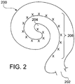
- Fig. 2 illustrates a schematic structure of the human cochlea 200.
- the cochlea 200 is in the shape of a spiral beginning at a base 202 and ending at an apex 204.
- auditory nerve tissue 206 Within the cochlea 200 resides auditory nerve tissue 206.
- the auditory nerve tissue 206 is organized within the cochlea 200 in a tonotopic manner.
- Low frequencies are encoded at the apex 204 of the cochlea 200 while high frequencies are encoded at the base 202.
- Stimulation subsystem 12 is configured to apply stimulation to different locations within the cochlea 200 (e.g., different locations along the auditory nerve tissue 206) to provide a sensation of hearing.
- sound processing subsystem 10 and stimulation subsystem 12 may be configured to operate in accordance with one or more control parameters.
- control parameters may be configured to specify one or more stimulation parameters, operating parameters, and/or any other parameter as may serve a particular application.
- Exemplary control parameters include, but are not limited to, most comfortable current levels ("M levels”), threshold current levels ("T levels”), dynamic range parameters, channel acoustic gain parameters, front and backend dynamic range parameters, current steering parameters, amplitude values, pulse rate values, pulse width values, polarity values, filter characteristics, and/or any other control parameter as may serve a particular application.
- the stimulation sub-system 12 comprises an ICS 14, a lead 16 and the stimulation assembly 18 disposed on the lead 16.
- the stimulation assembly 18 comprises a plurality of "stimulation contacts" 19 for electrical stimulation of the auditory nerve.
- the lead 16 may be inserted within a duct of the cochlea in such a manner that the stimulation contacts 19 are in communication with one or more stimulation sites within the cochlea, i.e. the stimulation contacts 19 are adjacent to, in the general vicinity of, in close proximity to, directly next to, or directly on the respective stimulation site.
- the sound processing sub-system 10 is designed as being located external to the patient; however, in alternative examples, at least one of the components of the sub-system 10 may be implantable.
- the sound processing sub-system 10 comprises a microphone 20 which captures audio signals from ambient sound, a microphone link 22, a sound processor 24 which receives audio signals from the microphone 20 via the link 22, and a headpiece 26 having a coil 28 disposed therein.
- the sound processor 24 is configured to process the captured audio signals in accordance with a selected sound processing strategy to generate appropriate stimulation parameters for controlling the ICS 14 and may include, or be implemented within, a behind-the-ear (BTE) unit or a portable speech processor ("PSP").
- BTE behind-the-ear
- PSP portable speech processor
- the sound processor 24 is configured to transcutaneously transmit data (in particular data representative of one or more stimulation parameters) to the ICS 14 via a wireless transcutaneous communication link 30.
- the headpiece 26 may be affixed to the patient's head and positioned such that the coil 28 is communicatively coupled to the corresponding coil (not shown) included within the ICS 14 in order to establish the link 30.
- the link 30 may include a bidirectional communication link and/or one or more dedicated unidirectional communication links.
- the sound processor 24 and the ICS 14 may be directly connected by wires.
- Fig. 3 a schematic example of a sound processor 24 is shown.
- the audio signals captured by the microphone 20 are amplified in an audio front end circuitry 32, with the amplified audio signal being converted to a digital signal by an analog-to-digital converter 34.
- the resulting digital signal is then subjected to automatic gain control using a suitable automatic gain control (AGC) unit 36.
- AGC automatic gain control
- the digital signal is subjected to a filterbank 38 comprising a plurality of filters F 1 ... Fm (for example, band-pass filters) which are configured to divide the digital signal into m analysis channels 40, each containing a signal representative of a distinct frequency portion of the audio signal sensed by the microphone 20.
- filters F 1 ... Fm for example, band-pass filters
- Fm for example, band-pass filters
- such frequency filtering may be implemented by applying a Discrete Fourier Transform to the audio signal and then divide the resulting frequency bins into the analysis channels 40.
- the signals within each analysis channel 40 are input into an envelope detector 42 in order to determine the amount of energy contained within each of the signals within the analysis channels 40
- the output signals of the envelope detectors 42 are supplied to a mapping module 46 which serves to map the signals in the analysis channels 40 to the stimulation channels S 1 ... S n .
- signal levels may be mapped to amplitude values used to define the electrical stimulation pulses that are applied to the patient by the ICS 14 via M stimulation channels 52.
- each of the m stimulation channels 52 may be associated to one of the stimulation contacts 19 or to a group of the stimulation contacts 19.
- the sound processor 24 further comprises a stimulation strategy module 48 which serves to generate one or more stimulation parameters based on the noise reduced signals and in accordance with a certain stimulation strategy (which may be selected from a plurality of stimulation strategies).
- stimulation strategy module 48 may generate stimulation parameters which direct the ICS 14 to generate and concurrently apply weighted stimulation current via a plurality 52 of the stimulation channels S 1 ... S n in order to effectuate a current steering stimulation strategy.
- the stimulation strategy module 48 may be configured to generate stimulation parameters which direct the ICS 14 to apply electrical stimulation via only a subset N of the stimulation channels 52 in order to effectuate an N-of-M stimulation strategy.
- the sound processor 24 also comprises a multiplexer 50 which serves to serialize the stimulation parameters generated by the stimulation strategy module 48 so that they can be transmitted to the ICS 14 via the communication link 30, i.e. via the coil 28.
- the sound processor 24 may operate in accordance with at least one control parameter, such as the most comfortable listening current levels (MCL), also referred to as “M levels”, threshold current levels (also referred to as “T levels”), dynamic range parameters, channel acoustic gain parameters, front and back end dynamic range parameters, current steering parameters, amplitude values, pulse rate values, pulse width values, polarity values and/or filter characteristics.
- MCL most comfortable listening current levels
- T levels threshold current levels
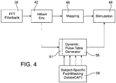
- the stimulation strategy module 48 uses time-interleaved stimulation according to a pulse table provided by a pulse table configuration module 56.
- the pulse table configuration module 56 generates a patient-specific pulse table from patient-specific forward masking patterns obtained from patient specific neural response imaging data provided by a unit 58 to the pulse table configuration module 56.
- the pulse table is re-configured based on the patient's specific forward masking patterns in a manner so as to minimize spatial and/or temporal masking of the stimulation signal according to an optimization algorithm implemented in the pulse table pulse table configuration module 56.
- the patient specific neural response imaging data are eCAP data obtained by reverse telemetry from the electrodes 19 and the ICS 14 via the transcutaneous link 30 (this path is indicated in Fig. 3 at 60).
- eCAP data obtained by reverse telemetry from the electrodes 19 and the ICS 14 via the transcutaneous link 30 (this path is indicated in Fig. 3 at 60).
- a schematic example of such eCAP data in the spatial domain (spreading functions) is shown in Fig. 6 wherein the masking effect of the electrodes #3 (EL3), #10 (EL10) and #15 (EL15) with regard to the other electrodes are shown.
- masking curves typically vary considerably across probe locations. Further, apical portions of the curves may differ from basal portions, i.e. the masking patterns are not symmetric around the probe location.
- FIG. 7 An example of a masking-optimized stimulation strategy is illustrated in Fig. 7 for monopolar stimulation with biphasic pulses.
- the stimulation current at the electrodes number 5 to 8 is shown versus time.
- the left-hand part of Fig. 7 shows a conventional stimulation strategy, wherein the electrodes are simply stimulated one after the other during each stimulation cycle (starting with electrode #8 and terminating with electrode #5). Simulations of the resulting pairwise masking patterns elicited by two successive electrode pairs are shown at the bottom of Fig. 7 (the electrode pairs are distinguished in the representation of the masking pattern by different vertical off-set). It can be seen that the successive electrode stimulation according to the conventional stimulation strategy results in significant pairwise masking of biphasic pulses.
- Fig. 7 shows a corresponding illustration of a stimulation strategy taking into account patient specific forward masking patterns.
- an optimization algorithm is used for finding an electrode stimulation sequence providing for the least spatial forward masking across all biphasic pulses.
- Such optimization process may be enhanced by incorporating information on recovery functions which may also be obtained from patient specific measurements; recovery functions determine the degree of temporal masking of a single pulse.
- recovery functions determine the degree of temporal masking of a single pulse.
- the masking-optimized stimulation sequence results in reduced spatial pairwise masking, which is achieved by the spatial (i.e. tonotopical) separation of successive pulses, as opposed to the conventional stimulation order.
- the pulse table is configured to be static, i.e. the same electrode stimulation order is used in all stimulation cycles. While such approach is computationally less demanding, a still further reduced spatial and/or temporal masking may be achieved by taking into account also the spectral shape of the input signal (the reason is that the strength of masking of a biphasic pulse also depends on the magnitude of the pulse).
- Such a dynamic or time-varying pulse table is updated (or re-configured) as a function of the spectral characteristic of the input audio signal (the spectral characteristic is determined by the signal level of the analysis channel 40 relative to each other as determined by the filter bank 38 and the envelope detector 42). Such update preferably occurs for each new stimulation cycle.
- Figs. 4 and 5 An example of an implementation of such dynamic pulse table is illustrated in Figs. 4 and 5 .
- the output of the (Hilbert) envelope detectors 42 is supplied not only to the mapping module 46 but also to the pulse table configuration module 56, so that the pulse table can be updated for each stimulation cycle according to the present spectral characteristic of the input audio signal as detected by the envelope detector 42.
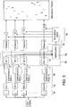
- Fig. 5 is a more detailed representation of the processing scheme of Fig. 4 , wherein 16 analysis channels and 16 stimulation channels are illustrated.
- 16 analysis channels and 16 stimulation channels are illustrated.
- For each stimulation channel/electrode spatio-temporal masking data 58 are supplied, together with the respective output of the envelope detector 42 of the same channel, to a masking function unit 57 which provides for an output to an optimization unit 59 of the pulse table configuration module 56, which output is indicative of the actual masking action of the respective electrode for the present signal level of the same (analysis) channel.
- the optimization algorithm may be a direct search algorithm or an evolutionary algorithm, such as a genetic algorithm. Also, models inspired by signal detection theory may be used.
- the pulse table configuration module 56 may vary the content of the pulse table only in case that the input signal is a voiced / speech signal or a music signal, for which a certain degree of harmonicity is given.
- the sound processor 24 may comprise a classifier (indicated at 61) for determining whether there is a voiced or unvoiced signal by determining the degree of harmonicity of the input audio signal, wherein the pulse table configuration module 56 is controlled according to the output of the classifier 61.
- the pulse table configuration module may use a static pulse table.
- the stimulation strategy applied by the module 48 may be such that the number of selected pulses may vary across the stimulation cycles, i.e. an n-of-m type algorithm may be used. Further, the stimulation strategy may be used in conjunction with current steering.
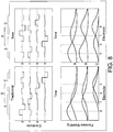
- the present invention is used, as shown in Fig. 7 , for multipolar stimulation, in particular for phased-array stimulation.
- a schematic example of phased-array stimulation is illustrated in Fig. 8 , wherein at the left-hand side a comparative example using a conventional stimulation order (corresponding to the comparative example at the left-hand side of Fig. 7 ) and at the right-hand side an example using a masking-optimized stimulation order (corresponding to the example of the right-hand side of Fig. 7 ) is shown. It can be seen from the simulations shown at the bottom of Fig. 8 that the pairwise masking obtained for the phased-array stimulation is less than that obtained with the monopolar stimulation example shown at the right-hand side of Fig. 7 .
- Fig. 9 is a further illustration of the spatio-temporal masking for three adjacent electrodes E4, E5 and E6 for conventional time-interleaved stimulation order (top), for masking-optimized stimulation order for monopolar biphasic stimulation (center), and for masking-optimized stimulation order for biphasic phased array stimulation (bottom). It can be seen, as in Figs. 7 and 8 , that the masking optimized stimulation order using phased array stimulation provides for the least masking and most focused stimulation, whereas with the conventional ordering, for example, the pulse P5 is entirely masked.
Landscapes
- Health & Medical Sciences (AREA)
- Otolaryngology (AREA)
- Animal Behavior & Ethology (AREA)
- Engineering & Computer Science (AREA)
- Biomedical Technology (AREA)
- Nuclear Medicine, Radiotherapy & Molecular Imaging (AREA)
- Radiology & Medical Imaging (AREA)
- Life Sciences & Earth Sciences (AREA)
- General Health & Medical Sciences (AREA)
- Public Health (AREA)
- Veterinary Medicine (AREA)
- Heart & Thoracic Surgery (AREA)
- Cardiology (AREA)
- Electrotherapy Devices (AREA)
Claims (15)
- Système de stimulation électrique d'une cochlée (200) d'un patient, le système comprenant
un moyen (20) pour fournir un signal audio d'entrée ;
une unité de traitement du son (24) pour générer un signal de stimulation électrique à partir du signal audio d'entrée ; et
un agencement d'électrodes (19) d'implant cochléaire comprenant une pluralité de canaux de stimulation pour stimuler la cochlée en fonction du signal de stimulation électrique ;
l'unité de traitement du son comprenantune unité banc de filtres (38) pour subdiviser le signal audio d'entrée en une pluralité de canaux d'analyse, contenant chacun un signal en domaine fréquentiel représentant une partie fréquentielle du signal audio,une unité de niveau de signal (42) pour établir un niveau de signal pour chaque canal d'analyse par analyse du signal en domaine fréquentiel respectif,une unité de signal de stimulation (46, 48) pour générer un signal de stimulation électrique pour chaque canal de stimulation en fonction du niveau de signal respectif,une unité de commande d'ordre de stimulation (48, 56) pour commander l'ordre temporel de stimulation des canaux de stimulation en fonction d'une table d'impulsions propre au patient appelée à être générée par un module de configuration de table d'impulsions (56) à partir de patrons de masquage proactif propres au patient obtenus à partir de données d'imagerie de réponse neuronale propres au patient de manière à minimiser le masquage spatial et/ou temporel du signal de stimulation en fonction d'un algorithme d'optimisation,le système étant caractérisé en ce quel'unité de signal de stimulation (46, 48) sert à générer des impulsions multipolaires. - Système selon la revendication 1, dans lequel le module de configuration de table d'impulsions (56) sert à fournir une table d'impulsions statique appelée à être configurée préalablement à la stimulation.
- Système selon la revendication 1, dans lequel le module de configuration de table d'impulsions (56) sert à fournir une table d'impulsions dynamique qui est mise à jour en fonction de la caractéristique spectrale du signal audio d'entrée, laquelle caractéristique spectrale est établie par les niveaux de signal des canaux d'analyse en relation les uns avec les autres.
- Système selon la revendication 3, dans lequel le module de configuration de table d'impulsions (56) sert à mettre à jour la table d'impulsions dynamique pour chaque cycle de stimulation.
- Système selon l'une des revendications 3 et 4, dans lequel l'unité de traitement du son (24) comprend une unité de classification (61) pour établir si le signal audio d'entrée est un signal voisé ou un signal non voisé, et dans lequel le module de configuration de table d'impulsions (56) est commandé par l'unité de classification de telle sorte que le module de configuration de table d'impulsions fournisse une table d'impulsions statique si un signal non voisé est établi et une table d'impulsions dynamique mise à jour en fonction de la caractéristique spectrale du signal audio d'entrée si un signal voisé est établi.
- Système selon la revendication 5, dans lequel l'unité de classification (61) sert à établir le degré d'harmonicité du signal audio d'entrée dans le but d'établir si le signal audio d'entrée est un signal voisé ou un signal non voisé.
- Système selon l'une des revendications précédentes, dans lequel les données d'imagerie de réponse neuronale propres au patient sont des données eCAP.
- Système selon l'une des revendications précédentes, dans lequel le module de configuration de table d'impulsions (56) sert à utiliser des données sur des fonctions de récupération mesurées propres au patient.
- Système selon l'une des revendications précédentes, dans lequel l'algorithme d'optimisation est un algorithme par recherche directe ou un algorithme évolutionnaire.
- Système selon la revendication 9, dans lequel l'algorithme d'optimisation est un algorithme génétique.
- Système selon l'une des revendications précédentes, dans lequel l'algorithme d'optimisation utilise un modèle basé sur une théorie de détection de signal.
- Système selon l'une des revendications précédentes, dans lequel l'unité de stimulation de signal (46, 48) sert à générer des impulsions biphasiques.
- Système selon la revendication 1, dans lequel l'unité de signal de stimulation (46, 48) sert à générer des impulsions de réseau à commande de phase, et dans lequel l'unité de signal de stimulation (46, 48) sert à pondérer les courants de compensation en fonction de mesures d'impédance basées sur une imagerie de réponse neuronale.
- Système selon l'une des revendications précédentes, dans lequel l'unité de signal de stimulation (46, 48) sert à générer un signal de stimulation par routage de courant.
- Système selon l'une des revendications précédentes, dans lequel l'unité de signal de stimulation (46, 48) sert à générer le signal de stimulation de manière à ce que le nombre d'impulsions sélectionnées soit variable sur l'ensemble des cycles de stimulation.
Applications Claiming Priority (1)
| Application Number | Priority Date | Filing Date | Title |
|---|---|---|---|
| PCT/EP2013/054462 WO2014135203A1 (fr) | 2013-03-06 | 2013-03-06 | Procédé et système de stimulation électrique de la cochlée |
Publications (2)
| Publication Number | Publication Date |
|---|---|
| EP2964319A1 EP2964319A1 (fr) | 2016-01-13 |
| EP2964319B1 true EP2964319B1 (fr) | 2016-12-21 |
Family
ID=47997375
Family Applications (1)
| Application Number | Title | Priority Date | Filing Date |
|---|---|---|---|
| EP13712164.6A Not-in-force EP2964319B1 (fr) | 2013-03-06 | 2013-03-06 | Système de stimulation électrique de la cochlée |
Country Status (3)
| Country | Link |
|---|---|
| US (1) | US9770589B2 (fr) |
| EP (1) | EP2964319B1 (fr) |
| WO (1) | WO2014135203A1 (fr) |
Cited By (1)
| Publication number | Priority date | Publication date | Assignee | Title |
|---|---|---|---|---|
| EP3760278B1 (fr) * | 2019-07-05 | 2022-07-20 | Oticon Medical A/S | Système d'implant cochléaire avec schéma de sélection d'électrode amélioré |
Families Citing this family (9)
| Publication number | Priority date | Publication date | Assignee | Title |
|---|---|---|---|---|
| US10814126B2 (en) | 2015-05-22 | 2020-10-27 | Cochlear Limited | Dynamic current steering |
| US9776001B2 (en) | 2015-06-11 | 2017-10-03 | Med-El Elektromedizinische Geraete Gmbh | Interaural coherence based cochlear stimulation using adapted envelope processing |
| US9808624B2 (en) | 2015-06-11 | 2017-11-07 | Med-El Elektromedizinische Geraete Gmbh | Interaural coherence based cochlear stimulation using adapted fine structure processing |
| CN107708797B (zh) * | 2015-06-11 | 2021-01-19 | Med-El电气医疗器械有限公司 | 切换听力植入物编码策略 |
| US10743114B2 (en) | 2016-11-22 | 2020-08-11 | Cochlear Limited | Dynamic stimulus resolution adaption |
| US10512775B2 (en) * | 2017-08-30 | 2019-12-24 | Cochlear Limited | Noise reduction for implantable hearing prostheses |
| US12447341B2 (en) * | 2018-12-28 | 2025-10-21 | Advanced Bionics Ag | Evoked response-based systems and methods for determining electrode positioning within a cochlea |
| EP3760279B1 (fr) | 2019-07-05 | 2024-08-28 | Cochlear Limited | Système d'implant cochléaire comprenant un modèle amélioré d'interférences inter-électrodes |
| EP3967364A1 (fr) * | 2020-09-14 | 2022-03-16 | Oticon Medical A/S | Codage multidimensionnel d'impulsions de stimulation |
Family Cites Families (8)
| Publication number | Priority date | Publication date | Assignee | Title |
|---|---|---|---|---|
| DE60032490T2 (de) | 1999-03-03 | 2007-09-27 | Cochlear Ltd., Lane Cove | Gerät zur optimierung der funktion eines kochlearen implantates |
| DE60107062T2 (de) * | 2000-03-31 | 2005-11-24 | Advanced Bionics Corp., Sylmar | Vollständig implantierbare cochlea-microprothese mit einer vielzahl von kontakten |
| US8285382B2 (en) * | 2000-08-21 | 2012-10-09 | Cochlear Limited | Determining stimulation signals for neural stimulation |
| US7206640B1 (en) * | 2002-11-08 | 2007-04-17 | Advanced Bionics Corporation | Method and system for generating a cochlear implant program using multi-electrode stimulation to elicit the electrically-evoked compound action potential |
| US7421298B2 (en) * | 2004-09-07 | 2008-09-02 | Cochlear Limited | Multiple channel-electrode mapping |
| US8346368B2 (en) | 2008-05-30 | 2013-01-01 | Cochlear Limited | Sound processing method and system |
| US8422706B2 (en) | 2009-09-11 | 2013-04-16 | Advanced Bionics, Llc | Methods and systems for reducing an effect of ambient noise within an auditory prosthesis system |
| US9031661B2 (en) | 2010-05-18 | 2015-05-12 | Cochlear Limited | Multi-electrode channel configurations for a hearing prosthesis |
-
2013
- 2013-03-06 WO PCT/EP2013/054462 patent/WO2014135203A1/fr not_active Ceased
- 2013-03-06 EP EP13712164.6A patent/EP2964319B1/fr not_active Not-in-force
- 2013-03-06 US US14/773,314 patent/US9770589B2/en not_active Expired - Fee Related
Cited By (1)
| Publication number | Priority date | Publication date | Assignee | Title |
|---|---|---|---|---|
| EP3760278B1 (fr) * | 2019-07-05 | 2022-07-20 | Oticon Medical A/S | Système d'implant cochléaire avec schéma de sélection d'électrode amélioré |
Also Published As
| Publication number | Publication date |
|---|---|
| US20160015974A1 (en) | 2016-01-21 |
| EP2964319A1 (fr) | 2016-01-13 |
| US9770589B2 (en) | 2017-09-26 |
| WO2014135203A1 (fr) | 2014-09-12 |
Similar Documents
| Publication | Publication Date | Title |
|---|---|---|
| EP2964319B1 (fr) | Système de stimulation électrique de la cochlée | |
| KR101897309B1 (ko) | 이식된 보철물을 사용하여 신경 자극을 검출하는 시스템들 및 방법들 | |
| US9744358B2 (en) | System and method for neural cochlea stimulation | |
| EP3337555B1 (fr) | Système d'implant cochléaire | |
| EP2964325B1 (fr) | Système de stimulation de cochlée | |
| EP2482923B1 (fr) | Systèmes pour représenter différentes composantes spectrales d'un signal audio présenté à un patient ayant un implant cochléaire | |
| EP3030313B1 (fr) | Système comprenant un stimulateur cochléaire et un deuxième stimulateur auditif | |
| US8751006B2 (en) | Channel-specific adjustment of sound processing strategies based on electrode impedance | |
| WO2015136505A1 (fr) | Gestion de stimulation | |
| US9227063B2 (en) | Methods and systems for lowering a pitch sensation as perceived by a cochlear implant patient | |
| WO2010009010A1 (fr) | Optimisation à base de tonalité de sensation sonore pour un patient muni d'un implant cochléaire | |
| CN103533986A (zh) | 具有通道交互补偿的同时刺激的最佳模型常数 | |
| US20160199641A1 (en) | Device and method for neural cochlea stimulation | |
| WO2021053045A1 (fr) | Adaptation d'un implant cochléaire sur la base de l'état neuronal | |
| US8768476B2 (en) | Methods and systems of compensating for a disabled electrode | |
| EP3033142A1 (fr) | Systèmes de focalisation dépendant de la fréquence et procédés utilisables dans un système d'implant cochléaire | |
| Rubinstein | Cochlear implant coding strategies and device programming | |
| EP3492137A1 (fr) | Prothèse auditive implantable faisant appel à une impulsion de stimulation |
Legal Events
| Date | Code | Title | Description |
|---|---|---|---|
| PUAI | Public reference made under article 153(3) epc to a published international application that has entered the european phase |
Free format text: ORIGINAL CODE: 0009012 |
|
| 17P | Request for examination filed |
Effective date: 20150914 |
|
| AK | Designated contracting states |
Kind code of ref document: A1 Designated state(s): AL AT BE BG CH CY CZ DE DK EE ES FI FR GB GR HR HU IE IS IT LI LT LU LV MC MK MT NL NO PL PT RO RS SE SI SK SM TR |
|
| AX | Request for extension of the european patent |
Extension state: BA ME |
|
| RIN1 | Information on inventor provided before grant (corrected) |
Inventor name: MILCZYNSKI, MATTHIAS |
|
| DAX | Request for extension of the european patent (deleted) | ||
| GRAP | Despatch of communication of intention to grant a patent |
Free format text: ORIGINAL CODE: EPIDOSNIGR1 |
|
| INTG | Intention to grant announced |
Effective date: 20160805 |
|
| GRAS | Grant fee paid |
Free format text: ORIGINAL CODE: EPIDOSNIGR3 |
|
| GRAA | (expected) grant |
Free format text: ORIGINAL CODE: 0009210 |
|
| AK | Designated contracting states |
Kind code of ref document: B1 Designated state(s): AL AT BE BG CH CY CZ DE DK EE ES FI FR GB GR HR HU IE IS IT LI LT LU LV MC MK MT NL NO PL PT RO RS SE SI SK SM TR |
|
| REG | Reference to a national code |
Ref country code: GB Ref legal event code: FG4D |
|
| REG | Reference to a national code |
Ref country code: CH Ref legal event code: EP |
|
| REG | Reference to a national code |
Ref country code: IE Ref legal event code: FG4D |
|
| REG | Reference to a national code |
Ref country code: AT Ref legal event code: REF Ref document number: 854959 Country of ref document: AT Kind code of ref document: T Effective date: 20170115 |
|
| REG | Reference to a national code |
Ref country code: DE Ref legal event code: R096 Ref document number: 602013015572 Country of ref document: DE |
|
| PG25 | Lapsed in a contracting state [announced via postgrant information from national office to epo] |
Ref country code: LV Free format text: LAPSE BECAUSE OF FAILURE TO SUBMIT A TRANSLATION OF THE DESCRIPTION OR TO PAY THE FEE WITHIN THE PRESCRIBED TIME-LIMIT Effective date: 20161221 |
|
| REG | Reference to a national code |
Ref country code: LT Ref legal event code: MG4D |
|
| REG | Reference to a national code |
Ref country code: NL Ref legal event code: MP Effective date: 20161221 |
|
| PG25 | Lapsed in a contracting state [announced via postgrant information from national office to epo] |
Ref country code: SE Free format text: LAPSE BECAUSE OF FAILURE TO SUBMIT A TRANSLATION OF THE DESCRIPTION OR TO PAY THE FEE WITHIN THE PRESCRIBED TIME-LIMIT Effective date: 20161221 Ref country code: GR Free format text: LAPSE BECAUSE OF FAILURE TO SUBMIT A TRANSLATION OF THE DESCRIPTION OR TO PAY THE FEE WITHIN THE PRESCRIBED TIME-LIMIT Effective date: 20170322 Ref country code: NO Free format text: LAPSE BECAUSE OF FAILURE TO SUBMIT A TRANSLATION OF THE DESCRIPTION OR TO PAY THE FEE WITHIN THE PRESCRIBED TIME-LIMIT Effective date: 20170321 Ref country code: LT Free format text: LAPSE BECAUSE OF FAILURE TO SUBMIT A TRANSLATION OF THE DESCRIPTION OR TO PAY THE FEE WITHIN THE PRESCRIBED TIME-LIMIT Effective date: 20161221 |
|
| REG | Reference to a national code |
Ref country code: AT Ref legal event code: MK05 Ref document number: 854959 Country of ref document: AT Kind code of ref document: T Effective date: 20161221 |
|
| PG25 | Lapsed in a contracting state [announced via postgrant information from national office to epo] |
Ref country code: HR Free format text: LAPSE BECAUSE OF FAILURE TO SUBMIT A TRANSLATION OF THE DESCRIPTION OR TO PAY THE FEE WITHIN THE PRESCRIBED TIME-LIMIT Effective date: 20161221 Ref country code: RS Free format text: LAPSE BECAUSE OF FAILURE TO SUBMIT A TRANSLATION OF THE DESCRIPTION OR TO PAY THE FEE WITHIN THE PRESCRIBED TIME-LIMIT Effective date: 20161221 Ref country code: FI Free format text: LAPSE BECAUSE OF FAILURE TO SUBMIT A TRANSLATION OF THE DESCRIPTION OR TO PAY THE FEE WITHIN THE PRESCRIBED TIME-LIMIT Effective date: 20161221 |
|
| PG25 | Lapsed in a contracting state [announced via postgrant information from national office to epo] |
Ref country code: NL Free format text: LAPSE BECAUSE OF FAILURE TO SUBMIT A TRANSLATION OF THE DESCRIPTION OR TO PAY THE FEE WITHIN THE PRESCRIBED TIME-LIMIT Effective date: 20161221 |
|
| PG25 | Lapsed in a contracting state [announced via postgrant information from national office to epo] |
Ref country code: EE Free format text: LAPSE BECAUSE OF FAILURE TO SUBMIT A TRANSLATION OF THE DESCRIPTION OR TO PAY THE FEE WITHIN THE PRESCRIBED TIME-LIMIT Effective date: 20161221 Ref country code: IS Free format text: LAPSE BECAUSE OF FAILURE TO SUBMIT A TRANSLATION OF THE DESCRIPTION OR TO PAY THE FEE WITHIN THE PRESCRIBED TIME-LIMIT Effective date: 20170421 Ref country code: SK Free format text: LAPSE BECAUSE OF FAILURE TO SUBMIT A TRANSLATION OF THE DESCRIPTION OR TO PAY THE FEE WITHIN THE PRESCRIBED TIME-LIMIT Effective date: 20161221 Ref country code: CZ Free format text: LAPSE BECAUSE OF FAILURE TO SUBMIT A TRANSLATION OF THE DESCRIPTION OR TO PAY THE FEE WITHIN THE PRESCRIBED TIME-LIMIT Effective date: 20161221 Ref country code: RO Free format text: LAPSE BECAUSE OF FAILURE TO SUBMIT A TRANSLATION OF THE DESCRIPTION OR TO PAY THE FEE WITHIN THE PRESCRIBED TIME-LIMIT Effective date: 20161221 |
|
| PG25 | Lapsed in a contracting state [announced via postgrant information from national office to epo] |
Ref country code: AT Free format text: LAPSE BECAUSE OF FAILURE TO SUBMIT A TRANSLATION OF THE DESCRIPTION OR TO PAY THE FEE WITHIN THE PRESCRIBED TIME-LIMIT Effective date: 20161221 Ref country code: BG Free format text: LAPSE BECAUSE OF FAILURE TO SUBMIT A TRANSLATION OF THE DESCRIPTION OR TO PAY THE FEE WITHIN THE PRESCRIBED TIME-LIMIT Effective date: 20170321 Ref country code: ES Free format text: LAPSE BECAUSE OF FAILURE TO SUBMIT A TRANSLATION OF THE DESCRIPTION OR TO PAY THE FEE WITHIN THE PRESCRIBED TIME-LIMIT Effective date: 20161221 Ref country code: PL Free format text: LAPSE BECAUSE OF FAILURE TO SUBMIT A TRANSLATION OF THE DESCRIPTION OR TO PAY THE FEE WITHIN THE PRESCRIBED TIME-LIMIT Effective date: 20161221 Ref country code: PT Free format text: LAPSE BECAUSE OF FAILURE TO SUBMIT A TRANSLATION OF THE DESCRIPTION OR TO PAY THE FEE WITHIN THE PRESCRIBED TIME-LIMIT Effective date: 20170421 Ref country code: SM Free format text: LAPSE BECAUSE OF FAILURE TO SUBMIT A TRANSLATION OF THE DESCRIPTION OR TO PAY THE FEE WITHIN THE PRESCRIBED TIME-LIMIT Effective date: 20161221 Ref country code: BE Free format text: LAPSE BECAUSE OF FAILURE TO SUBMIT A TRANSLATION OF THE DESCRIPTION OR TO PAY THE FEE WITHIN THE PRESCRIBED TIME-LIMIT Effective date: 20161221 Ref country code: IT Free format text: LAPSE BECAUSE OF FAILURE TO SUBMIT A TRANSLATION OF THE DESCRIPTION OR TO PAY THE FEE WITHIN THE PRESCRIBED TIME-LIMIT Effective date: 20161221 |
|
| REG | Reference to a national code |
Ref country code: DE Ref legal event code: R097 Ref document number: 602013015572 Country of ref document: DE |
|
| PLBE | No opposition filed within time limit |
Free format text: ORIGINAL CODE: 0009261 |
|
| STAA | Information on the status of an ep patent application or granted ep patent |
Free format text: STATUS: NO OPPOSITION FILED WITHIN TIME LIMIT |
|
| REG | Reference to a national code |
Ref country code: CH Ref legal event code: PL |
|
| 26N | No opposition filed |
Effective date: 20170922 |
|
| GBPC | Gb: european patent ceased through non-payment of renewal fee |
Effective date: 20170321 |
|
| PG25 | Lapsed in a contracting state [announced via postgrant information from national office to epo] |
Ref country code: MC Free format text: LAPSE BECAUSE OF FAILURE TO SUBMIT A TRANSLATION OF THE DESCRIPTION OR TO PAY THE FEE WITHIN THE PRESCRIBED TIME-LIMIT Effective date: 20161221 Ref country code: DK Free format text: LAPSE BECAUSE OF FAILURE TO SUBMIT A TRANSLATION OF THE DESCRIPTION OR TO PAY THE FEE WITHIN THE PRESCRIBED TIME-LIMIT Effective date: 20161221 |
|
| REG | Reference to a national code |
Ref country code: IE Ref legal event code: MM4A |
|
| REG | Reference to a national code |
Ref country code: FR Ref legal event code: ST Effective date: 20171130 |
|
| PG25 | Lapsed in a contracting state [announced via postgrant information from national office to epo] |
Ref country code: FR Free format text: LAPSE BECAUSE OF NON-PAYMENT OF DUE FEES Effective date: 20170331 Ref country code: LU Free format text: LAPSE BECAUSE OF NON-PAYMENT OF DUE FEES Effective date: 20170306 |
|
| PG25 | Lapsed in a contracting state [announced via postgrant information from national office to epo] |
Ref country code: LI Free format text: LAPSE BECAUSE OF NON-PAYMENT OF DUE FEES Effective date: 20170331 Ref country code: CH Free format text: LAPSE BECAUSE OF NON-PAYMENT OF DUE FEES Effective date: 20170331 Ref country code: IE Free format text: LAPSE BECAUSE OF NON-PAYMENT OF DUE FEES Effective date: 20170306 Ref country code: SI Free format text: LAPSE BECAUSE OF FAILURE TO SUBMIT A TRANSLATION OF THE DESCRIPTION OR TO PAY THE FEE WITHIN THE PRESCRIBED TIME-LIMIT Effective date: 20161221 Ref country code: GB Free format text: LAPSE BECAUSE OF NON-PAYMENT OF DUE FEES Effective date: 20170321 |
|
| PG25 | Lapsed in a contracting state [announced via postgrant information from national office to epo] |
Ref country code: MT Free format text: LAPSE BECAUSE OF NON-PAYMENT OF DUE FEES Effective date: 20170306 |
|
| PG25 | Lapsed in a contracting state [announced via postgrant information from national office to epo] |
Ref country code: HU Free format text: LAPSE BECAUSE OF FAILURE TO SUBMIT A TRANSLATION OF THE DESCRIPTION OR TO PAY THE FEE WITHIN THE PRESCRIBED TIME-LIMIT; INVALID AB INITIO Effective date: 20130306 |
|
| PG25 | Lapsed in a contracting state [announced via postgrant information from national office to epo] |
Ref country code: CY Free format text: LAPSE BECAUSE OF FAILURE TO SUBMIT A TRANSLATION OF THE DESCRIPTION OR TO PAY THE FEE WITHIN THE PRESCRIBED TIME-LIMIT Effective date: 20161221 |
|
| PG25 | Lapsed in a contracting state [announced via postgrant information from national office to epo] |
Ref country code: MK Free format text: LAPSE BECAUSE OF FAILURE TO SUBMIT A TRANSLATION OF THE DESCRIPTION OR TO PAY THE FEE WITHIN THE PRESCRIBED TIME-LIMIT Effective date: 20161221 |
|
| PG25 | Lapsed in a contracting state [announced via postgrant information from national office to epo] |
Ref country code: TR Free format text: LAPSE BECAUSE OF FAILURE TO SUBMIT A TRANSLATION OF THE DESCRIPTION OR TO PAY THE FEE WITHIN THE PRESCRIBED TIME-LIMIT Effective date: 20161221 |
|
| PG25 | Lapsed in a contracting state [announced via postgrant information from national office to epo] |
Ref country code: AL Free format text: LAPSE BECAUSE OF FAILURE TO SUBMIT A TRANSLATION OF THE DESCRIPTION OR TO PAY THE FEE WITHIN THE PRESCRIBED TIME-LIMIT Effective date: 20161221 |
|
| PGFP | Annual fee paid to national office [announced via postgrant information from national office to epo] |
Ref country code: DE Payment date: 20240327 Year of fee payment: 12 |
|
| P01 | Opt-out of the competence of the unified patent court (upc) registered |
Free format text: CASE NUMBER: UPC_APP_427232/2023 Effective date: 20230525 |
|
| REG | Reference to a national code |
Ref country code: DE Ref legal event code: R119 Ref document number: 602013015572 Country of ref document: DE |
|
| PG25 | Lapsed in a contracting state [announced via postgrant information from national office to epo] |
Ref country code: DE Free format text: LAPSE BECAUSE OF NON-PAYMENT OF DUE FEES Effective date: 20251001 |