EP2964417B1 - Verfahren zum einbringen von durchbrechungen in ein substrat - Google Patents
Verfahren zum einbringen von durchbrechungen in ein substrat Download PDFInfo
- Publication number
- EP2964417B1 EP2964417B1 EP14726069.9A EP14726069A EP2964417B1 EP 2964417 B1 EP2964417 B1 EP 2964417B1 EP 14726069 A EP14726069 A EP 14726069A EP 2964417 B1 EP2964417 B1 EP 2964417B1
- Authority
- EP
- European Patent Office
- Prior art keywords
- substrate
- laser radiation
- laser
- intensity
- focal
- Prior art date
- Legal status (The legal status is an assumption and is not a legal conclusion. Google has not performed a legal analysis and makes no representation as to the accuracy of the status listed.)
- Active
Links
Images



Classifications
-
- B—PERFORMING OPERATIONS; TRANSPORTING
- B23—MACHINE TOOLS; METAL-WORKING NOT OTHERWISE PROVIDED FOR
- B23K—SOLDERING OR UNSOLDERING; WELDING; CLADDING OR PLATING BY SOLDERING OR WELDING; CUTTING BY APPLYING HEAT LOCALLY, e.g. FLAME CUTTING; WORKING BY LASER BEAM
- B23K26/00—Working by laser beam, e.g. welding, cutting or boring
- B23K26/36—Removing material
- B23K26/38—Removing material by boring or cutting
- B23K26/382—Removing material by boring or cutting by boring
-
- B—PERFORMING OPERATIONS; TRANSPORTING
- B23—MACHINE TOOLS; METAL-WORKING NOT OTHERWISE PROVIDED FOR
- B23K—SOLDERING OR UNSOLDERING; WELDING; CLADDING OR PLATING BY SOLDERING OR WELDING; CUTTING BY APPLYING HEAT LOCALLY, e.g. FLAME CUTTING; WORKING BY LASER BEAM
- B23K26/00—Working by laser beam, e.g. welding, cutting or boring
- B23K26/18—Working by laser beam, e.g. welding, cutting or boring using absorbing layers on the workpiece, e.g. for marking or protecting purposes
-
- B—PERFORMING OPERATIONS; TRANSPORTING
- B23—MACHINE TOOLS; METAL-WORKING NOT OTHERWISE PROVIDED FOR
- B23K—SOLDERING OR UNSOLDERING; WELDING; CLADDING OR PLATING BY SOLDERING OR WELDING; CUTTING BY APPLYING HEAT LOCALLY, e.g. FLAME CUTTING; WORKING BY LASER BEAM
- B23K26/00—Working by laser beam, e.g. welding, cutting or boring
- B23K26/0006—Working by laser beam, e.g. welding, cutting or boring taking account of the properties of the material involved
-
- B—PERFORMING OPERATIONS; TRANSPORTING
- B23—MACHINE TOOLS; METAL-WORKING NOT OTHERWISE PROVIDED FOR
- B23K—SOLDERING OR UNSOLDERING; WELDING; CLADDING OR PLATING BY SOLDERING OR WELDING; CUTTING BY APPLYING HEAT LOCALLY, e.g. FLAME CUTTING; WORKING BY LASER BEAM
- B23K26/00—Working by laser beam, e.g. welding, cutting or boring
- B23K26/02—Positioning or observing the workpiece, e.g. with respect to the point of impact; Aligning, aiming or focusing the laser beam
- B23K26/06—Shaping the laser beam, e.g. by masks or multi-focusing
- B23K26/062—Shaping the laser beam, e.g. by masks or multi-focusing by direct control of the laser beam
- B23K26/0622—Shaping the laser beam, e.g. by masks or multi-focusing by direct control of the laser beam by shaping pulses
- B23K26/0624—Shaping the laser beam, e.g. by masks or multi-focusing by direct control of the laser beam by shaping pulses using ultrashort pulses, i.e. pulses of 1 ns or less
-
- B—PERFORMING OPERATIONS; TRANSPORTING
- B23—MACHINE TOOLS; METAL-WORKING NOT OTHERWISE PROVIDED FOR
- B23K—SOLDERING OR UNSOLDERING; WELDING; CLADDING OR PLATING BY SOLDERING OR WELDING; CUTTING BY APPLYING HEAT LOCALLY, e.g. FLAME CUTTING; WORKING BY LASER BEAM
- B23K26/00—Working by laser beam, e.g. welding, cutting or boring
- B23K26/02—Positioning or observing the workpiece, e.g. with respect to the point of impact; Aligning, aiming or focusing the laser beam
- B23K26/06—Shaping the laser beam, e.g. by masks or multi-focusing
- B23K26/064—Shaping the laser beam, e.g. by masks or multi-focusing by means of optical elements, e.g. lenses, mirrors or prisms
-
- B—PERFORMING OPERATIONS; TRANSPORTING
- B23—MACHINE TOOLS; METAL-WORKING NOT OTHERWISE PROVIDED FOR
- B23K—SOLDERING OR UNSOLDERING; WELDING; CLADDING OR PLATING BY SOLDERING OR WELDING; CUTTING BY APPLYING HEAT LOCALLY, e.g. FLAME CUTTING; WORKING BY LASER BEAM
- B23K26/00—Working by laser beam, e.g. welding, cutting or boring
- B23K26/36—Removing material
- B23K26/40—Removing material taking account of the properties of the material involved
- B23K26/402—Removing material taking account of the properties of the material involved involving non-metallic material, e.g. isolators
-
- B—PERFORMING OPERATIONS; TRANSPORTING
- B23—MACHINE TOOLS; METAL-WORKING NOT OTHERWISE PROVIDED FOR
- B23K—SOLDERING OR UNSOLDERING; WELDING; CLADDING OR PLATING BY SOLDERING OR WELDING; CUTTING BY APPLYING HEAT LOCALLY, e.g. FLAME CUTTING; WORKING BY LASER BEAM
- B23K26/00—Working by laser beam, e.g. welding, cutting or boring
- B23K26/50—Working by transmitting the laser beam through or within the workpiece
-
- B—PERFORMING OPERATIONS; TRANSPORTING
- B23—MACHINE TOOLS; METAL-WORKING NOT OTHERWISE PROVIDED FOR
- B23K—SOLDERING OR UNSOLDERING; WELDING; CLADDING OR PLATING BY SOLDERING OR WELDING; CUTTING BY APPLYING HEAT LOCALLY, e.g. FLAME CUTTING; WORKING BY LASER BEAM
- B23K26/00—Working by laser beam, e.g. welding, cutting or boring
- B23K26/50—Working by transmitting the laser beam through or within the workpiece
- B23K26/53—Working by transmitting the laser beam through or within the workpiece for modifying or reforming the material inside the workpiece, e.g. for producing break initiation cracks
-
- H—ELECTRICITY
- H10—SEMICONDUCTOR DEVICES; ELECTRIC SOLID-STATE DEVICES NOT OTHERWISE PROVIDED FOR
- H10W—GENERIC PACKAGES, INTERCONNECTIONS, CONNECTORS OR OTHER CONSTRUCTIONAL DETAILS OF DEVICES COVERED BY CLASS H10
- H10W70/00—Package substrates; Interposers; Redistribution layers [RDL]
- H10W70/01—Manufacture or treatment
- H10W70/05—Manufacture or treatment of insulating or insulated package substrates, or of interposers, or of redistribution layers
- H10W70/095—Manufacture or treatment of insulating or insulated package substrates, or of interposers, or of redistribution layers of vias therein
-
- B—PERFORMING OPERATIONS; TRANSPORTING
- B23—MACHINE TOOLS; METAL-WORKING NOT OTHERWISE PROVIDED FOR
- B23K—SOLDERING OR UNSOLDERING; WELDING; CLADDING OR PLATING BY SOLDERING OR WELDING; CUTTING BY APPLYING HEAT LOCALLY, e.g. FLAME CUTTING; WORKING BY LASER BEAM
- B23K2101/00—Articles made by soldering, welding or cutting
- B23K2101/36—Electric or electronic devices
- B23K2101/40—Semiconductor devices
-
- B—PERFORMING OPERATIONS; TRANSPORTING
- B23—MACHINE TOOLS; METAL-WORKING NOT OTHERWISE PROVIDED FOR
- B23K—SOLDERING OR UNSOLDERING; WELDING; CLADDING OR PLATING BY SOLDERING OR WELDING; CUTTING BY APPLYING HEAT LOCALLY, e.g. FLAME CUTTING; WORKING BY LASER BEAM
- B23K2103/00—Materials to be soldered, welded or cut
- B23K2103/50—Inorganic materials other than metals or composite materials
-
- B—PERFORMING OPERATIONS; TRANSPORTING
- B23—MACHINE TOOLS; METAL-WORKING NOT OTHERWISE PROVIDED FOR
- B23K—SOLDERING OR UNSOLDERING; WELDING; CLADDING OR PLATING BY SOLDERING OR WELDING; CUTTING BY APPLYING HEAT LOCALLY, e.g. FLAME CUTTING; WORKING BY LASER BEAM
- B23K2103/00—Materials to be soldered, welded or cut
- B23K2103/50—Inorganic materials other than metals or composite materials
- B23K2103/54—Glass
-
- B—PERFORMING OPERATIONS; TRANSPORTING
- B23—MACHINE TOOLS; METAL-WORKING NOT OTHERWISE PROVIDED FOR
- B23K—SOLDERING OR UNSOLDERING; WELDING; CLADDING OR PLATING BY SOLDERING OR WELDING; CUTTING BY APPLYING HEAT LOCALLY, e.g. FLAME CUTTING; WORKING BY LASER BEAM
- B23K2103/00—Materials to be soldered, welded or cut
- B23K2103/50—Inorganic materials other than metals or composite materials
- B23K2103/56—Inorganic materials other than metals or composite materials being semiconducting
-
- H—ELECTRICITY
- H10—SEMICONDUCTOR DEVICES; ELECTRIC SOLID-STATE DEVICES NOT OTHERWISE PROVIDED FOR
- H10W—GENERIC PACKAGES, INTERCONNECTIONS, CONNECTORS OR OTHER CONSTRUCTIONAL DETAILS OF DEVICES COVERED BY CLASS H10
- H10W70/00—Package substrates; Interposers; Redistribution layers [RDL]
- H10W70/60—Insulating or insulated package substrates; Interposers; Redistribution layers
- H10W70/62—Insulating or insulated package substrates; Interposers; Redistribution layers characterised by their interconnections
- H10W70/63—Vias, e.g. via plugs
- H10W70/635—Through-vias
-
- H—ELECTRICITY
- H10—SEMICONDUCTOR DEVICES; ELECTRIC SOLID-STATE DEVICES NOT OTHERWISE PROVIDED FOR
- H10W—GENERIC PACKAGES, INTERCONNECTIONS, CONNECTORS OR OTHER CONSTRUCTIONAL DETAILS OF DEVICES COVERED BY CLASS H10
- H10W70/00—Package substrates; Interposers; Redistribution layers [RDL]
- H10W70/60—Insulating or insulated package substrates; Interposers; Redistribution layers
- H10W70/67—Insulating or insulated package substrates; Interposers; Redistribution layers characterised by their insulating layers or insulating parts
- H10W70/69—Insulating materials thereof
- H10W70/692—Ceramics or glasses
-
- H—ELECTRICITY
- H10—SEMICONDUCTOR DEVICES; ELECTRIC SOLID-STATE DEVICES NOT OTHERWISE PROVIDED FOR
- H10W—GENERIC PACKAGES, INTERCONNECTIONS, CONNECTORS OR OTHER CONSTRUCTIONAL DETAILS OF DEVICES COVERED BY CLASS H10
- H10W70/00—Package substrates; Interposers; Redistribution layers [RDL]
- H10W70/60—Insulating or insulated package substrates; Interposers; Redistribution layers
- H10W70/67—Insulating or insulated package substrates; Interposers; Redistribution layers characterised by their insulating layers or insulating parts
- H10W70/69—Insulating materials thereof
- H10W70/698—Semiconductor materials that are electrically insulating, e.g. undoped silicon
Definitions
- the invention relates to a method according to the preamble of claim 1 (see for example JP2005288503 ) for making a plurality of openings in a substrate that can be used as an interposer or microcomponent by means of a laser beam.
- interposers for the electrical connection of the connections of several homogeneous or heterogeneous microchips.
- the interposer is generally made of glass or silicon and contains, for example, contact pads, redistributions, vias and active and non-active components.
- a microchip as a processor core typically has several hundred contact points distributed over a relatively small area on its underside at close intervals. Because of this close spacing, these contact points cannot be applied directly to a circuit board, the so-called motherboard.
- An interposer is therefore used as a connecting element, with which the contact base can be widened.
- an epoxy resin plate reinforced with glass fiber and provided with a number of holes is used as an interposer.
- Conductor tracks run on the surface of the glass fiber mat, which lead into the respective holes in order to fill them up, and on the other side of the glass fiber mat to the connection contacts of the processor core.
- silicon interposers are also used.
- the silicon interposers can be processed in the manner commonly used in the semiconductor industry.
- the production of silicon-based interposers is very expensive, so that there are increasing efforts to replace them with cheaper glass material, since glass can be adapted to silicon in terms of its temperature expansion.
- the challenge here is the processing of the glass into usable interposers.
- the economic introduction of the large number of openings in the substrate for through-contacting has not yet been solved in the prior art.
- a substrate is provided with through holes, the substrate consisting of an insulator such as glass, for example silicate glass, sapphire, plastic or ceramics and semiconductors such as silicon.
- the substrate is irradiated with a laser, for example a femtosecond laser, which is focused to a focal point at a desired position within the substrate.
- the through-holes are created using a process in which the substrate with the areas modified by the laser is immersed in an etching solution, thus removing the modified areas from the substrate.
- This etching uses the effect that compared to areas of the substrate that have not been modified, the modified area is etched extremely quickly. In this way, blind holes or through-holes can be produced.
- a copper solution is suitable for filling the through hole.
- the focal point In order to achieve a desired “depth effect”, i.e. a through hole between the outside of the substrate, the focal point must be shifted accordingly with continued irradiation, i.e. tracked in the direction of the Z axis.
- selective laser-induced etching also known as ISLE (in-volume selective laser-induced etching).
- This process is used to create micro-components, channels and shaped cut-outs in transparent materials such as glass or sapphire.
- the miniaturization of products for micro-optics, medical technology and microsystems technology requires the manufacture of components with dimensions in the micrometer range and with structural accuracy of up to 100 nm.
- the ISLE process is a suitable manufacturing process for structures made of and in transparent materials. By focusing the laser radiation inside the workpiece, the material is structurally changed in a small volume (a few cubic microns).
- the crystal structure of sapphire turns into an amorphous one converted into a glass-like structure, which is etched 10,000 times faster than the starting material.
- coherent modified areas are created, which are then chemically etched and removed using potassium hydroxide or hydrofluoric acid in an aqueous solution.
- a method is known in which, in a first step, focused laser pulses are directed onto the substrate, the radiation intensity of which is so strong that local, athermal destruction occurs along a filament-like channel in the glass.
- the filamentary channels are expanded into holes by applying high voltage energy to opposing electrodes, resulting in dielectric breakdowns through the substrate along the filamentary channels.
- the channels can also be widened by reactive gases, which are directed at the perforation points by means of nozzles.
- the breakthrough points can also be widened by the supplied etching gas.
- the invention is based on the object of creating a possibility of significantly simplifying a method for making openings and in particular of reducing the time required for the implementation.
- a method in which the laser radiation is first directed through a transmissive medium, in particular a glass, with the medium having a greater intensity-dependent refractive index than air, and then hits the substrate and the laser radiation through non-linear Self-focusing is focused within the pulse duration of a single pulse by the unchanged, optical system with a focal length deviating from the original focal length.
- the invention makes use of the fact that the intensity of a pulsed laser is not constant in relation to an individual pulse, but instead has an intensity that increases up to a maximum and then decreases over the course of the individual pulse over time.
- the focal length of the optical system i.e.
- the distance from a laser processing head or the lens changes regardless of the fact that the refractive index also increases due to the increasing intensity, based on a single pulse over the course of time according to a normal distribution, up to a maximum the geometric focal position determined by the focusing optics.
- This effect is intensified by the transmissive medium in such a way that the distance between the focal positions between a maximum and a minimum intensity corresponds at least to the desired longitudinal extension, ie the depth of the recess to be made.
- the laser beam is directed onto the substrate for a short time in such a way that the substrate is only modified along a beam axis of the laser beam without there being a recess in the substrate that penetrates the substrate, with the next step being anisotropic material removal only in those areas of the substrate is carried out, which have previously experienced a modification by means of the laser beam, and so a recess or opening is introduced into the substrate.
- the process according to the invention has not yet been finally understood, it is currently assumed that due to the laser effect during the modification, there is a chemical conversion of the substrate material, which has only minor effects on the physical properties or the external properties of the substrate.
- the laser energy input serves to excite or trigger a reaction and a Modification by conversion, the effect of which is only used in the subsequent process step for the desired material removal.
- anisotropic material removal is carried out using an etching process, in particular liquid etching, dry etching or vapor phase etching, or by vaporization using high voltage or high frequency, the actual material removal cannot be carried out sequentially, but rather using a planar removal process, which places only very low demands on the process. Rather, the material can be removed quantitatively and qualitatively for all the areas that have been pretreated in the manner described and modified accordingly over the duration of the exposure, so that the total time required for producing the large number of recesses or openings is significantly reduced.
- the minimum intensity focus point could be directed to an outer surface of the substrate.
- the laser radiation is focused on a side facing away from the substrate at a distance from it, so that the focal point of the laser radiation is set in such a way that it is on a rear side facing away from the laser radiation at a distance from the surface of the substrate located.
- the laser beam is first directed to a focus point located outside of the substrate.
- the change in refractive index due to the increasing intensity then leads to a local displacement of the focal point along the beam axis through the substrate. This ensures that each focal point within the substrate is exposed to an intensity that is sufficiently high to produce the modification.
- the duration of the exposure to the beam can include several pulse lengths with an unchanged relative position of the laser processing head in relation to the substrate, in order to further optimize the modification of the substrate material, for example.
- the laser radiation is directed to a respective focal point for the duration of a single pulse.
- both preceding and subsequent pulses of the laser beam are directed to positions that are spaced apart in the plane of the substrate, so that adjacent focus points are spaced apart in the plane of the substrate.
- the modifications could be introduced by laser processing in which positioning of the laser processing head and laser processing are carried out alternately.
- a constant relative movement is carried out between the laser beam or the laser processing head and the substrate, so that the laser beam is guided continuously in a "flying" movement over the substrate, so that an uninterrupted change in the relative position results in an extremely short processing time of the substrate .
- the relative position of the substrate in relation to the laser beam can be changed at a constant speed, so that the distance between the modifications to be produced follows a predetermined grid dimension at a constant pulse frequency.
- the laser is particularly preferably operated with a wavelength for which the substrate is transparent, so that penetration of the substrate is ensured.
- this ensures a substantially cylindrical modification zone coaxial to the laser beam axis, which results in a constant diameter of the opening or recess.
- a surface area is also ablated by the laser in order to design the zone of action of the anisotropic ablation in such a way that a conical inlet area of the opening is created. In this way, later through-plating can be simplified. In addition, the effect of an etchant, for example, is concentrated in this area.
- the pulse duration can be significantly reduced compared to the methods known from the prior art.
- the laser can be operated with a pulse duration of less than 50 ps, preferably less than 20 ps.
- the substrate is provided, in particular after the modification, with a flat metal layer that covers at least individual openings, in particular a large number of openings to be made subsequently.
- the modified areas are removed in such a way that a recess closed on one side by the metal layer is produced.
- the metal layer is preferably applied after the modification, but before the material is removed, so that after the material is removed, the metal layer applied as a conductor track, for example, closes the recess and at the same time forms an optimal basis for a contact to be attached thereto.
- the through-contacting takes place in the area of the recess with known per se Proceedings.
- a desired circuit diagram can be produced in a simple manner.
- the substrate is coated over at least one surface with an etching resist before the laser treatment.
- the action of a laser beam simultaneously removes the etching resist on at least one surface in a punctiform action zone and produces the modification in the substrate.
- the etch resist does not hinder the modification of the underlying substrate. Rather, the etching resist is either permeable to the laser radiation or is removed almost in a point-like manner by the laser radiation, ie vaporized, for example.
- the etching resist contains substances that have a supporting effect on the modification, ie for example accelerate the modification process.
- the metal layer described above can be applied in order to use this as the basis for the desired through-connection after the etching resist has been removed.
- the etch resist could remain on the surface of the substrate after the treatment was completed.
- the etching resist is preferably removed from the surface of the substrate in a manner known per se after the anisotropic removal of material.
- the method is not limited to specific material compositions of the substrate.
- the substrate has an aluminosilicate, in particular a boroaluminosilicate, as a significant proportion of the material.
- the second-mentioned object is achieved with a device with a laser processing head for deflecting laser radiation onto a substrate in that the device is equipped with a transmissive medium, which is equipped in particular with at least one flat surface or is designed, for example, as a plane plate, with a larger intensity-dependent refractive index or with a larger intensity-dependent refractive index is equipped as air, which is arranged between the laser processing head and the substrate, such that the laser radiation can be deflected through the transmissive medium onto the substrate.
- a transmissive medium which is equipped in particular with at least one flat surface or is designed, for example, as a plane plate, with a larger intensity-dependent refractive index or with a larger intensity-dependent refractive index is equipped as air, which is arranged between the laser processing head and the substrate, such that the laser radiation can be deflected through the transmissive medium onto the substrate.
- the intensity-dependent refractive index or the intensity-dependent refractive index of the transmissive medium is used to generate an axial change in the focus position in connection with a pulsed laser during the duration of each individual pulse and the associated fluctuation in intensity during the individual pulse.
- the focal position is not unchanged at least during the duration of an individual pulse, but the focal position shifts along a line on the beam axis in relation to the total duration of the individual pulse. It is easy to understand what significant advantages result from the present invention in that the focus position is shifted without tracking the focusing optics of the laser processing head. In particular, this significantly shortens the processing time and also reduces the control effort. For example, tracking the Z axis can be dispensed with in the case of a planar substrate.
- the transmissive medium is arranged on the laser processing head in the direction of the beam path in front of a focusing optics of the latter, so that the laser radiation is first directed through the transmissive medium and then through the focusing optics onto the substrate.
- the effect of the intensity-dependent light refraction can of course be adapted to the respective intended use, for example by the transmissive medium being correspondingly adapted or exchanged, or by the laser beam passing through several transmissive media or the same medium several times.
- the focus point could be directed to a rear side of the substrate facing away from the laser processing head and the transmissive medium could be designed in such a way that the intensity-dependent focus point reaches a front side facing the laser processing head at the intensity maximum.
- the laser radiation can be deflected to a focal point at a distance from a rear side of the substrate facing away from the laser processing head, so that the rear side of the substrate is not reached at an intensity minimum, but only in the course of increasing intensity. This ensures that the intensity of the laser radiation within the substrate is always sufficient for the modification to be achieved.
- any pulsed laser is suitable for processing, a laser with a pulse duration of less than 50 ps, preferably less than 20 ps, having proven to be particularly useful.
- the laser processing head has focusing optics with a numerical aperture (NA) greater than 0.3, in particular greater than 0.4, for focusing.
- NA numerical aperture
- the focusing optics have a gradient index lens.
- a lens also known as a GRIN lens
- the refractive index decreasing in the radial direction means that the weakening of the intensity that would otherwise exist in the edge region of the lens is largely compensated for.
- the transmissive medium consists of glass, in particular quartz glass, in order to achieve a pronounced intensity-dependent refractive index.
- the transmissive medium is preferably connected to the laser processing head and is arranged so that it can move together with it and is arranged on the laser processing head, in particular in an exchangeable manner.
- a quick fix, for example, is suitable for this.
- the device is preferably equipped with a continuously emitting laser, the transmissive medium being transparent to the wavelength of the continuously emitting laser and the continuously emitting laser passing through the medium onto the substrate or bypassing the transmissive medium onto the substrate is judged.
- the wavelength of the pulsed laser and the continuously emitting laser can be different.
- the laser radiation from the various laser sources can be directed onto the substrate from different sides.
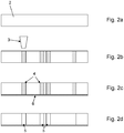
- figure 1 1 shows the individual process steps involved in making a plurality of openings in an interposer 1 with a substrate 2 intended as a contacting element in printed circuit board production.
- laser radiation 3 is directed onto the surface of the substrate 2.
- the substrate 2 has a boro-aluminosilicate as a significant proportion of the material in order to ensure a temperature expansion similar to that of silicon.
- the material thickness d of the substrate 2 is between 50 ⁇ m and 500 ⁇ m.
- the exposure time of the laser radiation 3 is chosen to be extremely short, so that only a modification of the substrate 2 occurs concentrically around a beam axis of the laser beam, without there being any significant continuous destruction or a recess of the substrate material. In particular, the exposure time is limited to a single pulse.
- the laser is operated with a wavelength for which the substrate 2 is transparent.
- a modified area 4 is in Figure 1b shown.
- Figure 1c In the method step shown, due to the action of a caustic liquid or a caustic gas (not shown), anisotropic material removal occurs in those areas 4 of the substrate 2 that have previously been modified by the laser radiation 3 . This creates a recess 5 as an opening in the substrate 2 along the cylindrical zone of action.
- FIG 2 a modification of the same method is described, in which the substrate 2 according to the in Figure 2b modification shown is provided with a flat metal layer 6 by the laser radiation 3, as is shown in Figure 2c can be seen. Due to the anisotropic material removal in the modified areas 4, in the next, in Figure 2d illustrated method step on one side of the metal layer 6 closed recesses 5, which form the basis for a later contact.
- FIG. 3 Another variant of the procedure is in figure 3 shown.
- the substrate 2 is covered on both sides with an in Figure 3b Etch resist 7 shown coated.
- the etching resist 7 is removed in a punctiform zone of action and the underlying area of the substrate 2 is modified, as is shown in Figure 3c can be seen.
- the unmodified areas of the surface of the substrate 2 are thus protected from undesirable effects in the subsequent etching process, through which, as in Figure 3d shown, the anisotropic removal of material is carried out by a liquid etching process and corresponding recesses 5 are formed in the substrate 2.
- a so-called stripping process as in Figure 3e shown, the dispensable etching resist 7 removed after completion of the etching process.
- the intensity-dependent focal point 9a, 9b, 9c thus migrates along the beam axis Z, starting from a distance to a rear side 11 of the substrate 2, in which Figure 4a Position shown in the direction of the laser processing head 10 and thus reaches all positions along the beam axis Z between the back 11 and a front side 12 facing the laser processing head 10 in a continuous movement, so that it leads to the desired modification in the area of the entire main extent of the recesses to be introduced later.
- an additional laser processing head 13 is only shown in outline, through which the laser radiation 3 of a pulsed laser, in addition to a continuously emitting laser source connected to the laser processing head 10, is directed either through the transmissive medium 8 or bypassing it onto the substrate 2.
- the in figure 5 shown intensity I of a single pulse P of the laser radiation 3 amplified accordingly by the intensity of the continuously emitting laser source.
Landscapes
- Engineering & Computer Science (AREA)
- Physics & Mathematics (AREA)
- Optics & Photonics (AREA)
- Plasma & Fusion (AREA)
- Mechanical Engineering (AREA)
- Chemical & Material Sciences (AREA)
- Chemical Kinetics & Catalysis (AREA)
- General Chemical & Material Sciences (AREA)
- Oil, Petroleum & Natural Gas (AREA)
- Laser Beam Processing (AREA)
- Electromagnetism (AREA)
- Surface Treatment Of Glass (AREA)
Description
- Die Erfindung betrifft ein Verfahren gemäß dem Oberbegriff des Anspruchs 1 (siehe zum Beispiel
JP2005288503 - Derartige Substrate werden als sogenannte Interposer zur elektrischen Verbindung der Anschlüsse mehrerer homogener oder heterogener Mikrochips eingesetzt. Der Interposer besteht im Allgemeinen aus Glas oder Silizium und enthält beispielsweise Kontaktflächen, Umverdrahtungen, Durchkontaktierungen sowie aktive und nicht aktive Komponenten.
- Ein Mikrochip als Prozessorkern hat typischerweise auf seiner Unterseite auf relativ kleiner Fläche verteilt mehrere Hundert Kontaktpunkte in engem Abstand zueinander. Wegen dieses engen Abstandes können diese Kontaktpunkte nicht direkt auf eine Schaltungsplatte, das sogenannte Motherboard, aufgebracht werden. Es wird deshalb ein Interposer als Verbindungselement eingesetzt, mit welchem die Kontaktierungsbasis verbreitert werden kann.
- Als Interposer wird in der Praxis beispielsweise eine mit Glasfaser verstärkte Epoxydharzplatte eingesetzt, die mit einer Anzahl von Löchern versehen ist. Auf der Oberfläche der Glasfasermatte laufen Leiterbahnen, die in die jeweiligen Löcher hineinführen, um diese zu verfüllen, und auf der anderen Seite der Glasfasermatte bis zu den Anschlusskontakten des Prozessorkernes führen. Bei Auftreten von Erwärmung kommt es allerdings zu unterschiedlichen Ausdehnungen zwischen dem Kernprozessor und der Glasfasermatte und damit zu mechanischen Spannungen zwischen diesen beiden Komponenten.
- Um die infolge der unterschiedlichen Temperaturausdehnungskoeffizienten auftretenden Spannungen zu reduzieren, werden daher auch Silizium-Interposer eingesetzt. Die Silizium-Interposer können in der in der Halbleiterbranche üblichen Art und Weise verarbeitet werden. Die Herstellung von siliziumbasierten Interposern ist allerdings sehr teuer, sodass es zunehmend Bestrebungen gibt, diese durch kostengünstigeres Glasmaterial zu ersetzen, da Glas hinsichtlich seiner Temperaturausdehnung an Silizium angepasst werden kann.
- Als Herausforderung gestaltet sich hier die Verarbeitung des Glases zu gebrauchsfähigen Interposern. Insbesondere die wirtschaftliche Einbringung der Vielzahl von Durchbrechungen in das Substrat zur Durchkontaktierung ist im Stand der Technik noch nicht gelöst.
- So ist aus der
EP 2 503 859 A1 ein Verfahren bekannt, bei dem ein Substrat mit Durchgangslöchern versehen wird, wobei das Substrat aus einem Isolator wie Glas, beispielsweise Silikatglas, Saphir, Kunststoff oder Keramik und Halbleitern wie Silizium besteht. Das Substrat wird mit einem Laser, beispielsweise einem Femtosekundenlaser, bestrahlt, der auf einen Fokuspunkt an einer gewünschten Position innerhalb des Substrates fokussiert wird. Die Durchgangslöcher werden mit einem Verfahren erzeugt, bei dem das Substrat mit den durch den Laser modifizierten Bereichen in eine Ätzlösung getaucht wird und so die modifizierten Bereiche aus dem Substrat entfernt werden. Dieses Ätzen nutzt den Effekt, dass im Vergleich zu Bereichen des Substrates, die nicht modifiziert wurden, der modifizierte Bereich extrem schnell geätzt wird. Auf diese Weise können Sackbohrungen oder Durchgangsöffnungen erzeugt werden. Für das Füllen der Durchgangsöffnung eignet sich eine Kupferlösung. Um eine gewünschte "Tiefenwirkung", also ein Durchgangsloch zwischen den Substrataußenseiten zu erreichen, muss der Fokuspunkt bei fortgesetzter Bestrahlung entsprechend verlagert, also in Richtung der Z-Achse nachgeführt werden. - Ganz allgemein ist die Kombination einer selektiven Laserbehandlung mit einem nachfolgenden Ätzprozess als selektives laserinduziertes Ätzen auch unter der Bezeichnung ISLE bekannt (In-volume selective laser-induced etching). Dieses Verfahren dient der Herstellung von Mikrobauteilen, Kanälen und geformten Ausschnitten in transparenten Materialien wie Gläsern oder Saphir. Die Miniaturisierung von Produkten für die Mikrooptik, Medizintechnik und Mikrosystemtechnik erfordert die Herstellung von Komponenten mit Abmessungen im Bereich von Mikrometern und mit Strukturgenauigkeiten von bis zu 100 nm. Das ISLE-Verfahren ist ein geeignetes Fertigungsverfahren für Strukturen aus und in transparenten Materialien. Durch die Fokussierung der Laserstrahlung im Inneren des Werkstückes wird das Material in einem kleinen Volumen (einige Kubikmikrometer) strukturell verändert. Beispielsweise wird die Kristallstruktur von Saphir in eine amorphe glasartige Struktur umgewandelt, welche 10.000-fach schneller geätzt wird als das Ausgangsmaterial. Durch Bewegen des Laserfokus durch das Werkstück werden zusammenhängende modifizierte Gebiete erzeugt, welche nachfolgend mittels Kaliumhydroxid oder Flusssäure in wässriger Lösung chemisch geätzt und entfernt werden. Aus der
DE 10 2010 025 966 B4 ist ein Verfahren bekannt, bei dem in einem ersten Schritt auf das Substrat fokussierte Laserimpulse gerichtet werden, deren Strahlungsintensität so stark ist, dass es zu lokaler, athermischer Zerstörung entlang eines filamentartigen Kanales im Glas kommt. In einem zweiten Verfahrensschritt werden die filamentartigen Kanäle zu Löchern aufgeweitet, indem gegenüberstehenden Elektroden Hochspannungsenergie zugeführt wird, was zu dielektrischen Durchbrüchen durch das Substrat entlang der filamentartigen Kanäle führt. Diese Durchbrüche erweitern sich durch elektrothermische Aufheizung und Verdampfung von Lochmaterial, bis der Vorgang bei Erreichen des gewünschten Lochdurchmessers durch Abschalten der Energiezufuhr gestoppt wird. Alternativ oder zusätzlich können die Kanäle auch durch reaktive Gase aufgeweitet werden, die mittels Düsen auf die Lochungsstellen gerichtet werden. Die Durchbruchsstellen können auch durch zugeführtes Ätzgas aufgeweitet werden. Als nachteilig erweist sich der vergleichsweise aufwendige Vorgang, der dadurch entsteht, dass zuerst durch die athermische Zerstörung das Substrat durchbrochen und im nächsten Schritt der Durchmesser der filamentartigen Kanäle zu Löchern aufgeweitet werden muss. - Ferner ist aus der
US 6,400,172 B1 das Einbringen von Durchbrechungen in Halbleitermaterialien mittels Laser bekannt. - Der Erfindung liegt die Aufgabe zugrunde, eine Möglichkeit zu schaffen, ein Verfahren zum Einbringen von Durchbrechungen wesentlich zu vereinfachen und insbesondere den Zeitaufwand für die Durchführung zu vermindern.
- Die Aufgabe wird erfindungsgemäß mit einem Verfahren gemäß den Merkmalen des Anspruches 1 gelöst. Die weitere Ausgestaltung der Erfindung ist den Unteransprüchen zu entnehmen.
- Erfindungsgemäß ist also ein Verfahren vorgesehen, bei dem die Laserstrahlung zunächst durch ein transmissives Medium, insbesondere ein Glas, hindurch gelenkt wird, wobei das Medium einen größeren intensitätsabhängigen Brechungsindex als Luft aufweist, und anschließend auf das Substrat trifft und die Laserstrahlung durch nichtlineare Selbstfokussierung innerhalb der Pulsdauer eines Einzelpulses durch das unveränderte, optische System mit einer von der ursprünglichen Brennweite abweichenden Brennweite fokussiert wird. Die Erfindung macht sich dabei zunutze, dass die Intensität eines gepulsten Lasers bezogen auf einen Einzelpuls nicht konstant ist, sondern über den zeitlichen Verlauf des Einzelpulses eine bis zu einem Maximum ansteigende und danach abfallende Intensität aufweist. Indem aufgrund der zunehmenden Intensität auch der Brechungsindex, bezogen auf einen Einzelpuls über den zeitlichen Verlauf entsprechend einer Normalverteilung, bis zu einem Maximum zunimmt, verändert sich die Brennweite des optischen Systems, also der Abstand von einem Laserbearbeitungskopf bzw. der Linse, und zwar unabhängig von der durch die Fokussieroptik bestimmten geometrischen Fokuslage. Dieser Effekt wird durch das transmissive Medium quasi derart verstärkt, dass der Abstand der Fokuslagen zwischen einer maximalen und einer minimalen Intensität zumindest der gewünschten Längserstreckung, also der Tiefe der einzubringenden Ausnehmung entspricht. Daraus ergibt sich in verblüffend einfacher Weise eine örtliche Verlagerung in Richtung der Strahlachse während der Dauer eines Einzelpulses, die zu der gewünschten Modifikation im Bereich der gesamten Haupterstreckung in Richtung der Strahlachse der später einzubringenden Ausnehmungen führt. Dabei kann auf eine Nachführung der Fokuslage, wie dies beim Stand der Technik unvermeidlich ist, verzichtet werden. Insbesondere ist also keine Steuerung für die Bewegung des Laserfokus durch das Substrat erforderlich. Damit entfällt erfindungsgemäß nicht nur der hierzu erforderliche Steuerungsaufwand, sondern auch die Bearbeitungsdauer wird erheblich, beispielsweise auf die Dauer eines Einzelpulses reduziert. Der nichtlineare Brechungsindex des transmissiven Mediums hängt dabei linear von der Intensität ab, sodass die Auswahl hinsichtlich eines geeigneten Materials sowie der geeigneten Abmessungen von der Intensität der eingesetzten Laserstrahlung abhängt.
- Dabei wird der Laserstrahl derart kurzzeitig auf das Substrat gerichtet, dass lediglich eine Modifikation des Substrates entlang einer Strahlachse des Laserstrahles erfolgt, ohne dass es zu einer das Substrat durchdringenden Ausnehmung des Substrates kommt, wobei im nächsten Schritt ein anisotroper Materialabtrag nur in denjenigen Bereichen des Substrates durchgeführt wird, die zuvor eine Modifikation mittels des Laserstrahles erfahren haben, und so eine Ausnehmung oder Durchbrechung in das Substrat eingebracht wird. Obwohl der erfindungsgemäße Prozess noch nicht abschließend verstanden worden ist, wird derzeit davon ausgegangen, dass es aufgrund der Lasereinwirkung bei der Modifikation zu einer chemischen Umwandlung des Substratmaterials kommt, welche nur geringe Auswirkungen auf die physikalischen Eigenschaften bzw. die äußerliche Beschaffenheit des Substrates hat. Der Laserenergieeintrag dient dabei zur Anregung bzw. Auslösung einer Reaktion und einer Modifikation durch Umwandlung, deren Wirkung erst im nachfolgenden Verfahrensschritt zu dem gewünschten Materialabtrag genutzt wird.
- Indem der anisotrope Materialabtrag durch ein Ätzverfahren, insbesondere durch Flüssigätzen, Trockenätzen oder Dampfphasenätzen, oder durch Verdampfen mittels Hochspannung oder Hochfrequenz erfolgt, ist für den eigentlichen Materialabtrag kein sequentielles, sondern ein flächig einwirkendes Abtragsverfahren nutzbar, welches lediglich sehr geringe Anforderungen an den Prozess stellt. Vielmehr lässt sich über die Einwirkungsdauer der Materialabtrag quantitativ und qualitativ für alle in der beschriebenen Weise vorbehandelten und dementsprechend modifizierten Bereiche zugleich durchführen, sodass der Zeitaufwand für die Erzeugung der Vielzahl der Ausnehmungen oder Durchbrechungen in der Summe wesentlich reduziert ist.
- Der Fokuspunkt bei minimaler Intensität könnte auf eine äußere Oberfläche des Substrates gerichtet werden. Als besonders Erfolg versprechend hat es sich hingegen bereits erwiesen, wenn die Laserstrahlung auf eine abgewandte Seite des Substrates beabstandet zu diesem fokussiert wird, sodass der Fokuspunkt der Laserstrahlung so eingestellt wird, dass dieser auf einer der Laserstrahlung abgewandten Rückseite mit Abstand zu der Oberfläche des Substrates liegt. Hierdurch wird also zunächst der Laserstrahl auf einen außerhalb des Substrates liegenden Fokuspunkt gerichtet. Der aufgrund der zunehmenden Intensität veränderte Brechungsindex führt dann zu einer örtlichen Verlagerung des Fokuspunktes entlang der Strahlachse durch das Substrat hindurch. Dadurch wird sichergestellt, dass jeder Fokuspunkt innerhalb des Substrates mit einer zur Erzeugung der Modifikation ausreichend hohen Intensität beaufschlagt ist.
- Selbstverständlich kann die Dauer der Strahleinwirkung bei unveränderter relativer Position des Laserbearbeitungskopfes gegenüber dem Substrat mehrere Pulslängen umfassen, um so beispielsweise die Modifikation des Substratmaterials weiter zu optimieren. Besonders vorteilhaft ist es hingegen, wenn die Laserstrahlung für die Dauer eines Einzelpulses auf einem jeweiligen Fokuspunkt gelenkt wird. Somit sind also vorhergehende ebenso wie nachfolgende Pulse des Laserstrahles auf in der Ebene des Substrates beabstandete Positionen gerichtet, sodass benachbarte Fokuspunkte einen Abstand in der Ebene des Substrates aufweisen.
- Die Modifikationen könnten durch eine Laserbearbeitung eingebracht werden, bei der eine Positionierung des Laserbearbeitungskopfes und die Laserbearbeitung abwechselnd durchgeführt werden. Vorzugsweise wird hingegen, während die Laserstrahlung auf das Substrat gelenkt wird, eine stetige Relativbewegung zwischen dem Laserstrahl bzw. dem Laserbearbeitungskopf und dem Substrat durchgeführt, sodass also der Laserstrahl kontinuierlich in einer "fliegenden" Bewegung über das Substrat geführt wird, sodass also eine ununterbrochene Änderung der Relativposition eine extrem schnelle Bearbeitungsdauer des Substrates ergibt. Insbesondere kann die relative Position des Substrates in Bezug auf den Laserstrahl mit konstanter Geschwindigkeit verändert werden, sodass bei einer konstanten Pulsfrequenz der Abstand der zu erzeugenden Modifikationen einem vorbestimmten Rastermaß folgt.
- Besonders bevorzugt wird der Laser mit einer Wellenlänge betrieben, für die das Substrat transparent ist, sodass eine Durchdringung des Substrates sichergestellt ist. Insbesondere wird dadurch eine im Wesentlichen zylindrische Modifikationszone koaxial zu der Laserstrahlachse herum sichergestellt, die zu einem konstanten Durchmesser der Durchbrechung oder der Ausnehmung führt.
- Darüber hinaus kann es auch von Vorteil sein, wenn durch den Laser zusätzlich auch ein Oberflächenbereich abgetragen wird, um die Einwirkungszone des anisotropen Abtrages derart auszugestalten, dass ein kegelförmiger Einlassbereich der Durchbrechung entsteht. Auf diese Weise kann die spätere Durchkontaktierung vereinfacht werden. Zudem wird in diesem Bereich beispielsweise die Einwirkung eines Ätzmittels konzentriert.
- Die Pulsdauer kann gegenüber den aus dem Stand der Technik bekannten Verfahren wesentlich reduziert werden. Bei einer besonders vorteilhaften Ausgestaltung des erfindungsgemäßen Verfahrens kann der Laser mit einer Pulsdauer von weniger als 50 ps, vorzugsweise weniger als 20 ps betrieben werden.
- Bei einer anderen, ebenfalls besonders Erfolg versprechenden Ausgestaltung der Erfindung wird das Substrat insbesondere nach der Modifikation mit einer flächigen, zumindest einzelnen, insbesondere eine Vielzahl von nachfolgend einzubringenden Durchbrechungen abdeckenden Metallschicht versehen. In einem folgenden Schritt werden die modifizierten Bereiche so abgetragen, dass eine von der Metallschicht einseitig verschlossene Ausnehmung erzeugt wird. Dabei wird die Metallschicht vorzugsweise nach der Modifikation, jedoch vor dem Materialabtrag aufgebracht, sodass nach dem Materialabtrag die beispielsweise als Leiterbahn aufgebrachte Metallschicht die Ausnehmung verschließt und dadurch zugleich eine optimale Basis für eine daran anzubringende Kontaktierung bildet. Die Durchkontaktierung erfolgt dabei im Bereich der Ausnehmung mit an sich bekannten Verfahren. Indem die Metallschicht als Leiterbahn aufgebracht wird, kann zudem in einfacher Weise ein gewünschtes Schaltbild erzeugt werden.
- Bei einer anderen, ebenfalls besonders Erfolg versprechenden Ausgestaltung des Verfahrens wird das Substrat vor der Laserbehandlung mit einem Ätzresist auf zumindest einer Oberfläche flächig beschichtet. Durch Einwirkung eines Laserstrahles wird zugleich in einer punktförmigen Einwirkungszone das Ätzresist auf zumindest einer Oberfläche abgetragen und die Modifikation in dem Substrat erzeugt. Auf diese Weise werden die nicht modifizierten Bereiche vor einer unerwünschten Einwirkung im nachfolgenden Ätzprozess geschützt und die Oberfläche daher nicht beeinträchtigt. Dabei behindert das Ätzresist nicht die Modifikation des darunter liegenden Substrates. Vielmehr ist das Ätzresist für die Laserstrahlung entweder durchlässig oder wird nahezu punktförmig durch die Laserstrahlung abgetragen, beispielsweise also verdampft. Weiterhin ist nicht ausgeschlossen, dass das Ätzresist solche Substanzen enthält, die für die Modifikation unterstützend wirken, beispielsweise also den Modifikationsvorgang beschleunigen.
- Selbstverständlich kann vor dem Auftrag des Ätzresists auf eine der Außenflächen des Substrates die vorstehend beschriebene Metallschicht aufgebracht werden, um diese nach dem Entfernen des Ätzresists als Basis für die gewünschte Durchkontaktierung zu verwenden.
- Das Ätzresist könnte nach dem Abschluss der Behandlung auf der Oberfläche des Substrates verbleiben. Vorzugsweise wird jedoch das Ätzresist in an sich bekannter Weise nach dem anisotropen Materialabtrag von der Oberfläche des Substrates entfernt. Grundsätzlich ist das Verfahren nicht auf bestimmte Materialzusammensetzungen des Substrates beschränkt. Besonders Erfolg versprechend ist es allerdings, wenn das Substrat als einen wesentlichen Materialanteil ein Aluminosilikat, insbesondere ein Boro-Aluminosilikat aufweist.
- Die zweitgenannte Aufgabe wird mit einer Vorrichtung mit einem Laserbearbeitungskopf zur Ablenkung einer Laserstrahlung auf ein Substrat dadurch gelöst, dass die Vorrichtung mit einem insbesondere mit zumindest einer ebenen Fläche ausgestatteten oder beispielsweise als eine Planplatte ausgeführten transmissiven Medium mit einem größeren intensitätsabhängigen Brechungsindex bzw. mit einer größeren intensitätsabhängigen Brechzahl als Luft ausgestattet ist, welches zwischen dem Laserbearbeitungskopf und dem Substrat angeordnet ist, derart, dass die Laserstrahlung durch das transmissive Medium hindurch auf das Substrat ablenkbar ist. Hierdurch wird erfindungsgemäß der intensitätsabhängige Brechungsindex bzw. die intensitätsabhängige Brechzahl des transmissiven Mediums genutzt, um in Verbindung mit einem gepulsten Laser während der Dauer jedes Einzelpulses und der damit einhergehenden Schwankung der Intensität während des Einzelpulses eine axiale Veränderung der Fokuslage zu erzeugen. Somit ist also anders als beim Stand der Technik die Fokuslage zumindest während der Dauer eines Einzelpulses nicht unverändert, sondern die Fokuslage verlagert sich bezogen auf die Gesamtdauer des Einzelpulses entlang einer Linie auf der Strahlachse. Es ist leicht verständlich, welche wesentlichen Vorteile sich bei der vorliegenden Erfindung dadurch ergeben, dass sich die Fokuslage ohne eine Nachführung der Fokussieroptik des Laserbearbeitungskopfes verlagert. Insbesondere wird dadurch die Bearbeitungsdauer wesentlich verkürzt und auch der Steuerungsaufwand vermindert. Beispielsweise kann bei einem ebenen Substrat auf die Nachführung der Z-Achse verzichtet werden.
- Dabei ist grundsätzlich auch eine Variante denkbar, bei der das transmissive Medium in Richtung des Strahlenganges vor einer Fokussieroptik des Laserbearbeitungskopfes an diesem angeordnet ist, sodass die Laserstrahlung zunächst durch das transmissive Medium und anschließend durch die Fokussieroptik hindurch auf das Substrat gerichtet wird.
- Der Effekt der intensitätsabhängigen Lichtbrechung kann selbstverständlich an den jeweiligen Verwendungszweck beispielsweise dadurch angepasst werden, dass das transmissive Medium entsprechend angepasst oder ausgetauscht wird oder dass der Laserstrahl mehrere transmissive Medien oder dasselbe Medium mehrfach durchläuft.
- Der Fokuspunkt könnte auf eine dem Laserbearbeitungskopf abgewandte Rückseite des Substrates gerichtet werden und das transmissive Medium so beschaffen sein, dass der intensitätsabhängige Fokuspunkt bei dem Intensitätsmaximum eine dem Laserbearbeitungskopf zugewandte Vorderseite erreicht. Besonders praxisgerecht ist es hingegen, wenn die Laserstrahlung auf einen Fokuspunkt beabstandet zu einer dem Laserbearbeitungskopf abgewandten Rückseite des Substrates ablenkbar ist, sodass die Rückseite des Substrates nicht bei einem Intensitätsminimum, sondern erst im Verlauf zunehmender Intensität erreicht wird. Somit wird eine für die zu erzielende Modifikation stets ausreichende Intensität der Laserstrahlung innerhalb des Substrates sichergestellt.
- Zur Bearbeitung ist grundsätzlich jeder gepulste Laser geeignet, wobei sich bereits ein Laser mit einer Pulsdauer von weniger als 50 ps, vorzugsweise weniger als 20 ps als besonders zweckmäßig erwiesen hat.
- Zudem ist es besonders sinnvoll, wenn der Laserbearbeitungskopf zur Fokussierung eine Fokussieroptik mit einer numerischen Apertur (NA) größer als 0,3, insbesondere größer als 0,4 aufweist.
- Eine besonders vielversprechende Gestaltung der erfindungsgemäßen Vorrichtung wird auch dadurch erreicht, dass die Fokussieroptik eine Gradienten-Index-Linse aufweist. Durch den Einsatz einer solchen, auch als GRIN-Linse bekannten Linse führt der in radialer Richtung abnehmende Brechungsindex dazu, dass die anderenfalls vorhandene Abschwächung der Intensität im Randbereich der Linse weitgehend ausgeglichen wird.
- Weiterhin erweist es sich als vorteilhaft, wenn das transmissive Medium aus Glas, insbesondere aus Quarzglas besteht, um so einen ausgeprägten intensitätsabhängigen Brechungsindex zu realisieren.
- Dabei ist das transmissive Medium vorzugsweise mit dem Laserbearbeitungskopf verbunden und mit diesem gemeinsam beweglich angeordnet sowie an dem Laserbearbeitungskopf insbesondere austauschbar angeordnet. Hierzu eignet sich beispielsweise eine Schnellfixierung.
- Vorzugsweise ist die Vorrichtung zusätzlich zu einem Pulslaser mit einem kontinuierlich emittierenden Laser ausgestattet, wobei das transmissive Medium transparent für die Wellenlänge des kontinuierlich emittierenden Lasers ist und der kontinuierlich emittierende Laser durch das Medium hindurch auf das Substrat bzw. unter Umgehung des transmissiven Mediums auf das Substrat gerichtet wird. Die Wellenlänge des Pulslasers und des kontinuierlich emittierenden Lasers können dabei unterschiedlich sein. Weiterhin können die Laserstrahlungen der verschiedenen Laserquellen von unterschiedlichen Seiten auf das Substrat gerichtet werden.
- Die Erfindung lässt verschiedene Ausführungsformen zu. Zur weiteren Verdeutlichung ihres Grundprinzips ist eine davon in der Zeichnung dargestellt und wird nachfolgend beschrieben. Diese zeigt in
- Fig. 1
- ein Ablaufdiagramm mit mehreren Verfahrensschritten zum Einbringen einer Mehrzahl von Durchbrechungen in ein Substrat durch anisotropen Materialabtrag;
- Fig. 2
- eine Verfahrensvariante, bei der vor dem anisotropen Materialabtrag eine Metallschicht aufgebracht wird;
- Fig. 3
- eine weitere Verfahrensvariante, bei der in einem ersten Verfahrensschritt ein Ätzresist auf das Substrat aufgebracht wird;
- Fig. 4
- die intensitätsabhängige Fokuslage während eines Einzelpulses;
- Fig. 5
- eine Diagrammdarstellung der Intensitätsverteilung über die Zeit während der Dauer eines Einzelpulses.
-
Figur 1 zeigt die einzelnen Verfahrensschritte beim Einbringen einer Mehrzahl von Durchbrechungen in einen als Kontaktierungselement in der Leiterplattenfertigung bestimmten Interposer 1 mit einem Substrat 2. Hierzu wird eine Laserstrahlung 3 auf die Oberfläche des Substrates 2 gerichtet. Das Substrat 2 weist als einen wesentlichen Materialanteil ein Boro-Aluminosilikat auf, um so eine Temperaturausdehnung ähnlich der von Silizium sicherzustellen. Die Materialstärke d des Substrates 2 beträgt dabei zwischen 50 µm und 500 µm. Die Einwirkungsdauer der Laserstrahlung 3 wird dabei äußerst kurz gewählt, sodass lediglich eine Modifikation des Substrates 2 konzentrisch um eine Strahlachse des Laserstrahles eintritt, ohne dass es zu einer wesentlichen durchgehenden Zerstörung bzw. einer Ausnehmung des Substratmaterials kommt. Insbesondere wird die Einwirkungsdauer auf einen Einzelpuls beschränkt. Hierzu wird der Laser mit einer Wellenlänge betrieben, für die das Substrat 2 transparent ist. Ein derart modifizierter Bereich 4 ist inFigur 1b dargestellt. In einem nachfolgenden, inFigur 1c dargestellten Verfahrensschritt kommt es aufgrund der Einwirkung einer nicht dargestellten ätzenden Flüssigkeit oder eines ätzendes Gases zu einem anisotropen Materialabtrag in denjenigen Bereichen 4 des Substrates 2, die zuvor eine Modifikation durch die Laserstrahlung 3 erfahren haben. Entlang der zylindrischen Einwirkungszone entsteht dadurch eine Ausnehmung 5 als Durchbrechung in dem Substrat 2. - In
Figur 2 wird eine Abwandlung desselben Verfahrens beschrieben, bei der das Substrat 2 nach der inFigur 2b gezeigten Modifikation durch die Laserstrahlung 3 mit einer flächigen Metallschicht 6 versehen wird, wie dies inFigur 2c zu erkennen ist. Durch den anisotropen Materialabtrag in den modifizierten Bereichen 4 entstehen im nächsten, inFigur 2d dargestellten Verfahrensschritt einseitig von der Metallschicht 6 verschlossene Ausnehmungen 5, welche die Basis für eine spätere Kontaktierung bilden. - Eine weitere Variante des Verfahrens ist in
Figur 3 dargestellt. Dabei wird das Substrat 2 vor der Laserbehandlung mittels der Laserstrahlung 3 beidseitig mit einem inFigur 3b dargestellten Ätzresist 7 beschichtet. Aufgrund der Einwirkung der Laserstrahlung 3 kommt es in einer punktförmigen Einwirkungszone zugleich zu einem Abtrag des Ätzresists 7 und zu einer Modifikation des darunter liegenden Bereiches des Substrates 2, wie dies inFigur 3c zu erkennen ist. Die nicht modifizierten Bereiche der Oberfläche des Substrates 2 sind so vor einer unerwünschten Einwirkung im nachfolgenden Ätzprozess geschützt, durch den, wie inFigur 3d dargestellt, der anisotrope Materialabtrag durch ein Flüssigätzverfahren erfolgt und entsprechende Ausnehmungen 5 in dem Substrat 2 entstehen. Durch ein sogenanntes Stripping-Verfahren wird, wie inFigur 3e gezeigt, das nach Abschluss des Ätzverfahrens entbehrliche Ätzresist 7 abgetragen. - Anhand der
Figuren 4 und5 wird nachstehend ein wesentlicher Effekt während der Laserbearbeitung des Substrates 2 näher dargestellt. Dabei handelt es sich um die die intensitätsabhängige Fokuslage während eines Einzelpulses P. Die Erfindung geht dabei von der Erkenntnis aus, dass die Intensität I eines Einzelpulses P der Laserstrahlung 3 nicht konstant ist, sondern wie inFigur 5 dargestellt über den zeitlichen Verlauf des Einzelpulses eine von einem Minimum Ia über einen Mittelwert Ib bis zu einem Maximum Ic ansteigende und danach abfallende Intensität beispielsweise entsprechend einer Normalverteilung aufweist. Zugleich ändert sich aufgrund der veränderlichen Intensität I der Brechungsindex, insbesondere auch eines transmissiven Mediums 8, bezogen auf einen Einzelpuls P über den zeitlichen Verlauf t. Dadurch verändern sich auch die in denFiguren 4a bis 4c dargestellten intensitätsabhängigen Fokuslagen 9a, 9b, 9c der Laserstrahlung 3 unabhängig von der durch eine Fokussieroptik eines Laserbearbeitungskopfes 10 bestimmten geometrischen Fokuslage. Dieser Effekt wird durch das zwischen dem Laserbearbeitungskopf 10 und dem Substrat 2 angeordnete transmissive Medium 8 beispielsweise aus Glas, das einen größeren intensitätsabhängigen Brechungsindex als Luft aufweist, so verstärkt, dass der Abstand der Fokuslagen 9a, 9c zwischen einer maximalen Intensität Ic und einer minimalen Intensität Ia zumindest der gewünschten Längserstreckung, also der Tiefe der einzubringenden Ausnehmung bzw. wie dargestellt im Falle eines einzubringenden Durchgangsloches der Materialstärke d des Substrates 2 entspricht. Der intensitätsabhängige Fokuspunkt 9a, 9b, 9c wandert also entlang der Strahlachse Z ausgehend von einem zu einer Rückseite 11 des Substrates 2 beabstandeten, in derFigur 4a gezeigten Position in Richtung des Laserbearbeitungskopfes 10 und erreicht so in einer stetigen Bewegung alle Positionen entlang der Strahlachse Z zwischen der Rückseite 11 und einer dem Laserbearbeitungskopf 10 zugewandten Vorderseite 12, sodass es zu der gewünschten Modifikation im Bereich der gesamten Haupterstreckung der später einzubringenden Ausnehmungen kommt. - Ergänzend ist in
Figur 4a lediglich andeutungsweise ein zusätzlicher Laserbearbeitungskopf 13 dargestellt, durch den die Laserstrahlung 3 eines gepulsten Lasers ergänzend zu einer mit dem Laserbearbeitungskopf 10 verbundenen kontinuierlich emittierenden Laserquelle wahlweise durch das transmissive Medium 8 hindurch oder unter Umgehung desselben auf das Substrat 2 gerichtet wird. Hierdurch wird die inFigur 5 dargestellte Intensität I eines Einzelpulses P der Laserstrahlung 3 entsprechend durch die Intensität der kontinuierlich emittierenden Laserquelle verstärkt.
Claims (14)
- Verfahren zum Einbringen einer Mehrzahl von Ausnehmungen (5) in ein insbesondere ebenes Substrat (2) mittels eines optischen Systems, wobei die Dicke des Substrates (2) im Bereich der einzubringenden Ausnehmungen (5) 2 mm nicht übersteigt, mittels gepulster Laserstrahlung (3) mit einer Pulsdauer (t), wobei das Substratmaterial des Substrates (2) für die Laserwellenlänge zumindest teilweise transparent ist und die Laserstrahlung (3) mit Hilfe des optischen Systems der Brennweite (f1) fokussiert wird und die Intensität der Laserstrahlung (3) zu einer Modifikation des Substrates (2) entlang einer Strahlachse (Z) der Laserstrahlung (3), jedoch nicht zu einem durchgehenden Materialabtrag führt, wobei die Laserstrahlung (3) durch nichtlineare Selbstfokussierung innerhalb der Pulsdauer (t) eines Einzelpulses (P) durch dasselbe, an sich unveränderte, optische System mit einer von der ursprünglichen Brennweite (f1) verschiedenen Brennweite (f2) fokussiert wird, dadurch gekennzeichnet, dass die Laserstrahlung (3) zunächst durch ein transmissives Medium (8) hindurch gelenkt wird, wobei das transmissive Medium (8) einen größeren intensitätsabhängigen Brechungsindex als Luft aufweist und1. die Intensität (I) eines Einzelpulses (P) der Laserstrahlung (3) über den zeitlichen Verlauf des Einzelpulses eine von einem Minimum (Ia) über einen Mittelwert bis zu einem Maximum (Ic) ansteigende und danach abfallende Intensität aufweist,2. und sich dadurch die Brennweite des optischen Systems unabhängig von der durch die Fokussieroptik bestimmten geometrischen Fokuslage verändert, und dieser Effekt durch das transmissive Medium (8) derart verstärkt wird, dass der Abstand der Fokuslagen zwischen einer maximalen und einer minimalen Intensität (I) zumindest der gewünschten Längserstreckung der einzubringenden Ausnehmung (5) entspricht,3. wodurch sich unabhängig von der durch die Fokussieroptik des Laserbearbeitungskopfes (10) bestimmten geometrischen Fokuslage die intensitätsabhängigen Fokuslagen der Laserstrahlung (3) verändern, sodass im nächsten Schritt ein anisotroper Materialabtrag hauptsächlich in denjenigen Bereichen erfolgt, die zuvor eine Modifikation mittels der Laserstrahlung (3) erfahren haben, und so eine Ausnehmung (5) in das Substrat (2) eingebracht wird.
- Verfahren nach Anspruch 1, dadurch gekennzeichnet, dass der Abstand der Fokuslage zwischen einer maximalen und einer minimalen Intensität (I) größer ist als die Dicke des Substrates (2) im Bereich der einzubringenden Ausnehmung (5).
- Verfahren nach zumindest einem der vorhergehenden Ansprüche, dadurch gekennzeichnet, dass das Substrat (2) als einen wesentlichen Materialanteil Glas, Saphir und/oder Silizium aufweist.
- Verfahren nach zumindest einem der vorhergehenden Ansprüche, dadurch gekennzeichnet, dass der anisotrope Materialabtrag durch Ätzung in Fluorwasserstoffsäure durchgeführt wird.
- Verfahren nach zumindest einem der vorhergehenden Ansprüche, dadurch gekennzeichnet, dass das Substrat (2) vor der Laserbestrahlung zumindest einseitig mit einem Ätzresist (7) beschichtet wird.
- Verfahren nach Anspruch 5, dadurch gekennzeichnet, dass das Substrat (2) vor der Laserbehandlung mit einem Ätzresist (7) auf zumindest einer Oberfläche flächig beschichtet wird und dass durch Einwirkung der Laserstrahlung (3) zugleich in einer punktförmigen Einwirkungszone das Ätzresist (7) abgetragen und auf zumindest einer Oberfläche die Modifikation in dem Substrat (2) erzeugt wird.
- Verfahren nach Anspruch 5 oder 6, dadurch gekennzeichnet, dass das Ätzresist (7) nach dem anisotropen Materialabtrag von der Oberfläche des Substrates (2) entfernt wird.
- Verfahren nach zumindest einem der vorhergehenden Ansprüche, dadurch gekennzeichnet, dass das Substrat (2) zumindest einseitig mit einem Metall beschichtet wird.
- Verfahren nach Anspruch 8, dadurch gekennzeichnet, dass das Substrat (2) insbesondere nach der Modifikation mit einer flächigen, zumindest einzelne, insbesondere eine Vielzahl von nachfolgend einzubringenden Ausnehmungen (5) und/oder Durchbrechungen abdeckenden Metallschicht (6) versehen wird und dass in einem folgenden Schritt die modifizierten Bereiche (4) abgetragen werden, sodass von der Metallschicht (6) einseitig verschlossene Ausnehmungen (5) erzeugt werden.
- Verfahren nach zumindest einem der vorhergehenden Ansprüche, dadurch gekennzeichnet, dass die numerische Apertur (NA) des optischen Systems größer ist als 0,3, insbesondere größer als 0,4.
- Verfahren nach zumindest einem der vorhergehenden Ansprüche, dadurch gekennzeichnet, dass die Laserstrahlung (3) für die Pulsdauer (t) eines Einzelpulses (P) auf einen jeweiligen Fokuspunkt (9a, 9b, 9c) gelenkt wird und der jeweilige Fokuspunkt (9a, 9b, 9c) während der Pulsdauer (t) eines Einzelpulses um zumindest 30 µm, insbesondere zumindest 50 µm in Richtung der Strahlachse (Z) der Laserstrahlung (3) verlagert wird.
- Verfahren nach zumindest einem der vorhergehenden Ansprüche, dadurch gekennzeichnet, dass während die Laserstrahlung (3) auf das Substrat (2) einwirkt, das Substrat (2) relativ zu der Laserstrahlung (3) und/oder dem Laserbearbeitungskopf (10) insbesondere unterbrechungsfrei bewegt wird.
- Verfahren nach zumindest einem der vorhergehenden Ansprüche, dadurch gekennzeichnet, dass durch die Laserstrahlung (3) zusätzlich auch ein Oberflächenbereich abgetragen wird.
- Verfahren nach zumindest einem der vorhergehenden Ansprüche, dadurch gekennzeichnet, dass die Laserstrahlung (3) eines gepulsten Lasers durch das transmissive Medium (8) und die Laserstrahlung eines insbesondere kontinuierlich emittierenden Lasers durch das transmissive Medium (8) oder unter Umgehung des transmissiven Mediums (8) auf das Substrat (2) gerichtet wird.
Applications Claiming Priority (3)
| Application Number | Priority Date | Filing Date | Title |
|---|---|---|---|
| DE201310103370 DE102013103370A1 (de) | 2013-04-04 | 2013-04-04 | Verfahren zum Einbringen von Durchbrechungen in ein Glassubstrat sowie ein derart hergestelltes Glassubstrat |
| DE102013112033 | 2013-10-31 | ||
| PCT/DE2014/100118 WO2014161534A2 (de) | 2013-04-04 | 2014-04-03 | Verfahren und vorrichtung zum einbringen von durchbrechungen in ein substrat sowie ein derart hergestelltes substrat |
Publications (2)
| Publication Number | Publication Date |
|---|---|
| EP2964417A2 EP2964417A2 (de) | 2016-01-13 |
| EP2964417B1 true EP2964417B1 (de) | 2022-01-12 |
Family
ID=50792337
Family Applications (1)
| Application Number | Title | Priority Date | Filing Date |
|---|---|---|---|
| EP14726069.9A Active EP2964417B1 (de) | 2013-04-04 | 2014-04-03 | Verfahren zum einbringen von durchbrechungen in ein substrat |
Country Status (9)
| Country | Link |
|---|---|
| US (3) | US10610971B2 (de) |
| EP (1) | EP2964417B1 (de) |
| JP (1) | JP6186016B2 (de) |
| KR (1) | KR101857335B1 (de) |
| CN (1) | CN105102177B (de) |
| ES (1) | ES2908956T3 (de) |
| LT (1) | LT2964417T (de) |
| MY (1) | MY178429A (de) |
| WO (1) | WO2014161534A2 (de) |
Cited By (3)
| Publication number | Priority date | Publication date | Assignee | Title |
|---|---|---|---|---|
| DE102022116783B3 (de) | 2022-07-05 | 2023-09-14 | Lpkf Laser & Electronics Aktiengesellschaft | Mikrostruktur aus Glas, Mikro-Mechanik und zugehörige Verwendung |
| DE102022130976B3 (de) | 2022-11-23 | 2023-11-30 | Lpkf Laser & Electronics Aktiengesellschaft | Monolithische Membran aus Glas, Doppel-Vertikalmembran-Anordnung, mikromechanische Federstruktur und zugehöriges Herstellungsverfahren |
| WO2024008774A1 (de) | 2022-07-05 | 2024-01-11 | Lpkf Laser & Electronics Se | Mikromechanische kammstruktur aus glas sowie zugehöriges verfahren und verwendung |
Families Citing this family (74)
| Publication number | Priority date | Publication date | Assignee | Title |
|---|---|---|---|---|
| AU2011279374A1 (en) | 2010-07-12 | 2013-02-07 | Filaser Usa Llc | Method of material processing by laser filamentation |
| WO2014079478A1 (en) | 2012-11-20 | 2014-05-30 | Light In Light Srl | High speed laser processing of transparent materials |
| EP2754524B1 (de) | 2013-01-15 | 2015-11-25 | Corning Laser Technologies GmbH | Verfahren und Vorrichtung zum laserbasierten Bearbeiten von flächigen Substraten, d.h. Wafer oder Glaselement, unter Verwendung einer Laserstrahlbrennlinie |
| EP2781296B1 (de) | 2013-03-21 | 2020-10-21 | Corning Laser Technologies GmbH | Vorrichtung und verfahren zum ausschneiden von konturen aus flächigen substraten mittels laser |
| CN105189024B (zh) | 2013-04-04 | 2018-01-30 | Lpkf激光电子股份公司 | 用于分离基板的方法和装置 |
| US9102011B2 (en) | 2013-08-02 | 2015-08-11 | Rofin-Sinar Technologies Inc. | Method and apparatus for non-ablative, photoacoustic compression machining in transparent materials using filamentation by burst ultrafast laser pulses |
| US10017410B2 (en) | 2013-10-25 | 2018-07-10 | Rofin-Sinar Technologies Llc | Method of fabricating a glass magnetic hard drive disk platter using filamentation by burst ultrafast laser pulses |
| US9517929B2 (en) | 2013-11-19 | 2016-12-13 | Rofin-Sinar Technologies Inc. | Method of fabricating electromechanical microchips with a burst ultrafast laser pulses |
| US10252507B2 (en) | 2013-11-19 | 2019-04-09 | Rofin-Sinar Technologies Llc | Method and apparatus for forward deposition of material onto a substrate using burst ultrafast laser pulse energy |
| US10005152B2 (en) | 2013-11-19 | 2018-06-26 | Rofin-Sinar Technologies Llc | Method and apparatus for spiral cutting a glass tube using filamentation by burst ultrafast laser pulses |
| US11053156B2 (en) | 2013-11-19 | 2021-07-06 | Rofin-Sinar Technologies Llc | Method of closed form release for brittle materials using burst ultrafast laser pulses |
| US10144088B2 (en) | 2013-12-03 | 2018-12-04 | Rofin-Sinar Technologies Llc | Method and apparatus for laser processing of silicon by filamentation of burst ultrafast laser pulses |
| US9676167B2 (en) | 2013-12-17 | 2017-06-13 | Corning Incorporated | Laser processing of sapphire substrate and related applications |
| US9701563B2 (en) | 2013-12-17 | 2017-07-11 | Corning Incorporated | Laser cut composite glass article and method of cutting |
| US10442719B2 (en) | 2013-12-17 | 2019-10-15 | Corning Incorporated | Edge chamfering methods |
| US9517963B2 (en) | 2013-12-17 | 2016-12-13 | Corning Incorporated | Method for rapid laser drilling of holes in glass and products made therefrom |
| US9850160B2 (en) | 2013-12-17 | 2017-12-26 | Corning Incorporated | Laser cutting of display glass compositions |
| US11556039B2 (en) | 2013-12-17 | 2023-01-17 | Corning Incorporated | Electrochromic coated glass articles and methods for laser processing the same |
| US20150165560A1 (en) | 2013-12-17 | 2015-06-18 | Corning Incorporated | Laser processing of slots and holes |
| US9815730B2 (en) | 2013-12-17 | 2017-11-14 | Corning Incorporated | Processing 3D shaped transparent brittle substrate |
| US9938187B2 (en) | 2014-02-28 | 2018-04-10 | Rofin-Sinar Technologies Llc | Method and apparatus for material processing using multiple filamentation of burst ultrafast laser pulses |
| EP3166895B1 (de) | 2014-07-08 | 2021-11-24 | Corning Incorporated | Verfahren und vorrichtung zur laserbearbeitung von materialien |
| WO2016010991A1 (en) * | 2014-07-14 | 2016-01-21 | Corning Incorporated | Interface block; system for and method of cutting a substrate being transparent within a range of wavelengths using such interface block |
| CN208586209U (zh) | 2014-07-14 | 2019-03-08 | 康宁股份有限公司 | 一种用于在工件中形成限定轮廓的多个缺陷的系统 |
| JP2017530867A (ja) | 2014-07-14 | 2017-10-19 | コーニング インコーポレイテッド | 長さおよび直径の調節可能なレーザビーム焦線を用いて透明材料を加工するためのシステムおよび方法 |
| EP3169479B1 (de) | 2014-07-14 | 2019-10-02 | Corning Incorporated | Verfahren und system zum stoppen von inzidenter rissausbreitung in einem transparenten material |
| US9757815B2 (en) | 2014-07-21 | 2017-09-12 | Rofin-Sinar Technologies Inc. | Method and apparatus for performing laser curved filamentation within transparent materials |
| US10047001B2 (en) | 2014-12-04 | 2018-08-14 | Corning Incorporated | Glass cutting systems and methods using non-diffracting laser beams |
| JP6104354B2 (ja) * | 2014-12-16 | 2017-03-29 | 旭硝子株式会社 | 貫通孔形成方法、貫通孔形成装置、および貫通孔を有するガラス基板の製造方法 |
| KR20170105562A (ko) | 2015-01-12 | 2017-09-19 | 코닝 인코포레이티드 | 다중 광자 흡수 방법을 사용한 열적 템퍼링된 기판의 레이저 절단 |
| US10391588B2 (en) | 2015-01-13 | 2019-08-27 | Rofin-Sinar Technologies Llc | Method and system for scribing brittle material followed by chemical etching |
| JP7292006B2 (ja) | 2015-03-24 | 2023-06-16 | コーニング インコーポレイテッド | ディスプレイガラス組成物のレーザ切断及び加工 |
| EP3274313A1 (de) | 2015-03-27 | 2018-01-31 | Corning Incorporated | Gasdurchlässiges fenster und verfahren zur herstellung davon |
| TW201704177A (zh) * | 2015-06-10 | 2017-02-01 | 康寧公司 | 蝕刻玻璃基板的方法及玻璃基板 |
| CN107835794A (zh) | 2015-07-10 | 2018-03-23 | 康宁股份有限公司 | 在挠性基材板中连续制造孔的方法和与此相关的产品 |
| WO2017034958A1 (en) * | 2015-08-21 | 2017-03-02 | Corning Incorporated | Glass substrate assemblies having low dielectric properties |
| CN107922259B (zh) | 2015-09-04 | 2021-05-07 | Agc株式会社 | 玻璃板的制造方法、玻璃板、玻璃物品的制造方法、玻璃物品以及玻璃物品的制造装置 |
| US10410883B2 (en) | 2016-06-01 | 2019-09-10 | Corning Incorporated | Articles and methods of forming vias in substrates |
| US10794679B2 (en) | 2016-06-29 | 2020-10-06 | Corning Incorporated | Method and system for measuring geometric parameters of through holes |
| EP3508458B1 (de) | 2016-09-01 | 2022-03-16 | Agc Inc. | Verfahren zur herstellung eines glasprodukts |
| JP6923284B2 (ja) | 2016-09-30 | 2021-08-18 | コーニング インコーポレイテッド | 非軸対称ビームスポットを用いて透明被加工物をレーザ加工するための装置及び方法 |
| LT3529214T (lt) | 2016-10-24 | 2021-02-25 | Corning Incorporated | Substrato apdorojimo stotis lakšto formos stiklo substratų lazeriniam mašininiam apdorojimui |
| TW202529282A (zh) * | 2016-11-18 | 2025-07-16 | 美商山姆科技公司 | 用於填充之無鉛材料及導電組件 |
| WO2018155100A1 (ja) | 2017-02-21 | 2018-08-30 | Agc株式会社 | ガラス板およびガラス板の製造方法 |
| CN110291051B (zh) | 2017-02-21 | 2022-04-29 | Agc株式会社 | 玻璃板以及玻璃板的制造方法 |
| TWI681445B (zh) * | 2017-03-06 | 2020-01-01 | 德商Lpkf雷射暨電子股份公司 | 用於製造技術遮罩之方法以及藉助於可再用遮罩施加及/或移除圖案化材料之方法 |
| KR20190116378A (ko) * | 2017-03-06 | 2019-10-14 | 엘피케이에프 레이저 앤드 일렉트로닉스 악티엔게젤샤프트 | 전자기 방사선과 후속 에칭공정을 이용해 재료 안으로 적어도 하나의 리세스를 도입하기 위한 방법 |
| US11072041B2 (en) | 2017-03-06 | 2021-07-27 | Lpkf Laser & Electronics Ag | Method for producing a technical mask |
| CN110545948B (zh) * | 2017-05-15 | 2022-02-25 | Lpkf激光电子股份公司 | 借助激光诱导的深度蚀刻来加工、尤其分割基板的方法 |
| US10580725B2 (en) | 2017-05-25 | 2020-03-03 | Corning Incorporated | Articles having vias with geometry attributes and methods for fabricating the same |
| US11078112B2 (en) * | 2017-05-25 | 2021-08-03 | Corning Incorporated | Silica-containing substrates with vias having an axially variable sidewall taper and methods for forming the same |
| DE112018004409B4 (de) * | 2017-10-04 | 2022-02-17 | Lpkf Laser & Electronics Ag | Optisches Bauelement und Verfahren zu dessen Herstellung |
| MY197514A (en) * | 2017-11-10 | 2023-06-19 | Lpkf Laser & Electronics Ag | Method and device for the integration of semiconductor wafers |
| US12180108B2 (en) | 2017-12-19 | 2024-12-31 | Corning Incorporated | Methods for etching vias in glass-based articles employing positive charge organic molecules |
| JP7407499B2 (ja) * | 2017-12-26 | 2024-01-04 | 株式会社ディスコ | 凹部又は貫通孔の形成方法、電極の形成方法 |
| US11554984B2 (en) | 2018-02-22 | 2023-01-17 | Corning Incorporated | Alkali-free borosilicate glasses with low post-HF etch roughness |
| WO2019191621A1 (en) | 2018-03-30 | 2019-10-03 | Samtec, Inc. | Electrically conductive vias and methods for producing same |
| DE102020100848B4 (de) | 2019-01-29 | 2023-07-27 | Lpkf Laser & Electronics Aktiengesellschaft | Verfahren zur Mikrostrukturierung eines Glassubstrats mittels Laserstrahlung |
| JP7230650B2 (ja) | 2019-04-05 | 2023-03-01 | Tdk株式会社 | 無機材料基板の加工方法、デバイス、およびデバイスの製造方法 |
| DE102019111634A1 (de) * | 2019-05-06 | 2020-11-12 | Lpkf Laser & Electronics Ag | Verfahren zur Herstellung von Mikrostrukturen in einem Glassubstrat |
| WO2020228893A1 (de) * | 2019-05-13 | 2020-11-19 | Lpkf Laser & Electronics Ag | Verfahren zur herstellung eines ein trägersubstrat aufweisenden displays, ein nach diesem verfahren hergestelltes trägersubstrat sowie ein für ein flexibles display bestimmtes deckglas |
| WO2021008700A1 (en) | 2019-07-17 | 2021-01-21 | Scrona Ag | Inkjet print head with contamination robustness |
| WO2021008699A1 (en) | 2019-07-17 | 2021-01-21 | Scrona Ag | Electrohydrodynamic print head with structured feed layer |
| DE102019121827A1 (de) * | 2019-08-13 | 2021-02-18 | Trumpf Laser- Und Systemtechnik Gmbh | Laserätzen mit variierender Ätzselektivität |
| TW202450042A (zh) | 2019-09-30 | 2024-12-16 | 美商山姆科技公司 | 導電通孔和其製造方法 |
| DE102019217466A1 (de) * | 2019-11-12 | 2021-05-12 | Lpkf Laser & Electronics Ag | Reaktionsgefäße aus Glas, Herstellungsverfahren und Verfahren zur Analyse |
| DE102021100144A1 (de) | 2020-01-09 | 2021-07-15 | Lpkf Laser & Electronics Aktiengesellschaft | Verfahren zur Bearbeitung eines Glases |
| KR102311023B1 (ko) * | 2020-05-26 | 2021-10-08 | 윤창희 | 가공 효율성을 향상시킨 이중소재 이체형 플라즈마 에칭 플레이트 |
| DE102020114195A1 (de) * | 2020-05-27 | 2021-12-02 | Lpkf Laser & Electronics Aktiengesellschaft | Verfahren zum Einbringen einer Ausnehmung in ein Substrat |
| EP4296244A1 (de) | 2022-06-21 | 2023-12-27 | LPKF Laser & Electronics SE | Substratträger aus glas zur bearbeitung eines substrats und ein verfahren zu dessen herstellung |
| DE102022127259B4 (de) | 2022-10-18 | 2026-02-12 | Lpkf Laser & Electronics Aktiengesellschaft | Verfahren sowie Vorrichtung zur Abbildung eines Strahls auf ein Objekt und Verfahren zum Einbringen einer Öffnung in ein Werkstück mittels dieses Verfahrens |
| KR102559949B1 (ko) * | 2022-12-15 | 2023-07-26 | 주식회사 에프엠에스 | 유리 기판을 관통하는 홀의 형성 방법 및 금속 플러그 형성 방법 |
| CN116393847A (zh) * | 2023-04-20 | 2023-07-07 | 江苏大学 | 一种二段式飞秒激光加工气膜孔方法 |
| DE102024105120A1 (de) * | 2024-02-23 | 2025-08-28 | Lpkf Laser & Electronics Se | Verfahren zur Integration und/oder Bearbeitung wenigstens eines Substrats sowie Substratstapel |
Citations (2)
| Publication number | Priority date | Publication date | Assignee | Title |
|---|---|---|---|---|
| JPS59127983A (ja) * | 1982-12-24 | 1984-07-23 | Toshiba Corp | レ−ザ加工装置 |
| JP2005288503A (ja) * | 2004-03-31 | 2005-10-20 | Laser System:Kk | レーザ加工方法 |
Family Cites Families (35)
| Publication number | Priority date | Publication date | Assignee | Title |
|---|---|---|---|---|
| EP0286855A1 (de) * | 1987-04-15 | 1988-10-19 | BBC Brown Boveri AG | Verfahren zum Aetzen von Vertiefungen in ein Siliziumsubstrat |
| JPH02303148A (ja) * | 1989-05-18 | 1990-12-17 | Mitsubishi Electric Corp | 窒化アルミニウムパツケージの製造方法 |
| IL105925A (en) * | 1992-06-22 | 1997-01-10 | Martin Marietta Corp | Ablative process for printed circuit board technology |
| US5738757A (en) * | 1995-11-22 | 1998-04-14 | Northrop Grumman Corporation | Planar masking for multi-depth silicon etching |
| US6114240A (en) | 1997-12-18 | 2000-09-05 | Micron Technology, Inc. | Method for fabricating semiconductor components using focused laser beam |
| JP3536058B2 (ja) * | 2000-02-28 | 2004-06-07 | 独立行政法人理化学研究所 | 短パルス・レーザー光のパルス幅圧縮方法 |
| US7569794B2 (en) * | 2001-05-23 | 2009-08-04 | Osmotica Corp. | Laser drilling system and method |
| DE10154361A1 (de) | 2001-11-06 | 2003-05-15 | Univ Albert Ludwigs Freiburg | Verfahren zum Durchführen eines Rapid-Prototyping-Prozesses zur Herstellung von Mikrostrukturen |
| JP3873098B2 (ja) | 2004-03-31 | 2007-01-24 | 国立大学法人 北海道大学 | レーザ加工方法および装置 |
| US7303977B2 (en) * | 2004-11-10 | 2007-12-04 | Intel Corporation | Laser micromachining method |
| US9138913B2 (en) * | 2005-09-08 | 2015-09-22 | Imra America, Inc. | Transparent material processing with an ultrashort pulse laser |
| JP5232375B2 (ja) * | 2006-10-13 | 2013-07-10 | アイシン精機株式会社 | 半導体発光素子の分離方法 |
| US20070298529A1 (en) * | 2006-05-31 | 2007-12-27 | Toyoda Gosei, Co., Ltd. | Semiconductor light-emitting device and method for separating semiconductor light-emitting devices |
| JP5221007B2 (ja) * | 2006-05-31 | 2013-06-26 | アイシン精機株式会社 | 発光ダイオードチップ及びウェハ分割加工方法 |
| JP2008288577A (ja) | 2007-04-18 | 2008-11-27 | Fujikura Ltd | 基板の処理方法、貫通配線基板及びその製造方法、並びに電子部品 |
| JP2008288264A (ja) * | 2007-05-15 | 2008-11-27 | Ntn Corp | パターン修正方法 |
| JP2009176926A (ja) * | 2008-01-24 | 2009-08-06 | Fujikura Ltd | 貫通配線基板及びその製造方法 |
| TW201036508A (en) | 2009-03-17 | 2010-10-01 | High Conduction Scient Co Ltd | Double-faced conductive composite board and manufacturing method thereof |
| CN101571603A (zh) * | 2009-06-02 | 2009-11-04 | 中国科学院上海光学精密机械研究所 | 应用飞秒激光在石英玻璃基体上制备微光学元件的方法 |
| US20120234807A1 (en) * | 2009-12-07 | 2012-09-20 | J.P. Sercel Associates Inc. | Laser scribing with extended depth affectation into a workplace |
| JP5600427B2 (ja) | 2009-12-25 | 2014-10-01 | 株式会社フジクラ | 貫通配線基板の材料基板 |
| JP5513227B2 (ja) | 2010-04-08 | 2014-06-04 | 株式会社フジクラ | 微細構造の形成方法、レーザー照射装置、及び基板 |
| KR101181719B1 (ko) | 2010-06-22 | 2012-09-19 | 한국과학기술원 | 펨토초 레이저에 의해 나노 보이드 어레이 형성을 통한 절단방법 |
| DE102010025966B4 (de) | 2010-07-02 | 2012-03-08 | Schott Ag | Interposer und Verfahren zum Herstellen von Löchern in einem Interposer |
| AU2011279374A1 (en) * | 2010-07-12 | 2013-02-07 | Filaser Usa Llc | Method of material processing by laser filamentation |
| US8841213B2 (en) | 2010-07-26 | 2014-09-23 | Hamamatsu Photonics K.K. | Method for manufacturing interposer |
| WO2012094737A1 (en) | 2011-01-10 | 2012-07-19 | UNIVERSITé LAVAL | Laser reinforced direct bonding of optical components |
| CN102513700B (zh) | 2011-11-03 | 2015-04-15 | 西安交通大学 | 利用飞秒激光在石英玻璃内部制造三维微螺旋通道的方法 |
| JP5938416B2 (ja) * | 2011-11-04 | 2016-06-22 | 株式会社フジクラ | 微細孔を備えた基板の製造方法 |
| TW201343296A (zh) | 2012-03-16 | 2013-11-01 | Ipg Microsystems Llc | 使一工件中具有延伸深度虛飾之雷射切割系統及方法 |
| JP6333282B2 (ja) | 2012-11-29 | 2018-05-30 | コーニング インコーポレイテッド | レーザー損傷及びエッチングによってガラス物品を製造する方法 |
| EP2781296B1 (de) * | 2013-03-21 | 2020-10-21 | Corning Laser Technologies GmbH | Vorrichtung und verfahren zum ausschneiden von konturen aus flächigen substraten mittels laser |
| US9102007B2 (en) * | 2013-08-02 | 2015-08-11 | Rofin-Sinar Technologies Inc. | Method and apparatus for performing laser filamentation within transparent materials |
| US9296646B2 (en) | 2013-08-29 | 2016-03-29 | Corning Incorporated | Methods for forming vias in glass substrates |
| US10144088B2 (en) * | 2013-12-03 | 2018-12-04 | Rofin-Sinar Technologies Llc | Method and apparatus for laser processing of silicon by filamentation of burst ultrafast laser pulses |
-
2014
- 2014-04-03 KR KR1020157027412A patent/KR101857335B1/ko active Active
- 2014-04-03 CN CN201480019446.7A patent/CN105102177B/zh active Active
- 2014-04-03 LT LTEPPCT/DE2014/100118T patent/LT2964417T/lt unknown
- 2014-04-03 WO PCT/DE2014/100118 patent/WO2014161534A2/de not_active Ceased
- 2014-04-03 JP JP2015561940A patent/JP6186016B2/ja active Active
- 2014-04-03 ES ES14726069T patent/ES2908956T3/es active Active
- 2014-04-03 MY MYPI2015703466A patent/MY178429A/en unknown
- 2014-04-03 EP EP14726069.9A patent/EP2964417B1/de active Active
- 2014-04-03 US US14/781,599 patent/US10610971B2/en active Active
-
2020
- 2020-02-24 US US16/798,453 patent/US11618104B2/en active Active
-
2023
- 2023-02-28 US US18/175,557 patent/US12365051B2/en active Active
Patent Citations (2)
| Publication number | Priority date | Publication date | Assignee | Title |
|---|---|---|---|---|
| JPS59127983A (ja) * | 1982-12-24 | 1984-07-23 | Toshiba Corp | レ−ザ加工装置 |
| JP2005288503A (ja) * | 2004-03-31 | 2005-10-20 | Laser System:Kk | レーザ加工方法 |
Cited By (8)
| Publication number | Priority date | Publication date | Assignee | Title |
|---|---|---|---|---|
| DE102022116783B3 (de) | 2022-07-05 | 2023-09-14 | Lpkf Laser & Electronics Aktiengesellschaft | Mikrostruktur aus Glas, Mikro-Mechanik und zugehörige Verwendung |
| WO2024008774A1 (de) | 2022-07-05 | 2024-01-11 | Lpkf Laser & Electronics Se | Mikromechanische kammstruktur aus glas sowie zugehöriges verfahren und verwendung |
| WO2024008775A1 (de) | 2022-07-05 | 2024-01-11 | Lpkf Laser & Electronics Se | Mikrostruktur aus glas, mikro-mechanik und zugehörige verwendung |
| DE102023117699A1 (de) | 2022-07-05 | 2024-01-11 | Lpkf Laser & Electronics Se | Mikrostruktur aus Glas, Mikro-Mechanik und zugehörige Verwendung |
| DE102022116784A1 (de) | 2022-07-05 | 2024-01-11 | Lpkf Laser & Electronics Aktiengesellschaft | Mikromechanische Kammstruktur aus Glas sowie zugehöriges Verfahren und Verwendung |
| DE102023117699B4 (de) | 2022-07-05 | 2025-02-06 | Lpkf Laser & Electronics Se | Mikrostruktur aus Glas, Mikro-Mechanik und zugehörige Verwendung |
| DE102022130976B3 (de) | 2022-11-23 | 2023-11-30 | Lpkf Laser & Electronics Aktiengesellschaft | Monolithische Membran aus Glas, Doppel-Vertikalmembran-Anordnung, mikromechanische Federstruktur und zugehöriges Herstellungsverfahren |
| WO2024110112A1 (de) | 2022-11-23 | 2024-05-30 | Lpkf Laser & Electronics Ag | Monolithische membran aus glas, doppel-vertikalmembran-anordnung, mikromechanische federstruktur und zugehöriges herstellungsverfahren |
Also Published As
| Publication number | Publication date |
|---|---|
| US20230201970A1 (en) | 2023-06-29 |
| US20200189039A1 (en) | 2020-06-18 |
| CN105102177B (zh) | 2018-02-27 |
| KR20150128802A (ko) | 2015-11-18 |
| US11618104B2 (en) | 2023-04-04 |
| LT2964417T (lt) | 2022-04-11 |
| US10610971B2 (en) | 2020-04-07 |
| US20160059359A1 (en) | 2016-03-03 |
| EP2964417A2 (de) | 2016-01-13 |
| WO2014161534A3 (de) | 2014-11-27 |
| CN105102177A (zh) | 2015-11-25 |
| WO2014161534A2 (de) | 2014-10-09 |
| US12365051B2 (en) | 2025-07-22 |
| KR101857335B1 (ko) | 2018-05-11 |
| JP6186016B2 (ja) | 2017-08-23 |
| MY178429A (en) | 2020-10-13 |
| JP2016517626A (ja) | 2016-06-16 |
| ES2908956T3 (es) | 2022-05-04 |
Similar Documents
| Publication | Publication Date | Title |
|---|---|---|
| EP2964417B1 (de) | Verfahren zum einbringen von durchbrechungen in ein substrat | |
| EP2964416B1 (de) | Verfahren zum trennen eines substrates | |
| EP3195706B1 (de) | Verfahren zum einbringen mindestens einer ausnehmung oder einer durchbrechung in ein plattenförmiges werkstück | |
| EP3592500B1 (de) | Verfahren zum einbringen zumindest einer ausnehmung in ein material mittels elektromagnetischer strahlung und anschliessendem ätzprozess | |
| DE102014113339A1 (de) | Verfahren zur Erzeugung von Ausnehmungen in einem Material | |
| DE102018110211A1 (de) | Verfahren zum Erzeugen feiner Strukturen im Volumen eines Substrates aus sprödharten Material | |
| DE4232373A1 (de) | Verfahren zum Auftragen strukturierter Schichten | |
| EP4380903B1 (de) | Verfahren und vorrichtung zur laserbearbeitung eines werkstücks | |
| DE102013002977B3 (de) | Verfahren und Vorrichtung zur Strukturierung von Bauteiloberflächen | |
| EP1169893B1 (de) | Verfahren zum einbringen von durchkontaktierungslöchern in ein beidseitig mit metallschichten versehenes, elektrisch isolierendes basismaterial | |
| EP4288235A1 (de) | Vorrichtung und verfahren zur laserbearbeitung eines werkstücks | |
| EP4288236A1 (de) | Vorrichtung und verfahren zur laserbearbeitung eines werkstücks | |
| DE102010027438A1 (de) | Verfahren zur Herstellung einer Fügestelle und/oder eines Fügebereiches bei einem Substrat, insbesondere zur Verbesserung der Benetzungs- und/oder Haftungseigenschaften des Substrates | |
| EP3875436B1 (de) | Verfahren zum vorbereiten und/oder durchführen des trennens eines substratelements und substratteilelement | |
| DE102021108509A1 (de) | Vorrichtung und Verfahren zur Laserbearbeitung eines Werkstücks | |
| EP4514760A1 (de) | Verfahren zur trennung eines werkstücks | |
| EP3872041B1 (de) | Verfahren zum trennen eines glaselements und glasteilelement | |
| WO2023088912A1 (de) | Verfahren zur laserbearbeitung eines werkstücks | |
| EP4402108A1 (de) | Verfahren und vorrichtung zur laserbearbeitung eines werkstücks | |
| DE102021108505A1 (de) | Vorrichtung und Verfahren zur Laserbearbeitung eines Werkstücks | |
| DE102016204848B4 (de) | Verfahren zum Mikrostrukturieren eines Substrates | |
| EP2596900A1 (de) | Vorrichtung und Verfahren zur Materialbearbeitung | |
| WO2025031743A1 (de) | Verfahren zum trennen eines transparenten werkstücks | |
| EP4079443A1 (de) | Verfahren zum kontrollieren einer mittels eines linienfokus eines laserstrahls innerhalb eines substrats eingebrachten energieverteilung und substrat |
Legal Events
| Date | Code | Title | Description |
|---|---|---|---|
| PUAI | Public reference made under article 153(3) epc to a published international application that has entered the european phase |
Free format text: ORIGINAL CODE: 0009012 |
|
| 17P | Request for examination filed |
Effective date: 20151006 |
|
| AK | Designated contracting states |
Kind code of ref document: A2 Designated state(s): AL AT BE BG CH CY CZ DE DK EE ES FI FR GB GR HR HU IE IS IT LI LT LU LV MC MK MT NL NO PL PT RO RS SE SI SK SM TR |
|
| AX | Request for extension of the european patent |
Extension state: BA ME |
|
| RIN1 | Information on inventor provided before grant (corrected) |
Inventor name: AMBROSIUS, NORBERT Inventor name: KRUEGER, ROBIN, ALEXANDER Inventor name: OSTHOLT, ROMAN |
|
| DAX | Request for extension of the european patent (deleted) | ||
| STAA | Information on the status of an ep patent application or granted ep patent |
Free format text: STATUS: EXAMINATION IS IN PROGRESS |
|
| 17Q | First examination report despatched |
Effective date: 20180223 |
|
| REG | Reference to a national code |
Ref country code: DE Ref legal event code: R079 Ref document number: 502014016076 Country of ref document: DE Free format text: PREVIOUS MAIN CLASS: B23K0026000000 Ipc: B23K0026062200 |
|
| GRAP | Despatch of communication of intention to grant a patent |
Free format text: ORIGINAL CODE: EPIDOSNIGR1 |
|
| STAA | Information on the status of an ep patent application or granted ep patent |
Free format text: STATUS: GRANT OF PATENT IS INTENDED |
|
| RIC1 | Information provided on ipc code assigned before grant |
Ipc: B23K 103/00 20060101ALI20210929BHEP Ipc: B23K 101/40 20060101ALI20210929BHEP Ipc: B23K 26/53 20140101ALI20210929BHEP Ipc: B23K 26/0622 20140101AFI20210929BHEP |
|
| INTG | Intention to grant announced |
Effective date: 20211022 |
|
| GRAS | Grant fee paid |
Free format text: ORIGINAL CODE: EPIDOSNIGR3 |
|
| GRAA | (expected) grant |
Free format text: ORIGINAL CODE: 0009210 |
|
| STAA | Information on the status of an ep patent application or granted ep patent |
Free format text: STATUS: THE PATENT HAS BEEN GRANTED |
|
| AK | Designated contracting states |
Kind code of ref document: B1 Designated state(s): AL AT BE BG CH CY CZ DE DK EE ES FI FR GB GR HR HU IE IS IT LI LT LU LV MC MK MT NL NO PL PT RO RS SE SI SK SM TR |
|
| REG | Reference to a national code |
Ref country code: GB Ref legal event code: FG4D Free format text: NOT ENGLISH |
|
| REG | Reference to a national code |
Ref country code: CH Ref legal event code: EP |
|
| REG | Reference to a national code |
Ref country code: DE Ref legal event code: R096 Ref document number: 502014016076 Country of ref document: DE |
|
| REG | Reference to a national code |
Ref country code: IE Ref legal event code: FG4D Free format text: LANGUAGE OF EP DOCUMENT: GERMAN |
|
| REG | Reference to a national code |
Ref country code: AT Ref legal event code: REF Ref document number: 1462042 Country of ref document: AT Kind code of ref document: T Effective date: 20220215 |
|
| REG | Reference to a national code |
Ref country code: NL Ref legal event code: FP |
|
| REG | Reference to a national code |
Ref country code: ES Ref legal event code: FG2A Ref document number: 2908956 Country of ref document: ES Kind code of ref document: T3 Effective date: 20220504 |
|
| PG25 | Lapsed in a contracting state [announced via postgrant information from national office to epo] |
Ref country code: SE Free format text: LAPSE BECAUSE OF FAILURE TO SUBMIT A TRANSLATION OF THE DESCRIPTION OR TO PAY THE FEE WITHIN THE PRESCRIBED TIME-LIMIT Effective date: 20220112 Ref country code: RS Free format text: LAPSE BECAUSE OF FAILURE TO SUBMIT A TRANSLATION OF THE DESCRIPTION OR TO PAY THE FEE WITHIN THE PRESCRIBED TIME-LIMIT Effective date: 20220112 Ref country code: PT Free format text: LAPSE BECAUSE OF FAILURE TO SUBMIT A TRANSLATION OF THE DESCRIPTION OR TO PAY THE FEE WITHIN THE PRESCRIBED TIME-LIMIT Effective date: 20220512 Ref country code: NO Free format text: LAPSE BECAUSE OF FAILURE TO SUBMIT A TRANSLATION OF THE DESCRIPTION OR TO PAY THE FEE WITHIN THE PRESCRIBED TIME-LIMIT Effective date: 20220412 Ref country code: HR Free format text: LAPSE BECAUSE OF FAILURE TO SUBMIT A TRANSLATION OF THE DESCRIPTION OR TO PAY THE FEE WITHIN THE PRESCRIBED TIME-LIMIT Effective date: 20220112 Ref country code: BG Free format text: LAPSE BECAUSE OF FAILURE TO SUBMIT A TRANSLATION OF THE DESCRIPTION OR TO PAY THE FEE WITHIN THE PRESCRIBED TIME-LIMIT Effective date: 20220412 |
|
| PG25 | Lapsed in a contracting state [announced via postgrant information from national office to epo] |
Ref country code: PL Free format text: LAPSE BECAUSE OF FAILURE TO SUBMIT A TRANSLATION OF THE DESCRIPTION OR TO PAY THE FEE WITHIN THE PRESCRIBED TIME-LIMIT Effective date: 20220112 Ref country code: LV Free format text: LAPSE BECAUSE OF FAILURE TO SUBMIT A TRANSLATION OF THE DESCRIPTION OR TO PAY THE FEE WITHIN THE PRESCRIBED TIME-LIMIT Effective date: 20220112 Ref country code: GR Free format text: LAPSE BECAUSE OF FAILURE TO SUBMIT A TRANSLATION OF THE DESCRIPTION OR TO PAY THE FEE WITHIN THE PRESCRIBED TIME-LIMIT Effective date: 20220413 Ref country code: FI Free format text: LAPSE BECAUSE OF FAILURE TO SUBMIT A TRANSLATION OF THE DESCRIPTION OR TO PAY THE FEE WITHIN THE PRESCRIBED TIME-LIMIT Effective date: 20220112 |
|
| PG25 | Lapsed in a contracting state [announced via postgrant information from national office to epo] |
Ref country code: IS Free format text: LAPSE BECAUSE OF FAILURE TO SUBMIT A TRANSLATION OF THE DESCRIPTION OR TO PAY THE FEE WITHIN THE PRESCRIBED TIME-LIMIT Effective date: 20220512 |
|
| REG | Reference to a national code |
Ref country code: DE Ref legal event code: R097 Ref document number: 502014016076 Country of ref document: DE |
|
| PG25 | Lapsed in a contracting state [announced via postgrant information from national office to epo] |
Ref country code: SM Free format text: LAPSE BECAUSE OF FAILURE TO SUBMIT A TRANSLATION OF THE DESCRIPTION OR TO PAY THE FEE WITHIN THE PRESCRIBED TIME-LIMIT Effective date: 20220112 Ref country code: SK Free format text: LAPSE BECAUSE OF FAILURE TO SUBMIT A TRANSLATION OF THE DESCRIPTION OR TO PAY THE FEE WITHIN THE PRESCRIBED TIME-LIMIT Effective date: 20220112 Ref country code: RO Free format text: LAPSE BECAUSE OF FAILURE TO SUBMIT A TRANSLATION OF THE DESCRIPTION OR TO PAY THE FEE WITHIN THE PRESCRIBED TIME-LIMIT Effective date: 20220112 Ref country code: EE Free format text: LAPSE BECAUSE OF FAILURE TO SUBMIT A TRANSLATION OF THE DESCRIPTION OR TO PAY THE FEE WITHIN THE PRESCRIBED TIME-LIMIT Effective date: 20220112 Ref country code: DK Free format text: LAPSE BECAUSE OF FAILURE TO SUBMIT A TRANSLATION OF THE DESCRIPTION OR TO PAY THE FEE WITHIN THE PRESCRIBED TIME-LIMIT Effective date: 20220112 Ref country code: CZ Free format text: LAPSE BECAUSE OF FAILURE TO SUBMIT A TRANSLATION OF THE DESCRIPTION OR TO PAY THE FEE WITHIN THE PRESCRIBED TIME-LIMIT Effective date: 20220112 |
|
| PLBE | No opposition filed within time limit |
Free format text: ORIGINAL CODE: 0009261 |
|
| STAA | Information on the status of an ep patent application or granted ep patent |
Free format text: STATUS: NO OPPOSITION FILED WITHIN TIME LIMIT |
|
| PG25 | Lapsed in a contracting state [announced via postgrant information from national office to epo] |
Ref country code: AL Free format text: LAPSE BECAUSE OF FAILURE TO SUBMIT A TRANSLATION OF THE DESCRIPTION OR TO PAY THE FEE WITHIN THE PRESCRIBED TIME-LIMIT Effective date: 20220112 |
|
| 26N | No opposition filed |
Effective date: 20221013 |
|
| PG25 | Lapsed in a contracting state [announced via postgrant information from national office to epo] |
Ref country code: MC Free format text: LAPSE BECAUSE OF FAILURE TO SUBMIT A TRANSLATION OF THE DESCRIPTION OR TO PAY THE FEE WITHIN THE PRESCRIBED TIME-LIMIT Effective date: 20220112 Ref country code: LU Free format text: LAPSE BECAUSE OF NON-PAYMENT OF DUE FEES Effective date: 20220403 |
|
| PG25 | Lapsed in a contracting state [announced via postgrant information from national office to epo] |
Ref country code: SI Free format text: LAPSE BECAUSE OF FAILURE TO SUBMIT A TRANSLATION OF THE DESCRIPTION OR TO PAY THE FEE WITHIN THE PRESCRIBED TIME-LIMIT Effective date: 20220112 |
|
| PG25 | Lapsed in a contracting state [announced via postgrant information from national office to epo] |
Ref country code: IE Free format text: LAPSE BECAUSE OF NON-PAYMENT OF DUE FEES Effective date: 20220403 |
|
| REG | Reference to a national code |
Ref country code: DE Ref legal event code: R082 Ref document number: 502014016076 Country of ref document: DE Representative=s name: CREUTZBURG, TOM, DIPL.-ING., DE |
|
| PG25 | Lapsed in a contracting state [announced via postgrant information from national office to epo] |
Ref country code: HU Free format text: LAPSE BECAUSE OF FAILURE TO SUBMIT A TRANSLATION OF THE DESCRIPTION OR TO PAY THE FEE WITHIN THE PRESCRIBED TIME-LIMIT; INVALID AB INITIO Effective date: 20140403 |
|
| PG25 | Lapsed in a contracting state [announced via postgrant information from national office to epo] |
Ref country code: MK Free format text: LAPSE BECAUSE OF FAILURE TO SUBMIT A TRANSLATION OF THE DESCRIPTION OR TO PAY THE FEE WITHIN THE PRESCRIBED TIME-LIMIT Effective date: 20220112 Ref country code: CY Free format text: LAPSE BECAUSE OF FAILURE TO SUBMIT A TRANSLATION OF THE DESCRIPTION OR TO PAY THE FEE WITHIN THE PRESCRIBED TIME-LIMIT Effective date: 20220112 |
|
| PG25 | Lapsed in a contracting state [announced via postgrant information from national office to epo] |
Ref country code: MT Free format text: LAPSE BECAUSE OF FAILURE TO SUBMIT A TRANSLATION OF THE DESCRIPTION OR TO PAY THE FEE WITHIN THE PRESCRIBED TIME-LIMIT Effective date: 20220112 |
|
| PGFP | Annual fee paid to national office [announced via postgrant information from national office to epo] |
Ref country code: NL Payment date: 20250422 Year of fee payment: 12 |
|
| PGFP | Annual fee paid to national office [announced via postgrant information from national office to epo] |
Ref country code: DE Payment date: 20250430 Year of fee payment: 12 |
|
| PGFP | Annual fee paid to national office [announced via postgrant information from national office to epo] |
Ref country code: ES Payment date: 20250519 Year of fee payment: 12 |
|
| PGFP | Annual fee paid to national office [announced via postgrant information from national office to epo] |
Ref country code: BE Payment date: 20250422 Year of fee payment: 12 Ref country code: IT Payment date: 20250430 Year of fee payment: 12 |
|
| PGFP | Annual fee paid to national office [announced via postgrant information from national office to epo] |
Ref country code: FR Payment date: 20250422 Year of fee payment: 12 |
|
| PGFP | Annual fee paid to national office [announced via postgrant information from national office to epo] |
Ref country code: CH Payment date: 20250501 Year of fee payment: 12 |
|
| PGFP | Annual fee paid to national office [announced via postgrant information from national office to epo] |
Ref country code: AT Payment date: 20250416 Year of fee payment: 12 |
|
| PG25 | Lapsed in a contracting state [announced via postgrant information from national office to epo] |
Ref country code: TR Free format text: LAPSE BECAUSE OF FAILURE TO SUBMIT A TRANSLATION OF THE DESCRIPTION OR TO PAY THE FEE WITHIN THE PRESCRIBED TIME-LIMIT Effective date: 20220112 |
|
| PGFP | Annual fee paid to national office [announced via postgrant information from national office to epo] |
Ref country code: LT Payment date: 20260324 Year of fee payment: 13 Ref country code: GB Payment date: 20260324 Year of fee payment: 13 |