EP2964470B1 - Document de sécurité comportant un élément de sécurité pouvant être authentifié au moyen de micro-ondes - Google Patents
Document de sécurité comportant un élément de sécurité pouvant être authentifié au moyen de micro-ondes Download PDFInfo
- Publication number
- EP2964470B1 EP2964470B1 EP14708249.9A EP14708249A EP2964470B1 EP 2964470 B1 EP2964470 B1 EP 2964470B1 EP 14708249 A EP14708249 A EP 14708249A EP 2964470 B1 EP2964470 B1 EP 2964470B1
- Authority
- EP
- European Patent Office
- Prior art keywords
- microwave radiation
- document
- conductive
- microwave
- wave
- Prior art date
- Legal status (The legal status is an assumption and is not a legal conclusion. Google has not performed a legal analysis and makes no representation as to the accuracy of the status listed.)
- Active
Links
Images


Classifications
-
- B—PERFORMING OPERATIONS; TRANSPORTING
- B42—BOOKBINDING; ALBUMS; FILES; SPECIAL PRINTED MATTER
- B42D—BOOKS; BOOK COVERS; LOOSE LEAVES; PRINTED MATTER CHARACTERISED BY IDENTIFICATION OR SECURITY FEATURES; PRINTED MATTER OF SPECIAL FORMAT OR STYLE NOT OTHERWISE PROVIDED FOR; DEVICES FOR USE THEREWITH AND NOT OTHERWISE PROVIDED FOR; MOVABLE-STRIP WRITING OR READING APPARATUS
- B42D25/00—Information-bearing cards or sheet-like structures characterised by identification or security features; Manufacture thereof
- B42D25/20—Information-bearing cards or sheet-like structures characterised by identification or security features; Manufacture thereof characterised by a particular use or purpose
- B42D25/29—Securities; Bank notes
-
- B—PERFORMING OPERATIONS; TRANSPORTING
- B42—BOOKBINDING; ALBUMS; FILES; SPECIAL PRINTED MATTER
- B42D—BOOKS; BOOK COVERS; LOOSE LEAVES; PRINTED MATTER CHARACTERISED BY IDENTIFICATION OR SECURITY FEATURES; PRINTED MATTER OF SPECIAL FORMAT OR STYLE NOT OTHERWISE PROVIDED FOR; DEVICES FOR USE THEREWITH AND NOT OTHERWISE PROVIDED FOR; MOVABLE-STRIP WRITING OR READING APPARATUS
- B42D25/00—Information-bearing cards or sheet-like structures characterised by identification or security features; Manufacture thereof
- B42D25/30—Identification or security features, e.g. for preventing forgery
- B42D25/36—Identification or security features, e.g. for preventing forgery comprising special materials
- B42D25/378—Special inks
- B42D25/391—Special inks absorbing or reflecting polarised light
-
- G—PHYSICS
- G07—CHECKING-DEVICES
- G07D—HANDLING OF COINS OR VALUABLE PAPERS, e.g. TESTING, SORTING BY DENOMINATIONS, COUNTING, DISPENSING, CHANGING OR DEPOSITING
- G07D7/00—Testing specially adapted to determine the identity or genuineness of valuable papers or for segregating those which are unacceptable, e.g. banknotes that are alien to a currency
- G07D7/06—Testing specially adapted to determine the identity or genuineness of valuable papers or for segregating those which are unacceptable, e.g. banknotes that are alien to a currency using wave or particle radiation
- G07D7/10—Microwaves
-
- B42D2033/46—
Definitions
- the invention relates to a security document with a security element that can be verified using microwave radiation, a method for its production, a verification method and an apparatus for verifying such a security document.
- a variety of different security documents are known in the art. These include, for example, identity cards, passports, driver's licenses, access cards, and the like, to name but a few. Common to these security documents is that they have at least one feature which makes unauthorized imitation, falsification and / or manufacture difficult or impossible. Such a feature is called a security feature. Such a security feature may also be used to verify the authenticity of a present security document.
- a variety of security features can be optically tested, i. using light in the visible, ultraviolet or infrared wavelength range. Here, a reflection, backscatter or the like of irradiated light is evaluated.
- a security element for security papers, value documents and the like with a substrate and a metallization arranged on the substrate are known.
- the metallization comprises a first opaque metal layer and a second opaque metal layer arranged above the first metal layer, and the two metal layers have substantially the same color shade in the visible spectral range.
- a security element for security papers, value documents, chip cards and the like with a machine-readable authenticity feature are known.
- the authenticity feature includes at least one region having a periodic conductive surface element which exhibits resonance effects in a predetermined frequency range of incident electromagnetic radiation.
- US-A-4 011 831 discloses an implementation method of a secure electronic carrier comprising a communication interface with an antenna, said antenna comprising at least one security thread, the security thread comprising an authentication means, the method comprising the steps of: associating the security thread directly to a conductor wire to a hybrid wire and forming the antenna on the carrier from the hybrid wire thus formed by attaching the hybrid wire to the carrier.
- a device for the identification of a flat object made of an electrically non-conductive material by means of microwaves wherein the object is marked for identification by incorporation of electrically conductive threads.
- the apparatus has at least two side-by-side microwave transmitting devices comprising detectors for waves which are reflected by the article as it passes by the device.
- a novel security feature or security element for a security document which comprises a wave-like elongate conductive element which is integrated into a flat document body of a security document such that the wave-like deflections of the elongated element transversely a longitudinal extension of the elongate element and at the same time are oriented transversely to an upper side and a lower side of the document body.
- the wave-like structure of the elongated element thus lies in a plane which is oriented transversely to the top and bottom of the security document.
- Such a structure results, for example, on or in a document body which is fastened to a conductive elongate element by means of a prestrike seam.
- Such an elongate structure which is at the same time formed wave-shaped transversely to the longitudinal extent, can be excited by means of suitable microwave radiation, which is linearly polarized and directed.
- suitable microwave radiation which is linearly polarized and directed.
- electrons are excited to vibrate in the conductive elongated element, so that the conductive wave-like elongated element itself emits microwave radiation again.
- this is radiated not only in the spatial direction in which propagates the originally irradiated microwave radiation, but especially in spatial directions which orthogonal to the polarization direction are oriented, wherein the polarization direction of the exciting microwave radiation indicates the direction in space, parallel to which oscillates the electric field vector of the exciting microwave radiation.
- a security document having such a wavy elongated conductive element can thus be verified by placing it in a test region into which linearly polarized directional microwave radiation is irradiated. With a microwave receiver, it is examined whether microwave radiation is emitted in the test region due to excitation of electron vibrations in the wave-shaped elongate conductive element. Depending on the detected microwave signal, a verification decision is then made.
- An elongate element is an element which has a substantially greater length in an expansion direction than in each case locally in two orthogonally oriented directions.
- the cross-sectional area transverse to the one extension direction of the elongate member is preferably constant.
- the maximum dimensions in the cross-sectional area transverse to the one extension direction are preferably 2 orders of magnitude, more preferably 3 or 4 orders of magnitude smaller than the length along the one extension direction.
- An elongated wave-shaped member is an elongate member formed in a plane and having an extension direction extending in the middle along a longitudinal direction of the elongated wave-shaped member, the elongated member being alternately deflected transversely to the longitudinal direction.
- the elongate element thus shows a wave-like course in a plane. This plane in which the deflections are formed around the longitudinal extension direction of the elongated wave-like elongate member is referred to as a deflection plane or structure groove.
- Structured conductive surfaces, in particular of light-diffracting elements, are not considered to be undulated elongated elements, even if formed in the form of a hologram filament, hologram strip or the like.
- an attachment of an elongate member to a substrate layer is referred to, in which the elongated member first penetrates the substrate from top to bottom, with a portion along the bottom of the substrate layer parallel to a seam direction, the material layer of the Penetrated underside to the top and then guided with a section parallel to the seam direction along the top, and then again recurrently penetrate the substrate layer from top to bottom, to be guided along the bottom, to be guided from the bottom to the top and to be guided along the top.
- the elongated element is attached to the substrate as a whole along the seam direction.
- the stitching direction coincides with the longitudinal direction of elongated element.
- Such a type of seam formation is known, for example, from the textile sector and is used there in order, for example, to join two substrate layers, which lie flat against each other, in the area of a planar overlap.
- the substrate penetrating portions of the elongate member are also referred to as penetration portions.
- the stitch length refers to the distance between two adjacent penetration points of the substrate at which the elongate element penetrates the substrate in the same direction, for example from the top to the bottom, following the elongated element of its longitudinal extension.
- the terms top stitch length and undercut length are defined here, wherein the top stitch length indicates a distance between the penetration points between which the elongated element is guided on the upper side of the substrate layer.
- the undercut length is that section of a stitch in which the elongated element is guided below the substrate. In the event that the elongated element is guided in each case perpendicular to a substrate plane through the substrate, the stitch length results from a sum of the top stitch length and the undercut length. In other cases, the sum of the top and bottom stitch length may differ from the total stitch length.
- a wavy elongate member is created whose deflection plane or structural plane is formed transversely to the substrate layer in which the pre-stitched seam is formed.
- a profile curve of the elongate element in the deflection plane or structure plane has the shape of a rectangular curve or a sinusoidal curve.
- Trajectories that have mutually oriented penetration sections (ie sections perpendicular to the longitudinal extension direction) that are connected to one another by arcs or circular sections or sections angled away from the penetration sections are alternately connected above and below the material layer penetrated by the penetration sections.
- the pairwise adjacent penetration portions are preferably oriented parallel to each other, but need not necessarily be oriented parallel to each other.
- an elongate element is described as wave-like, its curve consists exclusively of round sections, for example sinusoidal sections. Rather, even angular trajectories, which consist of rectangular or obtuse-angled or even acute-angle clashing straight or curved sections, considered wave-shaped, if these courses have at least one coarse structure with alternating deflections transverse to a direction of elongation about this longitudinal direction.
- microwave radiation electromagnetic dipole radiation whose frequency is in the range of 3 GHz to about 400 GHz.
- the corresponding wavelengths in vacuum are 10 cm to 0.75 mm.
- microwave radiation with frequencies ranging from 40 GHz to 400 GHz.
- microwave radiation As directed microwave radiation microwave radiation is understood, which propagates around a preferred direction in a limited solid angle range.
- the preferred direction is referred to as propagation direction.
- the propagation direction of the microwave radiation indicates the direction of irradiation.
- a preferred embodiment of a method for producing a security document comprises the steps of providing at least one extensively extended substrate layer, forming a pre-stitched seam with an at least partially conductive elongated element, such that a plurality of sections of the elongate element penetrating the substrate layer transversely to their areal extent are conductive. In this way, a simple security feature is formed, which enables verification via irradiation and detection of scattered microwave radiation.
- the at least one planarized substrate layer has at least one material thickness of 100 ⁇ m.
- deflections of the elongated element in the pattern plane have amplitudes of 200 ⁇ m to 3.2 mm.
- the sections formed perpendicular to the direction of elongation have lengths of between 100 ⁇ m and 3.2 mm. More preferably, vertical sections with section lengths of 200 ⁇ m to 700 ⁇ m are produced and correspondingly security documents with such sections are formed.
- a corresponding security document has a surface-shaped document body which has an upper side and an opposite lower side and on which or in which an at least partially conductive wave-like elongated element is arranged, wherein the elongate element has wave-like deflections which are transverse to a longitudinal extension direction of the elongated Elements and are oriented transversely to the areal extent of the document body.
- the difficulty for a counterfeiter of such a document is that a wave-like conductive structure, such as may be produced by forming a prestrike seam with a conductive element, is formed in the security document, which is not disposed in a plane parallel to the surface Upper or underside of a flat trained document body is oriented. As a result, a fake effort is significantly increased.
- a novel method for verifying a security document comprising the steps of: arranging a security document A security document in a test region, emitting directional, linearly polarized microwave radiation along a first direction into the test region and detecting microwave radiation exiting the test region and evaluating the detected microwave radiation and deriving a verification decision. Based on the microwave radiation emerging from the test region, which depends on the presence of an elongate wave-like shaped conductive element in the document body, the verification decision is derived.
- the irradiation of the directed microwave radiation preferably takes place in such a way that the irradiation direction takes place parallel to the longitudinal direction of extension of the elongate element. If the alignment is not known in a security document to be verified, the irradiation takes place parallel to an expected extension direction of the elongate element.
- the irradiation of the directed microwave radiation thus takes place in a plane which is defined by a planar extension of the preferably card-shaped document body.
- the security document is a lamination body composed of multiple layers or foils, for example in a high-pressure, high-pressure lamination process, then a center plane of the lamination body is a preferred plane defined by the areal extent of the document body and for irradiation the microwave radiation is particularly suitable. If, for example, two layers of material of the same layer thickness are laminated to one another, then the bonding surface of the two layers is at the same time also the central plane.
- the microwave radiation emerging from the test region is detected along a second spatial direction, which is oriented transversely to the first direction and transversely to the oscillation direction of the electric field vector of the irradiated linearly polarized microwave radiation.
- the second direction is oriented perpendicular to the direction of oscillation of the electric field vector of the irradiated linearly polarized microwave radiation.
- the irradiated microwave radiation upon selection of a suitable microwave frequency, is capable of vibrating charge carriers in the wave-shaped elongated conductive element, which in turn causes electromagnetic radiation radiate. This radiated radiation, or possibly an attenuation of the microwave radiation along the original first direction caused by the radiation, can be detected as a feature indicating the presence of such a wavy elongated conductive element.
- a thread having at least one metal wire or a metallic wire is preferably used as the elongated element.
- the seam is made with a thread having at least one metal wire or a metallic wire as an elongated element.
- metals or metallic alloys which have an electrical conductivity.
- Particularly suitable here are copper or copper alloys and wires made of precious metals such as silver, gold or platinum.
- copper has both mechanical and electrical properties which are advantageous for processing in forming the seam.
- iron or blasting alloys can likewise be used.
- electrically conductive polymers for example polyaniline, or polymers filled with electrically conductive materials, for example metal particles, carbon black or carbon nanotubes, may also be used.
- the seam is executed in a preferred embodiment with a constant stitch length.
- similarly formed conductive sections are formed in periodic sections in which electrons can be excited to vibrate when microwave radiation is irradiated. If the wavelength of the irradiated microwave radiation is adapted to the stitch length and thus the formed wave structure of the elongated conductive element, it can be achieved that the electromagnetic waves radiated from the individual periodically repeating sections superimpose each other constructively, so that an amplified one of the elongated wave-shaped formed conductive element generated microwave signal is generated.
- a wavelength in a document body is dependent on the dielectric constant of the substrate material.
- Embodiments in which the substrate layer provided with the seam is combined with further substrate layers to form a document body are particularly preferred.
- the elongated wavy conductive element formed by the seam can be integrated into the security document or its document body.
- the substrate layer provided with the seam is arranged between two further planarly extended substrate layers and joined together with them.
- the substrate layer and the further substrate layers are in preferred embodiments made of a thermoplastic material, such as polycarbonate, PVC or similar materials known in the art, which enable lamination in a high pressure, high temperature process.
- a thermoplastic material such as polycarbonate, PVC or similar materials known in the art, which enable lamination in a high pressure, high temperature process.
- a monolithically formed document body can be produced in which the original layer boundaries coincide with the boundaries of the originally used and assembled substrate layers coincide, are no longer recognized in the finished document body due to the plastic structure.
- the material layers in the document body formed are still distinguishable, provided that the individual layers of material produced on the basis of the same plastic material originally have different additions in the form of pigments or the like.
- Individualization of a security document can be achieved by varying the formation of the seam or the resulting wave-shaped elongate conductive element.
- a modification can be made by varying the stitch length.
- this is carried out so that the individual stitches of the seam have an identical length and result in a periodic wave-like elongate conductive element.
- a variation of the period length thus gives a first possibility of variation.
- a period length is for example in the range of 1 mm to 5 cm.
- an amplitude of the wave-like deflections can be varied. This can be brought about in particular by varying a layer thickness of the substrate layer which is penetrated by the seam or the wave-shaped element. Likewise, it is possible to penetrate not only one substrate layer, but several substrate layers.
- a seam can be made on substrate layers which have not yet been joined together or on substrate layers which have already been joined to one another, for example in a lamination process.
- the conductive element may be or may be passed between the penetration points or points differently densely at the top and / or bottom of the substrate layer or substrate layers. This also leads to the variation of the amplitude of the deflections.
- Another modification possibility is to change a position at which the seam is executed.
- the orientation can be changed relative to the orientation of the entire document. This applies, on the one hand, to a seaming direction, ie a longitudinal direction of extension of the elongate element, as well as a plane in which the wave-like deflections occur. If the substrate layer is not penetrated perpendicularly, then a plane in which wave-like deflections of the manufactured wave-like elongate conductive element lie relative to a plane in which the planarized substrate layer extends can be varied at least in a certain range. Thus, the plane in which the wavelike deflections lie need not necessarily be oriented orthogonal to the plane in which the substrate layer extends in a planar manner.
- the interaction with the irradiated microwave radiation in the test region can be influenced.
- the microwave radiation radiated from the inspection region is unique to the orientation and formation of the elongated wave-like conductive element in the security document relative to the directional one linearly polarized microwave radiation dependent.
- a different insertion position and / or orientation thus results in a different arrangement and / or orientation of the security document in the test region being required to achieve the same interaction with the microwave radiation.
- the orientation and / or position that a security document must assume, for example, in the test region in order to obtain a maximum signal strength of the microwave radiation radiated in the test region can be used to derive a verification decision. Accordingly, by deriving the verification decision, an orientation of the security document relative to the microwave radiation radiated into the test region and a positioning of the security document relative to the microwave radiation radiated into the test region can be included in a verification decision.
- elongated conductive member other parameters of the elongated conductive member such as a cross-sectional area, a cross-sectional profile shape (circular, oval, rectangular, triangular, etc.), a specific conductivity, and also its length influence a behavior of the entire wave-like elongated conductive member with microwave radiation.
- An embodiment of a verification method therefore provides that a frequency of the irradiated microwave radiation is varied and the microwave radiation radiated from the test region as a function of the irradiated one Microwave frequency is detected.
- the received signal strength varies depending on the frequency of the irradiated microwave radiation.
- the frequency of the microwave radiation also changes the wavelength of the irradiated microwave radiation.
- a particularly good excitation of the charge carriers in the wave-shaped elongated conductive element takes place, so that at this frequency a particularly strong radiation of microwave radiation is produced by the elongate conductive wave-shaped element in the security document body.
- the maximum vibration excitation occurs when a polarization direction, ie, the direction indicating the vibration direction of the electric field vector, coincides with the direction along which the deflections of the wave-shaped elongate conductive element are oriented.
- a polarization direction ie, the direction indicating the vibration direction of the electric field vector
- maximum vibration excitation is appropriate Microwave frequency or wavelength of the microwave radiation to be expected. This is maximum along a direction which is oriented perpendicular to the polarization direction.
- a period length or a stitch length for forming the seam is preferably in the range of 1 mm to 5 cm.
- a conductive wave-like structure which is parallel to the top and / or Bottom of the document body is oriented.
- a wave-like conductive structure can be arranged on the substrate layer on which the seam is formed, or a further substrate layer which is connected to this one substrate layer to the document body.
- a mask may be used to pattern such a conductive structure.
- this structure basically has a different orientation, in particular with respect to the plane in which the wave-like deflections are formed, an interaction with linearly polarized microwave radiation is fundamentally different given fixed orientation of the document relative to the directed polarized microwave radiation. Therefore, there are two different orientations of the security document in the test region and possibly also different wavelengths or frequencies of the microwave radiation, in which an excitation of charge carriers of the respective conductive structure can be effectively effected and on this a radiation of microwave radiation from the test region is effected.
- the wavelike structures may have different periodicities, amplitudes, etc.
- the detectable microwave radiation occurs at different wavelengths and possibly with different maximum signal strength. All of these different metrologically detectable features can be used to perform verification of the security document. For example, a ratio of the frequencies at which a maximum signal strength for the different orientations can be detected can be used as a feature for encoding information and / or individualization.
- a suitable device for verifying a security document with a sheet-like document body on or in which a conductive wave-like elongated element is arranged, the wave-like deflection being oriented transversely to a longitudinal extension direction of the elongated element and transversely to the planar extension of the document body comprises a microwave transmitter for radiating linearly polarized microwave radiation along a first spatial direction into a test region configured to receive a security document, a microwave receiver configured to receive microwave radiation emitted from the test region, control means for effecting microwave radiation of the microwave transmitter and at the same time to detect a received signal of the microwave receiver, and an evaluation device for generating a Verificationssignals, which is derived from the received signal.
- Further developments of the device may comprise further microwave receivers and / or further microwave transmitters, which are oriented under other spatial directions with respect to the first spatial direction, in order to simultaneously investigate and evaluate an interaction with microwave radiation for different wavy conductive elongated structures.
- the document is placed in the test region such that the first spatial direction is oriented parallel to a surface of the security element and the document is further oriented so that a longitudinal extension direction of the elongate wavy conductive element is parallel to the direction of irradiation of the polarized Microwave radiation is oriented.
- the document unless the orientation of the elongated wave-like element is known, is oriented as would require an expected or assumed orientation of the elongated wave-like element.
- the polarization direction of the irradiated microwave radiation is preferably oriented perpendicular to the surface of the security document.
- the elongated undulating member is preferably positioned in the security document so that the undulating deflections lie in a plane which is oriented perpendicular to the surface of the security document.
- a maximum signal strength perpendicular to the irradiation direction and parallel to the surface of the security document body is to be expected.
- the expected microwave radiation which is virtually scattered at the elongated wave-like conductive element, also linearly polarized, wherein a vibration direction of the electric field is oriented parallel to the oscillation direction of the electric field of the irradiated microwave radiation.
- the derivation of the verification decision includes an orientation of the security document relative to the emitted microwave radiation and / or positioning of the security document relative to the emitted microwave radiation and / or a frequency of the microwave radiation in which a maximum signal strength of the microwave radiation emitted from the test region is received included.
- An embodiment therefore provides that an orientation and / or position of the document in the test region is varied with respect to the first direction and / or the polarization direction, and an orientation in the space and / or position of the security document is included in the derivation of the verification decision.
- a security document is verified as genuine if a predetermined or a maximum received signal strength is detected at a predetermined orientation and / or positioning of the security document in the test region.
- a resonant frequency is determined for two different orientations and / or positions of the security document relative to the irradiated microwave radiation in the transverse, preferably perpendicular, to the respective irradiation direction and transverse, preferably perpendicular, to the polarization direction a maximum Signal strength are detected and the verification decision is derived depending on the two determined resonant frequencies.
- the device for verification may therefore provide in one embodiment that the microwave transmitter and the microwave receiver are oriented such that a radiation direction coincides with the first spatial direction and the microwave receiver has an excellent reception direction, which is the direction under which an incident standard signal has a maximum received signal strength is generated, and the excellent receiving direction is oriented orthogonal to the emission direction, and a first polarization direction is oriented perpendicular to the plane spanned by the emission direction and the reception direction.
- a second microwave receiver with a further excellent receiving direction so is arranged such that the second receiving direction is oriented perpendicular to the emission direction and perpendicular to the excellent receiving direction of a microwave receiver, wherein the microwave transmitter is adapted to selectively use linearly polarized microwave radiation, which is polarized either along the first polarization direction or perpendicular here.
- Fig. 1 schematically a section of a security document 1 is shown.
- the security document comprises a document body 3, which may for example be composed of several substrate layers.
- the various substrate layers may be assembled into a monolithic document body in a lamination process.
- the various substrate layers can all be made on a plastic basis.
- individual substrate layers, which form individual material layers not shown here in the document body can also consist of other materials, for example cellulose or the like.
- the security document 1 has a security element 5, which can be verified via an interaction with microwave radiation. This is preferably arranged in the interior of the document body 3.
- the document body 3 has an upper side 11 and an opposite lower side 13, which are both preferably oriented parallel to one another and extended in a planar manner.
- a coordinate system 21 is shown which has an X-axis 23, a Y-axis 25 perpendicular thereto and a Z-axis 27 perpendicular to the plane spanned by the X-axis 23 and the Y-axis 25 ,
- the coordinate system 21 is oriented with respect to the security document 1 so that a planar extension of the document body 3 is oriented parallel to the X-Y plane.
- the top 11 and the bottom 13 are oriented parallel to the X-Y plane.
- An extension or document body thickness 7 is generally smaller than edge lengths of the upper side 11 or the lower side 13.
- a security element 5 that can be verified via microwave interaction is embodied in the security document 1.
- This has a wave-shaped elongated conductive element 31.
- This may be, for example, a conductive thread or a conductive wire.
- a conductive thread may comprise different fibers, one of which is, for example, a conductive wire.
- conductive wires are in particular metallic wires, which may consist of an elemental metal or an alloy in question.
- a steel wire or a copper wire is suitable.
- the elongated wave-like conductive element 31 extends along a longitudinal extension direction 35, which in the illustrated embodiment runs with its longitudinal extension direction 35 parallel to the X-axis 23 of the coordinate system 21. Transverse to the longitudinal extension direction 35, the elongated wave-like conductive element 31 has deflections 33, which cause the wave-like structure of the element.
- the elongated wave-like conductive element 31 is thus formed in a deflection or structural plane 34, which transversely, preferably orthogonal, oriented to the top 11 and bottom 13 of the surface extended document body 3.
- a microwave radiation 51 of a suitable wavelength or frequency which is polarized in the XZ plane and irradiated along the X direction
- charge carriers are excited to oscillate in the elongate wave-like conductive element 31.
- the irradiated microwave radiation 51 is polarized in the illustrated case so that an electric field vector oscillates in a plane of polarization 53 which coincides with the XZ plane.
- the irradiation takes place along a first spatial direction 55, which coincides with the X direction of the coordinate system.
- a polarization plane 53 coincides with the deflection plane or structural plane 34 of the elongate wave-like conductive element 31 or is oriented parallel thereto.
- microwave radiation 71 emitted from the conductive wave-like element 31 is also referred to as scattered microwave radiation.
- the security document shown has, in addition to the detectable by microwave radiation security element 5 on another microwave radiation detectable security element 9, which consists of a further conductive wave-like structure 41, which is formed in a plane which is oriented parallel to the planar extension of the document body, ie parallel to the top and / or bottom.
- this further wave-like conductive structure 41 is formed by a printed conductive substance.
- conductive printable formulations which may be, for example, indium tin oxide (IT), which is even transparent, or metal-containing pastes or printing preparations.
- the further elongated wave-like structure 41 is formed in a structural plane 44 which is parallel to the upper side 11 and transversely, preferably perpendicular, to the structural plane 34 of the elongated wave-like element 31.
- a further longitudinal extension direction 45 of the further wave-like conductive structure is oriented parallel to the longitudinal extension direction 35 of the elongate wave-like conductive element 31.
- Via further microwave radiation 61 which is linearly polarized and whose polarization plane 63 is parallel to the structural plane 44 of the further conductive wave-like structure 41 is oriented, is capable of vibrating charge carriers in the further conductive wave-like structure 41 and causing radiation of the further scattered microwave radiation 81 through this further wave-like conductive structure 41.
- the oscillation of the charge carriers takes place in the XY plane, so that maximum radiation takes place in the XZ plane, for example along the Z axis.
- a period length 49 and / or an amplitude 47 of the further wave-like structure 41 By changing a period length 49 and / or an amplitude 47 of the further wave-like structure 41, a variation of the cross section of the conductive structure as well as its positioning and orientation in the document body, a variation of the generated microwave scattering with constant irradiation of the microwave radiation 51 or further microwave radiation 61 be achieved.
- a period length 39 and an amplitude 37 of the deflections 33 of the wave-like elongated conductive element 31 By changing a period length 49 and / or an amplitude 47 of the further wave-like structure 41, a variation of the cross section of the conductive structure as well as its positioning and orientation in the document body, a variation of the generated microwave scattering with constant irradiation of the microwave radiation 51 or further microwave radiation 61 be achieved.
- the result is a further orientation dependence of the document body 3 relative to the directed microwave radiation 51 or further microwave radiation 61.
- One possibility for encoding is to form the structural plane 34 of the wave-like elongate conductive element 31 and the structural plane 44 of the other wave-like conductive structure 41 orthogonal to one another and to determine the frequency or wavelength corresponding to the microwave radiation 51 and the further microwave radiation 61 at which a maximum Microwave scattering orthogonal to the plane of polarization 53, 63 of each irradiated microwave radiation 51 and other microwave radiation 61 is observed.
- the orientation of the document relative to the irradiated microwave radiation 51 also plays a role or the further microwave radiation 61 a crucial role.
- the position of the security document 1 or document body 3 in a test region 100 into which the microwave radiation 51 or the further microwave radiation 61 is irradiated can be changed.
- an irradiation direction of the microwave radiation 51 or further microwave radiation 61 can be changed.
- the Einstrahlraum can be varied in the test region 100.
- a microwave transmitter and a corresponding microwave receiver are each aligned with each other so that the microwave receiver optimally receives scattered microwave radiation emerging from the test region 100, which is oriented perpendicular to the polarization plane 53 of the microwave radiation 51 irradiated by the microwave transmitter.
- Fig. 2a to 2c schematically is a preparation of a document body similar to that according to Fig. 1 shown.
- a substrate layer 111 or, if appropriate, a plurality of substrate layers is provided.
- a conductive thread 131 is attached in the form of a pre-stitched seam to the one substrate layer 111 or the plurality of substrate layers.
- the thread 131 is guided along an upper side 121 of the substrate layer 111, then penetrates from the upper side 121 to the lower side 123, is guided along the underside 123 along the substrate layer 111 along a stitching direction 141 and then penetrates the substrate layer 111 again from the lower side 123 Top 121.
- the thread 131 is then guided along the seaming direction 141 and then penetrates again from the top through the material layer 111 to the bottom 123 therethrough. This continues continuously. Preferably, a periodic structure is thereby formed.
- the thread 131 is, for example, a metallic conductive wire or a thread formed of different fibers, of which at least one fiber is conductive, eg a metallic wire.
- the stitch length 151 is a distance which lies between two penetration points 152, 153 of the material layer at which the elongated conductive element 31 or the thread 131 penetrates the material layer 111 in the same direction 159.
- the portion along which the thread is guided on the underside 123 is referred to as undercut length 155.
- the section along which the thread 131 is guided along the upper side 121 is called the upper stitch length 156.
- upper stitch length 156 and lower stitch length 155 are of equal length for all stitches formed in the pre-stitched seam 150 thus formed.
- a penetration perpendicular to the surface 121 of the material layer 111 is shown.
- the penetration direction 159 it is also possible for the penetration direction 159 to have an angle with respect to a surface normal 129.
- All "penetration directions" of all stitches lie in the plane 154, which is also referred to as the penetration plane 154, in which the longitudinal extension direction 141 is located.
- This plane indicates the structural plane 34 of the formed wave-like elongated conductive element 31.
- Fig. 4 schematically an embodiment of a seam 150 is shown, in which the penetration plane 154 and thus the structural plane 34 forms a deviating from the normal 129 angle to the top 121 of the substrate layer 111.
- the further conductive wave-like structure 41 can be printed onto a further substrate layer 161, as in FIG Fig. 2b shown.
- a further substrate layer 161 as in FIG Fig. 2b shown.
- Other forms of application are possible, for example in the form of a transfer process, a vaporization for a mask or the like.
- the substrate layer 121, optionally the further substrate layer 161 and additional substrate layers 162, 163 are stacked on top of one another and joined together to form a document body 3.
- the substrate layer 111 and the optional further substrate layer 161 are arranged such that they are internal substrate layers. This ensures that neither the further conductive structure 41 nor the elongated wave-like conductive element 31 can be manipulated from the outside in the finished document body 3.
- the further conductive structure 41 is also formed on an upper or lower side of the document body or the wave-like elongated conductive structure extends as far as an upper side and / or a lower side of the document body 3.
- the further substrate layer 161 and the further wave-like conductive structure 41 are shown in dashed lines in order to indicate that these are optional.
- Fig. 2c the finished laminated document body 3 is shown.
- the further conductive structure in the interior of the document body 3 is again shown by dashed lines, to indicate that it is optional.
- the device 200 comprises a microwave transmitter 201 which emits linearly polarized microwave radiation along a first spatial direction 35.
- the microwave transmitter 201 is indicated by a dipole antenna structure whose orientation also indicates a polarization direction 211 of the microwave radiation 51.
- the coordinate system 21 having an X-axis 23, a Y-axis 25 and a Z-axis 27 is oriented such that a first spatial direction 35 coincides with the X-axis and the polarization plane 53 of the microwave radiation coincide with the orientation of the transmitter 201 or the dipole-like antenna is oriented parallel to the XZ plane.
- a document body 3 of a security document 1 is arranged, which comprises on the one hand a wave-like elongated conductive element 31 and at the same time another wave-like conductive structure 41. While the elongated wave-like conductive element 31 is patterned in a plane of articulation 34 formed parallel to the XZ plane, the further conductive wave-like structure 41 is wave-structured in a structural plane 44 which is parallel to the XY plane.
- the device comprises a microwave receiver 221, which is indicated via a receiving antenna.
- the microwave receiver 221 is oriented with respect to the microwave transmitter 201 so that it can optimally receive microwave radiation 71 from the inspection area 100 which is orthogonal to the first spatial direction, i. to the X-direction, is emitted and whose polarization plane is perpendicular to the plane of polarization 53 of the irradiated microwave radiation 51.
- the polarization plane 73 of the scattered microwave radiation 71 is thus preferably oriented parallel to the Y-Z plane.
- a control unit 231 controls the microwave emission and at the same time the detection of a received signal of the microwave receiver 221.
- control device 231 includes an evaluation device 241, which evaluates the received signal of the microwave receiver 221 and derives therefrom a verification decision.
- the control device 231 is designed such that it continuously changes a frequency of the emitted microwave radiation 51 and the evaluation device 241 is designed such that it determines the wavelength or frequency at which a maximum signal strength of the scattered microwave radiation 71 is detected.
- it can be ascertained here whether an elongated wave-like conductive element 31 is present in the document body 3 under the predetermined orientation and at the same time whether it is designed in accordance with the specifications with regard to its wave-like structure. In a very simple verification method, it is only checked whether scattered microwave radiation can actually be detected for one of the frequencies.
- the document can be oriented in different orientations in the test area.
- a document holder 251 may be provided, which manually or via one or more Drives 271, 272 connected to the control device 241 can be driven in order to bring the document into different positions and orientations in the test area 100.
- the microwave wave radiation 51 can now be used to excite the further wave-like conductive structure 41 for microwave dispersion. Since it has a different period length 49 than the elongated wave-like conductive element 31, a maximum scatter occurs at a different microwave wavelength or frequency of the irradiated radiation.
- the microwave radiation can also be included in the verification decision, depending on the orientation of the document body 3 in the test area 100.
- the orientation can be detected via measuring sensors 275-277 on the document holder 251, and the detected position or orientation information can also be evaluated by the evaluation device.
- the microwave transmitter 201 is formed so that the polarization plane 53 of the linearly polarized microwave radiation 51 is pivotable.
- the microwave receiver is also simultaneously pivoted with the test area 100, so that it always "looks" perpendicular to the plane of polarization 53 or 53 'of the irradiated microwave radiation 51, 51'.
- apostrophe designated reference numerals apply to the "rotated state”.
- another microwave receiver 321 may be disposed adjacent to the test area 100, wherein the microwave receiver 221 and the further microwave receiver 321 are preferably configured to optimally detect radiation from directions orthogonal to each other.
- the irradiation direction 35, the direction 75, under which the first microwave receiver can optimally detect microwave radiation, and the direction 325, under which the second microwave receiver can detect scattered radiation are each oriented perpendicular to one another.
- the verification process can be configured in a variety of ways to accommodate the individual different microwave scattering
- a document can be verified as real or not real. Also, verification is possible in such a manner that the document is classified into one of various groups depending on a detected maximum frequency at which optimal dispersion occurs. Even such a classification is considered as verification here.
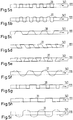
- Fig. 5a to 5i are exemplary curves of wave-like elongated elements shown, which are formed by a Vorstichnaht by a substrate layer 111. The structural level can be seen in each case.
Landscapes
- Business, Economics & Management (AREA)
- Accounting & Taxation (AREA)
- Finance (AREA)
- Health & Medical Sciences (AREA)
- General Health & Medical Sciences (AREA)
- Toxicology (AREA)
- Physics & Mathematics (AREA)
- General Physics & Mathematics (AREA)
- Inspection Of Paper Currency And Valuable Securities (AREA)
- Credit Cards Or The Like (AREA)
Claims (13)
- Procédé de fabrication d'un document de sécurité (1) comprenant les étapes suivantes :la préparation d'au moins une couche de substrat (111) d'étendue plane ;la réalisation d'un joint de type piqûre (150) avec un élément allongé (31) conducteur de sorte que le joint de type piqûre pénètre dans l'au moins une couche de substrat d'une face supérieure de la couche de substrat (111) à une face inférieure de la couche de substrat (111) et inversement, et plusieurs sections de l'élément allongé (31) pénétrant dans l'au moins une couche de substrat (111) transversalement à l'étendue plane de celle-ci sont conductrices et lesquelles peuvent être excitées au moyen d'un rayonnement à micro-ondes polarisé linéairement et dirigé le long d'une première direction spatiale, qui est orientée parallèlement à la direction d'extension longitudinale (35) de l'élément allongé (31) conducteur, de sorte que l'élément allongé (31) formant le joint de type piqûre réémet lui-même le rayonnement à micro-ondes dans une seconde direction spatiale qui est orientée transversalement à la direction de la polarisation et à la première direction spatiale, dans lequel l'orientation de la polarisation du rayonnement à micro-ondes d'excitation indique la direction dans l'espace parallèlement à laquelle oscille le vecteur de champ électrique du rayonnement à micro-ondes d'excitation.
- Procédé selon la revendication 1, caractérisé en ce que le joint est exécuté avec au moins un brin présentant un fil métallique ou un fil métallique en tant qu'élément allongé (31).
- Procédé selon la revendication 1 ou 2, caractérisé en ce que le joint (150) est exécuté avec une longueur de piqûre constante.
- Procédé selon l'une quelconque des revendications 1 à 3, caractérisé en ce que la couche de substrat (111) pourvue du joint de type piqûre est assemblée avec d'autres couches de substrat (161 à 163) d'étendue plane pour former un corps de document (3).
- Procédé selon la revendication 4, caractérisé en ce que la couche de substrat avec le joint est disposée lors de l'assemblage entre deux des couches de substrat d'étendue plane.
- Procédé selon l'une quelconque des revendications 1 à 5, caractérisé en ce qu'une autre structure conductrice de forme ondulée est appliquée sur la couche de substrat ou sur une des autres couches de substrat.
- Document de sécurité avec un corps de document réalisé de manière plane qui présente une face supérieure et une face inférieure opposée et contre lequel ou dans lequel est disposé un élément allongé (31) conducteur réalisé de manière ondulée, dans lequel l'élément allongé présente des déformations de forme ondulée (33) qui sont orientées transversalement à une direction d'extension longitudinale (35) de l'élément allongé (31) et transversalement à l'étendue plane du corps de document (3), dans lequel les déformations de forme ondulée pénètrent dans au moins une couche matérielle du corps de document transversalement à l'étendue plane de celle-ci et peuvent être excitées au moyen d'un rayonnement à micro-ondes polarisé linéairement et dirigé le long d'une première direction spatiale qui est orientée parallèlement à la direction d'extension longitudinale (35) de l'élément allongé (31) de sorte que l'élément allongé (31) conducteur réalisé de manière ondulée réémet lui-même le rayonnement à micro-ondes dans une seconde direction spatiale qui est orientée transversalement à la direction de la polarisation et à la première direction spatiale, dans lequel la direction de la polarisation du rayonnement à micro-ondes indique la direction dans l'espace parallèle à laquelle oscille le vecteur de champ électrique du rayonnement à micro-ondes d'excitation.
- Document de sécurité selon la revendication 7, caractérisé en ce que la conception de forme ondulée de l'élément allongé présente une périodicité.
- Document de sécurité selon l'une quelconque des revendications 7 ou 8, caractérisé en ce que, sur ou dans le corps de document (3) est réalisée une autre structure conductrice de forme ondulée (41) qui s'étend dans un plan (44) qui est orienté parallèlement à l'extension plane du corps de document (3).
- Document de sécurité selon les revendications 8 à 9, caractérisé en ce que l'autre structure conductrice de forme ondulée (41) est une structure périodique qui présente une autre longueur de période que la structure de l'élément allongé (31).
- Dispositif (200) de vérification d'un document de sécurité (1) avec un corps de document réalisé de manière plane contre lequel ou dans lequel est disposé un élément allongé conducteur réalisé de manière ondulée, dans lequel des déformations de forme ondulée sont orientées transversalement à une direction d'extension longitudinale de l'élément allongé et transversalement à une étendue plane du corps de document, comprenant :un émetteur à micro-ondes (201) destiné à émettre un rayonnement à micro-ondes polarisé linéairement le long d'une première direction spatiale dans une région d'examen (100) qui est réalisée pour recevoir un document de sécurité de sorte que la première direction spatiale coïncide avec un plan dans lequel le corps de document s'étend de manière plane,et un récepteur à micro-ondes qui est conçu pour recevoir de la région d'examen un rayonnement à micro-ondes émis le long d'une seconde direction spatiale, dans lequel la seconde direction spatiale est orientée transversalement à la première direction spatiale et transversalement à la direction de la polarisation du rayonnement à micro-ondes polarisé linéairement émis par l'émetteur à micro-ondes (201), etun système de commande pour provoquer un rayonnement à micro-ondes de l'émetteur à micro-ondes et pour détecter simultanément un signal de réception du récepteur à micro-ondes et un système d'évaluation destiné à générer un signal de vérification qui est déduit du signal de réception.
- Procédé de vérification d'un document de sécurité (1) comprenant les étapes suivantes :la disposition d'un document de sécurité dans une région d'examen de sorte qu'une première direction spatiale coïncide avec un plan dans lequel un corps de document du document de sécurité (1) s'étend de manière plane ;l'émission d'un rayonnement à micro-ondes polarisé linéairement (51) le long de la première direction spatiale dans la région d'examen (100) etla détection d'un rayonnement à micro-ondes (71) qui sort de la région d'examen (100),et l'évaluation du rayonnement à micro-ondes détecté et la déduction d'une décision de vérification, caractérisé en ce que, lors de la détection du rayonnement à micro-ondes (71), un rayonnement à micro-ondes est détecté le long d'une seconde direction spatiale, dans lequel la seconde direction spatiale est orientée transversalement à la première direction spatiale et transversalement à la direction d'oscillation du vecteur de champ électrique du rayonnement à micro-ondes polarisé linéairement émis.
- Procédé selon la revendication 12, caractérisé en ce qu'un document (1) est vérifié en tant qu'authentique lorsqu'une intensité de signal prédéfinie est détectée dans le récepteur à micro-ondes (221).
Applications Claiming Priority (2)
| Application Number | Priority Date | Filing Date | Title |
|---|---|---|---|
| DE102013203758.9A DE102013203758B4 (de) | 2013-03-05 | 2013-03-05 | Sicherheitsdokument mit mittels Mikrowellen verifizierbarem Sicherheitselement |
| PCT/EP2014/054281 WO2014135597A1 (fr) | 2013-03-05 | 2014-03-05 | Document de sécurité comportant un élément de sécurité pouvant être authentifié au moyen de micro-ondes |
Publications (2)
| Publication Number | Publication Date |
|---|---|
| EP2964470A1 EP2964470A1 (fr) | 2016-01-13 |
| EP2964470B1 true EP2964470B1 (fr) | 2017-06-14 |
Family
ID=50236172
Family Applications (1)
| Application Number | Title | Priority Date | Filing Date |
|---|---|---|---|
| EP14708249.9A Active EP2964470B1 (fr) | 2013-03-05 | 2014-03-05 | Document de sécurité comportant un élément de sécurité pouvant être authentifié au moyen de micro-ondes |
Country Status (3)
| Country | Link |
|---|---|
| EP (1) | EP2964470B1 (fr) |
| DE (1) | DE102013203758B4 (fr) |
| WO (1) | WO2014135597A1 (fr) |
Family Cites Families (7)
| Publication number | Priority date | Publication date | Assignee | Title |
|---|---|---|---|---|
| FR2425937A1 (fr) * | 1978-05-17 | 1979-12-14 | Arjomari Prioux | Structure fibreuse contenant des fibres metalliques, son procede de preparation, et son application notamment dans l'industrie du papier |
| LU84307A1 (fr) * | 1982-07-29 | 1984-03-22 | Bekaert Sa Nv | Systeme pour l'identification d'articles en feuilles par micro-ondes |
| US5279403A (en) * | 1992-07-23 | 1994-01-18 | Crane & Company, Inc. | Microwave security thread detector |
| AU7150196A (en) * | 1996-09-23 | 1998-04-14 | Petrik, Victor Ivanovich | Method and system for protection against counterfeiting of titles and documents |
| DE102004043064A1 (de) * | 2004-09-06 | 2006-03-09 | Giesecke & Devrient Gmbh | Sicherheitselement mit maschinenlesbarem Echtheitsmerkmal |
| EP1923822A1 (fr) * | 2006-11-09 | 2008-05-21 | Gemplus | Procédé de réalisation d'un élément de circuit électrique ou électronique sécurisé, élément obtenu et support intégrant ledit élément |
| DE102006055680A1 (de) * | 2006-11-23 | 2008-05-29 | Giesecke & Devrient Gmbh | Sicherheitselement mit Metallisierung |
-
2013
- 2013-03-05 DE DE102013203758.9A patent/DE102013203758B4/de active Active
-
2014
- 2014-03-05 EP EP14708249.9A patent/EP2964470B1/fr active Active
- 2014-03-05 WO PCT/EP2014/054281 patent/WO2014135597A1/fr not_active Ceased
Also Published As
| Publication number | Publication date |
|---|---|
| EP2964470A1 (fr) | 2016-01-13 |
| DE102013203758B4 (de) | 2019-05-16 |
| DE102013203758A1 (de) | 2014-09-11 |
| WO2014135597A1 (fr) | 2014-09-12 |
Similar Documents
| Publication | Publication Date | Title |
|---|---|---|
| DE19812812A1 (de) | Aufbau von Sicherheitselementen für Dokumente und Vorrichtungen zur Prüfung von Dokumenten mit derartigen Sicherheitselementen sowie Verfahren zur Anwendung | |
| EP2066836A1 (fr) | Étiquettes rfid destinées aux articles textiles | |
| EP1328899B1 (fr) | Procede de fabrication d'une bobine de transpondeur | |
| DE19903988B4 (de) | Vorrichtung zur Validierung von Echtheitsmerkmalen auf Wert- und Sicherheitsdokumenten | |
| EP1792283B1 (fr) | Element de securite comprenant une caracteristique d'authenticite lisible par machine | |
| EP2964470B1 (fr) | Document de sécurité comportant un élément de sécurité pouvant être authentifié au moyen de micro-ondes | |
| DE19734855B4 (de) | Vorrichtung zur Prüfung beugungsoptisch wirksamer Sicherheitselemente | |
| EP3511152B1 (fr) | Essai de qualité d'un assemblage soudé par ultrasons | |
| EP1363233A1 (fr) | Document de sécurité munis d'un circuit résonant | |
| EP0698866A1 (fr) | Machines à essayer et méthode pour essayer des documents dans une machine à usiner | |
| DE102004042187B4 (de) | Chipkartenmodul für eine kontaklose Chipkarte mit Sicherheitsmarkierung | |
| EP0978108A2 (fr) | Utilisation et procede pour le controle de documents a couches de securite diffringentes | |
| DE102009034896B4 (de) | Sicherheitsdokument und Verfahren zur Herstellung eines Sicherheitsdokumentes | |
| DE3327450A1 (de) | Verfahren und geraet zum identifizieren flaechiger gegenstaende mit hilfe von mikrowellen i | |
| DE19512921A1 (de) | Einrichtung zur Prüfung von Sicherheitsdokumenten | |
| EP3261064B1 (fr) | Document d'authentification | |
| EP3079917A1 (fr) | Document de sécurité doté d'un système de contrôle d'un circuit et procédé de contrôle d'un circuit dans un document de sécurité | |
| EP2976680B1 (fr) | Procédé et dispositif pour exciter sans contact des pigments électroluminescents | |
| DE102024209232A1 (de) | Authentifizierungsvorrichtung, authentifizierungsvorrichtungs-anordnung und authentifizierungsgerät | |
| EP1002300A1 (fr) | Structure d'elements de securite pour documents, dispositifs pour le controle de documents comportant de tels elements de securite, et procede d'utilisation de ces elements de securite et dispositifs | |
| EP4650182A1 (fr) | Document avec une caractéristique de sécurité | |
| DE102005021815A1 (de) | Sicherheitsmerkmal und Gerät zum Überprüfen des Sicherheitsmerkmals | |
| WO2002080117A2 (fr) | Procede de verification | |
| DE102016013331A1 (de) | Dokumententräger, Verfahren zu dessen Verifikation und Verifikationsvorrichtung zur Durchführung des Verfahrens | |
| CH707541A2 (de) | Sicherheitselement für Wertpapiere und Dokumente sowie Verfahren zu dessen Herstellung. |
Legal Events
| Date | Code | Title | Description |
|---|---|---|---|
| PUAI | Public reference made under article 153(3) epc to a published international application that has entered the european phase |
Free format text: ORIGINAL CODE: 0009012 |
|
| 17P | Request for examination filed |
Effective date: 20150831 |
|
| AK | Designated contracting states |
Kind code of ref document: A1 Designated state(s): AL AT BE BG CH CY CZ DE DK EE ES FI FR GB GR HR HU IE IS IT LI LT LU LV MC MK MT NL NO PL PT RO RS SE SI SK SM TR |
|
| AX | Request for extension of the european patent |
Extension state: BA ME |
|
| DAX | Request for extension of the european patent (deleted) | ||
| GRAP | Despatch of communication of intention to grant a patent |
Free format text: ORIGINAL CODE: EPIDOSNIGR1 |
|
| INTG | Intention to grant announced |
Effective date: 20170109 |
|
| GRAS | Grant fee paid |
Free format text: ORIGINAL CODE: EPIDOSNIGR3 |
|
| GRAA | (expected) grant |
Free format text: ORIGINAL CODE: 0009210 |
|
| AK | Designated contracting states |
Kind code of ref document: B1 Designated state(s): AL AT BE BG CH CY CZ DE DK EE ES FI FR GB GR HR HU IE IS IT LI LT LU LV MC MK MT NL NO PL PT RO RS SE SI SK SM TR |
|
| REG | Reference to a national code |
Ref country code: GB Ref legal event code: FG4D Free format text: NOT ENGLISH |
|
| REG | Reference to a national code |
Ref country code: CH Ref legal event code: EP Ref country code: AT Ref legal event code: REF Ref document number: 900572 Country of ref document: AT Kind code of ref document: T Effective date: 20170615 |
|
| REG | Reference to a national code |
Ref country code: IE Ref legal event code: FG4D Free format text: LANGUAGE OF EP DOCUMENT: GERMAN |
|
| REG | Reference to a national code |
Ref country code: DE Ref legal event code: R096 Ref document number: 502014004193 Country of ref document: DE |
|
| REG | Reference to a national code |
Ref country code: NL Ref legal event code: MP Effective date: 20170614 |
|
| REG | Reference to a national code |
Ref country code: LT Ref legal event code: MG4D |
|
| PG25 | Lapsed in a contracting state [announced via postgrant information from national office to epo] |
Ref country code: GR Free format text: LAPSE BECAUSE OF FAILURE TO SUBMIT A TRANSLATION OF THE DESCRIPTION OR TO PAY THE FEE WITHIN THE PRESCRIBED TIME-LIMIT Effective date: 20170915 Ref country code: NO Free format text: LAPSE BECAUSE OF FAILURE TO SUBMIT A TRANSLATION OF THE DESCRIPTION OR TO PAY THE FEE WITHIN THE PRESCRIBED TIME-LIMIT Effective date: 20170914 Ref country code: LT Free format text: LAPSE BECAUSE OF FAILURE TO SUBMIT A TRANSLATION OF THE DESCRIPTION OR TO PAY THE FEE WITHIN THE PRESCRIBED TIME-LIMIT Effective date: 20170614 Ref country code: HR Free format text: LAPSE BECAUSE OF FAILURE TO SUBMIT A TRANSLATION OF THE DESCRIPTION OR TO PAY THE FEE WITHIN THE PRESCRIBED TIME-LIMIT Effective date: 20170614 Ref country code: FI Free format text: LAPSE BECAUSE OF FAILURE TO SUBMIT A TRANSLATION OF THE DESCRIPTION OR TO PAY THE FEE WITHIN THE PRESCRIBED TIME-LIMIT Effective date: 20170614 |
|
| PG25 | Lapsed in a contracting state [announced via postgrant information from national office to epo] |
Ref country code: SE Free format text: LAPSE BECAUSE OF FAILURE TO SUBMIT A TRANSLATION OF THE DESCRIPTION OR TO PAY THE FEE WITHIN THE PRESCRIBED TIME-LIMIT Effective date: 20170614 Ref country code: RS Free format text: LAPSE BECAUSE OF FAILURE TO SUBMIT A TRANSLATION OF THE DESCRIPTION OR TO PAY THE FEE WITHIN THE PRESCRIBED TIME-LIMIT Effective date: 20170614 Ref country code: NL Free format text: LAPSE BECAUSE OF FAILURE TO SUBMIT A TRANSLATION OF THE DESCRIPTION OR TO PAY THE FEE WITHIN THE PRESCRIBED TIME-LIMIT Effective date: 20170614 Ref country code: LV Free format text: LAPSE BECAUSE OF FAILURE TO SUBMIT A TRANSLATION OF THE DESCRIPTION OR TO PAY THE FEE WITHIN THE PRESCRIBED TIME-LIMIT Effective date: 20170614 Ref country code: BG Free format text: LAPSE BECAUSE OF FAILURE TO SUBMIT A TRANSLATION OF THE DESCRIPTION OR TO PAY THE FEE WITHIN THE PRESCRIBED TIME-LIMIT Effective date: 20170914 |
|
| PG25 | Lapsed in a contracting state [announced via postgrant information from national office to epo] |
Ref country code: CZ Free format text: LAPSE BECAUSE OF FAILURE TO SUBMIT A TRANSLATION OF THE DESCRIPTION OR TO PAY THE FEE WITHIN THE PRESCRIBED TIME-LIMIT Effective date: 20170614 Ref country code: EE Free format text: LAPSE BECAUSE OF FAILURE TO SUBMIT A TRANSLATION OF THE DESCRIPTION OR TO PAY THE FEE WITHIN THE PRESCRIBED TIME-LIMIT Effective date: 20170614 Ref country code: SK Free format text: LAPSE BECAUSE OF FAILURE TO SUBMIT A TRANSLATION OF THE DESCRIPTION OR TO PAY THE FEE WITHIN THE PRESCRIBED TIME-LIMIT Effective date: 20170614 Ref country code: RO Free format text: LAPSE BECAUSE OF FAILURE TO SUBMIT A TRANSLATION OF THE DESCRIPTION OR TO PAY THE FEE WITHIN THE PRESCRIBED TIME-LIMIT Effective date: 20170614 |
|
| PG25 | Lapsed in a contracting state [announced via postgrant information from national office to epo] |
Ref country code: IS Free format text: LAPSE BECAUSE OF FAILURE TO SUBMIT A TRANSLATION OF THE DESCRIPTION OR TO PAY THE FEE WITHIN THE PRESCRIBED TIME-LIMIT Effective date: 20171014 Ref country code: SM Free format text: LAPSE BECAUSE OF FAILURE TO SUBMIT A TRANSLATION OF THE DESCRIPTION OR TO PAY THE FEE WITHIN THE PRESCRIBED TIME-LIMIT Effective date: 20170614 Ref country code: ES Free format text: LAPSE BECAUSE OF FAILURE TO SUBMIT A TRANSLATION OF THE DESCRIPTION OR TO PAY THE FEE WITHIN THE PRESCRIBED TIME-LIMIT Effective date: 20170614 Ref country code: IT Free format text: LAPSE BECAUSE OF FAILURE TO SUBMIT A TRANSLATION OF THE DESCRIPTION OR TO PAY THE FEE WITHIN THE PRESCRIBED TIME-LIMIT Effective date: 20170614 Ref country code: PL Free format text: LAPSE BECAUSE OF FAILURE TO SUBMIT A TRANSLATION OF THE DESCRIPTION OR TO PAY THE FEE WITHIN THE PRESCRIBED TIME-LIMIT Effective date: 20170614 |
|
| REG | Reference to a national code |
Ref country code: DE Ref legal event code: R097 Ref document number: 502014004193 Country of ref document: DE |
|
| REG | Reference to a national code |
Ref country code: FR Ref legal event code: PLFP Year of fee payment: 5 |
|
| PLBE | No opposition filed within time limit |
Free format text: ORIGINAL CODE: 0009261 |
|
| STAA | Information on the status of an ep patent application or granted ep patent |
Free format text: STATUS: NO OPPOSITION FILED WITHIN TIME LIMIT |
|
| PG25 | Lapsed in a contracting state [announced via postgrant information from national office to epo] |
Ref country code: DK Free format text: LAPSE BECAUSE OF FAILURE TO SUBMIT A TRANSLATION OF THE DESCRIPTION OR TO PAY THE FEE WITHIN THE PRESCRIBED TIME-LIMIT Effective date: 20170614 |
|
| 26N | No opposition filed |
Effective date: 20180315 |
|
| PG25 | Lapsed in a contracting state [announced via postgrant information from national office to epo] |
Ref country code: SI Free format text: LAPSE BECAUSE OF FAILURE TO SUBMIT A TRANSLATION OF THE DESCRIPTION OR TO PAY THE FEE WITHIN THE PRESCRIBED TIME-LIMIT Effective date: 20170614 |
|
| PG25 | Lapsed in a contracting state [announced via postgrant information from national office to epo] |
Ref country code: MT Free format text: LAPSE BECAUSE OF FAILURE TO SUBMIT A TRANSLATION OF THE DESCRIPTION OR TO PAY THE FEE WITHIN THE PRESCRIBED TIME-LIMIT Effective date: 20170614 |
|
| REG | Reference to a national code |
Ref country code: CH Ref legal event code: PL |
|
| PG25 | Lapsed in a contracting state [announced via postgrant information from national office to epo] |
Ref country code: MC Free format text: LAPSE BECAUSE OF FAILURE TO SUBMIT A TRANSLATION OF THE DESCRIPTION OR TO PAY THE FEE WITHIN THE PRESCRIBED TIME-LIMIT Effective date: 20170614 |
|
| REG | Reference to a national code |
Ref country code: BE Ref legal event code: MM Effective date: 20180331 |
|
| REG | Reference to a national code |
Ref country code: IE Ref legal event code: MM4A |
|
| PG25 | Lapsed in a contracting state [announced via postgrant information from national office to epo] |
Ref country code: LU Free format text: LAPSE BECAUSE OF NON-PAYMENT OF DUE FEES Effective date: 20180305 |
|
| PG25 | Lapsed in a contracting state [announced via postgrant information from national office to epo] |
Ref country code: IE Free format text: LAPSE BECAUSE OF NON-PAYMENT OF DUE FEES Effective date: 20180305 |
|
| PG25 | Lapsed in a contracting state [announced via postgrant information from national office to epo] |
Ref country code: LI Free format text: LAPSE BECAUSE OF NON-PAYMENT OF DUE FEES Effective date: 20180331 Ref country code: CH Free format text: LAPSE BECAUSE OF NON-PAYMENT OF DUE FEES Effective date: 20180331 Ref country code: BE Free format text: LAPSE BECAUSE OF NON-PAYMENT OF DUE FEES Effective date: 20180331 |
|
| PG25 | Lapsed in a contracting state [announced via postgrant information from national office to epo] |
Ref country code: TR Free format text: LAPSE BECAUSE OF FAILURE TO SUBMIT A TRANSLATION OF THE DESCRIPTION OR TO PAY THE FEE WITHIN THE PRESCRIBED TIME-LIMIT Effective date: 20170614 |
|
| PG25 | Lapsed in a contracting state [announced via postgrant information from national office to epo] |
Ref country code: PT Free format text: LAPSE BECAUSE OF FAILURE TO SUBMIT A TRANSLATION OF THE DESCRIPTION OR TO PAY THE FEE WITHIN THE PRESCRIBED TIME-LIMIT Effective date: 20170614 |
|
| PG25 | Lapsed in a contracting state [announced via postgrant information from national office to epo] |
Ref country code: CY Free format text: LAPSE BECAUSE OF FAILURE TO SUBMIT A TRANSLATION OF THE DESCRIPTION OR TO PAY THE FEE WITHIN THE PRESCRIBED TIME-LIMIT Effective date: 20170614 Ref country code: MK Free format text: LAPSE BECAUSE OF NON-PAYMENT OF DUE FEES Effective date: 20170614 Ref country code: HU Free format text: LAPSE BECAUSE OF FAILURE TO SUBMIT A TRANSLATION OF THE DESCRIPTION OR TO PAY THE FEE WITHIN THE PRESCRIBED TIME-LIMIT; INVALID AB INITIO Effective date: 20140305 |
|
| PG25 | Lapsed in a contracting state [announced via postgrant information from national office to epo] |
Ref country code: AL Free format text: LAPSE BECAUSE OF FAILURE TO SUBMIT A TRANSLATION OF THE DESCRIPTION OR TO PAY THE FEE WITHIN THE PRESCRIBED TIME-LIMIT Effective date: 20170614 |
|
| REG | Reference to a national code |
Ref country code: AT Ref legal event code: MM01 Ref document number: 900572 Country of ref document: AT Kind code of ref document: T Effective date: 20190305 |
|
| PG25 | Lapsed in a contracting state [announced via postgrant information from national office to epo] |
Ref country code: AT Free format text: LAPSE BECAUSE OF NON-PAYMENT OF DUE FEES Effective date: 20190305 |
|
| P01 | Opt-out of the competence of the unified patent court (upc) registered |
Effective date: 20230526 |
|
| PGFP | Annual fee paid to national office [announced via postgrant information from national office to epo] |
Ref country code: GB Payment date: 20260324 Year of fee payment: 13 |
|
| PGFP | Annual fee paid to national office [announced via postgrant information from national office to epo] |
Ref country code: DE Payment date: 20260320 Year of fee payment: 13 |
|
| PGFP | Annual fee paid to national office [announced via postgrant information from national office to epo] |
Ref country code: FR Payment date: 20260324 Year of fee payment: 13 |