EP2964862B1 - Verfahren zur befestigung eines blendrahmens an einem mauerwerk mit einem dübelkammeradapter - Google Patents
Verfahren zur befestigung eines blendrahmens an einem mauerwerk mit einem dübelkammeradapter Download PDFInfo
- Publication number
- EP2964862B1 EP2964862B1 EP14709267.0A EP14709267A EP2964862B1 EP 2964862 B1 EP2964862 B1 EP 2964862B1 EP 14709267 A EP14709267 A EP 14709267A EP 2964862 B1 EP2964862 B1 EP 2964862B1
- Authority
- EP
- European Patent Office
- Prior art keywords
- frame profile
- window frame
- dowel
- chamber adapter
- adapter
- Prior art date
- Legal status (The legal status is an assumption and is not a legal conclusion. Google has not performed a legal analysis and makes no representation as to the accuracy of the status listed.)
- Active
Links
Images
Classifications
-
- E—FIXED CONSTRUCTIONS
- E06—DOORS, WINDOWS, SHUTTERS, OR ROLLER BLINDS IN GENERAL; LADDERS
- E06B—FIXED OR MOVABLE CLOSURES FOR OPENINGS IN BUILDINGS, VEHICLES, FENCES OR LIKE ENCLOSURES IN GENERAL, e.g. DOORS, WINDOWS, BLINDS, GATES
- E06B1/00—Border constructions of openings in walls, floors, or ceilings; Frames to be rigidly mounted in such openings
- E06B1/56—Fastening frames to the border of openings or to similar contiguous frames
- E06B1/60—Fastening frames to the border of openings or to similar contiguous frames by mechanical means, e.g. anchoring means
-
- E—FIXED CONSTRUCTIONS
- E06—DOORS, WINDOWS, SHUTTERS, OR ROLLER BLINDS IN GENERAL; LADDERS
- E06B—FIXED OR MOVABLE CLOSURES FOR OPENINGS IN BUILDINGS, VEHICLES, FENCES OR LIKE ENCLOSURES IN GENERAL, e.g. DOORS, WINDOWS, BLINDS, GATES
- E06B3/00—Window sashes, door leaves, or like elements for closing wall or like openings; Layout of fixed or moving closures, e.g. windows in wall or like openings; Features of rigidly-mounted outer frames relating to the mounting of wing frames
- E06B3/04—Wing frames not characterised by the manner of movement
- E06B3/06—Single frames
- E06B3/08—Constructions depending on the use of specified materials
- E06B3/20—Constructions depending on the use of specified materials of plastics
- E06B3/22—Hollow frames
- E06B3/221—Hollow frames with the frame member having local reinforcements in some parts of its cross-section or with a filled cavity
- E06B3/222—Hollow frames with the frame member having local reinforcements in some parts of its cross-section or with a filled cavity with internal prefabricated reinforcing section members inserted after manufacturing of the hollow frame
-
- F—MECHANICAL ENGINEERING; LIGHTING; HEATING; WEAPONS; BLASTING
- F16—ENGINEERING ELEMENTS AND UNITS; GENERAL MEASURES FOR PRODUCING AND MAINTAINING EFFECTIVE FUNCTIONING OF MACHINES OR INSTALLATIONS; THERMAL INSULATION IN GENERAL
- F16B—DEVICES FOR FASTENING OR SECURING CONSTRUCTIONAL ELEMENTS OR MACHINE PARTS TOGETHER, e.g. NAILS, BOLTS, CIRCLIPS, CLAMPS, CLIPS OR WEDGES; JOINTS OR JOINTING
- F16B43/00—Washers or equivalent devices; Other devices for supporting bolt-heads or nuts
- F16B43/02—Washers or equivalent devices; Other devices for supporting bolt-heads or nuts with special provisions for engaging surfaces which are not perpendicular to a bolt axis or do not surround the bolt
- F16B43/025—Washers or equivalent devices; Other devices for supporting bolt-heads or nuts with special provisions for engaging surfaces which are not perpendicular to a bolt axis or do not surround the bolt for surfaces not surrounding the bolt, e.g. hook adaptors for bolts
Definitions
- the invention relates to a method for fixing a hollow-walled frame profile to a masonry o.
- the like With a Dübelzigadapter.
- Windows and doors are to a large extent made of hollow profile profiles of thermoplastic material, in particular PVC.
- the frame profiles usually have a large hollow chamber for receiving a steel reinforcement - also called steel chamber - on.
- Some profile systems also provide for the screwing of the frame in masonry a separate, separate from the steel chamber through a wall anchor chamber. As far as the screw is guided exclusively through this dowel chamber, it is ensured that no moisture can get into the steel chamber. As far as such a dowel chamber is not provided or if the screwing of the frame is to be performed by the steel chamber for other reasons, there is a risk when mounting the window frame in the masonry that driving rain, which can reach into the rebate, in the screw in the Steel chamber and from there possibly even enters the masonry and leads to damage in the masonry and corrosion of the steel reinforcement.
- Object of the present invention is to accomplish a screwing of a frame through the rebate area in an adjacent masonry so that even with the ingress of water in the rebate area of the frame secure sealing of the rebate area against the hollow chambers of the frame profile is guaranteed.
- Another concern of the invention is to simplify the mounting of a window frame in a wall opening.
- the invention achieves this object by a method according to claim 1, preferably in conjunction with one or more of the features of the subclaims.
- the dowel chamber adapter used according to the invention has a base body with an underside, an upper side and a bore penetrating the base body, a pin arranged at a distance from the base body and a means arranged on the lower side of the base body for sealing the dowel chamber adapter with respect to the window frame profile.
- the hole serves to guide a screw through the frame in the masonry.
- the pin serves to be clamped or snapped into a space in the folding frame of the frame profile space inside limiting Glasologicalningnut. As a result, a defined distance of the screw to the Glazing bead receiving groove and thus secured to the inside edge of the frame profile.
- the arranged on the underside of the body means for sealing the dowel chamber adapter relative to the frame profile ensures that driving rain or other moisture that enters the rebate area of the frame, can not penetrate through the screw into the steel chamber or masonry.
- the dowel chamber adapter thus replaces a separate dowel chamber in terms of its function.
- the dowel chamber adapter used in accordance with the invention is preferably produced from metal by die-casting or alternatively from plastic by injection molding.
- the Dübelzigadapter is made of plastic by injection molding
- the sealing of Dübelzigadapter relative to the frame preferably made of soft elastic plastic, which is connected in one piece with the body according to a particularly preferred embodiment of the invention in the so-called two-component injection molding.
- a sealing cushion made of foam is used as means for sealing the dowel chamber adapter relative to the frame profile a sealing cushion made of foam.
- this is closed-cell foam.
- This variant is particularly suitable for Dübelhuntadapter made of metal.
- the anchor chamber adapter comprises means for clamping or locking the pin in the glazing bead receiving groove of the frame profile.
- This may be, for example, a molded-on small cam, a nose or an undercut of the pin.
- the dowel chamber adapter according to the invention is used in a system which, in addition to the dowel-chamber adapter, has a window frame profile with a folding area, an outer side, an inner side and a in the region of the inside of the rebate bounding Glaselfnfactnut.
- a window frame profile with a folding area, an outer side, an inner side and a in the region of the inside of the rebate bounding Glaselfnfactnut.
- the dowel chamber adapter according to the invention in a window frame, wherein the fold region of the frame profile has a flat, when used properly horizontally and thus perpendicular to the inside extending portion extending from the Glasologicalnabilitynut toward the outside, as in such a frame
- the system used is preferably an abutment sealing system.
- the dowel chamber adapter is first fastened by clamping or latching insertion of the pin into the glazing bead receiving groove in the rebate area of the window frame profile. Then, if necessary after appropriate pre-drilling, a screw through the dowel chamber adapter and the frame profile screwed into the wall of the wall opening, the head of the screw sunk in Dübelhuntadapter and the means for sealing under compression of the dowel chamber adapter is pressed against the frame profile.
- a hole is drilled through the frame profile in the wall of the wall opening before screwing the screw using the anchor chamber adapter as a drilling jig for pre-drilling.
- Dübel screeningadapter 1 consists essentially of the main body 8 and a spaced from the base 8 pin 9, wherein the pin 9 at the top of Dübel screeningadapters 1 - viewed in cross section - a narrow web with the Main body 8 is connected.
- the dowel chamber adapter 1 shown was produced by die casting from a zinc alloy.
- a sealing pad 2 made of waterproof, closed-cell sponge rubber is glued (see also Fig. 6 ).
- the main body 8 is made of plastic, may alternatively be used as a means for sealing the base body 8 relative to the frame profile 3 also integrally connected to the main body 8 seal made of soft elastic material.
- the dowel chamber adapter 1 is clipped with the pin 9 in the Glasancenfactnut 10, wherein the clamping cam 13 ensures a secure clamping or Verklipsung in Glasarchnfactnut 10.
- frame profile 4 is a hollow chamber profile that can be used either for a center seal or stop seal system. When used as a stop seal system, the center seal receiving groove is covered in the Blendrahmenfalz Scheme by a piping. For holding a steel reinforcement - in Fig. 1 not shown - serves the hollow chamber eleventh
- Fig. 1 is good to see that the fold region 7 of the frame 4, starting from the glazing bead receiving groove 10 in a flat area and horizontal, ie perpendicular to the inside 4 runs.
- the risk that driving rain reaches the glazing area receiving groove 10 in the folding area 7 is particularly high.
- the frame profile 3 does not have a separate dowel chamber, so that the screw 12 is guided through the acting as a steel chamber hollow chamber 11.
Landscapes
- Engineering & Computer Science (AREA)
- Civil Engineering (AREA)
- Structural Engineering (AREA)
- Mechanical Engineering (AREA)
- General Engineering & Computer Science (AREA)
- Door And Window Frames Mounted To Openings (AREA)
Description
- Die Erfindung betrifft Verfahren zur Befestigung eines Hohlkammern aufweisenden Blendrahmenprofils an einem Mauerwerk o. dgl. mit einem Dübelkammeradapter.
- Fenster und Türen werden in großem Umfang aus Hohlkammerprofilen aus thermoplastischem Kunststoff, insbesondere aus PVC, hergestellt. Zur Versteifung weisen die Blendrahmenprofile üblicherweise eine groß dimensionierte Hohlkammer zur Aufnahme einer Stahlverstärkung - auch Stahlkammer genannt - auf.
- Einige Profilsysteme sehen für die Verschraubung des Blendrahmens im Mauerwerk auch eine gesonderte, von der Stahlkammer durch eine Wandung getrennte Dübelkammer vor. Soweit die Verschraubung ausschließlich durch diese Dübelkammer geführt wird, ist sichergestellt, dass keine Feuchtigkeit in die Stahlkammer gelangen kann. Soweit eine solche Dübelkammer nicht vorgesehen ist oder wenn aus anderen Gründen die Verschraubung des Blendrahmens durch die Stahlkammer geführt werden soll, besteht beim Befestigen des Blendrahmens im Mauerwerk die Gefahr, dass Schlagregen, der bis in den Falzbereich gelangen kann, im Bereich der Verschraubung in die Stahlkammer und von dort ggf. sogar in das Mauerwerk gelangt und zu Schäden im Mauerwerk und zur Korrosion der Stahlverstärkung führt.
- Besonders problematisch ist diese Situation bei sogenannten Anschlagdichtungssystemen, und ganz besonders bei solchen Anschlagdichtungssystemen, die einen flachen oder gar horizontal verlaufenden Blendrahmenfalzbereich aufweisen. Es besteht bei solchen Systemen dann die Notwendigkeit, die Verschraubung aufwändig beispielsweise mit Silikon abzudichten.
- Aus der
DE 93 01 598 U1 ist ein Kunststoffrahmen mit einem aus einem Mehrkammerprofil bestehenden Rahmenholm und einer daran im Falzbereich befestigten Außenabdeckleiste bekannt, bei dem eine Verschraubung durch eine Ausnehmung in der Außenabdeckleiste in das Mauerwerk geführt wird. Auch hier besteht die Notwendigkeit, die Verschraubung aufwändig beispielsweise mit Silikon abzudichten. - Aus der
FR 2 864 986 A1 - Es zeigt alle Merkmale des Oberbegriffs des Anspruchs 1.
- Aufgabe der vorliegenden Erfindung ist es, eine Verschraubung eines Blendrahmens durch den Falzbereich in ein angrenzendes Mauerwerk so zu bewerkstelligen, dass auch bei Eindringen von Wasser in den Falzbereich des Blendrahmens eine sichere Abdichtung des Falzbereiches gegenüber den Hohlkammern des Blendrahmenprofils gewährleistet ist. Ein weiteres Anliegen der Erfindung ist es, die Montage eines Blendrahmens in einer Maueröffnung zu vereinfachen.
- Die Erfindung löst diese Aufgabe durch ein Verfahren nach Anspruch 1, bevorzugt in Verbindung mit einem oder mehreren der Merkmale der Unteransprüche.
- Der erfindungsgemäß verwendete Dübelkammeradapter weist einen Grundkörper mit einer Unterseite, einer Oberseite und einer den Grundkörper durchdringenden Bohrung, einen vom Grundkörper beabstandet angeordneten Zapfen und ein an der Unterseite des Grundkörpers angeordnetes Mittel zur Abdichtung des Dübelkammeradapters gegenüber dem Blendrahmenprofil auf. Die Bohrung dient zur Führung einer Verschraubung durch den Blendrahmen in das Mauerwerk. Der Zapfen dient dazu, in eine den Falzbereich des Blendrahmenprofils rauminnenseitig begrenzende Glasleistenaufnahmenut eingeklemmt oder eingerastet zu werden. Hierdurch wird ein definierter Abstand der Verschraubung zur Glasleistenaufnahmenut und damit zur Innensichtkante des Blendrahmenprofils sichergestellt.
- Das an der Unterseite des Grundkörpers angeordnete Mittel zur Abdichtung des Dübelkammeradapters gegenüber dem Blendrahmenprofil stellt sicher, dass Schlagregen oder andere Feuchtigkeit, die in den Falzbereich des Blendrahmens gelangt, nicht durch die Verschraubung in die Stahlkammer oder das Mauerwerk eindringen kann. Der Dübelkammeradapter ersetzt somit von seiner Funktion her gesehen eine gesonderte Dübelkammer.
- Der erfindungsgemäß eingesetzte Dübelkammeradapter wird bevorzugt aus Metall im Druckgussverfahren oder alternativ aus Kunststoff im Spritzgussverfahren hergestellt. Soweit der Dübelkammeradapter aus Kunststoff im Spritzgussverfahren hergestellt wird, besteht die Abdichtung des Dübelkammeradapters gegenüber dem Blendrahmen bevorzugt aus weichelastischem Kunststoff, der nach einer besonders bevorzugten Ausführungsform der Erfindung im sogenannten Zweikomponenten-Spritzgussverfahren einstückig mit dem Grundkörper verbunden wird.
- Nach einer alternativen bevorzugten Ausführungsform der Erfindung wird als Mittel zur Abdichtung des Dübelkammeradapters gegenüber dem Blendrahmenprofil ein Dichtkissen aus Schaumstoff eingesetzt. Bevorzugt handelt es sich dabei um geschlossenzelligen Schaumstoff. Diese Variante eignet sich insbesondere für Dübelkammeradapter aus Metall.
- Nach einer weiteren bevorzugten Ausführungsform der Erfindung weist der erfindungsgemäße Dübelkammeradapter Mittel zum Einklemmen oder Einrasten des Zapfens in die Glasleistenaufnahmenut des Blendrahmenprofils auf. Hierbei kann es sich beispielsweise um einen angeformten kleinen Nocken, eine Nase oder eine Hinterschneidung des Zapfens handeln.
- Der erfindungsgemäße Dübelkammeradapter wird nach einer bevorzugten Ausführungsform der Erfindung in einem System eingesetzt, das neben dem Dübelkammeradapter ein Blendrahmenprofil aufweist mit einem Falzbereich, einer Außenseite, einer Innenseite und einer im Bereich der Innenseite den Falzbereich begrenzenden Glasleistenaufnahmenut. Besonders vorteilhaft ist der Einsatz des erfindungsgemäßen Dübelkammeradapters bei einem Blendrahmen, bei dem der Falzbereich des Blendrahmenprofils einen ebenen, bei bestimmungsgemäßer Verwendung horizontal und damit senkrecht zur Innenseite verlaufenden Bereich aufweist, der sich von der Glasleistenaufnahmenut in Richtung zur Außenseite erstreckt, da bei derartigen Blendrahmen eine besonders hohe Gefahr besteht, dass Schlagregen im Falzbereich bis an die Innenseite der Glasleistenaufnahmenut gelangen kann. Bevorzugt handelt es sich bei dem eingesetzten System um ein Anschlagdichtungssystem.
- Für die Befestigung eines Blendrahmens am Mauerwerk werden folgende Verfahrensschritte durchgeführt: Der Dübelkammeradapter wird zunächst durch klemmendes oder rastendes Einführen des Zapfens in die Glasleistenaufnahmenut im Falzbereich des Blendrahmenprofils befestigt. Anschließend wird, ggf. nach entsprechendem Vorbohren, eine Schraube durch den Dübelkammeradapter und das Blendrahmenprofil in die Wandung der Maueröffnung geschraubt, wobei der Kopf der Schraube im Dübelkammeradapter versenkt und das Mittel zur Abdichtung unter Abdichtung des Dübelkammeradapters gegenüber dem Blendrahmenprofil verpresst wird.
- Nach einer bevorzugten Verfahrensweise wird vor dem Eindrehen der Schraube unter Verwendung des Dübelkammeradapters als Bohrlehre zum Vorbohren ein Loch durch das Blendrahmenprofil in die Wandung der Maueröffnung gebohrt.
- Die Erfindung wird nachfolgend anhand eines Ausführungsbeispiels sowie der Zeichnung näher erläutert. Es zeigen dabei:
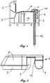
- Fig. 1
- einen Schnitt durch ein Blendrahmenprofil mit Dübelkammeradapter und Verschraubung;
- Fig. 2
- eine Seitenansicht des Dübelkammeradapters;
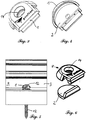
- Fig. 3
- eine Ansicht des Dübelkammeradapters von schräg oben;
- Fig. 4
- eine Ansicht des Dübelkammeradapters von schräg unten;
- Fig. 5
- eine Ansicht des Blendrahmenprofils mit Dübelkammeradapter und Verschraubung von schräg/innen;
- Fig. 6
- den Dübelkammeradapter als zweiteilige Ausführung mit Grundkörper und Dichtkissen.
- Der in
Fig. 2 in der Seitenansicht und in denFig. 3 und 4 in einer Ansicht von oben bzw. unten dargestellte erfindungsgemäße Dübelkammeradapter 1 besteht im Wesentlichen aus dem Grundkörper 8 und einem vom Grundkörper 8 beabstandet angeordneten Zapfen 9, wobei der Zapfen 9 an der Oberseite des Dübelkammeradapters 1 über - im Querschnitt betrachtet - einen schmalen Steg mit dem Grundkörper 8 verbunden ist. Der dargestellte Dübelkammeradapter 1 wurde im Druckgussverfahren aus einer Zink-Legierung hergestellt. - An der Unterseite des Dübelkammeradapters 1 ist ein Dichtkissen 2 aus wasserdichtem, geschlossenzelligem Moosgummi aufgeklebt (siehe auch
Fig. 6 ). Soweit der Grundkörper 8 aus Kunststoff besteht, kann alternativ als Mittel zur Abdichtung des Grundkörpers 8 gegenüber dem Blendrahmenprofil 3 auch eine einstückig mit dem Grundkörper 8 verbundene Dichtung aus weichelastischem Material verwendet werden. - Wie in
Fig. 1 im Querschnitt durch das Blendrahmenprofil 3 dargestellt, wird der Dübelkammeradapter 1 mit dem Zapfen 9 in die Glasleistenaufnahmenut 10 eingeklipst, wobei der Klemmnocken 13 für eine sichere Verklemmung oder Verklipsung in der Glasleistenaufnahmenut 10 sorgt. Bei dem inFig. 1 dargestellten Blendrahmenprofil 4 handelt es sich um ein Hohlkammerprofil, das wahlweise für ein Mitteldichtungs- oder Anschlagdichtungssystem eingesetzt werden kann. Beim Einsatz als Anschlagdichtungssystem wird die Mitteldichtungs-Aufnahmenut im Blendrahmenfalzbereich durch einen Keder abgedeckt. Zur Aufnahme einer Stahlverstärkung - inFig. 1 nicht dargestellt - dient die Hohlkammer 11. - In
Fig. 1 ist gut zu erkennen, dass der Falzbereich 7 des Blendrahmens 4 ausgehend von der Glasleistenaufnahmenut 10 in einem weiten Bereich eben und horizontal, also senkrecht zur Innenseite 4 verläuft. Bei derartigen Blendrahmen-Konstruktionen ist die Gefahr, dass Schlagregen in den Falzbereich 7 bis an die Glasleistenaufnahmenut 10 gelangt, besonders hoch. Zudem weist das Blendrahmenprofil 3 keine separate Dübelkammer auf, so dass die Verschraubung 12 durch die als Stahlkammer fungierende Hohlkammer 11 geführt wird. - Zur Verankerung eines Blendrahmens im Mauerwerk wird zunächst wie beschrieben der Dübelkammeradapter 1 am Blendrahmenprofil 3 verklipst. Anschließend wird unter Verwendung des Dübelkammeradapters 1 als Bohrlehre eine Bohrung durch die Hohlkammer 11 des Blendrahmenprofils 3 bis in das Mauerwerk (in den Fig. nicht dargestellt) gebohrt. Schließlich wird eine handelsübliche Schraube 12 durch den Dübelkammeradapter 1 und die Hohlkammer 11 des Blendrahmenprofils 3 bis in das Mauerwerk geschraubt, wobei zum einen der Schraubenkopf der Schraube 12 in dem Dübelkammeradapter 1 versenkt und das Dichtkissen 2 so gegen den Falzbereich 7 des Blendrahmens 3 sowie die Innenseite der Glasleistenaufnahmenut 10 verpresst wird, dass eine allseits hermetische Abdichtung des Falzbereichs 7 gegenüber der Hohlkammer 11 gewährleistet ist (
Fig. 5 ). -
- 1
- Dübelkammeradapter
- 2
- Dichtkissen
- 3
- Blendrahmenprofil
- 4
- Innenseite
- 5
- Außenseite
- 6
- Blendrahmenüberschlag
- 7
- Falzbereich
- 8
- Grundkörper
- 9
- Zapfen
- 10
- Glasleistenaufnahmenut
- 11
- Hohlkammer
- 12
- Schraube
- 13
- Klemmnocken
- 14
- Bohrung
Claims (6)
- Verfahren zur Befestigung eines Blendrahmens in einer Maueröffnung unter Verwendung eines Dübelkammeradapters (1), wobei der Dübelkammeradapters (1)- einen Grundkörper (8) mit einer Unterseite, einer Oberseite und einer den Grundkörper (8) durchdringenden Bohrung (14),- einen vom Grundkörper (8) beabstandet angeordneten Zapfen (9) und- ein an der Unterseite des Grundkörpers angeordnetes Mittel zur Abdichtung des Dübelkammeradapters (1) gegenüber dem Blendrahmenprofil (3) aufweist, gekennzeichnet durch folgende Verfahrensschritte:- der Dübelkammeradapter (1) wird durch klemmendes oder rastendes Einführen des Zapfens (9) in die Glasleistenaufnahmenut (10) im Falzbereich (7) des Blendrahmenprofils (3) befestigt;- eine Schraube (12) wird durch den Dübelkammeradapter und das Blendrahmenprofil (3) in die Wandung der Maueröffnung gedreht, wobei der Kopf der Schraube (12) im Dübelkammeradapter (1) versenkt und das Mittel zur Abdichtung des Dübelkammeradapters (1) gegenüber dem Blendrahmenprofil (3) unter Abdichtung des Dübelkammeradapters (1) gegenüber dem Blendrahmenprofil (3) verpresst wird.
- Verfahren nach Anspruch 1, dadurch gekennzeichnet, dass das an der Unterseite des Grundkörpers (8) angeordnete Mittel zur Abdichtung des Dübelkammeradapters (1) gegenüber dem Blendrahmenprofil (3) aus einem Dichtkissen (2) aus Schaumstoff besteht.
- Verfahren nach Anspruch 1, dadurch gekennzeichnet, dass das an der Unterseite des Grundkörpers (8) angeordnete Mittel zur Abdichtung des Dübelkammeradapters (1) gegenüber dem Blendrahmenprofil (3) aus einem durch Zweikomponenten-Spritzgießen einstückig mit dem Grundkörper verbundenen weichelastischen Kunststoff besteht.
- Verfahren nach einem der Ansprüche 1 bis 3, gekennzeichnet durch die Verwendung eines Blendrahmenprofils (3) mit einem Falzbereich (7), einer Außenseite (5), einer Innenseite (4) und einer im Bereich der Innenseite (4) den Falzbereich (7) begrenzenden Glasleistenaufnahmenut (10), wobei der Falzbereich (7) des Blendrahmenprofils (3) einen ebenen, senkrecht zur Innenseite (4) verlaufenden Bereich aufweist, der sich von der Glasleistenaufnahmenut (10) in Richtung zur Außenseite (5) erstreckt.
- Verfahren nach einem der Ansprüche 1 bis 4, dadurch gekennzeichnet, dass vor dem Eindrehen der Schraube (12) unter Verwendung des Dübelkammeradapters (1) als Bohrlehre ein Loch durch das Blendrahmenprofil (3) in die Wandung der Maueröffnung gebohrt wird.
- Verfahren nach einem der Ansprüche 1 bis 5, dadurch gekennzeichnet, dass das Blendrahmenprofil (3) eine eine Stahlverstärkung aufweisende Hohlkammer (11) aufweist und dass die Schraube (12) die Hohlkammer (11) durchdringt.
Priority Applications (1)
| Application Number | Priority Date | Filing Date | Title |
|---|---|---|---|
| EP14709267.0A EP2964862B1 (de) | 2013-03-08 | 2014-03-10 | Verfahren zur befestigung eines blendrahmens an einem mauerwerk mit einem dübelkammeradapter |
Applications Claiming Priority (3)
| Application Number | Priority Date | Filing Date | Title |
|---|---|---|---|
| EP13158482.3A EP2775082A1 (de) | 2013-03-08 | 2013-03-08 | Dübelkammeradapter zur Befestigung eines Blendrahmens an einem Mauerwerk |
| EP14709267.0A EP2964862B1 (de) | 2013-03-08 | 2014-03-10 | Verfahren zur befestigung eines blendrahmens an einem mauerwerk mit einem dübelkammeradapter |
| PCT/EP2014/054608 WO2014135708A1 (de) | 2013-03-08 | 2014-03-10 | Verfahren zur befestigung eines blendrahmens an einem mauerwerk mit einem dübelkammeradapter |
Publications (2)
| Publication Number | Publication Date |
|---|---|
| EP2964862A1 EP2964862A1 (de) | 2016-01-13 |
| EP2964862B1 true EP2964862B1 (de) | 2017-04-12 |
Family
ID=47844186
Family Applications (2)
| Application Number | Title | Priority Date | Filing Date |
|---|---|---|---|
| EP13158482.3A Withdrawn EP2775082A1 (de) | 2013-03-08 | 2013-03-08 | Dübelkammeradapter zur Befestigung eines Blendrahmens an einem Mauerwerk |
| EP14709267.0A Active EP2964862B1 (de) | 2013-03-08 | 2014-03-10 | Verfahren zur befestigung eines blendrahmens an einem mauerwerk mit einem dübelkammeradapter |
Family Applications Before (1)
| Application Number | Title | Priority Date | Filing Date |
|---|---|---|---|
| EP13158482.3A Withdrawn EP2775082A1 (de) | 2013-03-08 | 2013-03-08 | Dübelkammeradapter zur Befestigung eines Blendrahmens an einem Mauerwerk |
Country Status (4)
| Country | Link |
|---|---|
| EP (2) | EP2775082A1 (de) |
| DE (1) | DE112014001195A5 (de) |
| PL (1) | PL2964862T3 (de) |
| WO (1) | WO2014135708A1 (de) |
Families Citing this family (2)
| Publication number | Priority date | Publication date | Assignee | Title |
|---|---|---|---|---|
| EP3205805A1 (de) | 2016-02-10 | 2017-08-16 | Profine GmbH | Verfahren und vorrichtung zur befestigung eines blendrahmens an einer laibung |
| PL4102019T3 (pl) | 2021-06-09 | 2024-06-24 | Aluplast Gmbh | Profil komorowy okienny lub drzwiowy, system z takim profilem komorowym i wytworzona z niego rama |
Family Cites Families (3)
| Publication number | Priority date | Publication date | Assignee | Title |
|---|---|---|---|---|
| DE3406077A1 (de) * | 1984-02-20 | 1985-08-22 | Alfons 5758 Fröndenberg Knoche | Spreizduebel |
| DE9301598U1 (de) * | 1993-02-05 | 1994-06-01 | Niemann, Hans Dieter, 50169 Kerpen | Rahmen für Fenster, Türen o.dgl., insbesondere Kunststoffrahmen |
| FR2864986B1 (fr) * | 2004-01-14 | 2006-04-28 | Ind De Moules Et Moulages Plas | Dispositif de fixation pour la pose de menuiseries sur dormants existants |
-
2013
- 2013-03-08 EP EP13158482.3A patent/EP2775082A1/de not_active Withdrawn
-
2014
- 2014-03-10 PL PL14709267T patent/PL2964862T3/pl unknown
- 2014-03-10 WO PCT/EP2014/054608 patent/WO2014135708A1/de not_active Ceased
- 2014-03-10 EP EP14709267.0A patent/EP2964862B1/de active Active
- 2014-03-10 DE DE112014001195.9T patent/DE112014001195A5/de not_active Withdrawn
Non-Patent Citations (1)
| Title |
|---|
| None * |
Also Published As
| Publication number | Publication date |
|---|---|
| EP2964862A1 (de) | 2016-01-13 |
| WO2014135708A1 (de) | 2014-09-12 |
| EP2775082A1 (de) | 2014-09-10 |
| DE112014001195A5 (de) | 2015-12-03 |
| PL2964862T3 (pl) | 2017-09-29 |
Similar Documents
| Publication | Publication Date | Title |
|---|---|---|
| EP2463134B1 (de) | Dichtungsvorrichtung für eine Scheibeneinheit und dazugehöriges Herstellungsverfahren | |
| EP2285612B1 (de) | Profilelement zum verbinden einer fahrzeugscheibe mit einem wasserkasten | |
| DE202015102724U1 (de) | Direktlastseitentürsäulenzierleiste mit integriertem Kanal | |
| DE102016211188B4 (de) | Dichtungsglied für eine Autotür | |
| EP2964862B1 (de) | Verfahren zur befestigung eines blendrahmens an einem mauerwerk mit einem dübelkammeradapter | |
| EP2223818B1 (de) | Vorrichtung und Verfahren zum Befestigen eines gummielastischen Dichtprofils, sowie Befestigungselement zur Befestigung des Dichtprofils | |
| EP1881147B1 (de) | Auflagedichtung zwischen einem Füllelement und einem Rahmenprofil | |
| EP2689086A1 (de) | System zur herstellung eines stulpfensters | |
| EP0421316B1 (de) | Verriegelbares Abdicht- und Füllerprofil, insbesondere für Fenster von Kraftfahrzeugen | |
| EP3085563A1 (de) | Spritzgegossene wasserablaufleiste und anordnung für eine fahrzeugverkleidung | |
| DE102010039774A1 (de) | Dichtungsanordnung für ein Kraftfahrzeug, insbesondere zum Abdichten und Führen einer bewegbaren Fensterscheibe | |
| EP0877143B1 (de) | Strangdichtung | |
| DE19832379C2 (de) | Schiebedach für ein Kraftfahrzeug | |
| DE102013214074B4 (de) | Anordnung zur Befestigung einer Türinnenverkleidung an einem Türinnenblech einer Kraftfahrzeugtür | |
| DE3243692A1 (de) | Abstandhalterrahmen fuer randverklebte isolierglasscheiben | |
| DE202007003836U1 (de) | Dichtungsanordnung | |
| EP3323972B1 (de) | Schwellenverbinder und dessen verwendung | |
| EP3581751B1 (de) | Rahmen mit vorsatzschale und profilsystem zu dessen herstellung | |
| EP4112862B1 (de) | Mit anbauteilen verbindbarer verbundrahmen für ein fenster oder eine tür | |
| DE202007009167U1 (de) | Fassadensystem mit Dichtungsschienenverschlussmitteln | |
| DE102005001216B4 (de) | Halteprofil | |
| DE102016125447A1 (de) | Kraftfahrzeuganordnung, Vormontageeinheit, Profilleiste und Verfahren zur Montage einer Kraftfahrzeuganordnung | |
| AT513521B1 (de) | Kunststofffenster | |
| DE3424579A1 (de) | Dichtung, insbesondere fuer eine rahmenlos gefuehrte seitenscheibe eines fahrzeuges | |
| DE10029390A1 (de) | Fenster oder Tür mit einem auf der Aussenfläche aufgesetzten Verkleidungsprofil |
Legal Events
| Date | Code | Title | Description |
|---|---|---|---|
| PUAI | Public reference made under article 153(3) epc to a published international application that has entered the european phase |
Free format text: ORIGINAL CODE: 0009012 |
|
| 17P | Request for examination filed |
Effective date: 20151008 |
|
| AK | Designated contracting states |
Kind code of ref document: A1 Designated state(s): AL AT BE BG CH CY CZ DE DK EE ES FI FR GB GR HR HU IE IS IT LI LT LU LV MC MK MT NL NO PL PT RO RS SE SI SK SM TR |
|
| AX | Request for extension of the european patent |
Extension state: BA ME |
|
| DAX | Request for extension of the european patent (deleted) | ||
| GRAP | Despatch of communication of intention to grant a patent |
Free format text: ORIGINAL CODE: EPIDOSNIGR1 |
|
| INTG | Intention to grant announced |
Effective date: 20160921 |
|
| GRAJ | Information related to disapproval of communication of intention to grant by the applicant or resumption of examination proceedings by the epo deleted |
Free format text: ORIGINAL CODE: EPIDOSDIGR1 |
|
| STAA | Information on the status of an ep patent application or granted ep patent |
Free format text: STATUS: REQUEST FOR EXAMINATION WAS MADE |
|
| GRAR | Information related to intention to grant a patent recorded |
Free format text: ORIGINAL CODE: EPIDOSNIGR71 |
|
| GRAS | Grant fee paid |
Free format text: ORIGINAL CODE: EPIDOSNIGR3 |
|
| STAA | Information on the status of an ep patent application or granted ep patent |
Free format text: STATUS: GRANT OF PATENT IS INTENDED |
|
| INTC | Intention to grant announced (deleted) | ||
| GRAA | (expected) grant |
Free format text: ORIGINAL CODE: 0009210 |
|
| STAA | Information on the status of an ep patent application or granted ep patent |
Free format text: STATUS: THE PATENT HAS BEEN GRANTED |
|
| INTG | Intention to grant announced |
Effective date: 20170221 |
|
| AK | Designated contracting states |
Kind code of ref document: B1 Designated state(s): AL AT BE BG CH CY CZ DE DK EE ES FI FR GB GR HR HU IE IS IT LI LT LU LV MC MK MT NL NO PL PT RO RS SE SI SK SM TR |
|
| REG | Reference to a national code |
Ref country code: GB Ref legal event code: FG4D Free format text: NOT ENGLISH |
|
| REG | Reference to a national code |
Ref country code: CH Ref legal event code: EP |
|
| REG | Reference to a national code |
Ref country code: IE Ref legal event code: FG4D Free format text: LANGUAGE OF EP DOCUMENT: GERMAN |
|
| REG | Reference to a national code |
Ref country code: AT Ref legal event code: REF Ref document number: 884057 Country of ref document: AT Kind code of ref document: T Effective date: 20170515 |
|
| REG | Reference to a national code |
Ref country code: DE Ref legal event code: R096 Ref document number: 502014003405 Country of ref document: DE |
|
| REG | Reference to a national code |
Ref country code: RO Ref legal event code: EPE |
|
| REG | Reference to a national code |
Ref country code: CH Ref legal event code: NV Representative=s name: ISLER AND PEDRAZZINI AG, CH |
|
| REG | Reference to a national code |
Ref country code: NL Ref legal event code: FP |
|
| REG | Reference to a national code |
Ref country code: LT Ref legal event code: MG4D |
|
| PG25 | Lapsed in a contracting state [announced via postgrant information from national office to epo] |
Ref country code: GR Free format text: LAPSE BECAUSE OF FAILURE TO SUBMIT A TRANSLATION OF THE DESCRIPTION OR TO PAY THE FEE WITHIN THE PRESCRIBED TIME-LIMIT Effective date: 20170713 Ref country code: NO Free format text: LAPSE BECAUSE OF FAILURE TO SUBMIT A TRANSLATION OF THE DESCRIPTION OR TO PAY THE FEE WITHIN THE PRESCRIBED TIME-LIMIT Effective date: 20170712 Ref country code: LT Free format text: LAPSE BECAUSE OF FAILURE TO SUBMIT A TRANSLATION OF THE DESCRIPTION OR TO PAY THE FEE WITHIN THE PRESCRIBED TIME-LIMIT Effective date: 20170412 Ref country code: FI Free format text: LAPSE BECAUSE OF FAILURE TO SUBMIT A TRANSLATION OF THE DESCRIPTION OR TO PAY THE FEE WITHIN THE PRESCRIBED TIME-LIMIT Effective date: 20170412 Ref country code: HR Free format text: LAPSE BECAUSE OF FAILURE TO SUBMIT A TRANSLATION OF THE DESCRIPTION OR TO PAY THE FEE WITHIN THE PRESCRIBED TIME-LIMIT Effective date: 20170412 Ref country code: ES Free format text: LAPSE BECAUSE OF FAILURE TO SUBMIT A TRANSLATION OF THE DESCRIPTION OR TO PAY THE FEE WITHIN THE PRESCRIBED TIME-LIMIT Effective date: 20170412 |
|
| PG25 | Lapsed in a contracting state [announced via postgrant information from national office to epo] |
Ref country code: BG Free format text: LAPSE BECAUSE OF FAILURE TO SUBMIT A TRANSLATION OF THE DESCRIPTION OR TO PAY THE FEE WITHIN THE PRESCRIBED TIME-LIMIT Effective date: 20170712 Ref country code: SE Free format text: LAPSE BECAUSE OF FAILURE TO SUBMIT A TRANSLATION OF THE DESCRIPTION OR TO PAY THE FEE WITHIN THE PRESCRIBED TIME-LIMIT Effective date: 20170412 Ref country code: RS Free format text: LAPSE BECAUSE OF FAILURE TO SUBMIT A TRANSLATION OF THE DESCRIPTION OR TO PAY THE FEE WITHIN THE PRESCRIBED TIME-LIMIT Effective date: 20170412 Ref country code: IS Free format text: LAPSE BECAUSE OF FAILURE TO SUBMIT A TRANSLATION OF THE DESCRIPTION OR TO PAY THE FEE WITHIN THE PRESCRIBED TIME-LIMIT Effective date: 20170812 Ref country code: LV Free format text: LAPSE BECAUSE OF FAILURE TO SUBMIT A TRANSLATION OF THE DESCRIPTION OR TO PAY THE FEE WITHIN THE PRESCRIBED TIME-LIMIT Effective date: 20170412 |
|
| REG | Reference to a national code |
Ref country code: DE Ref legal event code: R097 Ref document number: 502014003405 Country of ref document: DE |
|
| REG | Reference to a national code |
Ref country code: HU Ref legal event code: AG4A Ref document number: E033870 Country of ref document: HU |
|
| PG25 | Lapsed in a contracting state [announced via postgrant information from national office to epo] |
Ref country code: EE Free format text: LAPSE BECAUSE OF FAILURE TO SUBMIT A TRANSLATION OF THE DESCRIPTION OR TO PAY THE FEE WITHIN THE PRESCRIBED TIME-LIMIT Effective date: 20170412 Ref country code: DK Free format text: LAPSE BECAUSE OF FAILURE TO SUBMIT A TRANSLATION OF THE DESCRIPTION OR TO PAY THE FEE WITHIN THE PRESCRIBED TIME-LIMIT Effective date: 20170412 Ref country code: SK Free format text: LAPSE BECAUSE OF FAILURE TO SUBMIT A TRANSLATION OF THE DESCRIPTION OR TO PAY THE FEE WITHIN THE PRESCRIBED TIME-LIMIT Effective date: 20170412 |
|
| PLBE | No opposition filed within time limit |
Free format text: ORIGINAL CODE: 0009261 |
|
| STAA | Information on the status of an ep patent application or granted ep patent |
Free format text: STATUS: NO OPPOSITION FILED WITHIN TIME LIMIT |
|
| PG25 | Lapsed in a contracting state [announced via postgrant information from national office to epo] |
Ref country code: IT Free format text: LAPSE BECAUSE OF FAILURE TO SUBMIT A TRANSLATION OF THE DESCRIPTION OR TO PAY THE FEE WITHIN THE PRESCRIBED TIME-LIMIT Effective date: 20170412 Ref country code: SM Free format text: LAPSE BECAUSE OF FAILURE TO SUBMIT A TRANSLATION OF THE DESCRIPTION OR TO PAY THE FEE WITHIN THE PRESCRIBED TIME-LIMIT Effective date: 20170412 |
|
| 26N | No opposition filed |
Effective date: 20180115 |
|
| REG | Reference to a national code |
Ref country code: FR Ref legal event code: PLFP Year of fee payment: 5 |
|
| PG25 | Lapsed in a contracting state [announced via postgrant information from national office to epo] |
Ref country code: SI Free format text: LAPSE BECAUSE OF FAILURE TO SUBMIT A TRANSLATION OF THE DESCRIPTION OR TO PAY THE FEE WITHIN THE PRESCRIBED TIME-LIMIT Effective date: 20170412 |
|
| PG25 | Lapsed in a contracting state [announced via postgrant information from national office to epo] |
Ref country code: MT Free format text: LAPSE BECAUSE OF FAILURE TO SUBMIT A TRANSLATION OF THE DESCRIPTION OR TO PAY THE FEE WITHIN THE PRESCRIBED TIME-LIMIT Effective date: 20170412 |
|
| GBPC | Gb: european patent ceased through non-payment of renewal fee |
Effective date: 20180310 |
|
| PG25 | Lapsed in a contracting state [announced via postgrant information from national office to epo] |
Ref country code: MC Free format text: LAPSE BECAUSE OF FAILURE TO SUBMIT A TRANSLATION OF THE DESCRIPTION OR TO PAY THE FEE WITHIN THE PRESCRIBED TIME-LIMIT Effective date: 20170412 |
|
| REG | Reference to a national code |
Ref country code: IE Ref legal event code: MM4A |
|
| PG25 | Lapsed in a contracting state [announced via postgrant information from national office to epo] |
Ref country code: LU Free format text: LAPSE BECAUSE OF NON-PAYMENT OF DUE FEES Effective date: 20180310 |
|
| PG25 | Lapsed in a contracting state [announced via postgrant information from national office to epo] |
Ref country code: IE Free format text: LAPSE BECAUSE OF NON-PAYMENT OF DUE FEES Effective date: 20180310 |
|
| PG25 | Lapsed in a contracting state [announced via postgrant information from national office to epo] |
Ref country code: GB Free format text: LAPSE BECAUSE OF NON-PAYMENT OF DUE FEES Effective date: 20180310 |
|
| REG | Reference to a national code |
Ref country code: DE Ref legal event code: R082 Ref document number: 502014003405 Country of ref document: DE Representative=s name: HOCKER, THOMAS GERHARD, DIPL.-ING., LL.M., DE |
|
| PG25 | Lapsed in a contracting state [announced via postgrant information from national office to epo] |
Ref country code: TR Free format text: LAPSE BECAUSE OF FAILURE TO SUBMIT A TRANSLATION OF THE DESCRIPTION OR TO PAY THE FEE WITHIN THE PRESCRIBED TIME-LIMIT Effective date: 20170412 |
|
| PG25 | Lapsed in a contracting state [announced via postgrant information from national office to epo] |
Ref country code: PT Free format text: LAPSE BECAUSE OF FAILURE TO SUBMIT A TRANSLATION OF THE DESCRIPTION OR TO PAY THE FEE WITHIN THE PRESCRIBED TIME-LIMIT Effective date: 20170412 |
|
| PG25 | Lapsed in a contracting state [announced via postgrant information from national office to epo] |
Ref country code: MK Free format text: LAPSE BECAUSE OF NON-PAYMENT OF DUE FEES Effective date: 20170412 Ref country code: CY Free format text: LAPSE BECAUSE OF FAILURE TO SUBMIT A TRANSLATION OF THE DESCRIPTION OR TO PAY THE FEE WITHIN THE PRESCRIBED TIME-LIMIT Effective date: 20170412 |
|
| PG25 | Lapsed in a contracting state [announced via postgrant information from national office to epo] |
Ref country code: AL Free format text: LAPSE BECAUSE OF FAILURE TO SUBMIT A TRANSLATION OF THE DESCRIPTION OR TO PAY THE FEE WITHIN THE PRESCRIBED TIME-LIMIT Effective date: 20170412 |
|
| REG | Reference to a national code |
Ref country code: DE Ref legal event code: R081 Ref document number: 502014003405 Country of ref document: DE Owner name: PROFINE GMBH, DE Free format text: FORMER OWNER: PROFINE GMBH, 53840 TROISDORF, DE |
|
| PGFP | Annual fee paid to national office [announced via postgrant information from national office to epo] |
Ref country code: RO Payment date: 20230307 Year of fee payment: 10 Ref country code: FR Payment date: 20230324 Year of fee payment: 10 |
|
| PGFP | Annual fee paid to national office [announced via postgrant information from national office to epo] |
Ref country code: HU Payment date: 20230323 Year of fee payment: 10 |
|
| PGFP | Annual fee paid to national office [announced via postgrant information from national office to epo] |
Ref country code: NL Payment date: 20230321 Year of fee payment: 10 |
|
| PGFP | Annual fee paid to national office [announced via postgrant information from national office to epo] |
Ref country code: CH Payment date: 20230401 Year of fee payment: 10 |
|
| PG25 | Lapsed in a contracting state [announced via postgrant information from national office to epo] |
Ref country code: RO Free format text: LAPSE BECAUSE OF NON-PAYMENT OF DUE FEES Effective date: 20240310 |
|
| REG | Reference to a national code |
Ref country code: CH Ref legal event code: PL |
|
| REG | Reference to a national code |
Ref country code: NL Ref legal event code: MM Effective date: 20240401 |
|
| PG25 | Lapsed in a contracting state [announced via postgrant information from national office to epo] |
Ref country code: HU Free format text: LAPSE BECAUSE OF NON-PAYMENT OF DUE FEES Effective date: 20240311 |
|
| PG25 | Lapsed in a contracting state [announced via postgrant information from national office to epo] |
Ref country code: HU Free format text: LAPSE BECAUSE OF NON-PAYMENT OF DUE FEES Effective date: 20240311 |
|
| PG25 | Lapsed in a contracting state [announced via postgrant information from national office to epo] |
Ref country code: NL Free format text: LAPSE BECAUSE OF NON-PAYMENT OF DUE FEES Effective date: 20240401 |
|
| PG25 | Lapsed in a contracting state [announced via postgrant information from national office to epo] |
Ref country code: NL Free format text: LAPSE BECAUSE OF NON-PAYMENT OF DUE FEES Effective date: 20240401 |
|
| PG25 | Lapsed in a contracting state [announced via postgrant information from national office to epo] |
Ref country code: FR Free format text: LAPSE BECAUSE OF NON-PAYMENT OF DUE FEES Effective date: 20240331 |
|
| PG25 | Lapsed in a contracting state [announced via postgrant information from national office to epo] |
Ref country code: FR Free format text: LAPSE BECAUSE OF NON-PAYMENT OF DUE FEES Effective date: 20240331 Ref country code: CH Free format text: LAPSE BECAUSE OF NON-PAYMENT OF DUE FEES Effective date: 20240331 |
|
| PGFP | Annual fee paid to national office [announced via postgrant information from national office to epo] |
Ref country code: DE Payment date: 20260319 Year of fee payment: 13 |
|
| PGFP | Annual fee paid to national office [announced via postgrant information from national office to epo] |
Ref country code: AT Payment date: 20260320 Year of fee payment: 13 |
|
| PGFP | Annual fee paid to national office [announced via postgrant information from national office to epo] |
Ref country code: BE Payment date: 20260319 Year of fee payment: 13 |
|
| PGFP | Annual fee paid to national office [announced via postgrant information from national office to epo] |
Ref country code: CZ Payment date: 20260306 Year of fee payment: 13 |
|
| PGFP | Annual fee paid to national office [announced via postgrant information from national office to epo] |
Ref country code: PL Payment date: 20260227 Year of fee payment: 13 |