EP2964863B1 - Dispositif et procédé permettant l'assemblage de vitres isolantes - Google Patents
Dispositif et procédé permettant l'assemblage de vitres isolantes Download PDFInfo
- Publication number
- EP2964863B1 EP2964863B1 EP14828015.9A EP14828015A EP2964863B1 EP 2964863 B1 EP2964863 B1 EP 2964863B1 EP 14828015 A EP14828015 A EP 14828015A EP 2964863 B1 EP2964863 B1 EP 2964863B1
- Authority
- EP
- European Patent Office
- Prior art keywords
- station
- glass
- rotating
- horizontal conveyor
- conveyor
- Prior art date
- Legal status (The legal status is an assumption and is not a legal conclusion. Google has not performed a legal analysis and makes no representation as to the accuracy of the status listed.)
- Not-in-force
Links
- 239000011521 glass Substances 0.000 title claims description 367
- 238000000034 method Methods 0.000 title claims description 26
- 238000003825 pressing Methods 0.000 claims description 46
- 238000011144 upstream manufacturing Methods 0.000 claims description 3
- 238000006073 displacement reaction Methods 0.000 claims 1
- 238000004519 manufacturing process Methods 0.000 description 29
- 230000008901 benefit Effects 0.000 description 14
- 230000000875 corresponding effect Effects 0.000 description 12
- 238000011161 development Methods 0.000 description 9
- 230000018109 developmental process Effects 0.000 description 9
- 238000012545 processing Methods 0.000 description 8
- 230000008569 process Effects 0.000 description 7
- 125000006850 spacer group Chemical group 0.000 description 7
- 230000006870 function Effects 0.000 description 6
- 238000013461 design Methods 0.000 description 5
- 230000033001 locomotion Effects 0.000 description 5
- 239000011248 coating agent Substances 0.000 description 4
- 238000000576 coating method Methods 0.000 description 4
- 238000005406 washing Methods 0.000 description 4
- 238000007599 discharging Methods 0.000 description 3
- 230000009471 action Effects 0.000 description 2
- 238000010276 construction Methods 0.000 description 2
- 230000002950 deficient Effects 0.000 description 2
- 230000005484 gravity Effects 0.000 description 2
- 230000032683 aging Effects 0.000 description 1
- 230000015572 biosynthetic process Effects 0.000 description 1
- 230000003139 buffering effect Effects 0.000 description 1
- 230000002596 correlated effect Effects 0.000 description 1
- 230000008878 coupling Effects 0.000 description 1
- 238000010168 coupling process Methods 0.000 description 1
- 238000005859 coupling reaction Methods 0.000 description 1
- 230000001419 dependent effect Effects 0.000 description 1
- 230000009467 reduction Effects 0.000 description 1
- 230000000284 resting effect Effects 0.000 description 1
- 230000035945 sensitivity Effects 0.000 description 1
- 238000004513 sizing Methods 0.000 description 1
- 238000012546 transfer Methods 0.000 description 1
Images





Classifications
-
- E—FIXED CONSTRUCTIONS
- E06—DOORS, WINDOWS, SHUTTERS, OR ROLLER BLINDS IN GENERAL; LADDERS
- E06B—FIXED OR MOVABLE CLOSURES FOR OPENINGS IN BUILDINGS, VEHICLES, FENCES OR LIKE ENCLOSURES IN GENERAL, e.g. DOORS, WINDOWS, BLINDS, GATES
- E06B3/00—Window sashes, door leaves, or like elements for closing wall or like openings; Layout of fixed or moving closures, e.g. windows in wall or like openings; Features of rigidly-mounted outer frames relating to the mounting of wing frames
- E06B3/66—Units comprising two or more parallel glass or like panes permanently secured together
- E06B3/677—Evacuating or filling the gap between the panes ; Equilibration of inside and outside pressure; Preventing condensation in the gap between the panes; Cleaning the gap between the panes
- E06B3/6775—Evacuating or filling the gap during assembly
-
- E—FIXED CONSTRUCTIONS
- E06—DOORS, WINDOWS, SHUTTERS, OR ROLLER BLINDS IN GENERAL; LADDERS
- E06B—FIXED OR MOVABLE CLOSURES FOR OPENINGS IN BUILDINGS, VEHICLES, FENCES OR LIKE ENCLOSURES IN GENERAL, e.g. DOORS, WINDOWS, BLINDS, GATES
- E06B3/00—Window sashes, door leaves, or like elements for closing wall or like openings; Layout of fixed or moving closures, e.g. windows in wall or like openings; Features of rigidly-mounted outer frames relating to the mounting of wing frames
- E06B3/66—Units comprising two or more parallel glass or like panes permanently secured together
- E06B3/673—Assembling the units
- E06B3/67365—Transporting or handling panes, spacer frames or units during assembly
- E06B3/67369—Layout of the assembly streets
-
- E—FIXED CONSTRUCTIONS
- E06—DOORS, WINDOWS, SHUTTERS, OR ROLLER BLINDS IN GENERAL; LADDERS
- E06B—FIXED OR MOVABLE CLOSURES FOR OPENINGS IN BUILDINGS, VEHICLES, FENCES OR LIKE ENCLOSURES IN GENERAL, e.g. DOORS, WINDOWS, BLINDS, GATES
- E06B3/00—Window sashes, door leaves, or like elements for closing wall or like openings; Layout of fixed or moving closures, e.g. windows in wall or like openings; Features of rigidly-mounted outer frames relating to the mounting of wing frames
- E06B3/66—Units comprising two or more parallel glass or like panes permanently secured together
- E06B3/663—Elements for spacing panes
- E06B3/66304—Discrete spacing elements, e.g. for evacuated glazing units
-
- E—FIXED CONSTRUCTIONS
- E06—DOORS, WINDOWS, SHUTTERS, OR ROLLER BLINDS IN GENERAL; LADDERS
- E06B—FIXED OR MOVABLE CLOSURES FOR OPENINGS IN BUILDINGS, VEHICLES, FENCES OR LIKE ENCLOSURES IN GENERAL, e.g. DOORS, WINDOWS, BLINDS, GATES
- E06B3/00—Window sashes, door leaves, or like elements for closing wall or like openings; Layout of fixed or moving closures, e.g. windows in wall or like openings; Features of rigidly-mounted outer frames relating to the mounting of wing frames
- E06B3/66—Units comprising two or more parallel glass or like panes permanently secured together
- E06B3/673—Assembling the units
- E06B3/67326—Assembling spacer elements with the panes
-
- E—FIXED CONSTRUCTIONS
- E06—DOORS, WINDOWS, SHUTTERS, OR ROLLER BLINDS IN GENERAL; LADDERS
- E06B—FIXED OR MOVABLE CLOSURES FOR OPENINGS IN BUILDINGS, VEHICLES, FENCES OR LIKE ENCLOSURES IN GENERAL, e.g. DOORS, WINDOWS, BLINDS, GATES
- E06B3/00—Window sashes, door leaves, or like elements for closing wall or like openings; Layout of fixed or moving closures, e.g. windows in wall or like openings; Features of rigidly-mounted outer frames relating to the mounting of wing frames
- E06B3/66—Units comprising two or more parallel glass or like panes permanently secured together
- E06B3/673—Assembling the units
- E06B3/67365—Transporting or handling panes, spacer frames or units during assembly
- E06B3/67373—Rotating panes, spacer frames or units
-
- E—FIXED CONSTRUCTIONS
- E06—DOORS, WINDOWS, SHUTTERS, OR ROLLER BLINDS IN GENERAL; LADDERS
- E06B—FIXED OR MOVABLE CLOSURES FOR OPENINGS IN BUILDINGS, VEHICLES, FENCES OR LIKE ENCLOSURES IN GENERAL, e.g. DOORS, WINDOWS, BLINDS, GATES
- E06B3/00—Window sashes, door leaves, or like elements for closing wall or like openings; Layout of fixed or moving closures, e.g. windows in wall or like openings; Features of rigidly-mounted outer frames relating to the mounting of wing frames
- E06B3/66—Units comprising two or more parallel glass or like panes permanently secured together
- E06B3/673—Assembling the units
- E06B3/67365—Transporting or handling panes, spacer frames or units during assembly
- E06B3/67386—Presses; Clamping means holding the panes during assembly
Definitions
- the invention relates to a device for assembling insulating glass panes made of glass panels, which has a first horizontal conveyor with a conveyor track, a turning station, a second horizontal conveyor with two conveyor tracks and an assembly and pressing station, wherein the first horizontal conveyor the glass panels to be assembled into insulating glass panes to the rotating station, and the second horizontal conveyor conveys the glass sheets from the turning station to the assembling and pressing station, and a method for assembling insulating glass sheets from glass sheets, wherein the glass sheets are conveyed from a single-lane first horizontal conveyor to a turning station, in the turning station a first of two a glass sheet Pair of Educational Glass Panels rotated 180 ° and paired with a second glass sheet, and the pair of glass sheets thus formed is conveyed from a two-track second horizontal conveyor to an assembling and pressing station.
- the turning station before or arranged downstream of a removal station is arranged, through which a glass panel conveyed by the single-lane first horizontal conveyor can be moved out of the transport path and brought into a parking lane.
- the rotating station in the conveying direction below a buffer station is arranged, in which two or more paired in the rotating station glass panel pairs can be introduced.
- the known device is characterized by a short cycle time and thus a high production rate.
- a central component of the known device is thus the turning station used in her, which serves for pairing the glass panels.
- the turning station after a first glass sheet has been introduced into this, performs a rotation through 180 °. Then the second glass sheet is placed in the turning station and the two glass sheets are combined to form a pair of glass sheets. It follows, however, that the length of the glass panels to be machined with the known device is limited by the length of the working space of the rotating station, since - as described above - the individual glass panels must be introduced into the turning station and rotated by it, thus pairing corresponding glass panels can be carried out.
- the turning station is dimensioned in such a way that it can also process these "large” glass sheets, this leads to an increase in the cycle time and thus to a reduction in the production rate for "small” glass sheets, since one is also designed for "large” glass sheets Turning station construction-wise and dimensionally slower turning than one in which only "small” glass panels can be processed. The seemingly obvious way of simply enlarging the turning station to allow for tandem operation is therefore eliminated if a high production rate is to be achieved with "small” glass panels.
- a device for the assembly of insulating glass panes is described from glass panels, which makes it possible to produce two or three glass panels existing insulating glass panes.
- a first glass sheet is first conveyed on the first horizontal conveyor and enters the turning station.
- the glass sheet moves along a support wall of the horizontal conveyor, which is inclined by a few degrees, in particular by 6 °, to the vertical.
- the turning station has a mounted on one foot and according to the inclination of the support wall of the horizontal conveyor a few degrees inclined against the horizontal bogie, on which two parallel conveyor tracks are provided, each consisting of a horizontal row of synchronously driven rollers with matching diameter whose Rotary axes lie in a common plane which runs at a right angle to the support wall of the horizontal conveyor.
- To support the glass sheets has the rotating station of the known device support roller lines, namely one support roller line in Connection to the two rows of driven rollers, wherein between each two driven rollers is a support roller which projects slightly above the top of the driven rollers.
- One of the two conveyor tracks is still assigned a third support roller line which is substantially level with the first two support roller rows, but is between the two, in such a way that the support rollers of the support roller line in the spaces between the driven rollers in one of the two conveyor tracks intervention.
- the support roller rows thus assume the function of the support wall of the horizontal conveyor in the known rotary station. Since this support roller rows of the rotating station and the support wall of the horizontal conveyor are aligned, that are arranged at the same angle to the vertical, a glass panel can be easily transported from the first horizontal conveyor in the turning station.
- the bogie runs with multiple wheels on a circular path on top of the foot of the turning station, wherein the rotary drive z. B. via a pneumatically driven friction gear.
- the axis of rotation of the turning station is centered with respect to the length of the turning station and is close to the plane in which the axes of the support rollers of the central support roller line lie. Since the foot of the rotary station and thus the axis of rotation of the bogie is inclined at the same angle to the horizontal as the support wall of the horizontal conveyor to the vertical, the glass sheet in the starting position of the rotating device supporting support roller rows are again rotated at 180 ° to the rotation of 180 ° Supporting wall of the horizontal conveyor arranged to vertical, only offset by twice the radius of rotation relative to this position. As soon as the first glass sheet with its rear edge has run into the rotating frame of the turning station, it is stopped in a predetermined position and the rotating frame is rotated by 180 °.
- the glass sheet is then again arranged at the angle of the support wall of the horizontal conveyor to the vertical, but it is no longer in the plane of this support wall, but is removed from it by the aforementioned distance. It falls with its upper edge of the first support roller line against the adjacent second support roller line and is thus held by this support roller line quasi floating.
- the second glass sheet and the first glass sheet are thus parallel and spaced from each other.
- the two glass panels are conveyed together by the second horizontal conveyor and simultaneously into its press nip.
- the two glass sheets are synchronously advanced by the two conveyor belts of the second horizontal conveyor until they have arrived with their front edge at the outlet end of the assembly and pressing station, where they are stopped in a predetermined position.
- the filling of the insulating glass panes with a gas and their assembly to the finished insulating glass pane is provided.
- the third glass panel is fed into the turning station and rotated there by 180 °.
- the blank formed therefrom is fed out of the assembly and pressing station, stopped on a subsequent further horizontal conveyor, and the first glass sheet is there provided with a further spacer.
- the third glass sheet on the second conveying path is fed to the movable pressing plate of the assembling and pressing station.
- the occupied with the second spacer blank is returned to the assembly and pressing device and there positioned congruent with the third glass panel, assembled with this and optionally.
- a heavy gas filling Thereafter, the thus assembled triple insulating glass sheet is pressed and conveyed away.
- This known device has the disadvantage that it allows only very slow cycle times, since the supply of the second glass sheet of a pair of glass sheets to be assembled into a two-pane insulating glass pane can only then take place after the first glass sheet has been rotated by 180 ° from the turning station as described was rotated and fixed there in its "floating" position.
- the supporting line rollers supporting the glass panel it is necessary for the supporting line rollers supporting the glass panel to be positioned before rotation of the glass panel can take place.
- the requirement to fix the glass sheet in its rotated position further brings with it the disadvantage that with the known device only rectangular glass sheets with at least the same dimension in height and therefore no model formats can be processed.
- it is necessary that the glass panels to be assembled into an insulating glass pane are placed in a defined order.
- This known device further has the disadvantage that it has only a very low clock rate and thus a low production capacity in the production of triple-insulating glass panes.
- the resulting blank from the assembly and pressing station In order to produce a triple insulating glass pane, after assembly, the resulting blank from the assembly and pressing station must be moved out to secure a further spacer to one of the two glass plates forming the blank. Thereafter, the blank together with the spacer attached to it must be conveyed back into the assembly and pressing station before it can be assembled with the third glass panel to a triple-glazed pane, which increases the cycle time again considerably.
- the function of the known turning station contributes primarily to rotate the coated side of functional glasses by 180 ° inwards before assembly without this coated side is touched. For this purpose, significantly longer cycle times are accepted. This disadvantageously reduces the production capacity of the known device.
- a device for assembling insulating glass panes of glass panels which has a horizontal conveyor on which the insulating glass panes or their blanks stand upright. Above the horizontal conveyor, a support device is arranged, on which lean the standing on the horizontal conveyor insulating glass panes or their blanks.
- a supported on its first surface first glass sheet is conveyed to a certain position on a first path of the horizontal conveyor in the turning station. Then, a second glass sheet is conveyed to a certain second position on the first path of the horizontal conveyor in the turning station.
- the first and the second glass sheet in the turning station are displaced by a second web of the horizontal conveyor parallel to the first web.
- This shifting of the first and the second glass sheet is effected by the fact that the receiving them rotating frame of the rotating station is rotated by 180 ° about an axis parallel to the glass panels by 180 °, so that the first located on the first conveyor track first and second glass panel after this Turn on the second conveyor of the rotary conveyor passing through the horizontal conveyor.
- the third and fourth sheets of glass are conveyed until the two sheets of glass have arrived on the first web of the turning station, with either the first and second or third and fourth sheets carrying a frame-shaped spacer on their unsupported surface.
- the two glass panel pairs, ie the first and the third and the second and the fourth glass panel are positioned parallel and congruent at a distance from each other and simultaneously transferred to the assembly and pressing device.
- This known device has - since it uses the same turning station as that from the DE 44 37 998 A1 known device - also their disadvantages. In particular, it has the disadvantage that it allows only extremely expensive to produce triple insulating glass panes.
- the DE 10 2004 009 858 B4 describes a method and apparatus for positioning mutually opposite glass sheets in a vertical assembly and press apparatus which is part of the production line for insulating glass sheets.
- a first glass sheet and a second glass sheet provided with a spacer are supported on a horizontal conveyor and, leaning against an inclined first support, are fed to the assembling and pressing apparatus of the production line.
- This has an arrangement of two pressing plates, which are convertible from a first position in which they are inclined in the opposite direction, in a second position in which they are parallel to each other.
- the first glass sheet leaning against the first supporting means is conveyed on a first portion of the horizontal conveyor to a predetermined first position in which it is stopped and which is in front of the assembling and pressing apparatus.
- this first glass sheet is transversely to the conveying direction of the horizontal conveyor in a position opposite the first layer in which it is leaning on the horizontal conveyor standing against a second support means, which is inclined in the opposite direction than the first support means transferred.
- the leaning against the first support means second glass sheet is conveyed to the aforementioned first position.
- This process is followed by concurrent feeding of the first and second glass sheets, the glass sheets resting against their respective support means on a second section of the horizontal conveyor which is drivable separately from its first section.
- the first pair of glass sheets already standing on the second section of the horizontal conveyor is advanced by more than the length of the or each pair of glass sheets that follow each other.
- the thus formed two glass panel pairs are then introduced by a concurrent Rothnetn on the second portion of the horizontal conveyor in the open assembly and pressing device having a third portion of the horizontal conveyor, which is separately from the second section of the horizontal conveyor eintragbar introduced, and the insulating glass pane is assembled.
- the device according to the invention proposes that the rotating station in the conveying direction of the glass panels below a rotatable buffer station is arranged.
- the turning station has a rotating device and at least one extension device which can be coupled to the rotating device and is rotatable therewith in the coupled state.
- the inventive method provides that for the assembly of further glass sheets, these glass sheets are conveyed through the rotating station to a rotatable buffer station, that in the rotatable buffer station a first of two glass panel pair forming glass panels rotated by 180 ° and subsequently with the in the rotatable buffer station is introduced paired second glass panel.
- the measures according to the invention have the advantage that in this way advantageously in a single device and with a single method in a kind of "tandem operation" in a first operating mode the production is “smaller” and in a second operating mode the production is “large” insulating glass panes From two or more glass panels is made possible, without losing the advantages that are given in the aforementioned device and the aforementioned method in the production of "small” insulating glass, in particular a short cycle time and a high production rate to lose.
- the device according to the invention and the inventive method are designed such that in the processing of "small" glass panels in the first mode of operation, the device works the same way and the process is carried out exactly as in the known device and the known method is the case, and only for the processing of "large” glass panels in the second mode, the buffer station is rotated or the rotary station is extended by the coupling of at least one extension device, remain the advantageous properties of the known device and the known method in the processing of " small "glass panels fully preserved.
- the device according to the invention is operated only in its second operating mode, in which a rotational movement of the buffer station or an extension of the rotating station takes place, if this is necessary for the processing of correspondingly large glass sheets:
- the rotatable buffer station has a rotating frame with support walls which are inclined relative to the vertical.
- Such a measure has the advantage that the resulting V-shaped configuration of the rotating frame of the rotatable buffer station with respect to the vertical inclined support walls requires no further means for supporting the "large" glass sheet during its processing in the inventively provided rotatable buffer station.
- the turning station has a rotating frame with support walls which are inclined relative to the vertical.
- the V-shaped configuration of the rotating frame of the rotatable buffer station with respect to the vertical inclined support walls has the advantage that for supporting the "large" glass panels, especially in their rotated position by 180 °, no additional means such as support rollers, which - as described above - must be positioned consuming, are required. Rather, the inclination of the support walls relative to the vertical causes the glass panels safely rest on the support walls by the action of gravity. Since no fixing of the glass panels before, during and after rotation is required, the buffer station according to the invention operates quickly: Immediately after the first glass panel enters the buffer station, the "large" glass panel leaning on the first support panel can be rotated.
- the rotary station upstream of the rotating station is also provided with V-shaped arranged support walls.
- This thus also rotates faster than the known from the cited document rotary station, which leads to higher cycle times of the buffer station according to the invention and the V-shaped rotating station using apparatus for the production of insulating glass panes.
- the two such paired glass sheets can then be transported immediately to the further processing station of the apparatus adjacent to the buffer station and the V-shaped turning station.
- the V-shaped design of the buffer station and the V-shaped rotating station also have the advantage that not only rectangular glass panels can be processed with it, but also model formats, since for positioning the "large” and the "small” glass panels no further Facilities more required are. This is particularly advantageous for glass panels with a sensitive coating, since this coating is not exposed to mechanical loading during the entire manufacturing process.
- a further advantageous development of the invention provides that at least one extension device, which can be coupled to a rotating device of the rotating station according to the invention, has a rotating frame with support walls inclined towards the vertical.
- a further advantageous development of the invention provides that the rotatable buffer station has two conveyor tracks which can be driven independently of one another, the first conveyor track and, in the rotated state of the rotatable buffer station, the second conveyor track being aligned with a first conveyor track of the rotary station.
- a further advantageous development of the invention provides that the turning station has two conveyor tracks which can be driven independently of each other, and that the first conveyor track and in the rotated state of the rotary station the second conveyor track are aligned with the first conveyor track of the first horizontal conveyor.
- a further advantageous development of the invention provides that the swivel station upstream or downstream of a swap station is arranged, through which a glass panel conveyed by the single-track first horizontal conveyor can be moved out of the transport path and brought into a parking lane.
- glass panels which are now not to be assembled with the immediately preceding glass panels to an insulating glass, removed in the invention provided for retrieval from the transport path of the first horizontal conveyor and parked in this station, the production reliability of the device and the invention significantly increased process according to the invention, since it is no longer necessary, especially in the assembly of triple insulating glass, to comply with a complicated order of the glass sheets in their task. Rather, the glass sheets to be assembled in each case into an insulating glass pane can be placed directly one behind the other, as a result of which the production process is simplified in an advantageous manner.
- the measures according to the invention now also make it possible to assemble several glass sheets into a corresponding number of insulating glass panes in the assembly and pressing station.
- the device according to the invention and the method according to the invention are also suitable in particular for model glass panes. Another advantage is that with the described device and the described method, in particular functional glass panes, which have a coating on one side, can be assembled together to form corresponding insulating glass panes.
- a further advantageous embodiment of the invention provides that the removal station is arranged in front of the turning station. According to the invention, it is thus provided that the removal station is arranged between the single-lane first horizontal conveyor and the two-lane rotary station. This ensures that the retrieval station can be easily formed because the glass panel to be parked in each case only needs to be removed from a single conveyor track.
- a further advantageous embodiment of the invention provides that the removal station is arranged after the turning station.
- Such a measure has the advantage that in this way a short cycle time is achieved in the turning station, since the aging takes place only after the pairing of the glass panels in the turning station and the removal of the corresponding glass panel can advantageously be done only when the required number of paired glass panels, which are assembled in the assembly and pressing station to a glass panel pair, in the Turning station were paired.
- a further advantageous development of the invention provides that the glass panel to be outsourced is moved by the turning station into the removal station.
- Such a measure has the advantage that the removal station can be arranged outside the actual transport path of the glass panels and the Schwarzennde glass sheet can be performed by a rotational movement of the rotating station and then conveying the Schwarzenden glass sheet from the turning station in the removal station.
- Such a measure has the advantage that in this way already existing devices can be retrofitted in a simple manner.
- a further advantageous development of the invention provides that the rotatable buffer station is assigned a lock station and / or the rotary station is assigned a further lock station.
- This measure according to the invention has the advantage that this makes it possible in a simple manner to introduce or remove glass sheets from the device.
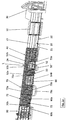
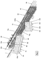
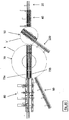
- the device 10 has a single-track first horizontal conveyor 20, which has a conveyor track 21.
- the conveyor track 21 of the first horizontal conveyor 20 may be formed in a known manner by a row of driven rollers 22. But it is also possible to use a circulating conveyor belt or similar device for this purpose.
- the first horizontal conveyor 20 has a support means 23 which, in the embodiment described here, is inclined, preferably inclined at 6 ° to the vertical, and on which the glass sheets are supported during their transport movement. Also, such a horizontal conveyor 20 is known and therefore need not be described in detail.
- a washing station 30 in which to be assembled to the insulating glass pane glass panels are cleaned.
- the glass panels set up in a receiving station (not shown) and cleaned in the washing station 30 are brought by the first horizontal conveyor 20 - past a visit and frame setting station 32 - to an outfeed device 40, the structure and function of which will be described below.
- a rotating station 50 is arranged, the two conveyor tracks 51 a and 51 b (see FIG.
- the rotating station 50 driven by a drive means 50 "has a length which allows glass panels 1A, 2A to be inserted therein, these glass panels 1A, 2A having a first length l 1.
- a rotating frame 52 of the rotating station 50 is substantially orthogonal Rotatable to the conveying direction of the glass panels axis, so that after a 180 ° rotation of the in FIG. 1 front end 52a, which faces a buffer station 70, in the rotated state then the first horizontal conveyor 20 and its second end 52b of the buffer station 70 faces.
- the rotary frame 52 rotatably driven by a drive device 50 ' is essentially formed by two support walls 53a and 53b inclined relative to the vertical, preferably at an angle of 6 °, having a plurality of support rollers (not shown) along which the glass sheets are movable ,
- the supported by the first support wall 53a glass plate sets with its lower edge in this case on rollers of the first conveyor track 51 a and on the second support wall 52b supporting glass plate sets on rollers of the second conveyor track 51 b.
- the rotary station 50 is thus formed in two lanes and the rollers of the first conveyor track 51 a and the rollers of the second conveyor track 51 b are independently drivable, so that - as described below - on each of the two tracks of the rotary station 50 one or more located on a track Glass panels can be moved independently of the located on the other track glass panels.
- the structure and operation of the rotary station 50 is on the DE 10 2012 000 464 A1 Reference is made, the disclosure of which is the subject of the present application by this reference.
- the second horizontal conveyor 60 has two preferably independently drivable sections 60a and 60b.
- the first portion 60a passes through the buffer station 70 and the second portion 60b passes through an assembly and press station 80.
- the construction of a preferred embodiment of the buffer station 70 and the assembly and press station 80 are in the international patent application WO 2005/080739 to which reference is made to avoid repetition and their disclosure by this reference to the subject this application is made. In the following, therefore, the special design, the buffer station 70 and the assembly and pressing station 80 will be explained only to the extent that is expedient or necessary for the understanding of this application.
- the buffer station 70 of the device 1 described here is designed to be rotatable, so that after a rotation of 180 ° in her FIG. 1 front end 70a, which is associated with the rotating station 50, in the rotated state then the assembly and pressing station 80 and its rear end 70b of the rotating station 50 faces.
- the driven by a drive device 70c buffer station 70 has a rotatably driven by the drive means 70c rotary frame 72, which - as well as the rotating frame 52 of the rotating station - against the vertical, preferably at an angle of 6 °, inclined support walls 73a and 73b having a Has a plurality of support rollers (not shown), along which the glass sheets are movable.
- the rotatable buffer station 70 in this case has a length which allows at least one glass panel 3A, which has a length l 2 with l 2 > l 1 to introduce and rotate.
- the supported by the first support wall 73a glass plate sets with its lower edge thereby on rollers of a first conveyor track 61a of the first portion 60a of the second horizontal conveyor 60 and on the second support wall 73b supporting glass plate sets on rollers of a second conveyor belt 61 b of the first portion 60a of second horizontal conveyor.
- the buffer station 70 is thus - like the turning station 50 - formed in two lanes and the rollers of the first conveyor track 61 a and the second conveyor track 61 b of the first portion 60 a and the second portion 60 b of the second horizontal conveyor 60 are preferably independently driven, so that for each of the two tracks of the buffer station 70 and / or the assembly and pressing station 80 can be moved one or more on one track glass panels independently of the located on the other track glass panels.
- a first glass panel pair 1AB composed of two glass sheets 1A and 1B is already present in the buffer station 70; a first glass sheet 2A is inserted in the turning station 50.
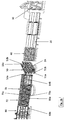
- the second pair of glass panel 2AB is then introduced into the buffer station 70, wherein during the introduction process of this second glass panel pair 2AB the already located in the buffer station 70 first glass panel pair 1AB is moved further, so that then the two Glass panel pair 1AB and 2AB are located in the buffer station 70.
- These are then introduced in a manner known per se and therefore not described in more detail from the second horizontal conveyor 60 in the assembly and pressing station 80 and assembled there in a likewise known manner to form a double insulating glass pane.
- the "large" glass sheets 3A, 3B are then paired to form a glass sheet pair 3AB, just as the "small” glass sheets 1A, 1B and 2A, 2B in the rotating station 50 are paired with glass sheet pairs 1AB and 2AB, respectively were.
- the glass panel pair 3AB is then introduced into this station in a manner known per se by the first section 60a of the second horizontal conveyor 60 and its second section 60b passing through the assembly and pressing station 80 and converted in a known manner into a double section. Insulated glass pane assembled.
- the rotatable buffer station 70 serves to glass panel pairs 1AB and 2AB, respectively, for buffering these glass panel pairs before they be introduced together into the assembly and pressing station 80.
- the buffer station 70 therefore preferably has a length which is dimensioned such that not only "large” glass sheets 3A, 3B having the length l 2 can be processed therein, but also at least two "small” glass sheets in it Pairs 1AB, 2AB, which have a length l 1 , can be accommodated.
- the buffer station 70 in such a way that more than two glass panel pairs 1AB, 2AB, each having the length h, can be accommodated in it.
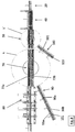
- the device 1 'of the second embodiment has a buffer station 70', which is now - in contrast to the rotatable buffer station 70 of the first embodiment - not necessarily rotatable, but is stationary in the embodiment described here.
- this buffer station 70 ' which is arranged between a turning station 50 of the first embodiment corresponding turning station 50' and the assembly and pressing station 80, although advantageous for an efficient production process, but not mandatory and therefore can also be omitted.
- the rotating station 50' takes over the function of the rotatable buffer station 70 of the first embodiment, that is, it is designed so that it both the smaller "Glass sheets 1A, 1B, 2A, 2B, which have the length l 1 , as well as those" large "glass sheets 3A, 3B having a length l 2 > l 1 allowed.
- the rotating station 50 ' has a rotating device 50a', which is formed like the rotating station 50 of the first embodiment and is therefore not described in detail.
- the turning station 50' of the second embodiment and the turning station 50 of the first embodiment has two connectable extension devices 50b 'and 50c', which is connected to the rotator 50a ' can be coupled and thus the rotating device 50a 'extend so far that with her also "large" glass panels 3A, 3B are rotatable.
- the extension devices 50b 'and 50c' are each arranged on one side of the rotary device 50a '.
- the solution is not preferred since this results in an asymmetrical structure of the rotating station 50 '.
- Each of the two extension devices 50b 'and 50c' preferably has in each case a frame 52 'with each inclined against the vertical support walls 53a' and 53b ', which are aligned with the support walls 53a, 53b of the rotating frame 52 of the rotator 50a'.
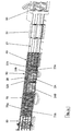
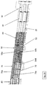
- the operation of the device 1 'of the second embodiment is now as follows: If' small 'glass panels are to be processed with the device 1', then the two extension devices 50b 'and 50c' are decoupled from the rotator 50a ', as shown in FIG. 3a is shown. In this first mode Thus, only the rotating device 50a 'of the rotating station 50' rotates in the device 1 '. This corresponds to the function of the rotating station 50 of the first embodiment. A first glass sheet 1A is - as described above - introduced through the first extension means 50b 'in the rotator 50a', this is then rotated by 180 °.
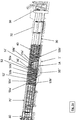
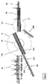
- FIG. 4a In order now in the turning station 50 'and "large" glass panels 3A, 3B to rotate, is now - as out FIG. 4a can be seen - provided that the extension devices 50b 'and 50c' are coupled to the rotator 50a ', so that these two extension devices 50b' and 50c 'together with the rotator 50a' can be rotated.
- a first glass sheet 3A is then inserted into the rotating station 50a thus extended (in the same way as the "small" glass sheets 1A and 2A are introduced into the turning station 50) ( FIG. 4b ).
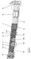
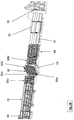
- the turning station 50 ' will then - as out Figure 4c visible - rotated by 180 °.
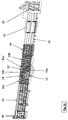
- the second glass sheet 3B is inserted into the rotating station 50 ', whereby the glass sheet pair 3AB is formed. This will then - as in FIG. 4d shown - introduced by the buffer station 70 'or directly into the assembly and pressing station 80.
- the devices 1 and 1 'described thus allow in an advantageous manner by the above-described two modes of operation a "tandem mode" in which a single production line both "small” glass sheets 1A-2B, that is, glass sheets of length l 1, in the turning station 50 and in the rotator 50 'can be introduced and rotated in this, as well as "large” Glass panels 3A, 3B, that is, glass panels of length l 2 > l 1 , which no longer fit into the rotating station 50 and in the rotator 50 'to process, without thereby in particular in the processing of these aforementioned "small” glass panels no opposite the one from the DE 10 2012 000 464 A1 or the WO 2013/104542 A1 known device, a reduced efficiency, in particular a higher cycle time occurs.
- the unloading station 40 Before the glass sheets 1A, 2B, 3A, 3B are transported by the first horizontal conveyor 20 from the washing station 30 to the rotary station 50, they pass through the unloading station 40. Their task is a glass panel located on the conveyor track 21 of the first horizontal conveyor 20 to remove from this track, so that by the first horizontal conveyor 20, the further glass panel placed behind this glass panel can be promoted from the washing station 30 to the rotating station 50.
- the removal station 40 thus displaces a glass panel in it from the first track formed by the conveyor belt 21 of the first horizontal conveyor 20 to a second track in which the glass panel thus displaced can be "parked".
- this removal station 40 is in turn to the aforementioned patent applications of DE 10 2012 000 464 A1 and the WO 2013/104542 A1 directed.
- the retrieval station 40 is in turn advantageous if the described devices 1, 1 'not only - as described above - double insulating glass panes, but in particular triple insulating glass panes to be produced.
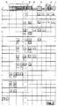
- third glass sheets 1C and 2C are moved through the rotating station 50 and the rotatable buffer station 70 on the first conveying track 61a of the second horizontal conveyor 60 to the assembling and pressing station 80, opposite to the glass sheet pairs 1AB, 2AB already located and assembled therein ( Line 9) and then assembled by a corresponding operation of the assembly and pressing station 80 into "small" triple insulating glass panes 1ABC, 2ABC (line 10).
- WO 2013/104542 A1 directed.
- the two "large” glass sheets 3A and 3B are paired as described above in the rotatable buffer station 70 of the apparatus 1 (lines 1 to 3 of FIG. 6 ).
- the two glass sheets 3A and 3B are then conveyed from the two conveying tracks 61a and 61b of the second horizontal conveyor 60 to the assembling and pressing station 80, assembled there into a glass sheet pair 3AB, and assembled on the second conveying track 61b side - And pressing station 80 filed.
- the device described is not only suitable for the efficient production of insulating glass panes of different lengths, but also advantageously makes it possible to simplify their manufacture, according to a method described in US Pat FIGS. 7 to 10 illustrated third embodiment, a input and / or rejection of individual glass panels is feasible.
- the third embodiment corresponds to its basic structure according to the first of the two embodiments described above, so that corresponding components provided with the same reference numerals and will not be described in detail.
- the rotatable buffer station 70 of the device an input and / or Ausschlatestation, hereinafter briefly lock station 90, is assigned.
- This lock station 90 serves to remove individual glass sheets 1A-3B from the transport path of the glass sheets, if this is required or required for manufacturing reasons. In particular, defective glass sheets 1A-3B or glass sheets, which for other reasons are to be removed from the transport path to the assembly and pressing station 80, can thereby be removed.
- the third embodiment of the described device 1 thus allows an individual discharge of a glass sheet 1A-3B located in the transport path, which will be described in detail below.
- the lock station 90 is arranged at the turning circle K of the rotatable buffer station 70 such that in a discharge position of the buffer station 70 located in this, NASAschleusende glass panel can be transferred from the buffer station 70 in the lock station 90.
- the buffer station 70 of hers in the FIGS. 7 and 8th shown basic position in which the buffer station 70 is in the transport path of the glass sheets 1A-3B - as described above - in an in FIG. 9 moved lock position shown.
- the rotatable buffer station 70 is oriented such that one or more glass sheets 1A-3B can be transferred to the lock station 90.
- the lock station 90 - as in FIG. 7 illustrated - a horizontal conveyor 91 with a conveyor track 91 ', which - according to the conveyor track 21 of the first horizontal conveyor 20 - is formed by a row of driven rollers 92.
- the lock station 90 has a support 93 which, in the case shown here, has a support wall 93a which has a plurality of support rollers (not shown) along which the glass sheets are movable. The supported by the support wall 93a glass panel sets with its lower edge on the rollers 92 of the conveyor track 91 'of the horizontal conveyor 91.
- the formation of the support wall 93a corresponds to that of the support wall 73a of the buffer station 70 and, like this, is inclined with respect to the vertical, so that in the lock position of the buffer station 70 the support wall 93a is aligned with the corresponding support wall 73a or 73b of the buffer station 70.
- the glass panel to be ejected can thus be easily moved from the corresponding support wall 73a or 73b to the support wall 93a of the lock station 90.
- the lock station 90 consists of two units 90a and 90b, which are formed as described above. This is not mandatory. Rather, it is also possible that the support wall 93a and the conveyor track 91 'are integrally formed.
- the support device 93 has a support wall 93a with support rollers. This is not mandatory. It is also possible to provide, instead of the support rollers, an air cushion or similar means which causes the glass panels 1A-3B to be supported as they move through the conveyor track 91 '.
- the glass sheet 3 A which is located on the first conveying path 61 a of the first portion 60 a of the second horizontal conveyor 60 and is supported by the first support wall 73 b of the rotary buffer station 70 are brought into the lock station 90, the rotatable buffer station 70 so far rotated until the first support wall 73a with the support wall 93a of the lock station 90 is aligned.
- the first conveyor track 61 a of the rotatable buffer station 70 and the conveyor track 91 'of the horizontal conveyor 91 of the lock station 90 then move this glass panel 3A from the rotatable buffer station 70 into the lock station 90, whereby it is discharged from the transport path of the device 1.
- the glass sheets 1A-3B are already paired with the rotatable buffer station 70, it is necessary or expedient to remove another glass sheet from the rotatable buffer station 70 and thus from the apparatus 1 for a variety of applications.
- a correlated with the glass sheet 3 A glass panel 3 B which is located on the second conveyor track 61 b of the first portion 60 a of the second horizontal conveyor 60 and is supported by the second support wall 73 b of the rotatable buffer station are discharged from the device 1, the rotatable buffer station 70 is rotated such that the second support wall 73b with the support wall 93a of the lock station 90 is aligned.
- the discharging of this second glass sheet 3 B is then the same as the previously described discharging the first glass sheet 3 A.
- the lock station 90 is formed in one lane, ie, that the horizontal conveyor 91 has only a single conveyor track 91 a. From the above-described discharge of the second glass sheet 3B, it is quite expedient that two or more glass sheets located on different conveyor tracks 61a and 61b are discharged simultaneously or in succession. For this purpose, it is expedient that the lock station 90 is formed two lanes. It then has - not shown in the figures - a further conveyor track and a further support means, which are formed according to the conveyor track 91a and the support means 93. The support walls 93a are thus again arranged in a V-shape.
- the lock station 90 has a length which corresponds to the length of the buffer station 70, so that "large” glass panels 3A, 3B can also be accommodated in the lock station 90.
- the lock station 90 has only one of the two units 90a and 90b forming it.
- the procedure is as follows: The glass sheet to be inserted is fed into the lock station 90. Then, the buffer station 70 is moved to its lock position, so that in turn the rotatable buffer station 70 and the lock station 90 are aligned. Then, from the conveyor track 91 'of the horizontal conveyor 91 of the lock station 90, the glass panel placed in it is introduced into the rotatable buffer station 70.
- the device 1 has a further lock station 100, which is assigned to the rotary station 50 and arranged at its turning circle K '. This then serves for the discharge of glass sheets 1A-2B from the turning station 50.
- the further lock station 100 has a horizontal conveyor 101, which has a conveyor track 101 'with rollers 102. It is a support means 103 provided with a support wall 103a, which also has not shown support rollers here.
- the support wall 103a of the support device 103 is in turn inclined to the vertical in such a way that it is aligned with the cooperating support wall 53a or 53b of the rotating station 50.
- the further lock station 100 is thus designed in accordance with the lock station 90, so that a further description of the same is not required.
- the input and / or ejection of a glass sheet from or into the rotating station 50 is carried out accordingly the manner in which the input and / or ejection of a glass sheet from the rotatable buffer station 70.
- Locking station 90 shown - is formed single track. But it is - as described above in the lock station 90 described above - possible to form the further lock station 100 two lanes, so that it then has two conveyor tracks and two support means, which are preferably oriented inclined opposite to the vertical, so that in turn the V-shaped Design is given. In the lock position of the lock station 90, one of the two support walls 53a or 53b then aligns with the support wall 103 and the second support wall 53b or 53a with the further support wall. The statements made on the two-lane design of the lock station 90 apply correspondingly to the further lock station 100.
- the described device can also be designed according to the second embodiment, i. h., That the turning station 50 'is enlarged, so as to process also large glass panel 3A, 3B, as described with reference to the second embodiment.
- the further lock station 100 preferably has a length which also allows the discharge of large glass sheets 3A, 3B. It then corresponds to its function and its structure after the lock station 90.
- the turning circle K 'of the rotating station 50' is then given by its length and the length of one or preferably both extension devices 50b 'and 50c'.
Landscapes
- Engineering & Computer Science (AREA)
- Civil Engineering (AREA)
- Structural Engineering (AREA)
- Joining Of Glass To Other Materials (AREA)
- Securing Of Glass Panes Or The Like (AREA)
- Automobile Manufacture Line, Endless Track Vehicle, Trailer (AREA)
Claims (15)
- Dispositif servant à assembler des vitrages isolants (1AB, 2AB ; 3AB) composés de plaques de verre (1A, 1B, 2A, 2B ; 3A, 3B), lequel dispositif possède un premier convoyeur horizontal (20) pourvu d'une voie de convoyage (21), une station de retournement (50), un deuxième convoyeur horizontal (60) pourvu de deux voies de convoyage (61a, 61b) et une station d'assemblage et de compression (80), dans lequel le premier convoyeur horizontal (20) convoie les plaques de verre (1A - 3B) à assembler en des vitrages isolants (1AB, 21AB ; 3AB) en direction de la station de retournement (50) et que le deuxième convoyeur horizontal (60) convoie lesdites plaques de verre de la station de retournement (50) en direction de la station d'assemblage et de compression (80), caractérisé en ce qu'une station de mise en tampon (70) rotative est disposée en aval de la station de retournement (50) dans la direction de convoyage des plaques de verre (1A - 2B ; 3A, 3B).
- Dispositif selon la revendication 1, caractérisé en ce que la station de mise en tampon (70) rotative présente un châssis de retournement (72) pourvu de parois de support (73a, 73b), qui s'étendent de manière inclinée par rapport à la verticale.
- Dispositif selon l'une quelconque des revendications précédentes, caractérisé en ce que la station de mise en tampon (70) rotative présente deux pistes de convoyage (61a, 61b), qui peuvent être entraînées de préférence indépendamment l'une de l'autre.
- Dispositif servant à assembler des vitrages isolants (1AB, 2AB ; 3AB) composés de plaques de verre (1A, 1B, 2A, 2B ; 3A, 3B), lequel possède un premier convoyeur horizontal (20) pourvu d'une voie de convoyage (21), une station de retournement (50'), un deuxième convoyeur horizontal (60) pourvu de deux pistes de convoyage (61a, 61b) et une station d'assemblage et de compression (80), dans lequel le premier convoyeur horizontal (20) convoie les plaques de verre (1A, 1B ; 2A, 2B ; 3A, 3B) à assembler en des vitrages isolants (1AB, 2AB ; 3AB) et que le deuxième convoyeur horizontal (60) convoie les plaques de verre (1A - 3B) de la station de retournement (50') en direction de la station d'assemblage et de compression (80), caractérisé en ce que la station de retournement (50') présente un système de retournement (50a') ainsi qu'au moins un système de rallonge (50b', 50c'), qui peut être couplé au système de retournement (50a') et qui peut être tourné par ce dernier dans l'état couplé.
- Dispositif selon la revendication 4, caractérisé en ce que la station de retournement (50') présente, au niveau de chaque côté du système de retournement (50a'), un système de rallonge (50b', 50c').
- Dispositif selon la revendication 4 ou 5, caractérisé en ce qu'au moins un système de rallonge (50b', 50c') présente un châssis de retournement (52') pourvu de parois de support (53a', 33b'), qui s'étendent de manière inclinés par rapport à la verticale.
- Dispositif selon l'une quelconque des revendications précédentes, caractérisé en ce que la station de retournement (50 ; 50') présente deux pistes de convoyage (51a, 51b), qui peuvent être entraînées indépendamment l'une de l'autre, et en ce que la première piste de convoyage (51a) et, dans l'état retourné de la station de retournement (50 ; 50'), la deuxième piste de convoyage (51b) sont alignées avec la première piste de convoyage (21) du premier convoyeur horizontal (20), et en ce que les pistes de convoyage (51a, 51b) de la station de retournement (50 ; 50') sont alignées avec les pistes de convoyage (61a, 61b) du premier tronçon (60a) du deuxième convoyeur horizontal (60) dans la position de base de la station de retournement (50 ; 50') ainsi que dans sa position retournée.
- Dispositif selon l'une quelconque des revendications précédentes, caractérisé en ce que la station de retournement (50 ; 50') présente un châssis de retournement (52) pourvu de parois de support (53a, 53b), qui s'étendent de marnière inclinée par rapport à la verticale.
- Dispositif selon la revendication 1 ou la revendication 4, caractérisé en ce qu'une station de transfert (40) est disposée en amont ou en aval de la station de retournement (50 ; 50'), par laquelle l'une des plaques de verre avancée par le premier convoyeur horizontal (20) à une voie peut être déplacée hors du trajet de transport et peut être amenée sur une voie de mise en attente permettant un passage d'une plaque de verre qui suit.
- Dispositif selon l'une quelconque des revendications précédentes, caractérisé en ce que le premier tronçon (60a) et le deuxième tronçon (60b) du deuxième convoyeur horizontal (60) peuvent être entraînés indépendamment l'un de l'autre.
- Dispositif selon l'une quelconque des revendications précédentes, caractérisé en ce que le dispositif (1) présente une station à sas (90), qui est associée à la station de mise en tampon (70) rotative.
- Dispositif selon l'une quelconque des revendications précédentes, caractérisé en ce que le dispositif (1) présente une autre station à sas (100), qui est associée à la station de retournement (50).
- Procédé servant à assembler des vitrages isolants (1AB, 2AB ; 3AB) composés de plaques de verre (1A, 1B, 2A, 2B ; 3A, 3B), dans le cadre auquel les plaques de verre (1A, 1B, 2A, 2B) sont convoyées en direction d'une station de retournement (50) par un premier convoyeur horizontal (20) à une voie, en ce qu'une première plaque de verre (1A ; 2A) de deux plaques de verre (1A, 1B ; 2A, 2B) réalisant une paire de plaques de verre (1AB, 2AB) est tournée de 180° et est appariée à une deuxième plaque de verre (1B ; 2B), et en ce que la paire ainsi formée de plaques de verre (1AB, 2AB) est convoyée par un deuxième convoyeur horizontal (60) en direction d'une station d'assemblage et de compression (80), caractérisé en ce qu'aux fins de l'assemblage de plaques de verre (3A, 3B) supplémentaires, lesdites plaques de verre (3A, 3B) sont convoyées en passant par la station de retournement (50) en direction d'une station de mise en tampon (70) rotative, en ce que dans la station de mise en tampon (70) rotative, une première plaque de verre (3A) de deux plaques de verre (3A, 3B) réalisant une paire de plaques de verre (3AB) est tournée de 180° et est appariée, par la suinte, à la deuxième plaque de verre (3B) introduite dans la station de mise en tampon (70) rotative.
- Procédé selon la revendication 13, caractérisé en ce que les plaques de verre (1A, 1B, 2A, 2B ; 3A, 3B) appariées dans la station de mise en tampon (70) rotative sont introduites par le deuxième convoyeur horizontal (60) dans la station d'assemblage et de compression (80).
- Procédé selon la revendication 14, caractérisé en ce que la paire de plaques de verre (1AB, 2AB ; 3AB) formée à partir des plaques de verre (1A, 1B, 2A, 2B ; 3A, 3B) est déposée sur un côté de la station d'assemblage et de coznpzession (80), en ce qu'une autre plaque de verre (1C, 2C ; 3C) est introduite dans la station d'assemblage et de compression (80) et est assemblée à la paire de plaques de verre (1AB, 2AB ; 3AB) s'y trouvant déjà afin de former un triple vitrage isolant (1ABC, 2ABC ; 3ABC).
Applications Claiming Priority (3)
| Application Number | Priority Date | Filing Date | Title |
|---|---|---|---|
| DE202013011411.8U DE202013011411U1 (de) | 2013-12-20 | 2013-12-20 | Vorrichtung zum Zusammenbau von Isolierglasscheiben |
| DE102013021731.8A DE102013021731B4 (de) | 2013-12-20 | 2013-12-20 | Vorrichtung und Verfahren zum Zusammenbau von Isolierglasscheiben |
| PCT/EP2014/003451 WO2015090613A1 (fr) | 2013-12-20 | 2014-12-20 | Dispositif et procédé permettant l'assemblage de vitres isolantes |
Publications (2)
| Publication Number | Publication Date |
|---|---|
| EP2964863A1 EP2964863A1 (fr) | 2016-01-13 |
| EP2964863B1 true EP2964863B1 (fr) | 2016-08-24 |
Family
ID=52358736
Family Applications (1)
| Application Number | Title | Priority Date | Filing Date |
|---|---|---|---|
| EP14828015.9A Not-in-force EP2964863B1 (fr) | 2013-12-20 | 2014-12-20 | Dispositif et procédé permettant l'assemblage de vitres isolantes |
Country Status (4)
| Country | Link |
|---|---|
| US (1) | US20160290034A1 (fr) |
| EP (1) | EP2964863B1 (fr) |
| CA (1) | CA2934337A1 (fr) |
| WO (1) | WO2015090613A1 (fr) |
Cited By (2)
| Publication number | Priority date | Publication date | Assignee | Title |
|---|---|---|---|---|
| US10689208B2 (en) | 2016-07-12 | 2020-06-23 | Lisec Austria Gmbh | Conveying apparatus |
| WO2025052204A1 (fr) * | 2023-09-04 | 2025-03-13 | Forel S.P.A. Unipersonale | Procede de fabrication d'un verre isolant |
Families Citing this family (4)
| Publication number | Priority date | Publication date | Assignee | Title |
|---|---|---|---|---|
| IT201700071422A1 (it) * | 2017-06-27 | 2018-12-27 | Forel Spa | Impianto automatico e procedimento automatico per la fabbricazione ad elevata produttivita’ del vetro isolante costituito da almeno due lastre di vetro ed almeno un telaio distanziatore |
| DE102019123696A1 (de) * | 2019-09-04 | 2021-03-04 | Bystronic Lenhardt Gmbh | Verfahren und Vorrichtung zum Zusammenbauen von Isolierglasscheiben sowie dadurch hergestellte Isolierglasscheibe |
| DE102019123700A1 (de) * | 2019-09-04 | 2021-03-04 | Bystronic Lenhardt Gmbh | Verfahren und Vorrichtung zum Zusammenbauen von Isolierglasscheiben sowie dadurch hergestellte Isolierglasscheibe |
| DE102023126130B3 (de) | 2023-09-26 | 2024-09-05 | Glaston Germany GmbH | Verfahren und Vorrichtung zum Zusammenbauen einer zwei Außengläser und ein dazwischen liegendes Dünnglas enthaltenden Dreifach-Isolierglasscheibe |
Family Cites Families (3)
| Publication number | Priority date | Publication date | Assignee | Title |
|---|---|---|---|---|
| DE4437998C2 (de) * | 1994-02-01 | 1999-07-22 | Lenhardt Maschinenbau | Vorrichtung zum Zusammenbauen von Isolierglasscheiben |
| US8381382B2 (en) * | 2009-12-31 | 2013-02-26 | Cardinal Ig Company | Methods and equipment for assembling triple-pane insulating glass units |
| CA2860896A1 (fr) * | 2012-01-13 | 2013-07-18 | Plus Inventia Ag | Dispositif et procede d'assemblage de vitrages isolants |
-
2014
- 2014-12-20 WO PCT/EP2014/003451 patent/WO2015090613A1/fr not_active Ceased
- 2014-12-20 CA CA2934337A patent/CA2934337A1/fr not_active Abandoned
- 2014-12-20 EP EP14828015.9A patent/EP2964863B1/fr not_active Not-in-force
-
2016
- 2016-06-17 US US15/186,312 patent/US20160290034A1/en not_active Abandoned
Cited By (2)
| Publication number | Priority date | Publication date | Assignee | Title |
|---|---|---|---|---|
| US10689208B2 (en) | 2016-07-12 | 2020-06-23 | Lisec Austria Gmbh | Conveying apparatus |
| WO2025052204A1 (fr) * | 2023-09-04 | 2025-03-13 | Forel S.P.A. Unipersonale | Procede de fabrication d'un verre isolant |
Also Published As
| Publication number | Publication date |
|---|---|
| US20160290034A1 (en) | 2016-10-06 |
| CA2934337A1 (fr) | 2015-06-25 |
| EP2964863A1 (fr) | 2016-01-13 |
| WO2015090613A1 (fr) | 2015-06-25 |
Similar Documents
| Publication | Publication Date | Title |
|---|---|---|
| EP2964863B1 (fr) | Dispositif et procédé permettant l'assemblage de vitres isolantes | |
| EP2802727B1 (fr) | Dispositif et procédé d'assemblage de vitrages isolants | |
| DE102015002887A1 (de) | Richtmaschine und Verfahren zum Wechseln von Richtrollenelementen | |
| EP2613996B1 (fr) | Dispositif de transport de carrosseries | |
| DE102012000464B4 (de) | Vorrichtung und Verfahren zum Zusammenbau von Isolierglasscheiben | |
| EP3133234B1 (fr) | Procede et dispositif d'assemblage de panneaux en verre et de vitres isolantes | |
| DE4437998C2 (de) | Vorrichtung zum Zusammenbauen von Isolierglasscheiben | |
| DE102019123700A1 (de) | Verfahren und Vorrichtung zum Zusammenbauen von Isolierglasscheiben sowie dadurch hergestellte Isolierglasscheibe | |
| EP3328765B1 (fr) | Dispositif de transport | |
| DE102013021731B4 (de) | Vorrichtung und Verfahren zum Zusammenbau von Isolierglasscheiben | |
| DE2146554C3 (de) | Verfahren und Vorrichtung zum LangroUen und/oder Langwirken von Teigstucken Fr. Winkler KG, Spezialfabrik für Bäckereimaschinen und Backöfen, 7730 Villingen | |
| DE202013011411U1 (de) | Vorrichtung zum Zusammenbau von Isolierglasscheiben | |
| EP1398141A2 (fr) | Machine a plier | |
| DE102011103289B4 (de) | Arbeitsverfahren und Vorrichtung zum Zusammenlegen von Komponenten von Sandwich-Rahmentüren und Sandwich-Rahmen-Möbelbauplatten | |
| EP1877233A2 (fr) | Dispositif pour separer un boudin d'argile plastique au moyen d'un dispositif d'entaille agissant sur tous les cotes | |
| DE102019123696A1 (de) | Verfahren und Vorrichtung zum Zusammenbauen von Isolierglasscheiben sowie dadurch hergestellte Isolierglasscheibe | |
| DE2305620C2 (de) | Vorrichtung und Verfahren zum Herstellen bogenförmiger Bauplatten | |
| DE202012000280U1 (de) | Vorrichtung zum Zusammenbau von Isolierglasscheiben | |
| DE102011122687A1 (de) | Verfahren und Einrichtung zum Bestücken eines mehrlagigen Vollholz-Verbundbauteiles mit einer jeweils geradzahligen Bretter-Lage | |
| DE2109098C3 (de) | Vorrichtung zum Stapeln einer Reihe von Scheiben im wesentlichen senkrecht auf einer Stapelfläche | |
| EP3449079B1 (fr) | Procédé et dispositif de scellement d'ébauches de vitrage isolant | |
| DE2520625A1 (de) | Verfahren und vorrichtung zur herstellung einer umverpackung fuer gegenstaende aus einer mit diesen gegenstaenden beladenen falthuelle | |
| DE2352832A1 (de) | Verfahren und anlage zum herstellen von doppelscheibenisolierglas | |
| DE102015002184A1 (de) | Transporteinheit, Rollenverbund und Sortiereinrichtung sowie Verfahren zum Anbringen einer Transporteinheit in einer Sortiervorrichtung | |
| CH695553A5 (de) | Vorrichtung zum Aufrichten von Behältern. |
Legal Events
| Date | Code | Title | Description |
|---|---|---|---|
| PUAI | Public reference made under article 153(3) epc to a published international application that has entered the european phase |
Free format text: ORIGINAL CODE: 0009012 |
|
| 17P | Request for examination filed |
Effective date: 20151006 |
|
| AK | Designated contracting states |
Kind code of ref document: A1 Designated state(s): AL AT BE BG CH CY CZ DE DK EE ES FI FR GB GR HR HU IE IS IT LI LT LU LV MC MK MT NL NO PL PT RO RS SE SI SK SM TR |
|
| AX | Request for extension of the european patent |
Extension state: BA ME |
|
| GRAP | Despatch of communication of intention to grant a patent |
Free format text: ORIGINAL CODE: EPIDOSNIGR1 |
|
| INTG | Intention to grant announced |
Effective date: 20160408 |
|
| GRAS | Grant fee paid |
Free format text: ORIGINAL CODE: EPIDOSNIGR3 |
|
| GRAA | (expected) grant |
Free format text: ORIGINAL CODE: 0009210 |
|
| DAX | Request for extension of the european patent (deleted) | ||
| AK | Designated contracting states |
Kind code of ref document: B1 Designated state(s): AL AT BE BG CH CY CZ DE DK EE ES FI FR GB GR HR HU IE IS IT LI LT LU LV MC MK MT NL NO PL PT RO RS SE SI SK SM TR |
|
| REG | Reference to a national code |
Ref country code: GB Ref legal event code: FG4D Free format text: NOT ENGLISH |
|
| REG | Reference to a national code |
Ref country code: CH Ref legal event code: EP |
|
| REG | Reference to a national code |
Ref country code: AT Ref legal event code: REF Ref document number: 823283 Country of ref document: AT Kind code of ref document: T Effective date: 20160915 |
|
| REG | Reference to a national code |
Ref country code: IE Ref legal event code: FG4D Free format text: LANGUAGE OF EP DOCUMENT: GERMAN |
|
| REG | Reference to a national code |
Ref country code: DE Ref legal event code: R096 Ref document number: 502014001324 Country of ref document: DE |
|
| REG | Reference to a national code |
Ref country code: LT Ref legal event code: MG4D |
|
| REG | Reference to a national code |
Ref country code: NL Ref legal event code: MP Effective date: 20160824 |
|
| PG25 | Lapsed in a contracting state [announced via postgrant information from national office to epo] |
Ref country code: FI Free format text: LAPSE BECAUSE OF FAILURE TO SUBMIT A TRANSLATION OF THE DESCRIPTION OR TO PAY THE FEE WITHIN THE PRESCRIBED TIME-LIMIT Effective date: 20160824 Ref country code: LT Free format text: LAPSE BECAUSE OF FAILURE TO SUBMIT A TRANSLATION OF THE DESCRIPTION OR TO PAY THE FEE WITHIN THE PRESCRIBED TIME-LIMIT Effective date: 20160824 Ref country code: NO Free format text: LAPSE BECAUSE OF FAILURE TO SUBMIT A TRANSLATION OF THE DESCRIPTION OR TO PAY THE FEE WITHIN THE PRESCRIBED TIME-LIMIT Effective date: 20161124 Ref country code: HR Free format text: LAPSE BECAUSE OF FAILURE TO SUBMIT A TRANSLATION OF THE DESCRIPTION OR TO PAY THE FEE WITHIN THE PRESCRIBED TIME-LIMIT Effective date: 20160824 Ref country code: NL Free format text: LAPSE BECAUSE OF FAILURE TO SUBMIT A TRANSLATION OF THE DESCRIPTION OR TO PAY THE FEE WITHIN THE PRESCRIBED TIME-LIMIT Effective date: 20160824 Ref country code: RS Free format text: LAPSE BECAUSE OF FAILURE TO SUBMIT A TRANSLATION OF THE DESCRIPTION OR TO PAY THE FEE WITHIN THE PRESCRIBED TIME-LIMIT Effective date: 20160824 Ref country code: IT Free format text: LAPSE BECAUSE OF FAILURE TO SUBMIT A TRANSLATION OF THE DESCRIPTION OR TO PAY THE FEE WITHIN THE PRESCRIBED TIME-LIMIT Effective date: 20160824 |
|
| PG25 | Lapsed in a contracting state [announced via postgrant information from national office to epo] |
Ref country code: ES Free format text: LAPSE BECAUSE OF FAILURE TO SUBMIT A TRANSLATION OF THE DESCRIPTION OR TO PAY THE FEE WITHIN THE PRESCRIBED TIME-LIMIT Effective date: 20160824 Ref country code: GR Free format text: LAPSE BECAUSE OF FAILURE TO SUBMIT A TRANSLATION OF THE DESCRIPTION OR TO PAY THE FEE WITHIN THE PRESCRIBED TIME-LIMIT Effective date: 20161125 Ref country code: SE Free format text: LAPSE BECAUSE OF FAILURE TO SUBMIT A TRANSLATION OF THE DESCRIPTION OR TO PAY THE FEE WITHIN THE PRESCRIBED TIME-LIMIT Effective date: 20160824 Ref country code: LV Free format text: LAPSE BECAUSE OF FAILURE TO SUBMIT A TRANSLATION OF THE DESCRIPTION OR TO PAY THE FEE WITHIN THE PRESCRIBED TIME-LIMIT Effective date: 20160824 Ref country code: PT Free format text: LAPSE BECAUSE OF FAILURE TO SUBMIT A TRANSLATION OF THE DESCRIPTION OR TO PAY THE FEE WITHIN THE PRESCRIBED TIME-LIMIT Effective date: 20161226 |
|
| PG25 | Lapsed in a contracting state [announced via postgrant information from national office to epo] |
Ref country code: EE Free format text: LAPSE BECAUSE OF FAILURE TO SUBMIT A TRANSLATION OF THE DESCRIPTION OR TO PAY THE FEE WITHIN THE PRESCRIBED TIME-LIMIT Effective date: 20160824 Ref country code: RO Free format text: LAPSE BECAUSE OF FAILURE TO SUBMIT A TRANSLATION OF THE DESCRIPTION OR TO PAY THE FEE WITHIN THE PRESCRIBED TIME-LIMIT Effective date: 20160824 |
|
| REG | Reference to a national code |
Ref country code: DE Ref legal event code: R097 Ref document number: 502014001324 Country of ref document: DE |
|
| PG25 | Lapsed in a contracting state [announced via postgrant information from national office to epo] |
Ref country code: BE Free format text: LAPSE BECAUSE OF NON-PAYMENT OF DUE FEES Effective date: 20161231 Ref country code: PL Free format text: LAPSE BECAUSE OF FAILURE TO SUBMIT A TRANSLATION OF THE DESCRIPTION OR TO PAY THE FEE WITHIN THE PRESCRIBED TIME-LIMIT Effective date: 20160824 Ref country code: SM Free format text: LAPSE BECAUSE OF FAILURE TO SUBMIT A TRANSLATION OF THE DESCRIPTION OR TO PAY THE FEE WITHIN THE PRESCRIBED TIME-LIMIT Effective date: 20160824 Ref country code: CZ Free format text: LAPSE BECAUSE OF FAILURE TO SUBMIT A TRANSLATION OF THE DESCRIPTION OR TO PAY THE FEE WITHIN THE PRESCRIBED TIME-LIMIT Effective date: 20160824 Ref country code: SK Free format text: LAPSE BECAUSE OF FAILURE TO SUBMIT A TRANSLATION OF THE DESCRIPTION OR TO PAY THE FEE WITHIN THE PRESCRIBED TIME-LIMIT Effective date: 20160824 Ref country code: DK Free format text: LAPSE BECAUSE OF FAILURE TO SUBMIT A TRANSLATION OF THE DESCRIPTION OR TO PAY THE FEE WITHIN THE PRESCRIBED TIME-LIMIT Effective date: 20160824 Ref country code: BG Free format text: LAPSE BECAUSE OF FAILURE TO SUBMIT A TRANSLATION OF THE DESCRIPTION OR TO PAY THE FEE WITHIN THE PRESCRIBED TIME-LIMIT Effective date: 20161124 |
|
| PLBE | No opposition filed within time limit |
Free format text: ORIGINAL CODE: 0009261 |
|
| STAA | Information on the status of an ep patent application or granted ep patent |
Free format text: STATUS: NO OPPOSITION FILED WITHIN TIME LIMIT |
|
| 26N | No opposition filed |
Effective date: 20170526 |
|
| PG25 | Lapsed in a contracting state [announced via postgrant information from national office to epo] |
Ref country code: SI Free format text: LAPSE BECAUSE OF FAILURE TO SUBMIT A TRANSLATION OF THE DESCRIPTION OR TO PAY THE FEE WITHIN THE PRESCRIBED TIME-LIMIT Effective date: 20160824 |
|
| PG25 | Lapsed in a contracting state [announced via postgrant information from national office to epo] |
Ref country code: MC Free format text: LAPSE BECAUSE OF FAILURE TO SUBMIT A TRANSLATION OF THE DESCRIPTION OR TO PAY THE FEE WITHIN THE PRESCRIBED TIME-LIMIT Effective date: 20160824 |
|
| REG | Reference to a national code |
Ref country code: FR Ref legal event code: ST Effective date: 20170831 |
|
| REG | Reference to a national code |
Ref country code: IE Ref legal event code: MM4A |
|
| PG25 | Lapsed in a contracting state [announced via postgrant information from national office to epo] |
Ref country code: FR Free format text: LAPSE BECAUSE OF NON-PAYMENT OF DUE FEES Effective date: 20170102 Ref country code: LU Free format text: LAPSE BECAUSE OF NON-PAYMENT OF DUE FEES Effective date: 20161220 |
|
| PG25 | Lapsed in a contracting state [announced via postgrant information from national office to epo] |
Ref country code: IE Free format text: LAPSE BECAUSE OF NON-PAYMENT OF DUE FEES Effective date: 20161220 |
|
| REG | Reference to a national code |
Ref country code: BE Ref legal event code: MM Effective date: 20161231 |
|
| PG25 | Lapsed in a contracting state [announced via postgrant information from national office to epo] |
Ref country code: HU Free format text: LAPSE BECAUSE OF FAILURE TO SUBMIT A TRANSLATION OF THE DESCRIPTION OR TO PAY THE FEE WITHIN THE PRESCRIBED TIME-LIMIT; INVALID AB INITIO Effective date: 20141220 |
|
| PG25 | Lapsed in a contracting state [announced via postgrant information from national office to epo] |
Ref country code: MK Free format text: LAPSE BECAUSE OF FAILURE TO SUBMIT A TRANSLATION OF THE DESCRIPTION OR TO PAY THE FEE WITHIN THE PRESCRIBED TIME-LIMIT Effective date: 20160824 Ref country code: CY Free format text: LAPSE BECAUSE OF FAILURE TO SUBMIT A TRANSLATION OF THE DESCRIPTION OR TO PAY THE FEE WITHIN THE PRESCRIBED TIME-LIMIT Effective date: 20160824 Ref country code: IS Free format text: LAPSE BECAUSE OF FAILURE TO SUBMIT A TRANSLATION OF THE DESCRIPTION OR TO PAY THE FEE WITHIN THE PRESCRIBED TIME-LIMIT Effective date: 20160824 |
|
| REG | Reference to a national code |
Ref country code: CH Ref legal event code: PL |
|
| PG25 | Lapsed in a contracting state [announced via postgrant information from national office to epo] |
Ref country code: MT Free format text: LAPSE BECAUSE OF FAILURE TO SUBMIT A TRANSLATION OF THE DESCRIPTION OR TO PAY THE FEE WITHIN THE PRESCRIBED TIME-LIMIT Effective date: 20160824 |
|
| PG25 | Lapsed in a contracting state [announced via postgrant information from national office to epo] |
Ref country code: TR Free format text: LAPSE BECAUSE OF FAILURE TO SUBMIT A TRANSLATION OF THE DESCRIPTION OR TO PAY THE FEE WITHIN THE PRESCRIBED TIME-LIMIT Effective date: 20160824 Ref country code: AL Free format text: LAPSE BECAUSE OF FAILURE TO SUBMIT A TRANSLATION OF THE DESCRIPTION OR TO PAY THE FEE WITHIN THE PRESCRIBED TIME-LIMIT Effective date: 20160824 |
|
| PG25 | Lapsed in a contracting state [announced via postgrant information from national office to epo] |
Ref country code: CH Free format text: LAPSE BECAUSE OF NON-PAYMENT OF DUE FEES Effective date: 20171231 Ref country code: LI Free format text: LAPSE BECAUSE OF NON-PAYMENT OF DUE FEES Effective date: 20171231 |
|
| PGFP | Annual fee paid to national office [announced via postgrant information from national office to epo] |
Ref country code: DE Payment date: 20190226 Year of fee payment: 5 |
|
| GBPC | Gb: european patent ceased through non-payment of renewal fee |
Effective date: 20181220 |
|
| PG25 | Lapsed in a contracting state [announced via postgrant information from national office to epo] |
Ref country code: GB Free format text: LAPSE BECAUSE OF NON-PAYMENT OF DUE FEES Effective date: 20181220 |
|
| REG | Reference to a national code |
Ref country code: DE Ref legal event code: R119 Ref document number: 502014001324 Country of ref document: DE |
|
| PG25 | Lapsed in a contracting state [announced via postgrant information from national office to epo] |
Ref country code: DE Free format text: LAPSE BECAUSE OF NON-PAYMENT OF DUE FEES Effective date: 20200701 |
|
| REG | Reference to a national code |
Ref country code: AT Ref legal event code: MM01 Ref document number: 823283 Country of ref document: AT Kind code of ref document: T Effective date: 20191220 |
|
| PG25 | Lapsed in a contracting state [announced via postgrant information from national office to epo] |
Ref country code: AT Free format text: LAPSE BECAUSE OF NON-PAYMENT OF DUE FEES Effective date: 20191220 |