EP2964879B1 - Elektrische penetratorbaugruppe - Google Patents
Elektrische penetratorbaugruppe Download PDFInfo
- Publication number
- EP2964879B1 EP2964879B1 EP14760757.6A EP14760757A EP2964879B1 EP 2964879 B1 EP2964879 B1 EP 2964879B1 EP 14760757 A EP14760757 A EP 14760757A EP 2964879 B1 EP2964879 B1 EP 2964879B1
- Authority
- EP
- European Patent Office
- Prior art keywords
- conductor
- penetrator
- housing
- insulating housing
- bore
- Prior art date
- Legal status (The legal status is an assumption and is not a legal conclusion. Google has not performed a legal analysis and makes no representation as to the accuracy of the status listed.)
- Active
Links
Images







Classifications
-
- E—FIXED CONSTRUCTIONS
- E21—EARTH OR ROCK DRILLING; MINING
- E21B—EARTH OR ROCK DRILLING; OBTAINING OIL, GAS, WATER, SOLUBLE OR MELTABLE MATERIALS OR A SLURRY OF MINERALS FROM WELLS
- E21B33/00—Sealing or packing boreholes or wells
- E21B33/02—Surface sealing or packing
- E21B33/03—Well heads; Setting-up thereof
- E21B33/035—Well heads; Setting-up thereof specially adapted for underwater installations
- E21B33/038—Connectors used on well heads, e.g. for connecting blow-out preventer and riser
- E21B33/0385—Connectors used on well heads, e.g. for connecting blow-out preventer and riser electrical connectors
-
- H—ELECTRICITY
- H01—ELECTRIC ELEMENTS
- H01R—ELECTRICALLY-CONDUCTIVE CONNECTIONS; STRUCTURAL ASSOCIATIONS OF A PLURALITY OF MUTUALLY-INSULATED ELECTRICAL CONNECTING ELEMENTS; COUPLING DEVICES; CURRENT COLLECTORS
- H01R13/00—Details of coupling devices of the kinds covered by groups H01R12/70 or H01R24/00 - H01R33/00
- H01R13/46—Bases; Cases
- H01R13/52—Dustproof, splashproof, drip-proof, waterproof, or flameproof cases
- H01R13/523—Dustproof, splashproof, drip-proof, waterproof, or flameproof cases for use under water
-
- H—ELECTRICITY
- H02—GENERATION; CONVERSION OR DISTRIBUTION OF ELECTRIC POWER
- H02G—INSTALLATION OF ELECTRIC CABLES OR LINES, OR OF COMBINED OPTICAL AND ELECTRIC CABLES OR LINES
- H02G3/00—Installations of electric cables or lines or protective tubing therefor in or on buildings, equivalent structures or vehicles
- H02G3/22—Installations of cables or lines through walls, floors or ceilings, e.g. into buildings
Definitions
- the present invention relates generally to electrical penetrator assemblies for feed through of electrical power through the wall of a pressurized vessel or the like, and is particularly concerned with an electrical penetrator assembly for subsea use.
- Electrical penetrators are used to power subsea electric submersible pump (ESP) equipment and the like which pump hydrocarbons in oil well installations, and also in other applications such as high pressure downhole electrical penetrations and other penetrations to provide power to various types of subsea equipment.
- the penetrator extends through the wall or bulkhead of the vessel in which the equipment is located, and is normally connected to power cables at one end for connecting the equipment to an external power source.
- the connection or penetrator cannot be isolated from the pumping pressure for practical reasons. This creates an extreme environment for the connector or penetrator in terms of pressure, temperature, and high voltage.
- the penetrator must transfer power to the motor as well as maintaining a pressure barrier for both internal pressure created by the ESP and external pressure caused by the depth in seawater.
- the temperatures are increased due to fluid temperatures as well as resistive heating of the electrical elements.
- a one-piece conductor such as a conductive connector pin extends through a bore in an insulating sleeve or body, with appropriate seals brazed or bonded between the outer body and pin at each end of the penetrator assembly.
- the seals comprise metal sealing sleeves which seal the insulating sleeve of ceramic or the like to the conductive connector pin body. Due to the heat involved during the brazing or bonding process, the parts expand by different amounts.
- the different rates of shrinkage of the different material parts causes stress on the ceramic housing material, brittle bonds, or both, and may lead to failure of the seal. Additionally, most existing penetrators are designed for high pressure on one side only, and application of pressure on the other side may cause additional stress on the seal arrangement and the ceramic housing.
- US Patent No. 8,287,295 relates to an electrical penetrator assembly which has a ceramic housing with a through bore, a first electrical conductor extending through a first end of the bore and terminating short of a second end of the bore and having an outer end engageable with a first cable, and a second electrical conductor extending through a second end of the bore and terminating short of the first end of the bore, the second conductor having an outer end engageable with a second cable.
- the conductors are in electrical communication at their inner ends and at least one of the conductors is movable relative to the other conductor to accommodate expansion and contraction as a result of temperature variations, and first and second seals extend between respective ends of the ceramic housing and the first and second conductor, respectively.
- Embodiments described herein provide for an electrical penetrator assembly which is particularly suitable for high pressure, high temperature, and high voltage applications such as subsea use.
- an electrical penetrator assembly which comprises a ceramic housing having a through bore, a first electrical conductor extending through a first end of the bore and terminating short of a second end of the bore and having an outer end engageable with a first cable, a second electrical conductor extending through a second end of the bore and terminating short of the first end of the bore, the second conductor having an outer end engageable with a second cable, the conductors having slidably or telescopically engaging inner ends.
- First and second seals extend between the ceramic housing and first and second conductor, respectively, at each end of the assembly.
- a conductive layer or coating is provided on the inner diameter of the ceramic housing, between the housing and telescopically engaged conductors.
- the inner end of one conductor has a bore and the inner end of the other conductor is slidably engaged in the bore.
- An internal sliding contact band may be provided between the opposing faces of the bore and conductor inner end, to maintain electrical contact between the conductors as they move inwardly and outwardly.
- an electrical penetrator assembly comprises a ceramic housing having a through bore with opposite first and second ends, a rigid conductor extending into the first end of the bore and terminating short of the second end, and a flexible conductor secured to the inner end of the conductor and extending out of the second end of the bore, with a suitable seal arrangement between the conductor and bore at one end, and between the flexible conductor and bore at the other end of the assembly.
- the flexible conductor moves to compensate for different rates of thermal expansion and contraction of the rigid conductor, ceramic housing, and seals, reducing stress between the sealing sleeves and ceramic or insulating housing.
- a single conductor extends through the ceramic housing through bore and engages a conductive end member or socket member at the second end of the ceramic housing, with a pin and socket engagement between the single conductor and socket member or other interface arrangements allowing for axial contraction or expansion as a result of different coefficients of thermal expansion of the parts of the penetrator assembly.
- Certain embodiments as disclosed herein provide for an electrical penetrator assembly suitable for use in high pressure applications, such as in providing power for subsea equipment.
- FIGS. 1 to 4 illustrate a first embodiment of an electrical penetrator pin assembly or subassembly 10, while FIG. 6 illustrates the assembly 10 mounted in an outer penetrator housing 12 for extending through a wall or bulkhead of a subsea vessel or container.
- the pin subassembly 10 includes an outer body or housing 14 of ceramic or other dielectric material, the housing 14 having a through bore 15.
- First and second conductor members or pins 16, 18 having slidably engaged inner ends extend through the housing, with the first pin 16 extending through a first end 20 of the housing bore 15 and terminating short of the second end 22 of the bore, and the second pin 18 extending through the second end 22 of the bore and terminating short of the first end 20.
- the pins or conductor members are of suitable rigid conductive material such as copper or the like.
- the inner ends of the two pins are telescopically engaged, as illustrated in more detail in FIG. 2 , with the inner end of the first pin 16 having an inwardly extending bore 24 and inner end of the second pin 18 slidably or telescopically engaged in the bore, so that the overall length of the conductive pin assembly can vary.
- An internal sliding contact band 25 mounted in an annular recess in bore 24 provides a sliding electrical engagement or contact interface between the pins 16 and 18 while permitting the pins to telescope inwardly and outwardly to compensate for various types of stress, as discussed in more detail below.
- Band 25 provides a clearance between the opposing inner surface of bore 24 and outer surface of pin 18, while still providing electrical contact between the two pins or conductor halves at all times.
- the contact band may alternatively be mounted on the outer surface of the portion of pin 18 which engages in bore 24 in other embodiments.
- a cable connector 26 is provided at the outer end of the first pin for connection to a first cable on one side of the penetrator assembly, while cable connector 28 at the outer end of the second pin 18 is designed for connection to a second cable on the opposite side of the penetrator assembly.
- One of the cable connectors 28 is formed integrally with the pin, while the other cable connector 26 is formed separately and has a reduced diameter post 29 which is in threaded engagement in a bore 31 at the outer end of pin 16.
- Either or both ends of the penetrator may have a two part cable connector or integral cable connector.
- Metal sealing sleeves 30, 32 at each end of the outer body 14 hermetically seal the outer ceramic body to the respective conductors or pins 16, 18.
- Each metal sleeve 30, 32 is generally J-shaped in cross-section, as illustrated in FIG. 3 , and the outer ends of the body 14 have annular recesses 34 in which the hooked ends of the respective J-shaped seals 30, 32 are brazed or bonded, as illustrated for sleeve 32 in FIG. 3 .
- the stem of the J-shaped sleeve is welded or brazed to the adjacent outer surface of the respective pin 16, 18.
- the J-shaped sleeve design is such that the braze joint is tightened by thermal expansion during the brazing process, and also has the advantage that a longer tracking distance is produced for the same penetrator length, as compared to a standard Z-shaped sealing sleeve as used in some prior art single pin penetrators.
- the outer dielectric housing 14 has a central portion 35 of enlarged outer diameter and an inclined shoulder or step 36 at each end of the central portion forming a transition to the smaller diameter end portions 38.
- the angle of shoulders or steps 36 may be in the range from 40 to 75 degrees, and in one embodiment each step had an angle of 60 degrees to the central axis of the pin assembly, as shown in FIG. 2 .
- the through bore 15 is of stepped diameter to accommodate the slightly different outer diameters of the pins 16, 18, with the first end portion which receives the larger pin 16 having a correspondingly larger diameter than the second end portion which receives pin 18, and an angled step 40 between the two end portions.
- An external conductive coating 42 extends over the larger diameter portion 35 and part of each smaller diameter portion 38 of the body, with an exposed ceramic portion between each sealing sleeve 30, 32 and the adjacent end of coating 42.
- the conductive coating 42 provides a uniform or substantially uniform ground plane for controlling electrical stress imparted to the ceramic dielectric material, as discussed in more detail below in connection with FIG. 6 .
- a conductive coating or intermediate conductive or semi-conductive layer 45 may also be provided on the inner diameter of the ceramic body 14 between the ceramic body and the conductors or pins. Layer 45 extends the entire length of bore 15 and also around the end faces 43 of the body, as indicated in FIG. 3 .
- the coating may comprise a moly-manganese sintered coating, followed by nickel plating, although any semi-conductive or conductive coating may be used for this purpose.
- the purpose of coating 45 is to provide a bonded high or medium voltage interface at the inner surface of the ceramic or dielectric body 14, allowing a clearance between the conductor pins 16, 18 and the ceramic body. The coating may help to reduce the occurrence and severity of electrical discharges which may degrade the ceramic insulation and ultimately result in component failure.
- a high conductivity material such as copper or the like may be used for the pins while not causing issues such as thermal expansion mismatch and induced mechanical stress on the ceramic insulation and the brazed metal seals or sleeves 30, 32.
- Inner coating layer 45 may be extended over the end faces 43 of the ceramic body, facing the enlarged shoulders of the pins outside the body. This helps to ensure contact between the coating and the conductive pins when opposite ends of the penetrator assembly are exposed to high pressures. The coating on the end faces may or may not terminate short of the conductive metal sealing sleeves 30, 32.
- FIG. 5 illustrates a modified end seal arrangement for the dual pin assembly of FIGS. 1 to 4 .
- the J-shaped end seals 30, 32 of FIGS. 1 to 4 are replaced by Z-shaped seals or metal sleeves 46 of Z-shaped cross-section (only one of which is seen in FIG. 5 ).
- the embodiment of FIG. 5 is otherwise identical to that of FIGS. 1 to 4 , and like reference numbers are used for like parts as appropriate.
- each sleeve 46 has a first end portion brazed or bonded to the outer surface and part of the end face of body 14, and a second end portion welded or brazed to the outer surface of conductive metal pin 18 adjacent the end face of the ceramic body, forming hermetic seals.
- the brazed and welded sealing sleeves are designed to increase their sealing contact pressure and effectiveness as a result of applied external pressure on opposite ends of the penetrator pin assembly, so that applied pressure does not stress the braze/weld joint.
- the braze joint is tightened by thermal expansion during the brazing process.
- the ceramic body 14 in FIG. 5 has an internal conductive coating layer 45 which extends along the entire length of through bore 15 and over the opposite end faces 48 of the body 14, as best illustrated in FIGS. 8 and 9 .
- the inner coating extends around opposite end faces of the body as seen in FIG. 9 , and contacts the opposing face of the respective contact pin under pressure.
- the inner coating may terminate short of the metal end sleeves, or extend under the metal end sleeve up to end face 43 of FIG. 1 .
- FIG. 6 illustrates the penetrator assembly 10 of FIGS. 1 to 4 assembled in an outer feedthrough or penetrator housing 12, which may be of metal or other conductive material such as stainless steel.
- an outer feedthrough or penetrator housing 12 which may be of metal or other conductive material such as stainless steel.
- the outer conductive coating 42 is in direct physical contact with the metal outer housing, providing a ground plane continuation.
- the ground plane may be continued or terminated by a conductive portion of a separate boot seal component (not illustrated) on either end of the assembly 10, 12.
- Outer housing 12 has a through bore 70 of stepped diameter, with successive portions of progressively increasing diameter from a first end 72 to a second, larger end 74 of the bore.
- the penetrator pin assembly is installed via the larger diameter end 74 and suitably secured in place by a seal retainer housing or plate 75 and retainer nut 78.
- the inclined shoulder 36 at one end of the enlarged portion 35 of the ceramic body 14 abuts a correspondingly shaped shoulder or seat 80 in through bore 70 close to the smaller, first end of the bore.
- Retainer housing or plate 75 has a through bore 82 with a correspondingly shaped shoulder or seat 84 which abuts the angled shoulder 36 at the opposite end of the enlarged portion 35.
- Rigid housing or plate 75 which may be of metal such as stainless steel, has one or more outer annular or O-ring seals 85 in sealing engagement with an opposing inner surface portion of housing through bore 70, and an inner annular seal or O-ring seal 86 in through bore 82 which seals against the outer surface of the enlarged portion 35 of the dielectric body 14.
- a gland seal 88 is located at the end of an enlarged portion 90 of bore 70 surrounding the enlarged portion 35 of body 14 between seats or shoulders 80 and 84.
- the penetrator unit of FIG. 6 may be used to supply power from a cable on the seawater side 195 of the bulkhead to a pump on the pump side 196 of the bulkhead, and thus is exposed to high pump pressure on the pump side and to high seawater pressure on the seawater side.
- the penetrator housing 12, retainer nut 78, and retainer sleeve or plate 75 may be of any suitable rigid material such as stainless steel or other metallic material.
- the design of the pin subassembly 10 and the outer housing 12 and retainer components containing the pin subassembly is configured to reduce tensile stress on the insulating or dielectric body 14, while using the compressive strength of the body 14. Ceramic material in particular has much higher compressive than tensile strength.
- the angle of the inclined shoulders 36 and the corresponding angled faces or seats 80, 84 of the outer housing bore 70 and the bore in retainer sleeve or plate 75, respectively, are designed to improve or optimize mechanical strength. Because of the angled interface, increased pressure at one end of the penetrator assembly results in compressive rather than tensile stress on the ceramic body at the angled interface.
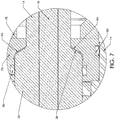
- any practical angle less than ninety degrees may be used for the angled faces 36 and the mating faces or seating surfaces of the outer housing and retainer ring. As noted above, this angle may be in the range of 40 to 75 degrees, and in one embodiment an angle of 60 degrees was used. Additionally, an intermediate layer 95 of softer material may be used in the seating area between the inclined shoulder and the opposing face of the housing or retainer ring 75, as illustrated in FIG. 7 . This creates a conformal load area to further minimize stress concentrations.
- the softer material may be copper, nickel, elastomeric material, or the like.
- the dual sliding pin arrangement of FIGS. 1 to 4 reduces the problems in manufacture of the penetrator assembly which result from the large differences in coefficients of thermal expansion of the conductive pin, ceramic body, and metal sealing sleeves.
- the high temperatures which arise during brazing of the metal seals to the ceramic body and the conductive pin, which is typically of copper or the like cause expansion of the copper pin.
- Subsequent cooling causes the copper pin to shrink, pulling and causing stress on the ceramic body at the bond between the metal sleeve and the body. This may make the bond brittle or cause it to break.
- This problem is avoided with the two part, telescopically engaging pin assembly of FIG. 1 to 4 , since the contacts can be assembled after metal seal brazing to the ceramic, and the telescoping ends of the pins can slide relative to one another to accommodate thermal expansion and contraction without producing stress on the seal bonds to the ceramic body.
- Typical penetrators are designed to have high pressure acting on one end only.
- the arrangement of FIGS. 1 to 4 is designed to accommodate high pressure at both ends of the penetrator.
- the different stiffness or elastic modulus of the materials of the conductive pin, ceramic body, and metal sealing sleeves can potentially create relative movement and stress on the seals in a typical penetrator when under pressure.
- the slidable arrangement of the above embodiment avoids such problems, lowering the stress between the conductors and the ceramic body.
- the brazed and welded sealing sleeves which are secured to the respective conductor halves or pins are configured so as to increase their sealing contact pressure or effectiveness with increased pressure.
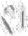
- FIGS. 10 to 12 Another embodiment of a penetrator pin assembly or subassembly 100 which may be assembled in housing 12 in place of assembly 10 is illustrated in FIGS. 10 to 12 .
- the outer ceramic body is identical to that of the previous embodiments, and like reference numbers are used for like parts as appropriate.
- the dual conductor arrangement is different.
- a solid conductor pin 102 extends into one end of bore 15 which extends through dielectric outer body or housing 14, and has an inner end attached to a flexible cable or flexible conductor 105 which extends up to the opposite end of bore 15. Opposite ends of flexible cable 105 are crimped or soldered in a bore 106 at the inner end of pin 102 and to an end cap 108, respectively.
- End cap 108 is welded or otherwise secured to a cable connector 110, and an outer, conductive sealing sleeve 112 extends between connector 110 and an opposing recessed end face 113 of the ceramic body 14.
- Metallic J-shaped sealing sleeves 114, 115 are brazed at opposite ends of the ceramic body 14, as in the first embodiment, with sleeve 114 brazed to the first end of ceramic body 14 and sleeve 115 brazed to the second end.
- Sleeve 114 is welded to the adjacent outer surface of conductor pin 102, while sleeve 115 is welded to the outer surface of sleeve 112.
- a second cable connector 116 is secured to the outer end of pin 102.
- FIGS. 13 and 14 illustrate a modified electrical penetrator or penetrator module 120 which is similar to the arrangement of FIGS. 1 to 5 but has a modified metal seal arrangement between the ceramic body and the respective conductor pins, which replaces the J-shaped and Z-shaped seals of FIGS. 3 and 5 .
- the end or tip 121 of one or both conductors is designed to be wet-mateable with a corresponding socket of a mating connector unit.
- one of the conductors 16 terminates in a rounded tip 121 designed for mating engagement in a corresponding socket, while the other conductor 18 terminates with an integral or separate cable connector 28, as described above in connection with FIGS. 1 to 5 .
- the ceramic body in this embodiment has a slightly different external shape from that of the previous embodiments, to accommodate the modified metal seal arrangement, as described in more detail below.
- the penetrator module is otherwise similar or identical to that of FIGS. 1 to 5 , and like reference numbers are used for like parts as appropriate.
- a straight or "flat" cylindrical sealing sleeve 122 is brazed onto the ceramic body 314 at each end of the penetrator, and the respective conductor rods 16, 18 are subsequently welded or brazed onto the cylindrical sleeve 122, as best illustrated in FIG. 14 .
- the respective ends of the ceramic body 314 and adjacent portions of the conductors 16, 18 are of corresponding outer diameter.
- Recessed areas 123,124 at the abutting ends of the respective conductor rod or pin 16, 18 and the adjacent end of the ceramic body 314 are provided for seating the sealing sleeves 122 so that the transition from conductor to sealing sleeve to ceramic is completely flush, as best illustrated in FIG. 14 .
- the ceramic body 314 therefore has a slightly different external shape from the previous embodiment, with a central, larger diameter portion 235 and opposite end portions 220, 222 of progressively stepped diameter extending from each end of central portion 235.
- End portions 222 may be of the same diameter, or of different diameters as seen in FIG. 13 , depending on the diameter of the abutting end portion 121 or 223, respectively, of conductors 16 and 18.
- the flat sealing sleeve arrangement of FIGS. 13 and 14 has an advantage over any non-flat geometry such as a J or Z shaped sleeve, due to the flush mounting of the metal sealing sleeves.
- the resultant uniform outer diameters of the pin, sealing sleeve, and ceramic outer body allow the penetrator assembly to be wet-mateable, i.e. it can enter a standard receptacle unit, such as the traditional stopper assembly of a Nautilus ® receptacle, and can interface with the sealing surfaces of the receptacle unit. If the penetrator pin has a sealing sleeve with a J- or Z geometry, it is not able to create a uniform seal with a receptacle unit sealing surface.
- FIG. 15 illustrates an electrical penetrator or penetrator assembly 125 according to another embodiment in which the two conductors which engage in a telescoping motion in the ceramic body through bore as in the first embodiment are replaced by conductor members comprising a fixed conductive socket member 126 at one end of the penetrator and a single conductor or conductor pin 128 having a reduced diameter end portion 130 extending into the socket 132 in socket member 126 with an expansion space or gap 135 between the inner end of conductor 128 and the end of socket or bore 132.
- This arrangement provides for a small amount of relative movement between the conductor 128 and socket to compensate for changes in conductor geometry due to different coefficients of thermal expansion of the different components of the penetrator.
- a sliding contact band between the end portion 130 an socket 132 may be provided, as in the first embodiment.
- a flat or cylindrical sealing sleeve 134 extends over the abutting end portions of the socket member 126 and ceramic body 314, and is welded or brazed to the underlying end portion of the socket member 126 and ceramic body 314.
- the abutting end portions of the socket member 126 and ceramic body 314 are also recessed to accommodate the thickness of sealing sleeve 134, so that sleeve 134 is flush or at least substantially flush with adjacent surfaces of socket member 126 and ceramic body 314.
- the single conductor 128 extends out of the ceramic insulator body at one end of the penetrator and into the socket 132, while the socket member rather than the conductor is brazed or welded to the end of the ceramic insulator body.
- FIG. 16 illustrates another modified penetrator assembly 140 which has a single conductor rod 142 extending through ceramic body 144 which is similar in shape to the ceramic insulator body or housing 314 of the previous embodiments, and like reference numbers have been used for like parts.
- Ceramic body 144 has opposite end portions 222 and 225 of different external diameters and lengths, with end portion 222 being longer and of smaller diameter than end portion 225.
- the conductor rod 142 projects out of the first end portion at one end and terminates in a conductor probe or tip 121, as in the embodiment of FIG. 14 , and is secured to the first end portion 222 of ceramic body 144 via flat or cylindrical sealing sleeve 122.
- the opposite end 145 of rod 142 terminates at the end of second end portion 225 of the ceramic body 144.
- a second conductor member comprising a conductive socket member or cable end connector 146 is secured to end portion 225 of ceramic body 144 via flat or cylindrical sealing sleeve 147 and has a socket or bore 148 facing conductor end 145.
- a coil spring 150 of conductive material is seated in bore 148 and bears against conductor end 145.
- the metal coil spring 150 thus extends between the two conductor portions, i.e. between conductor rod 142 and end connector or socket member 146, and acts to transfer electrical signals between the two conductor pieces as well as to allow relative movement between the conductor portions. It will be understood that a similar coil spring arrangement may be provided between two conductors or conductor rods which engage in the through bore of the ceramic insulator, as in the embodiment of FIGS. 1 to 5 .
- FIG. 17 illustrates a modification of the embodiment of FIG. 16 in which the coil spring 150 is replaced by a wave spring 152 of conductive material.
- the conductor rod 142 has a reduced diameter end portion 154 which extends into socket 148 to engage one end of wave spring 152.
- the components of the penetrator assembly of FIG. 17 are otherwise identical to those of FIG. 16 , and like reference numbers are used for like parts as appropriate.
- Either a coil spring or a wave spring may be used in either of the embodiments of FIG. 16 and 17 , and springs may also be used in the same manner between the inner ends of the conductors in the two conductor arrangement of FIGS. 1 to 5 , in place of the telescoping pin and socket arrangement of that embodiment.
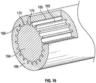
- FIG. 18 and 19 illustrate an electrical penetrator assembly 160 according to another embodiment with a different interface between two conductor members to allow for some relative movement while still maintaining electrical communication between the conductor members or pieces.
- penetrator assembly 160 has a first conductor member or single conductor rod extending through the insulator body 144 which has a projection 162 at one end of body 144 with a reduced diameter end portion 164 having a series of axially extending, radially projecting ribs or prongs 165 at spaced intervals around its circumference.
- a second conductor member or conductive cable end connector 166 has a mating socket 168 with a corresponding set of axially extending, radially extending grooves 170 configured for slidable, mating engagement with the radially configured ribs 165, as illustrated in FIG. 19 .
- the telescopic engagement between the conductor end portion and conductive socket member 168 allows for relative axial movement between the conductor pieces 162, 166, while the engagement of ribs 165 in radial grooves 170 allows the conductors to remain in electrical communication regardless of any radial contraction or expansion.
- this embodiment allows for both radial and axial contraction or expansion of the parts.
- the second conductor member or portion 166 is outside the ceramic insulator body and comprises a cable end connector.
- the same mating end portions may be provided between two conductor rods which extend into opposite ends of the through bore in the ceramic insulator body, in place of the cylindrical pin and socket arrangement of FIGS. 1 to 5 .
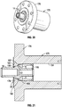
- FIG. 20 and 21 illustrate hermetic sealing of the ceramic insulator body or housing 14 (or 144) of the penetrator or penetrator assembly of any of the preceding embodiments to an outer housing 175 which has a flange 176 which may be bolted to a bulkhead or wall of a subsea vessel or container, or the like.
- insulator body 14 extends through a reduced diameter opening 178 in an outer end of housing 175, and is secured in the opening between a shoulder portion 180 of opening 178 engaging one side of the enlarged portion 35 of the insulator body and a retainer plate 182 engaging the opposite side of enlarged portion 35 inside the housing through bore 184.
- Retainer plate 182 is held in place by retainer nut 185.
- Opposing inner faces of shoulder portion 180 and retainer plate 182 are shaped to conform to the opposite tapering surfaces 36 of enlarged portion 35 of the insulator body (or to the corresponding tapering surfaces of enlarged portion 235 of the insulator body 314 or 144 of FIGS. 13 to 19 ).
- the ceramic insulator body 14 is welded and sealed to the penetrator housing 175 using two J-sleeve joints 186, 188.
- the first J-sleeve joint 186 is welded to the housing 175 and brazed to the ceramic insulator body 14 at the outer end of opening 178.
- the second J-sleeve joint 188 is welded or brazed to an indented or stepped portion 190 of the housing through bore in front of retainer plate 182, and brazed to the enlarged portion 35 of the insulator body at 191, as illustrated in FIG. 21 .
- Each J-sleeve joint is designed to withstand unidirectional pressure, and the two joints provide a hermetic seal between the housing and ceramic body.
- the J-sleeve joints provide sealing in opposite directions.
- FIG. 22 shows an alternative joint arrangement for sealing a penetrator assembly in an outer housing 195.
- the penetrator or penetrator assembly 125 of FIG. 15 is secured in housing 195, but the penetrators of any of the other embodiments described above could be secured in an outer housing with the same joint arrangement.
- enlarged portion 235 of ceramic insulator body 314 is held in the housing between opposing retainer plates 196, 197 which engage opposite ends of enlarged portion 235, with the first retainer plate 196 extending between shoulder 198 of the housing through bore and opposing plate 197, and the second retainer plate held in the bore by end nut or fastener 199.
- Z-sleeve joint 200 has a first portion 202 brazed to the largest diameter portion 235 of the ceramic body 314, and a second portion 200 brazed or welded to the housing retainer plate 196.
- This Z-sleeve joint is capable of withstanding bidirectional pressure. If the differential pressure is greater in one direction than the other, it is better to have the higher pressure acting on the "open" end of the Z-sleeve, so that the sleeve is forced into the housing rather than pushed out of it. Thus, in the illustrated embodiment, the maximum pressure gradient acts in the direction of arrow A.
- FIGS. 23 and 24 illustrate a modification of the penetrator or penetrator assemblies of the previous embodiments to include an electrical insulation bushing 210 at one end of the penetrator.
- bushing 210 is mounted at one end of penetrator 10 of FIGS. 1 to 5 , but it will be understood that a similar bushing may be provided on any of the alternative penetrator assemblies of FIGS. 8 to 20 in other embodiments.
- the bushing 210 may be located on the end of the penetrator located in a fluid-filled housing or potentially in other environments, and bushings 210 may be provided at both ends of the penetrator in some embodiments. As best illustrated in FIG.
- bushing 210 extends over the reduced diameter end portion 38 at one end of the ceramic body 14, but it may extend over the abutting ends of the ceramic body and conductor in embodiments with a flat sealing sleeve as in FIGS. 13 to 18 .
- Electrical insulation bushing 210 lengthens tracking distance between the charged conductor rod or rods inside the penetrator assembly and the ground plane that exists around the penetrator assembly.
- Bushing 210 has through bore 212 engaging over end portion 38 of the ceramic insulator body 14 and a wave-like outer geometry with ribs or ridges 214 which increases tracking distance over a relatively small axial distance.
- a hermetic electrical penetrator assembly is provided which is suitable for use in high temperature, high pressure, high voltage, and high current application, such as powering of subsea electrical submersible (ESP) pump equipment which is used to pump hydrocarbons in oil rig installations and the like.
- ESP electrical submersible
- Other applications for the penetrator assemblies in the above embodiments include high temperature, high pressure downhole electrical penetrations and other electrical penetrations used in subsea equipment of various types.
- the penetrator assemblies are scalable for a variety of current and voltage requirements.
- the penetrator assemblies of the above embodiments each include a two part conductor extending through the ceramic body which can move to accommodate different rates of thermal expansion and contraction as a result of extreme temperature changes
- the above designs lower stress under pressure extremes, and higher pressure on either side of the dual conductor assembly does not appreciably impact the conductor opposite the higher pressure side. This is an improvement over standard penetrator assemblies designed to have high pressure at one end only.
Landscapes
- Engineering & Computer Science (AREA)
- Architecture (AREA)
- Civil Engineering (AREA)
- Structural Engineering (AREA)
- Mining & Mineral Resources (AREA)
- Life Sciences & Earth Sciences (AREA)
- Geology (AREA)
- Environmental & Geological Engineering (AREA)
- Fluid Mechanics (AREA)
- Physics & Mathematics (AREA)
- General Life Sciences & Earth Sciences (AREA)
- Geochemistry & Mineralogy (AREA)
- Connections Arranged To Contact A Plurality Of Conductors (AREA)
- Connector Housings Or Holding Contact Members (AREA)
- Installation Of Indoor Wiring (AREA)
Claims (13)
- Elektrischer Penetrator (10, 100, 140), umfassend:ein Isolationsgehäuse (314) aus nichtleitendem Material, das eine Durchbohrung und ein gegenüberliegendes erstes und zweites Ende aufweist;einen ersten, langgestreckten elektrischen Leiter (16, 128, 142, 164), der sich durch zumindest einen Teil der Länge der Durchbohrung erstreckt und ein erstes Ende außerhalb eines ersten Endes des Isolationsgehäuses (314) und ein zweites Ende aufweist;einen zweiten elektrischen Leiter (18, 126, 146, 166), der ein erstes Ende und ein zweites Ende aufweist, wobei sich zumindest das zweite Ende des zweiten elektrischen Leiters außerhalb des zweiten Endes des Isolationsgehäuses (314) befindet;wobei das zweite Ende des ersten elektrischen Leiters (116, 128, 142, 164) in elektrischer Kommunikation mit dem ersten Ende des zweiten elektrischen Leiters (18, 126, 146, 166) steht und zumindest einer der Leiter bezogen auf den anderen Leiter bewegt werden kann, während eine elektrische Kommunikation zwischen den Leitern aufrechterhalten bleibt;wobei das Isolationsgehäuse (314) und der erste elektrische Leiter (16, 128, 142, 164) erste angrenzende Außenflächenabschnitte (124, 123) eines entsprechenden Durchmessers an dem ersten Ende des Isolationsgehäuses aufweisen;wobei das Isolationsgehäuse (314) und der zweite elektrische Leiter (18, 126, 146, 166) zweite angrenzende Außenflächenabschnitte (124, 123) eines entsprechenden Durchmessers an dem zweiten Ende des Isolationsgehäuses aufweisen;eine erste hermetische Dichtung aus leitendem Material, die sich zwischen dem ersten Ende des Isolationsgehäuses und dem ersten elektrischen Leiter erstreckt, und eine zweite hermetische Dichtung aus leitendem Material, die sich zwischen dem zweiten Ende des Isolationsgehäuses und dem zweiten elektrischen Leiter erstreckt;wobei die erste und zweite hermetische Dichtung eine erste und zweite zylindrische Hülse (122, 134, 147) umfassen, wobei die erste zylindrische Hülse über den ersten angrenzenden Außenflächenabschnitten (123, 124) des Isolationsgehäuses und des ersten Leiters befestigt ist und die zweite zylindrische Hülse über den zweiten angrenzenden Außenflächenabschnitten des Isolationsgehäuses und dem zweiten Leiter befestigt ist, wobei der erste und zweite Leiter eine Außenfläche aufweisen, die jeweils im Wesentlichen bündig mit benachbarten Außenflächenabschnitten des Isolationsgehäuses und dem ersten und zweiten Leiter sind;wobei jede zylindrische Hülse (122, 134, 147) eine Metallhülse ist, die an den Außenflächenabschnitt des entsprechenden Endes des Isolationsgehäuses (314) gelötet und an den Außenflächenabschnitt des entsprechenden elektrischen Leiters gelötet oder geschweißt ist.
- Penetrator (10, 100, 140) nach Anspruch 1, wobei die Außenflächenabschnitte (123, 124) des ersten und zweiten Leiters und des Isolationsgehäuses (14, 314) benachbart zu dem entsprechenden ersten und zweiten Ende des Außengehäuses bezogen auf benachbarte Außenflächenabschnitte des entsprechenden ersten und zweiten Leiters und des Isolationsgehäuses einen verringerten Durchmesser aufweisen, wobei die entsprechenden zylindrischen Metallhülsen (122, 134) in dem verringerten Durchmesser der Außenflächenabschnitte (123, 124) des Isolationsgehäuses und des entsprechenden Leiters sitzen und wobei jede zylindrische Metallhülse eine Außenfläche aufweist, die im Wesentlichen bündig mit benachbarten Außenflächenabschnitten des Isolationsgehäuses und des entsprechenden elektrischen Leiters benachbart zu den Abschnitten mit verringertem Durchmesser ist.
- Penetrator (10, 100, 140) nach Anspruch 1, wobei die erste und zweite hermetische Dichtung ein Legierungsmetall sind, das einen niedrigeren Wärmeausdehnungskoeffizienten aufweist als die Leiter.
- Penetrator (10, 100, 140) nach Anspruch 1, wobei der zweite Leiter (126, 146) einen Sockel (132, 148, 168) an dessen erstem Ende aufweist, der ein inneres Ende aufweist, und wobei der erste Leiter (128, 142) einen zweiten Endabschnitt (130, 164) aufweist, der teleskopartig in den Sockel eingreift, um eine relative Bewegung zwischen dem ersten und zweiten Leiter zu ermöglichen.
- Penetrator (10, 100, 140) nach Anspruch 4, ferner umfassend eine leitende Feder (150, 152), die in dem Sockel (132, 148, 168) zwischen dem zweiten Endabschnitt des ersten Leiters und dem inneren Ende des Sockels angebracht ist, wobei die leitende Feder eine Schraubenfeder (150) oder eine Wellenfeder (152) ist.
- Penetrator (10, 100, 140) nach Anspruch 4, wobei der zweite Endabschnitt (164) des ersten Leiters eine Vielzahl von sich axial erstreckenden, radial nach außen vorstehenden Rippen (165) aufweist und der Sockel (168) eine Vielzahl von passenden sich axial erstreckenden, radial nach innen vorstehenden Nuten (170) aufweist, die zum Passeingriff mit den Rippen konfiguriert sind, wenn der zweite Endabschnitt teleskopartig in den Sockel eingreift.
- Penetrator (10, 100, 140) nach Anspruch 1, wobei sich das zweite Ende des ersten Leiters (128, 142, 164) zumindest bis zu dem zweiten Ende des Isolationsgehäuses hinauf durch die Durchbohrung in dem Außengehäuse erstreckt und wobei das zweite Ende des ersten Leiters an dem zweiten Ende des Gehäuses oder außerhalb davon in elektrischer Kommunikation mit dem ersten Ende des zweiten Leiters (126, 146, 166) steht.
- Penetrator (10, 100, 140) nach Anspruch 7, wobei der zweite Leiter (126, 146, 166) ein leitendes Sockelelement umfasst, das zur Verbindung mit dem Ende eines Kabels konfiguriert ist, und das erste Ende des ersten Leiters zur Verbindung mit einem zweiten Kabel konfiguriert ist.
- Penetrator (10, 100, 140) nach Anspruch 7, wobei der zweite Leiter ein leitendes Sockelelement umfasst, das zur Verbindung mit dem Ende eines Kabels konfiguriert ist, und das erste Ende des ersten Leiters eine abgerundete leitende Spitze (121) aufweist, die zum lösbaren Passeingriff in einen leitenden Sockel in einer Aufnahmeverbindereinheit konfiguriert ist.
- Penetrator (10, 100, 140) nach Anspruch 1, ferner umfassend eine elektrische Isolationsbuchse (210), die sich an einem Ende des Gehäuses (14) zumindest über einen Teil des Isolationsgehäuses erstreckt, wobei die elektrische Isolationsbuchse eine wellenähnliche Außengeometrie aufweist, die konfiguriert ist, um die Verfolgungsentfernung zwischen dem ersten Leiter und einer Bodenplatte um den Penetrator zu erhöhen.
- Penetrator (10, 100, 140) nach Anspruch 1, ferner umfassend ein Penetratoraußengehäuse (175, 182, 195, 196, 197), das eine Durchbohrung aufweist;
wobei sich das Isolationsgehäuse (14, 314) durch zumindest einen Teil der Bohrung in dem Außenpenetratorgehäuse erstreckt; und zumindest eine hermetische Dichtungshülse (186, 188, 200) aus leitendem Material, die zwischen dem Isolationsgehäuse (14, 314) und dem Penetratoraußengehäuse (175, 182, 195, 196) befestigt ist. - Penetratorbaugruppe nach Anspruch 11, wobei die hermetische Dichtungshülse (186, 188, 200) J-förmig oder Z-förmig ist.
- Penetratorbaugruppe nach Anspruch 12, wobei das Penetratoraußengehäuse ferner eine Halteplatte (182, 196, 197) aus starrem Material umfasst, die in der Gehäusedurchbohrung befestigt ist und die das Isolationsgehäuse in dem Penetratorgehäuse hält, wobei die Halteplatte (182, 196, 197) eine Bohrung aufweist, durch die sich ein Teil des Isolationsgehäuses (14, 314) erstreckt.
Applications Claiming Priority (2)
| Application Number | Priority Date | Filing Date | Title |
|---|---|---|---|
| US13/786,203 US8968018B2 (en) | 2009-08-05 | 2013-03-05 | Electrical penetrator assembly |
| PCT/US2014/016810 WO2014137581A1 (en) | 2013-03-05 | 2014-02-18 | Electrical penetrator assembly |
Publications (3)
| Publication Number | Publication Date |
|---|---|
| EP2964879A1 EP2964879A1 (de) | 2016-01-13 |
| EP2964879A4 EP2964879A4 (de) | 2016-11-02 |
| EP2964879B1 true EP2964879B1 (de) | 2019-04-10 |
Family
ID=48780274
Family Applications (1)
| Application Number | Title | Priority Date | Filing Date |
|---|---|---|---|
| EP14760757.6A Active EP2964879B1 (de) | 2013-03-05 | 2014-02-18 | Elektrische penetratorbaugruppe |
Country Status (4)
| Country | Link |
|---|---|
| US (1) | US8968018B2 (de) |
| EP (1) | EP2964879B1 (de) |
| BR (1) | BR112015021152A8 (de) |
| WO (1) | WO2014137581A1 (de) |
Families Citing this family (29)
| Publication number | Priority date | Publication date | Assignee | Title |
|---|---|---|---|---|
| US8968018B2 (en) * | 2009-08-05 | 2015-03-03 | Teledyne Instruments, Inc. | Electrical penetrator assembly |
| US9951779B2 (en) | 2013-12-27 | 2018-04-24 | General Electric Company | Methods and systems for subsea boosting with direct current and alternating current power systems |
| US9912139B2 (en) * | 2014-03-03 | 2018-03-06 | Fmc Technologies, Inc. | Electrical penetrator assembly |
| US9941766B2 (en) * | 2014-04-04 | 2018-04-10 | Solar Turbines Incorporated | Penetrator power connector for an integrated rotary machine |
| WO2016004226A1 (en) * | 2014-07-02 | 2016-01-07 | Teledyne Instruments, Inc. | Non-pressure compensated, wet-mateable plug for feedthrough and other subsea systems |
| US10236622B2 (en) * | 2014-07-16 | 2019-03-19 | Siemens Aktiengesellschaft | Subsea electrical connector component |
| CN104538789B (zh) * | 2014-12-18 | 2017-01-18 | 中航光电科技股份有限公司 | 一种水下插拔连接器组件 |
| EP3070789A1 (de) * | 2015-03-17 | 2016-09-21 | Siemens Aktiengesellschaft | Leiteranordnung mit zwei leitenden kernteilen |
| US9774131B2 (en) * | 2015-12-22 | 2017-09-26 | Teledyne Instruments, Inc. | Fire-resistant electrical feedthrough |
| US10704353B2 (en) | 2015-12-22 | 2020-07-07 | Teledyne Instruments, Inc. | Modular electrical feedthrough |
| US10109949B2 (en) * | 2015-12-28 | 2018-10-23 | Teledyne Instruments, Inc. | Radially and axially-compressed ceramic sealing method and apparatus |
| US9812234B2 (en) * | 2016-03-04 | 2017-11-07 | Teledyne Scientific & Imaging, Llc | Hermetically sealed electrical penetrator assembly |
| GB201609468D0 (en) | 2016-05-30 | 2016-07-13 | Rmspumptools Ltd | Apparatus and method |
| EP3252894A1 (de) * | 2016-05-30 | 2017-12-06 | Siemens Aktiengesellschaft | Eindringvorrichtung für hochdruckanwendung |
| US10677030B2 (en) | 2016-08-22 | 2020-06-09 | Saudi Arabian Oil Company | Click together electrical submersible pump |
| US10249980B2 (en) | 2016-12-19 | 2019-04-02 | Teledyne Instruments, Inc. | Deformable translatable seat for reducing stress on ceramic penetrators |
| PT3549214T (pt) * | 2016-12-21 | 2022-05-05 | Balmoral Comtec Ltd | Dispositivo de interface de fundação com proteção de catodo |
| US10865627B2 (en) | 2017-02-01 | 2020-12-15 | Saudi Arabian Oil Company | Shrouded electrical submersible pump |
| NO342996B1 (en) * | 2017-03-17 | 2018-09-24 | Vetco Gray Scandinavia As | Electrical penetrator assembly |
| US10530143B2 (en) | 2017-09-21 | 2020-01-07 | Accessesp Uk Limited | Stress control cones for downhole electrical power system tubing encapsulated power cables |
| US10461464B1 (en) * | 2019-02-12 | 2019-10-29 | Spawar Systems Center Pacific | Bi-directional, rotating, pressure bulkhead penetrator |
| US11828126B2 (en) | 2019-02-20 | 2023-11-28 | Fmc Technologies, Inc. | Electrical feedthrough system and methods of use thereof |
| WO2021102145A1 (en) * | 2019-11-21 | 2021-05-27 | Avx Corporation | Wire termination device for coupling a wire to a feedthrough device and system including the same |
| WO2021257081A1 (en) * | 2020-06-18 | 2021-12-23 | Halliburton Energy Services, Inc. | Pressure isolation across a conductor |
| US11820474B2 (en) * | 2020-10-14 | 2023-11-21 | Aqua Satellite, Inc. | Feedthroughs for enclosures in deep water vessels |
| US12224521B2 (en) * | 2022-01-26 | 2025-02-11 | Onesubsea Ip Uk Limited | Subsea electrical connector |
| US11995085B2 (en) * | 2022-02-25 | 2024-05-28 | Visa International Service Association | System, method, and computer program product for efficiently storing multi-threaded log data |
| JP7457867B1 (ja) * | 2023-01-18 | 2024-03-28 | 長野工業株式会社 | 高所作業車 |
| NO348563B1 (en) * | 2023-06-13 | 2025-03-10 | Benestad Solutions As | High-voltage subsea assembly |
Family Cites Families (104)
| Publication number | Priority date | Publication date | Assignee | Title |
|---|---|---|---|---|
| US2740098A (en) | 1952-05-07 | 1956-03-27 | Titeflex Inc | Shielded waterproof electrical connectors |
| US2758291A (en) | 1952-09-10 | 1956-08-07 | Kingston Products Corp | Waterproof connector |
| US2700140A (en) | 1953-06-26 | 1955-01-18 | Titeflex Inc | Shielded, multiconductor waterproof connector |
| US3007130A (en) * | 1956-08-13 | 1961-10-31 | Technology Instr Corp Of Acton | Hermetically sealed electrical connector |
| US3092431A (en) | 1960-03-14 | 1963-06-04 | Emerson Electric Mfg Co | Detachable plug connector for submersible apparatus |
| US3243756A (en) | 1963-04-09 | 1966-03-29 | Elastic Stop Nut Corp | Shielded electrical connection |
| US3158420A (en) | 1963-12-24 | 1964-11-24 | Le Roy O Olson | Underwater electrical connector |
| US3307137A (en) | 1965-05-27 | 1967-02-28 | Mc Graw Edison Co | Conductor termination |
| US3376541A (en) | 1966-03-11 | 1968-04-02 | Rfe Corp | Safe break terminator |
| US3471669A (en) | 1968-01-16 | 1969-10-07 | Chance Co Ab | Encapsulated switch assembly for underground electric distribution service |
| US3522576A (en) | 1968-04-26 | 1970-08-04 | James L Cairns | Underwater electrical connector |
| US3513425A (en) | 1969-05-21 | 1970-05-19 | Gen Electric | Modular electrical conductor termination system |
| US3643208A (en) | 1969-05-21 | 1972-02-15 | Dynamics Corp America | Underwater separable connector |
| US3587035A (en) | 1969-09-10 | 1971-06-22 | Gen Electric | Gas shield for loadbreak cable termination |
| US3559141A (en) | 1969-10-23 | 1971-01-26 | Gen Electric | Underground electric power cable fuse housing having a semi-conductive corona shield |
| US4099021A (en) | 1970-04-24 | 1978-07-04 | Amerace Corporation | Method of splicing high voltage shielded cables and splice connector therefor |
| US3656084A (en) | 1970-07-06 | 1972-04-11 | Amerace Esna Corp | Connector construction for high voltage shielded cables |
| US3670287A (en) | 1970-08-17 | 1972-06-13 | Westinghouse Electric Corp | Electrical connector assembly |
| GB1374812A (en) | 1971-02-04 | 1974-11-20 | British Petroleum Co | Electrical connector |
| US3678432A (en) | 1971-04-26 | 1972-07-18 | Gen Electric | Vented fuse module for underground power cable system |
| US3750088A (en) | 1971-09-23 | 1973-07-31 | Obrien D G Inc | High pressure electrical feed-through fitting |
| US3793608A (en) | 1972-05-01 | 1974-02-19 | S Ring | Electrical connectors and method of making same |
| US3818407A (en) | 1972-09-25 | 1974-06-18 | Amerace Esna Corp | High voltage fuse enclosure |
| US3898731A (en) | 1973-05-01 | 1975-08-12 | Sandiford Ring | Method of making electrical connectors |
| US3816641A (en) | 1973-05-14 | 1974-06-11 | Viking Industries | Underwater connector and method of making same |
| US3982812A (en) | 1973-10-01 | 1976-09-28 | General Electric Company | Power cable separable connector having gasket means for restricting the flow of arc-generated gases therefrom |
| GB1526397A (en) | 1974-10-08 | 1978-09-27 | Raychem Ltd | Heat-recoverable article suitable for high voltage use |
| US3952218A (en) | 1974-10-29 | 1976-04-20 | Weil-Mclain Co., Inc. | Grounded electrical connector for submersible apparatus |
| US3992567A (en) | 1974-11-25 | 1976-11-16 | Amerace Corporation | Internal stress-grading system for electrical connections |
| US4006288A (en) | 1974-12-30 | 1977-02-01 | Amerace Corporation | High voltage shielded cable termination, splice connection, and method of making a splice connection |
| US3994552A (en) | 1975-10-01 | 1976-11-30 | International Telephone And Telegraph Corporation | Submersible pipe electrical cable assembly |
| US4032205A (en) | 1976-09-10 | 1977-06-28 | Rte Corporation | Adaptor for a high voltage cable |
| US4174145A (en) | 1976-12-29 | 1979-11-13 | The United States Of America As Represented By The United States Department Of Energy | High pressure electrical insulated feed thru connector |
| US4142770A (en) | 1977-12-27 | 1979-03-06 | Exxon Production Research Company | Subsea electrical connector |
| US4383131A (en) | 1978-09-14 | 1983-05-10 | Raychem Limited | Shielded electrical cable joints and terminations and sleeve and method for forming same |
| US4181175A (en) * | 1978-09-27 | 1980-01-01 | Combustion Engineering, Inc. | Control line exiting coupling |
| US4204739A (en) | 1978-11-13 | 1980-05-27 | Century Electric Motor Co. | Submersible electric motor and electrical connector assembly |
| US4266844A (en) | 1979-08-20 | 1981-05-12 | Bolt Associates, Inc. | High strength submersible electrical cable and connector assembly |
| US4334729A (en) | 1980-02-11 | 1982-06-15 | Kortech Engineering, Inc. | Penetrator assembly |
| FR2484162A1 (fr) | 1980-06-05 | 1981-12-11 | Cables De Lyon Geoffroy Delore | Dispositif de raccordement etanche d'un cable coaxial sous-marin a un repeteur, procede de fabrication de ce dispositif et moule utilisable dans ce procede |
| DE3380000D1 (en) | 1982-06-14 | 1989-07-06 | Raychem Corp | Shielded electric components |
| US4797117A (en) | 1982-12-23 | 1989-01-10 | Shell Oil Company | Marine electrical plug |
| US5070597A (en) | 1985-07-19 | 1991-12-10 | Raychem Corporation | Tubular article |
| US5174765A (en) | 1986-05-14 | 1992-12-29 | Barvid Technology Inc. | Electrical connector having electrically conductive elastomer covered by insulating elastomer |
| FR2599192B1 (fr) | 1986-05-20 | 1988-10-28 | Total Petroles | Connecteur electrique immergeable |
| US4728296A (en) | 1986-09-05 | 1988-03-01 | Stamm Bradley C | Electrical adaptor for downhole submersible pump |
| US4854886A (en) * | 1986-09-29 | 1989-08-08 | Hubbell Incorporated | Electrical penetrator for hot, high pressure service |
| JP2585344B2 (ja) | 1988-02-13 | 1997-02-26 | 住友電気工業株式会社 | 電力用海底ケーブルの鉛被接続方法 |
| US4948377A (en) | 1988-02-18 | 1990-08-14 | Cairns James L | Submersible electrical connector |
| GB8803893D0 (en) * | 1988-02-19 | 1988-03-23 | Bicc Plc | Electrical connector |
| GB2222032B (en) | 1988-06-27 | 1992-09-23 | Shell Int Research | Electric connector having underwater mateable parts |
| US4874324A (en) | 1988-08-03 | 1989-10-17 | Westinghouse Electric Corp. | Underwater electrical connector |
| US4909751A (en) | 1988-09-20 | 1990-03-20 | The United States Of America As Represented By The Secretary Of The Navy | Underwater mateable electrical connector |
| US5015016A (en) | 1989-04-03 | 1991-05-14 | National Coupling Company, Inc. | Internal pressure loaded V-seal connector |
| US5051103A (en) | 1990-10-09 | 1991-09-24 | Hubbell Incorporated | Electrical coupling assembly for hot, high pressure service |
| US5193614A (en) | 1991-02-26 | 1993-03-16 | Otis Engineering Corporation | Cable anchor assembly |
| US5166477A (en) | 1991-05-28 | 1992-11-24 | General Electric Company | Cable and termination for high voltage and high frequency applications |
| EP0619855A1 (de) | 1992-09-04 | 1994-10-19 | Halliburton Company | Hydraulischer Entriegelungsapparat und Entriegelungsmethode |
| US5478970A (en) | 1994-02-03 | 1995-12-26 | D. G. O'brien, Inc. | Apparatus for terminating and interconnecting rigid electrical cable and method |
| US5493073A (en) * | 1994-05-31 | 1996-02-20 | Emerson Electric Co. | Insulating arrangement for a fused hermetic terminal assembly |
| US5942333A (en) | 1995-03-27 | 1999-08-24 | Texas Research Institute | Non-conductive coatings for underwater connector backshells |
| US5833490A (en) | 1995-10-06 | 1998-11-10 | Pes, Inc. | High pressure instrument wire connector |
| GB9520588D0 (en) | 1995-10-09 | 1995-12-13 | Raychem Sa Nv | Corrosion protection and electrical grounding |
| US5700161A (en) | 1995-10-13 | 1997-12-23 | Baker Hughes Incorporated | Two-piece lead seal pothead connector |
| US5808258A (en) | 1995-12-26 | 1998-09-15 | Amerace Corporation | Encapsulated high voltage vacuum switches |
| US6475008B1 (en) | 1996-06-24 | 2002-11-05 | The United States Of America As Represented By The Secretary Of The Navy | Underwater mateable electrical connector with anti-hydrolock feature |
| US5899765A (en) | 1997-04-04 | 1999-05-04 | Lockheed Martin Services, Inc. | Dual bladder connector |
| US5938624A (en) | 1997-09-10 | 1999-08-17 | Radi Medical Systems Ab | Male connector with a continous surface for a guide wire and method therefor |
| GB2331871A (en) | 1997-11-28 | 1999-06-02 | Asea Brown Boveri | Insulated electrical conductor for high voltage use |
| GB9826630D0 (en) * | 1998-10-30 | 1999-01-27 | Expro North Sea Ltd | Electrical connector system |
| US6139354A (en) | 1999-06-14 | 2000-10-31 | Broussard; Blaine L. | Cable computer termination connector and sealing method |
| US6443780B2 (en) | 1999-08-23 | 2002-09-03 | Baker Hughes Incorporated | Conductor assembly for pothead connector |
| US6315461B1 (en) | 1999-10-14 | 2001-11-13 | Ocean Design, Inc. | Wet mateable connector |
| CN1398449A (zh) | 2000-02-09 | 2003-02-19 | Nkt电缆有限公司 | 电缆终端 |
| US6328615B1 (en) * | 2000-03-02 | 2001-12-11 | Itt Manufacturing Enterprises, Inc. | Contact formed of joined pieces |
| US6796829B1 (en) | 2000-03-03 | 2004-09-28 | Centerpin Technology, Inc. | Electrical connector apparatus and method |
| US6659780B2 (en) | 2000-04-14 | 2003-12-09 | Tronic Limited | Underwater connector with electrical stress reduction |
| US6397945B1 (en) | 2000-04-14 | 2002-06-04 | Camco International, Inc. | Power cable system for use in high temperature wellbore applications |
| US6332787B1 (en) | 2000-08-18 | 2001-12-25 | Ocean Design, Inc. | Wet-mateable electro-optical connector |
| US6537091B2 (en) | 2000-11-28 | 2003-03-25 | Autonetworks Technologies, Ltd. | Arc discharge suppressive terminal, method for producing such terminal, and arc discharge suppressive connector |
| GB2370427A (en) | 2000-12-20 | 2002-06-26 | Diamould Ltd | Electrical cable connector with gel to prevent bending of cable cores |
| US6464523B1 (en) | 2001-05-18 | 2002-10-15 | Northrop Grumman Corporation | Watertight electrical cable connector |
| US6921297B2 (en) | 2002-02-08 | 2005-07-26 | Emerson Electric Co. | Hermetic terminal assembly and associated method of manufacture |
| JP2003243101A (ja) | 2002-02-14 | 2003-08-29 | Nok Corp | コネクタ |
| US6628024B1 (en) * | 2002-07-30 | 2003-09-30 | Honeywell International, Inc. | Hermetically sealed feed-through assembly for gas turbine engine starter generators and related methods |
| KR100593468B1 (ko) | 2002-09-27 | 2006-06-26 | 주식회사 케이티 | 공중망에서의 네트워킹 pc 서비스 장치 및 제공 방법 |
| CN100459343C (zh) | 2002-12-16 | 2009-02-04 | 三菱电机株式会社 | 绝缘母线系统及其母线单元的连接方法 |
| US6821145B1 (en) * | 2003-07-16 | 2004-11-23 | Special Hermetic Products, Inc. | Hermetically sealed connector and methods of providing the same |
| US7059900B2 (en) | 2004-07-06 | 2006-06-13 | Holliday Randall A | Coaxial cable splice connector assemblies |
| US7645161B2 (en) | 2004-08-27 | 2010-01-12 | International Communication Manufacturing Corp. | Mini-coaxial cable connector assembly with interchargeable color bands |
| US7229325B1 (en) | 2005-07-29 | 2007-06-12 | Ilsco Corporation | Submersible electrical connector |
| GB2434698B (en) | 2006-01-26 | 2009-03-25 | Diamould Ltd | Contact pin assembly for a high voltage electrical connection |
| US7534147B2 (en) | 2006-07-14 | 2009-05-19 | Tronic Limited | Electrical connection apparatus |
| GB0708362D0 (en) | 2007-04-30 | 2007-06-06 | Tronic Ltd | Connector |
| US7794254B2 (en) | 2007-04-30 | 2010-09-14 | Tronic Limited | Submersible electrical connector |
| JP4922077B2 (ja) | 2007-06-15 | 2012-04-25 | 昭和電線ケーブルシステム株式会社 | 電気機器の通電部材およびこれを用いた電気機器の接続部 |
| US7718899B2 (en) | 2007-06-25 | 2010-05-18 | Harald Benestad | High pressure, high voltage penetrator assembly for subsea use |
| US7695301B2 (en) | 2008-08-07 | 2010-04-13 | Teledyne Odi, Inc. | Submersible connector with secondary sealing device |
| US7690936B1 (en) * | 2009-02-25 | 2010-04-06 | Octio Geophysical As | Subsea electrical penetrator |
| US7959454B2 (en) | 2009-07-23 | 2011-06-14 | Teledyne Odi, Inc. | Wet mate connector |
| US8968018B2 (en) * | 2009-08-05 | 2015-03-03 | Teledyne Instruments, Inc. | Electrical penetrator assembly |
| EP2462312B1 (de) | 2009-08-05 | 2022-08-17 | Teledyne Instruments, Inc. | Elektrische penetratorbaugruppe |
| FR2952245B1 (fr) | 2009-11-02 | 2011-12-09 | Carrier Kheops Bac | Systeme de transmission de puissance electrique a travers une paroi |
| US8638273B2 (en) * | 2011-02-16 | 2014-01-28 | General Electric Company | Antenna seal assembly and method of making the same |
-
2013
- 2013-03-05 US US13/786,203 patent/US8968018B2/en active Active
-
2014
- 2014-02-18 WO PCT/US2014/016810 patent/WO2014137581A1/en not_active Ceased
- 2014-02-18 BR BR112015021152A patent/BR112015021152A8/pt not_active Application Discontinuation
- 2014-02-18 EP EP14760757.6A patent/EP2964879B1/de active Active
Non-Patent Citations (1)
| Title |
|---|
| None * |
Also Published As
| Publication number | Publication date |
|---|---|
| BR112015021152A8 (pt) | 2019-12-03 |
| US8968018B2 (en) | 2015-03-03 |
| EP2964879A4 (de) | 2016-11-02 |
| EP2964879A1 (de) | 2016-01-13 |
| US20130183853A1 (en) | 2013-07-18 |
| BR112015021152A2 (pt) | 2017-07-18 |
| WO2014137581A1 (en) | 2014-09-12 |
Similar Documents
| Publication | Publication Date | Title |
|---|---|---|
| US8968018B2 (en) | Electrical penetrator assembly | |
| EP2462312B1 (de) | Elektrische penetratorbaugruppe | |
| US20200335899A1 (en) | Shock and Vibration Resistant Bulkhead Connector with Pliable Contacts | |
| EP2756567B1 (de) | Untersee-elektrosteckersystem für hohe temperaturen und hohen druck | |
| EP2316152B1 (de) | Hochdruck- und hochtemperaturabstandsbolzen für elektrischen steckverbinder in einem unterirdischen bohrloch | |
| EP3214704B1 (de) | Hermetisch abgedichtete elektrische durchführung und deren herstellungsverfahren | |
| US9853394B2 (en) | Pressure-blocking feedthru with pressure-balanced cable terminations | |
| US8382508B1 (en) | High voltage mechanical splice connector | |
| EP3271973B1 (de) | Leiteranordnung mit zwei leitenden kernteilen und verfahren zur montage und zum betrieb dafür | |
| NO340447B1 (no) | Koplingssammenstilling til bruk med en elektrisk neddykkbar komponent i et dypvannsmiljø | |
| EP3438408A1 (de) | Verbinderbaugruppe | |
| US9911564B2 (en) | Pressure-compensated fuse assembly | |
| EP3114741B1 (de) | Elektrische penetratorbaugruppe | |
| EP3152803B1 (de) | Steckerteil einer verbindungseinheit |
Legal Events
| Date | Code | Title | Description |
|---|---|---|---|
| PUAI | Public reference made under article 153(3) epc to a published international application that has entered the european phase |
Free format text: ORIGINAL CODE: 0009012 |
|
| 17P | Request for examination filed |
Effective date: 20151005 |
|
| AK | Designated contracting states |
Kind code of ref document: A1 Designated state(s): AL AT BE BG CH CY CZ DE DK EE ES FI FR GB GR HR HU IE IS IT LI LT LU LV MC MK MT NL NO PL PT RO RS SE SI SK SM TR |
|
| AX | Request for extension of the european patent |
Extension state: BA ME |
|
| DAX | Request for extension of the european patent (deleted) | ||
| REG | Reference to a national code |
Ref country code: DE Ref legal event code: R079 Ref document number: 602014044490 Country of ref document: DE Free format text: PREVIOUS MAIN CLASS: E21B0043110000 Ipc: H01R0013523000 |
|
| A4 | Supplementary search report drawn up and despatched |
Effective date: 20161004 |
|
| RIC1 | Information provided on ipc code assigned before grant |
Ipc: E21B 43/11 20060101ALI20160927BHEP Ipc: H01R 13/523 20060101AFI20160927BHEP Ipc: E21B 7/28 20060101ALI20160927BHEP |
|
| STAA | Information on the status of an ep patent application or granted ep patent |
Free format text: STATUS: EXAMINATION IS IN PROGRESS |
|
| 17Q | First examination report despatched |
Effective date: 20170803 |
|
| GRAP | Despatch of communication of intention to grant a patent |
Free format text: ORIGINAL CODE: EPIDOSNIGR1 |
|
| STAA | Information on the status of an ep patent application or granted ep patent |
Free format text: STATUS: GRANT OF PATENT IS INTENDED |
|
| INTG | Intention to grant announced |
Effective date: 20181031 |
|
| GRAS | Grant fee paid |
Free format text: ORIGINAL CODE: EPIDOSNIGR3 |
|
| GRAA | (expected) grant |
Free format text: ORIGINAL CODE: 0009210 |
|
| STAA | Information on the status of an ep patent application or granted ep patent |
Free format text: STATUS: THE PATENT HAS BEEN GRANTED |
|
| AK | Designated contracting states |
Kind code of ref document: B1 Designated state(s): AL AT BE BG CH CY CZ DE DK EE ES FI FR GB GR HR HU IE IS IT LI LT LU LV MC MK MT NL NO PL PT RO RS SE SI SK SM TR |
|
| REG | Reference to a national code |
Ref country code: GB Ref legal event code: FG4D |
|
| REG | Reference to a national code |
Ref country code: CH Ref legal event code: EP Ref country code: AT Ref legal event code: REF Ref document number: 1119957 Country of ref document: AT Kind code of ref document: T Effective date: 20190415 |
|
| REG | Reference to a national code |
Ref country code: IE Ref legal event code: FG4D |
|
| REG | Reference to a national code |
Ref country code: DE Ref legal event code: R096 Ref document number: 602014044490 Country of ref document: DE |
|
| REG | Reference to a national code |
Ref country code: NL Ref legal event code: MP Effective date: 20190410 |
|
| REG | Reference to a national code |
Ref country code: LT Ref legal event code: MG4D Ref country code: NO Ref legal event code: T2 Effective date: 20190410 |
|
| REG | Reference to a national code |
Ref country code: AT Ref legal event code: MK05 Ref document number: 1119957 Country of ref document: AT Kind code of ref document: T Effective date: 20190410 |
|
| PG25 | Lapsed in a contracting state [announced via postgrant information from national office to epo] |
Ref country code: NL Free format text: LAPSE BECAUSE OF FAILURE TO SUBMIT A TRANSLATION OF THE DESCRIPTION OR TO PAY THE FEE WITHIN THE PRESCRIBED TIME-LIMIT Effective date: 20190410 |
|
| PG25 | Lapsed in a contracting state [announced via postgrant information from national office to epo] |
Ref country code: ES Free format text: LAPSE BECAUSE OF FAILURE TO SUBMIT A TRANSLATION OF THE DESCRIPTION OR TO PAY THE FEE WITHIN THE PRESCRIBED TIME-LIMIT Effective date: 20190410 Ref country code: SE Free format text: LAPSE BECAUSE OF FAILURE TO SUBMIT A TRANSLATION OF THE DESCRIPTION OR TO PAY THE FEE WITHIN THE PRESCRIBED TIME-LIMIT Effective date: 20190410 Ref country code: HR Free format text: LAPSE BECAUSE OF FAILURE TO SUBMIT A TRANSLATION OF THE DESCRIPTION OR TO PAY THE FEE WITHIN THE PRESCRIBED TIME-LIMIT Effective date: 20190410 Ref country code: PT Free format text: LAPSE BECAUSE OF FAILURE TO SUBMIT A TRANSLATION OF THE DESCRIPTION OR TO PAY THE FEE WITHIN THE PRESCRIBED TIME-LIMIT Effective date: 20190910 Ref country code: AL Free format text: LAPSE BECAUSE OF FAILURE TO SUBMIT A TRANSLATION OF THE DESCRIPTION OR TO PAY THE FEE WITHIN THE PRESCRIBED TIME-LIMIT Effective date: 20190410 Ref country code: FI Free format text: LAPSE BECAUSE OF FAILURE TO SUBMIT A TRANSLATION OF THE DESCRIPTION OR TO PAY THE FEE WITHIN THE PRESCRIBED TIME-LIMIT Effective date: 20190410 Ref country code: LT Free format text: LAPSE BECAUSE OF FAILURE TO SUBMIT A TRANSLATION OF THE DESCRIPTION OR TO PAY THE FEE WITHIN THE PRESCRIBED TIME-LIMIT Effective date: 20190410 |
|
| PG25 | Lapsed in a contracting state [announced via postgrant information from national office to epo] |
Ref country code: PL Free format text: LAPSE BECAUSE OF FAILURE TO SUBMIT A TRANSLATION OF THE DESCRIPTION OR TO PAY THE FEE WITHIN THE PRESCRIBED TIME-LIMIT Effective date: 20190410 Ref country code: RS Free format text: LAPSE BECAUSE OF FAILURE TO SUBMIT A TRANSLATION OF THE DESCRIPTION OR TO PAY THE FEE WITHIN THE PRESCRIBED TIME-LIMIT Effective date: 20190410 Ref country code: BG Free format text: LAPSE BECAUSE OF FAILURE TO SUBMIT A TRANSLATION OF THE DESCRIPTION OR TO PAY THE FEE WITHIN THE PRESCRIBED TIME-LIMIT Effective date: 20190710 Ref country code: LV Free format text: LAPSE BECAUSE OF FAILURE TO SUBMIT A TRANSLATION OF THE DESCRIPTION OR TO PAY THE FEE WITHIN THE PRESCRIBED TIME-LIMIT Effective date: 20190410 Ref country code: GR Free format text: LAPSE BECAUSE OF FAILURE TO SUBMIT A TRANSLATION OF THE DESCRIPTION OR TO PAY THE FEE WITHIN THE PRESCRIBED TIME-LIMIT Effective date: 20190711 |
|
| PG25 | Lapsed in a contracting state [announced via postgrant information from national office to epo] |
Ref country code: IS Free format text: LAPSE BECAUSE OF FAILURE TO SUBMIT A TRANSLATION OF THE DESCRIPTION OR TO PAY THE FEE WITHIN THE PRESCRIBED TIME-LIMIT Effective date: 20190810 Ref country code: AT Free format text: LAPSE BECAUSE OF FAILURE TO SUBMIT A TRANSLATION OF THE DESCRIPTION OR TO PAY THE FEE WITHIN THE PRESCRIBED TIME-LIMIT Effective date: 20190410 |
|
| REG | Reference to a national code |
Ref country code: DE Ref legal event code: R097 Ref document number: 602014044490 Country of ref document: DE |
|
| PG25 | Lapsed in a contracting state [announced via postgrant information from national office to epo] |
Ref country code: EE Free format text: LAPSE BECAUSE OF FAILURE TO SUBMIT A TRANSLATION OF THE DESCRIPTION OR TO PAY THE FEE WITHIN THE PRESCRIBED TIME-LIMIT Effective date: 20190410 Ref country code: DK Free format text: LAPSE BECAUSE OF FAILURE TO SUBMIT A TRANSLATION OF THE DESCRIPTION OR TO PAY THE FEE WITHIN THE PRESCRIBED TIME-LIMIT Effective date: 20190410 Ref country code: RO Free format text: LAPSE BECAUSE OF FAILURE TO SUBMIT A TRANSLATION OF THE DESCRIPTION OR TO PAY THE FEE WITHIN THE PRESCRIBED TIME-LIMIT Effective date: 20190410 Ref country code: SK Free format text: LAPSE BECAUSE OF FAILURE TO SUBMIT A TRANSLATION OF THE DESCRIPTION OR TO PAY THE FEE WITHIN THE PRESCRIBED TIME-LIMIT Effective date: 20190410 Ref country code: CZ Free format text: LAPSE BECAUSE OF FAILURE TO SUBMIT A TRANSLATION OF THE DESCRIPTION OR TO PAY THE FEE WITHIN THE PRESCRIBED TIME-LIMIT Effective date: 20190410 |
|
| PLBE | No opposition filed within time limit |
Free format text: ORIGINAL CODE: 0009261 |
|
| STAA | Information on the status of an ep patent application or granted ep patent |
Free format text: STATUS: NO OPPOSITION FILED WITHIN TIME LIMIT |
|
| PG25 | Lapsed in a contracting state [announced via postgrant information from national office to epo] |
Ref country code: SM Free format text: LAPSE BECAUSE OF FAILURE TO SUBMIT A TRANSLATION OF THE DESCRIPTION OR TO PAY THE FEE WITHIN THE PRESCRIBED TIME-LIMIT Effective date: 20190410 Ref country code: IT Free format text: LAPSE BECAUSE OF FAILURE TO SUBMIT A TRANSLATION OF THE DESCRIPTION OR TO PAY THE FEE WITHIN THE PRESCRIBED TIME-LIMIT Effective date: 20190410 |
|
| 26N | No opposition filed |
Effective date: 20200113 |
|
| PG25 | Lapsed in a contracting state [announced via postgrant information from national office to epo] |
Ref country code: TR Free format text: LAPSE BECAUSE OF FAILURE TO SUBMIT A TRANSLATION OF THE DESCRIPTION OR TO PAY THE FEE WITHIN THE PRESCRIBED TIME-LIMIT Effective date: 20190410 |
|
| PG25 | Lapsed in a contracting state [announced via postgrant information from national office to epo] |
Ref country code: SI Free format text: LAPSE BECAUSE OF FAILURE TO SUBMIT A TRANSLATION OF THE DESCRIPTION OR TO PAY THE FEE WITHIN THE PRESCRIBED TIME-LIMIT Effective date: 20190410 |
|
| REG | Reference to a national code |
Ref country code: CH Ref legal event code: PL |
|
| REG | Reference to a national code |
Ref country code: BE Ref legal event code: MM Effective date: 20200229 |
|
| PG25 | Lapsed in a contracting state [announced via postgrant information from national office to epo] |
Ref country code: LU Free format text: LAPSE BECAUSE OF NON-PAYMENT OF DUE FEES Effective date: 20200218 Ref country code: MC Free format text: LAPSE BECAUSE OF FAILURE TO SUBMIT A TRANSLATION OF THE DESCRIPTION OR TO PAY THE FEE WITHIN THE PRESCRIBED TIME-LIMIT Effective date: 20190410 |
|
| PG25 | Lapsed in a contracting state [announced via postgrant information from national office to epo] |
Ref country code: LI Free format text: LAPSE BECAUSE OF NON-PAYMENT OF DUE FEES Effective date: 20200229 Ref country code: CH Free format text: LAPSE BECAUSE OF NON-PAYMENT OF DUE FEES Effective date: 20200229 |
|
| PG25 | Lapsed in a contracting state [announced via postgrant information from national office to epo] |
Ref country code: IE Free format text: LAPSE BECAUSE OF NON-PAYMENT OF DUE FEES Effective date: 20200218 |
|
| PG25 | Lapsed in a contracting state [announced via postgrant information from national office to epo] |
Ref country code: BE Free format text: LAPSE BECAUSE OF NON-PAYMENT OF DUE FEES Effective date: 20200229 |
|
| PG25 | Lapsed in a contracting state [announced via postgrant information from national office to epo] |
Ref country code: MT Free format text: LAPSE BECAUSE OF FAILURE TO SUBMIT A TRANSLATION OF THE DESCRIPTION OR TO PAY THE FEE WITHIN THE PRESCRIBED TIME-LIMIT Effective date: 20190410 Ref country code: CY Free format text: LAPSE BECAUSE OF FAILURE TO SUBMIT A TRANSLATION OF THE DESCRIPTION OR TO PAY THE FEE WITHIN THE PRESCRIBED TIME-LIMIT Effective date: 20190410 |
|
| PG25 | Lapsed in a contracting state [announced via postgrant information from national office to epo] |
Ref country code: MK Free format text: LAPSE BECAUSE OF FAILURE TO SUBMIT A TRANSLATION OF THE DESCRIPTION OR TO PAY THE FEE WITHIN THE PRESCRIBED TIME-LIMIT Effective date: 20190410 |
|
| PGFP | Annual fee paid to national office [announced via postgrant information from national office to epo] |
Ref country code: GB Payment date: 20260219 Year of fee payment: 13 |
|
| PGFP | Annual fee paid to national office [announced via postgrant information from national office to epo] |
Ref country code: DE Payment date: 20260206 Year of fee payment: 13 Ref country code: NO Payment date: 20260127 Year of fee payment: 13 |
|
| PGFP | Annual fee paid to national office [announced via postgrant information from national office to epo] |
Ref country code: FR Payment date: 20260227 Year of fee payment: 13 |