EP2964887B1 - Procédé de formation d'un ensemble aile portante composite de moteur à turbine à gaz et ensemble aile portante correspondante - Google Patents
Procédé de formation d'un ensemble aile portante composite de moteur à turbine à gaz et ensemble aile portante correspondante Download PDFInfo
- Publication number
- EP2964887B1 EP2964887B1 EP13822051.2A EP13822051A EP2964887B1 EP 2964887 B1 EP2964887 B1 EP 2964887B1 EP 13822051 A EP13822051 A EP 13822051A EP 2964887 B1 EP2964887 B1 EP 2964887B1
- Authority
- EP
- European Patent Office
- Prior art keywords
- airfoil
- endwall
- locking component
- composite
- pressure side
- Prior art date
- Legal status (The legal status is an assumption and is not a legal conclusion. Google has not performed a legal analysis and makes no representation as to the accuracy of the status listed.)
- Not-in-force
Links
- 238000000034 method Methods 0.000 title claims description 30
- 239000002131 composite material Substances 0.000 title claims 18
- 239000000463 material Substances 0.000 claims description 27
- 239000000945 filler Substances 0.000 claims description 26
- 230000013011 mating Effects 0.000 claims description 15
- 238000001764 infiltration Methods 0.000 claims description 11
- 230000008595 infiltration Effects 0.000 claims description 11
- 239000000835 fiber Substances 0.000 claims description 5
- 238000003780 insertion Methods 0.000 claims 2
- 230000037431 insertion Effects 0.000 claims 2
- 239000011153 ceramic matrix composite Substances 0.000 description 39
- 230000008569 process Effects 0.000 description 12
- 238000000429 assembly Methods 0.000 description 3
- 230000000712 assembly Effects 0.000 description 3
- 239000011159 matrix material Substances 0.000 description 3
- 239000000126 substance Substances 0.000 description 3
- 230000008901 benefit Effects 0.000 description 2
- 239000000919 ceramic Substances 0.000 description 2
- 239000003999 initiator Substances 0.000 description 2
- 238000000626 liquid-phase infiltration Methods 0.000 description 2
- 230000007246 mechanism Effects 0.000 description 2
- 229920000642 polymer Polymers 0.000 description 2
- 239000002002 slurry Substances 0.000 description 2
- 230000004075 alteration Effects 0.000 description 1
- 238000009954 braiding Methods 0.000 description 1
- 239000011248 coating agent Substances 0.000 description 1
- 238000000576 coating method Methods 0.000 description 1
- 230000001419 dependent effect Effects 0.000 description 1
- 238000005516 engineering process Methods 0.000 description 1
- 239000004744 fabric Substances 0.000 description 1
- 238000009730 filament winding Methods 0.000 description 1
- 238000005470 impregnation Methods 0.000 description 1
- 239000007769 metal material Substances 0.000 description 1
- 238000012986 modification Methods 0.000 description 1
- 230000004048 modification Effects 0.000 description 1
- 230000001737 promoting effect Effects 0.000 description 1
- 230000003068 static effect Effects 0.000 description 1
- 238000011282 treatment Methods 0.000 description 1
Images


Classifications
-
- F—MECHANICAL ENGINEERING; LIGHTING; HEATING; WEAPONS; BLASTING
- F01—MACHINES OR ENGINES IN GENERAL; ENGINE PLANTS IN GENERAL; STEAM ENGINES
- F01D—NON-POSITIVE DISPLACEMENT MACHINES OR ENGINES, e.g. STEAM TURBINES
- F01D5/00—Blades; Blade-carrying members; Heating, heat-insulating, cooling or antivibration means on the blades or the members
- F01D5/12—Blades
- F01D5/14—Form or construction
- F01D5/147—Construction, i.e. structural features, e.g. of weight-saving hollow blades
-
- F—MECHANICAL ENGINEERING; LIGHTING; HEATING; WEAPONS; BLASTING
- F01—MACHINES OR ENGINES IN GENERAL; ENGINE PLANTS IN GENERAL; STEAM ENGINES
- F01D—NON-POSITIVE DISPLACEMENT MACHINES OR ENGINES, e.g. STEAM TURBINES
- F01D5/00—Blades; Blade-carrying members; Heating, heat-insulating, cooling or antivibration means on the blades or the members
- F01D5/12—Blades
- F01D5/28—Selecting particular materials; Particular measures relating thereto; Measures against erosion or corrosion
- F01D5/282—Selecting composite materials, e.g. blades with reinforcing filaments
-
- F—MECHANICAL ENGINEERING; LIGHTING; HEATING; WEAPONS; BLASTING
- F01—MACHINES OR ENGINES IN GENERAL; ENGINE PLANTS IN GENERAL; STEAM ENGINES
- F01D—NON-POSITIVE DISPLACEMENT MACHINES OR ENGINES, e.g. STEAM TURBINES
- F01D9/00—Stators
- F01D9/02—Nozzles; Nozzle boxes; Stator blades; Guide conduits, e.g. individual nozzles
- F01D9/04—Nozzles; Nozzle boxes; Stator blades; Guide conduits, e.g. individual nozzles forming ring or sector
- F01D9/042—Nozzles; Nozzle boxes; Stator blades; Guide conduits, e.g. individual nozzles forming ring or sector fixing blades to stators
- F01D9/044—Nozzles; Nozzle boxes; Stator blades; Guide conduits, e.g. individual nozzles forming ring or sector fixing blades to stators permanently, e.g. by welding, brazing, casting or the like
-
- F—MECHANICAL ENGINEERING; LIGHTING; HEATING; WEAPONS; BLASTING
- F05—INDEXING SCHEMES RELATING TO ENGINES OR PUMPS IN VARIOUS SUBCLASSES OF CLASSES F01-F04
- F05D—INDEXING SCHEME FOR ASPECTS RELATING TO NON-POSITIVE-DISPLACEMENT MACHINES OR ENGINES, GAS-TURBINES OR JET-PROPULSION PLANTS
- F05D2230/00—Manufacture
- F05D2230/60—Assembly methods
- F05D2230/64—Assembly methods using positioning or alignment devices for aligning or centring, e.g. pins
-
- F—MECHANICAL ENGINEERING; LIGHTING; HEATING; WEAPONS; BLASTING
- F05—INDEXING SCHEMES RELATING TO ENGINES OR PUMPS IN VARIOUS SUBCLASSES OF CLASSES F01-F04
- F05D—INDEXING SCHEME FOR ASPECTS RELATING TO NON-POSITIVE-DISPLACEMENT MACHINES OR ENGINES, GAS-TURBINES OR JET-PROPULSION PLANTS
- F05D2260/00—Function
- F05D2260/30—Retaining components in desired mutual position
- F05D2260/36—Retaining components in desired mutual position by a form fit connection, e.g. by interlocking
-
- F—MECHANICAL ENGINEERING; LIGHTING; HEATING; WEAPONS; BLASTING
- F05—INDEXING SCHEMES RELATING TO ENGINES OR PUMPS IN VARIOUS SUBCLASSES OF CLASSES F01-F04
- F05D—INDEXING SCHEME FOR ASPECTS RELATING TO NON-POSITIVE-DISPLACEMENT MACHINES OR ENGINES, GAS-TURBINES OR JET-PROPULSION PLANTS
- F05D2300/00—Materials; Properties thereof
- F05D2300/60—Properties or characteristics given to material by treatment or manufacturing
- F05D2300/601—Fabrics
- F05D2300/6012—Woven fabrics
-
- F—MECHANICAL ENGINEERING; LIGHTING; HEATING; WEAPONS; BLASTING
- F05—INDEXING SCHEMES RELATING TO ENGINES OR PUMPS IN VARIOUS SUBCLASSES OF CLASSES F01-F04
- F05D—INDEXING SCHEME FOR ASPECTS RELATING TO NON-POSITIVE-DISPLACEMENT MACHINES OR ENGINES, GAS-TURBINES OR JET-PROPULSION PLANTS
- F05D2300/00—Materials; Properties thereof
- F05D2300/60—Properties or characteristics given to material by treatment or manufacturing
- F05D2300/603—Composites; e.g. fibre-reinforced
- F05D2300/6033—Ceramic matrix composites [CMC]
-
- Y—GENERAL TAGGING OF NEW TECHNOLOGICAL DEVELOPMENTS; GENERAL TAGGING OF CROSS-SECTIONAL TECHNOLOGIES SPANNING OVER SEVERAL SECTIONS OF THE IPC; TECHNICAL SUBJECTS COVERED BY FORMER USPC CROSS-REFERENCE ART COLLECTIONS [XRACs] AND DIGESTS
- Y02—TECHNOLOGIES OR APPLICATIONS FOR MITIGATION OR ADAPTATION AGAINST CLIMATE CHANGE
- Y02T—CLIMATE CHANGE MITIGATION TECHNOLOGIES RELATED TO TRANSPORTATION
- Y02T50/00—Aeronautics or air transport
- Y02T50/60—Efficient propulsion technologies, e.g. for aircraft
-
- Y—GENERAL TAGGING OF NEW TECHNOLOGICAL DEVELOPMENTS; GENERAL TAGGING OF CROSS-SECTIONAL TECHNOLOGIES SPANNING OVER SEVERAL SECTIONS OF THE IPC; TECHNICAL SUBJECTS COVERED BY FORMER USPC CROSS-REFERENCE ART COLLECTIONS [XRACs] AND DIGESTS
- Y10—TECHNICAL SUBJECTS COVERED BY FORMER USPC
- Y10T—TECHNICAL SUBJECTS COVERED BY FORMER US CLASSIFICATION
- Y10T29/00—Metal working
- Y10T29/49—Method of mechanical manufacture
- Y10T29/49229—Prime mover or fluid pump making
Definitions
- the present application relates to gas turbine engine ceramic matrix composite vane assemblies and methods for forming same, and more particularly to multiple-component gas turbine engine CMC assemblies and methods for forming same.
- a CMC turbine vane is described in EP 1 367 037 .
- the airfoil member and platform member are formed separately and are then bonded together to form an integral vane component.
- a mechanical fastener and/or a CMC doubler may be utilized to reinforce the bonded joint.
- a CMC turbine stator vane is described in EP 2 412 929 .
- a blade is formed of CMC or metallic material and is supported by a band formed of CMC material. The blade and band both include fitting portions. A flexible wire is disposed between the fitting portions to fix the blade and the band.
- a method of joining ceramic parts is described in US 2005/0254942 .
- a first CMC element is fabricated and fired to a selected first cured state.
- a second CMC element is fabricated and left in a green state, or is fired to a second partially cured state that is less complete than that of the first cured state.
- the two CMC elements are joined in a mating interface that captures an inner joining portion of the second element within a surrounding outer joining portion of the first element.
- the assembled elements are then fired together.
- the present disclosure may comprise one or more of the following features and combinations thereof.
- One embodiment of the present disclosure is a unique method for forming a gas turbine engine ceramic matrix composite vane assembly in which, among other things, a locking component and/or mat filler material may be provided in a joint portion of the assembly.
- Other embodiments include unique methods, systems, devices, and apparatus for forming a CMC assembly. Further embodiments, forms, objects, aspects, benefits, features, and advantages of the present application shall become apparent from the description and figures provided herewith.
- a method for forming a gas turbine engine airfoil assembly is disclosed, as defined in claim 1.
- a gas turbine engine airfoil assembly formed by the method of claim 1 is provided, as defined in claim 9.
- a gas turbine engine airfoil assembly is provided, as defined in claim 10.
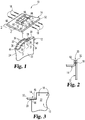
- FIG. 1 shows an exploded perspective view of an unclaimed example of a ceramic matrix composite (CMC) assembly 10.
- the CMC assembly 10 comprises components suitable for use in a gas turbine engine, although the CMC assembly 10 is not limited as such and other forms are contemplated herein.
- the CMC assembly 10 can comprise vanes and endwalls, cases with shields, or static flow components.
- the CMC assembly 10 can comprise ceramic matrix components for use in the hot section of a nuclear reactor.
- the CMC assembly 10 includes an upstanding airfoil 12, an endwall 14, locking components 18, and a mat filler material 20.
- the locking components 18 can lock together the airfoil 12 and endwall 14, and the mat filler material 20 can serve as a bond initiator and/or joint filler to accommodate for example misalignment and/or tolerance errors at the mating faces of the airfoil 12 and the endwall 14 or at the mating faces of the locking component 18 and the airfoil 12 and/or the endwall 14.
- the airfoil 12 and endwall 14 can be preform partially-rigidized or un-rigidized components.
- the components can be fabricated of woven or non-woven fiber.
- the fibers can be arranged and fixed by any suitable technique for example as by lay-up of fabrics, filament winding, braiding, knotting, or any combination of these.
- the components can be partially or fully densified, or partially or fully infiltrated so as to fill in one or more gaps between fibers of matrix material.
- the components can also be of near-net shape and/or machined and/or undergo further treatments such as coating or impregnation of the matrix material, in order to, for example, provide features that constrain the CMC assembly 10 when used in conjunction with one or more locking components 18.
- the CMC assembly 10 can be constructed of preform components having different configurations as necessary or desired for a particular application.
- the airfoil 12 and endwall 14 each comprise a preform, and are trimmed and machined.
- the airfoil 12 has a pressure side 22 and a suction side 24 that define a hollow 28 therebetween.
- a pair of airfoil connecting tabs 32, 34 can be formed and/or machined at one end 30 of the airfoil 12 to extend in the spanwise direction of the airfoil 12.
- the airfoil connecting tabs 32, 34 each have through holes 36 that are sized to receive the locking components 18, as will be described in greater detail below.
- One airfoil connecting tab 32 projects outwardly from and has substantially the same contour as the pressure side 22 of the airfoil 12.
- the other airfoil connecting tab 34 projects outwardly from and has substantially the same contour as the suction side 24 of the airfoil 12.
- the end 30 of the airfoil 12 can be configured to form a pair of seat portions 46, 48 that interface with the endwall 14 and/or the mat filler material 20.
- the endwall 14 includes a platform portion 52 having an opening 56 that is sized to receive therethrough the airfoil connecting tabs 32, 34.
- a pair of endwall connecting tabs 62, 64 can be formed and/or machined in the endwall 14 to correspond to the suction side 24 and pressure side 22 of the airfoil 12 in a state where the endwall 14 is assembled to the airfoil 12 in FIG. 1 .
- the endwall connecting tabs 62, 64 can correspond substantially in size and shape to the airfoil connecting tabs 32, 34 of the airfoil 12.
- the endwall connecting tabs 62, 64 can project in a manner that is upstanding relative to the platform portion 52 of the endwall 14 and substantially parallel relative to the airfoil connecting tabs 32, 34 of the airfoil 12.
- the platform portion 52 of the endwall 14 has cooperating surfaces 66, 68 (underside of the endwall 14 as shown in FIGS. 1 and 3 ) that rest upon or over the seat portions 46, 48, respectively, at the end 30 of the airfoil 12.
- the cooperative relationship between the cooperating surfaces 66, 68 and the seat portions 46, 48 resists or prevents the endwall 14 from translating down the airfoil 12, as would be the inclination in the instance where for example greater pressure is applied to the top side (as shown in FIG. 1 ) of the endwall 14 than the underside thereof.
- the endwall connecting tabs 62, 64 each have through holes 76 that are sized to receive the locking components 18.
- the locking components 18 pass through the through holes 36, 76 in the airfoil 12 and endwall 14.
- the locking components 18 lock the airfoil 12 into place relative to the endwall 14, preventing withdrawal of the airfoil 12 from the endwall 14 in the direction from which the airfoil 12 was inserted into the endwall 14, i.e. in the spanwise direction of the airfoil 12.
- the locking components 18 can take the form of locking pins, although the locking components 18 are not limited as such, and other embodiments are contemplated.
- the locking components 18 can be sized to fit into a feature such as a through-hole or cavity in and/or between one or more of the preform airfoil and endwall components.
- the locking components 18 can be substantially the same length as the combined thickness of the endwall connecting tab 62, the airfoil connecting tab 32, and the mat filler material 20 therebetween.
- the locking components 18 can be fabricated of braided woven or non-woven fiber. Further, the locking components 18 can be partially or fully densified.
- the locking components 18 can also be of near-net shape and/or machined in order to, for example, provide features that facilitate constraining the preform components of the CMC assembly 10. In FIG. 1 , for example, the locking components 18 each comprise a preform, and are trimmed and machined.
- a mat filler material 20 can be provided between the mating faces of the airfoil 12 and the endwall 14.
- the mat filler material 20 can be provided between the endwall connecting tab 62 of the endwall 14 and the airfoil connecting tab 32 of the airfoil 12.
- the mat filler material 20 can be provided between the cooperating surface 66 of the endwall 14 and the seat portion 46 of the airfoil 12.
- the mat filler material 20 can serve for example as a joint filler material and/or bond initiator during for example chemical vapor infiltration (CVI) processing.
- CVI chemical vapor infiltration
- the mat filler material 20 can comprise for example pre-cut pieces that substantially match for example the dimensions of the mating faces of the airfoil 12 and the endwall 14.
- the mat filler material 20 can be utilized for example to close unsuitable gaps between machined or near-net partially-rigidized components.
- the mat filler material 20 can be of non-woven material.
- the mat filler material 20 can be in its raw, unprocessed state.
- the mat filler material 20 can be of any thickness, or a varying thickness, that is necessary or desired for a particular application.
- FIG. 4 is a flowchart depicting steps of an exemplary unclaimed process for forming a CMC assembly.
- the airfoil 12 and endwall 14 preform components can be provided in their un-rigidized or partially-rigidized states (Step 80).
- the formed or machined airfoil connecting tabs 32, 34 can be pushed through the opening 56 in the endwall 14 so that the airfoil connecting tabs 32, 34 are alongside the endwall connecting tabs 62, 64, as shown for example in FIG. 2 , and the cooperating surfaces 66, 68 of the endwall 14 rest over or upon the seat portions 46, 48 of the airfoil 12, as shown for example in FIG. 3 .
- the mat filler material 20 can be placed between the mating faces of the airfoil 12 and endwall 14, for example between the cooperating surface 66 and the seat portion 46, either before or after the airfoil connecting tabs 32, 34 are pushed through the opening 56 (Step 82).
- the locking components 18 can be inserted into the through holes 36 and 76 in the respective airfoil connecting tab 32 and endwall connecting tab 62, as shown for example in FIG. 2 , and into the through holes 36 and 76 in the respective airfoil connecting tab 34 and endwall connecting tab 64, to lock the airfoil 12 to the endwall 14 (Step 84).
- the mat filler material 20 can be placed between the mating faces of the airfoil 12 and the endwall 14, for example between the airfoil connecting tab 32 and the endwall connecting tab 62 as shown in FIG. 2 , either before or after the airfoil connecting tabs 32, 34 are pushed through the opening 56, or before or after the locking components 18 are inserted into the through holes 36 and 76.
- the assembled airfoil 12, endwall 14, locking components 18, and mat filler material 20 can be rigidized using a vapor infiltration process (Step 86).
- any suitable process can be used for rigidizing the components, including for example chemical vapor infiltration, slurry/melt infiltration, polymer infiltration process, combined infiltration processes, to name just a few.
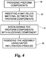
- FIGS. 5 and 6 show a CMC assembly 110 according to the invention.
- the CMC assembly 110 includes an airfoil 112 having airfoil connecting tabs 132, 134 that fit through an opening 156 of the endwall 114, and the endwall 114 rests over or upon seat portions 146, 148 of the airfoil 112.
- the FIG. 5 embodiment can have a mat filler material 120 provided between mating faces of the airfoil 112 and endwall 114, for example, between the cooperating surfaces 166 and 168 of the endwall 114 (underside of the endwall 114 as shown in FIGS. 4 and 5 ) and the seat portions 146 and 148 of the airfoil 112.
- the CMC assembly 110 has locking components 180, 182 that lock the airfoil 112 and endwall 114 together in a manner different from that of the locking components 18 of FIG. 1 .
- the locking components 180 can take the form of substantially rectangular shape locking members. As shown in FIG. 5 , the rectangular shape locking members 180 can be sized to fit into corresponding pre-machined or pre-formed substantially rectangular shape slots 186, 188 in the respective airfoil connecting tabs 132, 134.
- the slots 186, 188 can be positioned immediately above the endwall 114 in a state where the endwall 114 is assembled to the airfoil 112 in the FIG. 5 embodiment.
- the endwall 114 can be interlocked between the rectangular shaped locking members 180 and the seat portions 146 and 148 of the airfoil 112, which prevents withdrawal of the airfoil 112 from the endwall 114 in the direction from which airfoil 112 was inserted into the endwall 114, i.e. in the spanwise direction of the airfoil 112.
- the locking components 182 can take the form of locking pin members. Referring again to FIG. 5 , the locking pin members 182 can be sized to fit into corresponding through holes 192 in the rectangular shape locking members 180 and through holes 196 in the endwall 114. The locking pin members 182 can be substantially the same length as the combined thickness of the endwall 114 and the rectangular shape locking member 180. The locking pin members 182 can serve to maintain structural integrity of the CMC assembly 110 by for example preventing withdrawal of the rectangular shape locking members 180 from the slots 186, 188 during subsequent processing or at any time during the life of the components should for example the bond between an airfoil connecting tab 132, 134 and its corresponding rectangular shape locking member 180 fail.
- FIG. 7 is a flowchart depicting steps of a process for making a CMC assembly according to the invention.
- the airfoil 112 and endwall 114 preform components can be provided in their un-rigidized or partially-rigidized states (Step 200).
- the formed or machined airfoil connecting tabs 132, 134 can be pushed through the opening 156 in the endwall 114 so that the airfoil connecting tabs 132, 134 project through the opening 156 and the cooperating surfaces 166, 168 of the endwall 114 rest over or upon the seat portions 146, 148 of the airfoil 112, as shown for example in FIG. 6 .
- the mat filler material 120 can be placed between the mating faces of the airfoil 112 and endwall 114, for example between the cooperating surface 166 and the seat portion 146, either before or after the airfoil connecting tabs 132, 134 are pushed through the opening 156 (Step 202).
- the first locking components that is the rectangular shape locking members 180, can be inserted into the slots 186, 188 in the respective airfoil connecting tabs 132, 134, as shown for example in FIG. 6 , to lock the airfoil 112 to the endwall 114 (Step 204).
- the inward facing surfaces of the rectangular shape locking members 180 are substantially aligned with, that is flush with, the corresponding inward facing surfaces of the airfoil connecting tabs 132, 134.
- the second locking components that is, the locking pin members 182
- the assembled airfoil 112, endwall 114, locking components 180, 182, and mat filler material 120 can be rigidized using a vapor infiltration process (Step 208).
- any suitable process can be used for rigidizing the components, including for example chemical vapor infiltration, slurry/melt infiltration, polymer infiltration process, combined infiltration processes, to name just a few.
Landscapes
- Engineering & Computer Science (AREA)
- Mechanical Engineering (AREA)
- General Engineering & Computer Science (AREA)
- Chemical & Material Sciences (AREA)
- Materials Engineering (AREA)
- Composite Materials (AREA)
- Architecture (AREA)
- Turbine Rotor Nozzle Sealing (AREA)
Claims (12)
- Procédé de formation d'un ensemble aile portante de moteur à turbine à gaz, comprenant :la fourniture d'au moins deux composants de préforme de composite d'aile portante de moteur à turbine à gaz comprenant une aile portante (112) et une paroi d'extrémité (114),le verrouillage de l'aile portante et de la paroi d'extrémité avec un premier composant de verrouillage (180),le verrouillage du premier composant de verrouillage et de la paroi d'extrémité avec un second composant de verrouillage (182), dans lequel le verrouillage du second composant de verrouillage comprend l'insertion du second composant de verrouillage dans un orifice passant (192) dans le premier composant de verrouillage et un orifice passant (196) dans la paroi d'extrémité.
- Procédé selon la revendication 1, dans lequel des faces de correspondance de l'aile portante (112) et de la paroi d'extrémité (114) sont situées l'une en face de l'autre, comprenant en outre l'insertion d'un matériau de charge (120) entre les faces de correspondance de l'aile portante (112) et de la paroi d'extrémité (114).
- Procédé selon la revendication 1, dans lequel un ou plusieurs des composants de préforme composite d'aile portante sont fournis dans un état partiellement rigidifié.
- Procédé selon la revendication 1, dans lequel les composants de préforme de composite d'aile portante comprennent une fibre tissée.
- Procédé selon la revendication 1, dans lequel l'aile portante (112) inclut au moins une patte de raccordement d'aile portante (132, 134) et une partie de siège (146, 148), la paroi d'extrémité (114) définit une ouverture (156) sensiblement dimensionnée afin de recevoir à travers elle la au moins une patte de raccordement d'aile portante, dans lequel la fourniture comprend l'insertion de la au moins une patte de raccordement d'aile portante de l'aile portante dans l'ouverture de la paroi d'extrémité, de sorte que la paroi d'extrémité s'appuie sur la partie de siège.
- Procédé selon la revendication 4, dans lequel :(i) le verrouillage comprend l'insertion du premier composant de verrouillage (180) dans un orifice passant (186, 188) dans la au moins une patte de raccordement d'aile portante (132, 134) de sorte qu'une partie arrière du premier composant de verrouillage s'appuie sur une partie de la paroi d'extrémité (114) afin d'interverrouiller la paroi d'extrémité entre le premier composant de verrouillage et la partie de siège (146, 148) ; ou(ii) la partie de siège (146, 148) fournit la face de correspondance de l'aile portante et la partie de la paroi d'extrémité sur la partie de siège fournit la face de correspondance de la paroi d'extrémité et l'insertion du matériau de charge (120) comprend l'insertion du matériau de charge entre la face de correspondance de l'aile portante et la face de correspondance de la paroi d'extrémité.
- Procédé selon la revendication 2, comprenant en outre la rigidification de l'ensemble de composants de préforme composite d'aile portante, du premier composant de verrouillage (180), du second composant de verrouillage (182) et du matériau de charge (120), éventuellement dans lequel la rigidification comprend l'utilisation d'infiltration de vapeur.
- Procédé selon la revendication 1, comprenant en outre la rigidification de l'ensemble de composants de préforme composite d'aile portante, du premier composant de verrouillage (180), du second composant de verrouillage (182), éventuellement dans lequel la rigidification comprend l'utilisation d'infiltration de vapeur.
- Ensemble aile portante de moteur à turbine à gaz formé par le procédé selon l'une quelconque des revendications 1 ou 2.
- Ensemble aile portante de moteur à turbine à gaz, comprenant :une aile portante composite (112) incluant un côté pression et un côté aspiration présentant un creux entre eux, et une patte de raccordement d'aile portante s'étendant depuis le côté pression (134) dans le sens de l'envergure et une patte de raccordement d'aile portante (132) s'étendant depuis le côté aspiration dans le sens de l'envergure ; etune paroi d'extrémité composite (114) transversale à l'aile portante composite, etdes moyens de verrouillage côté pression qui empêchent ou inhibent le mouvement latéral relatif entre la paroi d'extrémité composite et la patte de raccordement d'aile portante côté pression, les moyens de verrouillage côté pression comprenant un premier composant de verrouillage côté pression (180) configuré afin d'interverrouiller la patte de raccordement d'aile portante côté pression et la paroi d'extrémité composite, et un second composant de verrouillage côté pression (182) configuré afin d'être inséré dans un orifice passant (192) dans le premier composant de verrouillage côté pression et un orifice passant (196) dans la paroi d'extrémité afin d'interverrouiller le premier composant de verrouillage côté pression et la paroi d'extrémité, etdes moyens de verrouillage côté aspiration qui empêchent ou inhibent le mouvement latéral relatif entre la paroi d'extrémité composite et la patte de raccordement d'aile portante côté pression, les moyens de verrouillage côté aspiration comprenant un premier composant de verrouillage côté aspiration (180) configuré afin d'interverrouiller la patte de raccordement d'aile portante côté aspiration et la paroi d'extrémité composite, et un second composant de verrouillage côté aspiration (182) configuré afin d'être inséré dans un orifice passant (192) dans le premier composant de verrouillage côté aspiration et un orifice passant (196) dans la paroi d'extrémité afin d'interverrouiller le premier composant de verrouillage côté aspiration et la paroi d'extrémité.
- Ensemble aile portante de moteur à turbine à gaz selon la revendication 10, dans lequel l'aile portante composite (112) définit une paire de parties de sièges (146, 148) à des extrémités opposées des pattes de raccordement d'aile portante (132, 134) s'étendant depuis le côté pression et le côté aspiration de l'aile portante composite, et
la paroi d'extrémité composite (114) présentant une partie de plate-forme qui définit des surfaces de coopération permettant de s'appuyer dessus ou permettant de s'appuyer sur lesdites parties de sièges définies par l'aile portante composite. - Ensemble aile portante de moteur à turbine à gaz selon la revendication 10, comprenant une structure composite intégrale.
Applications Claiming Priority (2)
| Application Number | Priority Date | Filing Date | Title |
|---|---|---|---|
| US201361774987P | 2013-03-08 | 2013-03-08 | |
| PCT/US2013/077469 WO2014137457A1 (fr) | 2013-03-08 | 2013-12-23 | Procédé de formation d'un ensemble aile portante composite de moteur à turbine à gaz et ensemble aile portante correspondante |
Publications (2)
| Publication Number | Publication Date |
|---|---|
| EP2964887A1 EP2964887A1 (fr) | 2016-01-13 |
| EP2964887B1 true EP2964887B1 (fr) | 2019-06-26 |
Family
ID=49998691
Family Applications (1)
| Application Number | Title | Priority Date | Filing Date |
|---|---|---|---|
| EP13822051.2A Not-in-force EP2964887B1 (fr) | 2013-03-08 | 2013-12-23 | Procédé de formation d'un ensemble aile portante composite de moteur à turbine à gaz et ensemble aile portante correspondante |
Country Status (4)
| Country | Link |
|---|---|
| US (2) | US10174619B2 (fr) |
| EP (1) | EP2964887B1 (fr) |
| CA (1) | CA2903730A1 (fr) |
| WO (1) | WO2014137457A1 (fr) |
Families Citing this family (32)
| Publication number | Priority date | Publication date | Assignee | Title |
|---|---|---|---|---|
| WO2016043743A1 (fr) * | 2014-09-18 | 2016-03-24 | Siemens Aktiengesellschaft | Materiau composite a nanofils |
| US10329950B2 (en) * | 2015-03-23 | 2019-06-25 | Rolls-Royce North American Technologies Inc. | Nozzle guide vane with composite heat shield |
| EP3236009A1 (fr) * | 2016-04-21 | 2017-10-25 | Siemens Aktiengesellschaft | Aube directrice comprenant un tuyau de raccordement |
| US10633988B2 (en) * | 2016-07-06 | 2020-04-28 | United Technologies Corporation | Ring stator |
| FR3059706B1 (fr) * | 2016-12-02 | 2020-10-23 | Safran Aircraft Engines | Redresseur de flux pour turbomachine a fixation amovible |
| US10767502B2 (en) | 2016-12-23 | 2020-09-08 | Rolls-Royce Corporation | Composite turbine vane with three-dimensional fiber reinforcements |
| US10393381B2 (en) | 2017-01-27 | 2019-08-27 | General Electric Company | Unitary flow path structure |
| US10253643B2 (en) | 2017-02-07 | 2019-04-09 | General Electric Company | Airfoil fluid curtain to mitigate or prevent flow path leakage |
| US10253641B2 (en) | 2017-02-23 | 2019-04-09 | General Electric Company | Methods and assemblies for attaching airfoils within a flow path |
| US10385709B2 (en) | 2017-02-23 | 2019-08-20 | General Electric Company | Methods and features for positioning a flow path assembly within a gas turbine engine |
| US10247019B2 (en) | 2017-02-23 | 2019-04-02 | General Electric Company | Methods and features for positioning a flow path inner boundary within a flow path assembly |
| US10378373B2 (en) * | 2017-02-23 | 2019-08-13 | General Electric Company | Flow path assembly with airfoils inserted through flow path boundary |
| US10533456B2 (en) | 2017-05-26 | 2020-01-14 | United Technologies Corporation | Stator assembly with contoured retention clip for gas turbine engine |
| US10385731B2 (en) | 2017-06-12 | 2019-08-20 | General Electric Company | CTE matching hanger support for CMC structures |
| US10746035B2 (en) | 2017-08-30 | 2020-08-18 | General Electric Company | Flow path assemblies for gas turbine engines and assembly methods therefore |
| FR3071538B1 (fr) * | 2017-09-27 | 2020-09-04 | Safran Aircraft Engines | Aube de rotor pour une turbomachine |
| US11802486B2 (en) * | 2017-11-13 | 2023-10-31 | General Electric Company | CMC component and fabrication using mechanical joints |
| US11466580B2 (en) * | 2018-05-02 | 2022-10-11 | General Electric Company | CMC nozzle with interlocking mechanical joint and fabrication |
| US10934870B2 (en) | 2018-09-17 | 2021-03-02 | Rolls Royce Plc | Turbine vane assembly with reinforced end wall joints |
| US10859268B2 (en) | 2018-10-03 | 2020-12-08 | Rolls-Royce Plc | Ceramic matrix composite turbine vanes and vane ring assemblies |
| KR102116504B1 (ko) * | 2018-12-03 | 2020-05-28 | 두산중공업 주식회사 | 베인, 베인 제조방법 및 가스터빈 |
| US11193381B2 (en) | 2019-05-17 | 2021-12-07 | Rolls-Royce Plc | Turbine vane assembly having ceramic matrix composite components with sliding support |
| US11162377B2 (en) | 2019-05-31 | 2021-11-02 | Rolls-Royce High Temperature Composites Inc. | Ceramic matrix composite turbine vane and method for making |
| US10890076B1 (en) | 2019-06-28 | 2021-01-12 | Rolls-Royce Plc | Turbine vane assembly having ceramic matrix composite components with expandable spar support |
| US11162372B2 (en) | 2019-12-04 | 2021-11-02 | Rolls-Royce Plc | Turbine vane doublet with ceramic matrix composite material construction |
| CN110985134B (zh) * | 2019-12-13 | 2022-06-21 | 西安鑫垚陶瓷复合材料有限公司 | 航空发动机陶瓷基复合材料固定导向器叶片结构及其成型 |
| CN111102017B (zh) * | 2019-12-13 | 2022-07-12 | 西安鑫垚陶瓷复合材料有限公司 | 航空发动机陶瓷基复合材料固定导向器叶片结构及其成型 |
| US11415013B1 (en) * | 2021-09-30 | 2022-08-16 | Rolls-Royce Plc | Ceramic matrix composite vane with integrated platform joint |
| US11560799B1 (en) | 2021-10-22 | 2023-01-24 | Rolls-Royce High Temperature Composites Inc. | Ceramic matrix composite vane assembly with shaped load transfer features |
| US12241374B2 (en) | 2023-05-10 | 2025-03-04 | Rolls-Royce Corporation | Ceramic matrix composite endwall sealing around vane airfoil of gas turbine engine |
| FR3159110A1 (fr) * | 2024-02-13 | 2025-08-15 | Safran Ceramics | Procédé de fabrication d'une aube en matériau composite |
| US12503949B1 (en) * | 2024-11-21 | 2025-12-23 | Rtx Corporation | Gapped attachment for ceramic matrix composite vane and method |
Family Cites Families (35)
| Publication number | Priority date | Publication date | Assignee | Title |
|---|---|---|---|---|
| GB695724A (en) * | 1950-08-01 | 1953-08-19 | Rolls Royce | Improvements in or relating to structural elements for axial-flow turbo-machines such as compressors or turbines of gas-turbine engines |
| US3053505A (en) * | 1958-06-11 | 1962-09-11 | Gen Motors Corp | Pinned blade shrouding |
| FR1542561A (fr) * | 1967-07-07 | Snecma | Dispositif de fixation d'aubes pour turbomachines | |
| US5203488A (en) | 1990-07-12 | 1993-04-20 | Lanxide Technology Company, Lp | Method for joining ceramic composite bodies and articles formed thereby |
| US5350545A (en) * | 1991-05-01 | 1994-09-27 | General Atomics | Method of fabrication of composites |
| FR2697285B1 (fr) * | 1992-10-28 | 1994-11-25 | Snecma | Système de verrouillage d'extrémités d'aubes. |
| US5272869A (en) * | 1992-12-10 | 1993-12-28 | General Electric Company | Turbine frame |
| US5765993A (en) * | 1996-09-27 | 1998-06-16 | Chromalloy Gas Turbine Corporation | Replacement vane assembly for fan exit guide |
| US6045310A (en) | 1997-10-06 | 2000-04-04 | United Technologies Corporation | Composite fastener for use in high temperature environments |
| US6409472B1 (en) * | 1999-08-09 | 2002-06-25 | United Technologies Corporation | Stator assembly for a rotary machine and clip member for a stator assembly |
| DE60026687T2 (de) * | 2000-12-06 | 2006-11-09 | Techspace Aero S.A. | Statorstufe eines Verdichters |
| US6648597B1 (en) | 2002-05-31 | 2003-11-18 | Siemens Westinghouse Power Corporation | Ceramic matrix composite turbine vane |
| US9068464B2 (en) * | 2002-09-17 | 2015-06-30 | Siemens Energy, Inc. | Method of joining ceramic parts and articles so formed |
| US6884026B2 (en) * | 2002-09-30 | 2005-04-26 | General Electric Company | Turbine engine shroud assembly including axially floating shroud segment |
| US7080971B2 (en) * | 2003-03-12 | 2006-07-25 | Florida Turbine Technologies, Inc. | Cooled turbine spar shell blade construction |
| US7044709B2 (en) | 2004-01-15 | 2006-05-16 | General Electric Company | Methods and apparatus for coupling ceramic matrix composite turbine components |
| US7393182B2 (en) * | 2005-05-05 | 2008-07-01 | Florida Turbine Technologies, Inc. | Composite tip shroud ring |
| US7754126B2 (en) | 2005-06-17 | 2010-07-13 | General Electric Company | Interlaminar tensile reinforcement of SiC/SiC CMC's using fugitive fibers |
| US7549840B2 (en) * | 2005-06-17 | 2009-06-23 | General Electric Company | Through thickness reinforcement of SiC/SiC CMC's through in-situ matrix plugs manufactured using fugitive fibers |
| US7329087B2 (en) | 2005-09-19 | 2008-02-12 | General Electric Company | Seal-less CMC vane to platform interfaces |
| US7950234B2 (en) | 2006-10-13 | 2011-05-31 | Siemens Energy, Inc. | Ceramic matrix composite turbine engine components with unitary stiffening frame |
| US7799405B1 (en) * | 2006-12-01 | 2010-09-21 | Siemens Energy, Inc. | Three dimensional reinforced CMC articles by interlocking two dimensional structures |
| US7832972B2 (en) | 2008-03-05 | 2010-11-16 | United Technologies Corporation | Internal pocket fastener system for ceramic matrix composites |
| US8251652B2 (en) * | 2008-09-18 | 2012-08-28 | Siemens Energy, Inc. | Gas turbine vane platform element |
| US9062562B2 (en) * | 2008-11-28 | 2015-06-23 | Herakles | Composite material turbomachine engine blade or vane, compressor stator segment or turbine nozzle segment incorporating such vanes and method for manufacturing same |
| US8127798B2 (en) * | 2008-12-23 | 2012-03-06 | Capital Hardware Supply Co., Inc. | Turning vane for air duct |
| US8714932B2 (en) | 2008-12-31 | 2014-05-06 | General Electric Company | Ceramic matrix composite blade having integral platform structures and methods of fabrication |
| US7988395B2 (en) | 2009-01-23 | 2011-08-02 | Steffier Wayne S | Mechanical fastener system for high-temperature structural assemblies |
| JP5311126B2 (ja) * | 2009-03-26 | 2013-10-09 | 株式会社Ihi | Cmcタービン静翼 |
| JP5321186B2 (ja) * | 2009-03-26 | 2013-10-23 | 株式会社Ihi | Cmcタービン静翼 |
| US9033673B2 (en) * | 2010-06-28 | 2015-05-19 | Herakles | Turbomachine blade or vane having complementary asymmetrical geometry |
| FR2975123B1 (fr) * | 2011-05-13 | 2013-06-14 | Snecma Propulsion Solide | Rotor de turbomachine comprenant des aubes en materiau composite avec talon rapporte |
| US8834125B2 (en) * | 2011-05-26 | 2014-09-16 | United Technologies Corporation | Hybrid rotor disk assembly with a ceramic matrix composite airfoil for a gas turbine engine |
| US8851853B2 (en) * | 2011-05-26 | 2014-10-07 | United Technologies Corporation | Hybrid rotor disk assembly for a gas turbine engine |
| US9163519B2 (en) * | 2011-07-28 | 2015-10-20 | General Electric Company | Cap for ceramic blade tip shroud |
-
2013
- 2013-12-23 WO PCT/US2013/077469 patent/WO2014137457A1/fr not_active Ceased
- 2013-12-23 EP EP13822051.2A patent/EP2964887B1/fr not_active Not-in-force
- 2013-12-23 CA CA2903730A patent/CA2903730A1/fr not_active Abandoned
- 2013-12-23 US US14/138,725 patent/US10174619B2/en active Active
-
2018
- 2018-11-27 US US16/201,301 patent/US11053801B2/en active Active
Non-Patent Citations (1)
| Title |
|---|
| None * |
Also Published As
| Publication number | Publication date |
|---|---|
| US20150003989A1 (en) | 2015-01-01 |
| US11053801B2 (en) | 2021-07-06 |
| WO2014137457A1 (fr) | 2014-09-12 |
| US20200024955A1 (en) | 2020-01-23 |
| EP2964887A1 (fr) | 2016-01-13 |
| CA2903730A1 (fr) | 2014-09-12 |
| US10174619B2 (en) | 2019-01-08 |
Similar Documents
| Publication | Publication Date | Title |
|---|---|---|
| EP2964887B1 (fr) | Procédé de formation d'un ensemble aile portante composite de moteur à turbine à gaz et ensemble aile portante correspondante | |
| CN106103904B (zh) | 涡轮发动机的定子扇区,及其制造方法 | |
| US20230003133A1 (en) | Blade made of composite material with variable-density attached leading edge | |
| US7258530B2 (en) | CMC component and method of fabrication | |
| US11111798B2 (en) | Turbomachine blade and method for the manufacture of same | |
| CN109424371B (zh) | 用于燃气涡轮发动机的流径组件及其组装方法 | |
| CN104812950B (zh) | 用于制造复合材料的涡轮发动机叶片根部的方法以及通过这种方法获得的叶片根部 | |
| US8616801B2 (en) | Gusset with fibers oriented to strengthen a CMC wall intersection anisotropically | |
| US7968144B2 (en) | System for applying a continuous surface layer on porous substructures of turbine airfoils | |
| US20160146028A1 (en) | High strength joints in ceramic matrix composite preforms | |
| EP2837796A1 (fr) | Procédé de fabrication d'aubes de turbine accouplées et aubes de turbine accouplées | |
| CA2430050A1 (fr) | Aube de turbine en composite a matrice ceramique | |
| JP6174839B2 (ja) | セラミックス基複合部材およびその製造方法 | |
| CN107075958B (zh) | 由机械锚固元件组装的两个零件的组件,由复合材料制成的一个零件 | |
| US10174624B1 (en) | Composite blade root lay-up | |
| CN103415388A (zh) | 包括固定装置的复合材料零件 | |
| US8220131B2 (en) | Assembly of aircraft components | |
| JP6616402B2 (ja) | ガスタービンエンジン用の千鳥状取付フランジを具備する複合材料製案内翼 | |
| WO2019137765A1 (fr) | Corps façonné en cmc et son procédé de fabrication | |
| US9617857B2 (en) | Gas turbine engine component |
Legal Events
| Date | Code | Title | Description |
|---|---|---|---|
| PUAI | Public reference made under article 153(3) epc to a published international application that has entered the european phase |
Free format text: ORIGINAL CODE: 0009012 |
|
| 17P | Request for examination filed |
Effective date: 20150916 |
|
| AK | Designated contracting states |
Kind code of ref document: A1 Designated state(s): AL AT BE BG CH CY CZ DE DK EE ES FI FR GB GR HR HU IE IS IT LI LT LU LV MC MK MT NL NO PL PT RO RS SE SI SK SM TR |
|
| AX | Request for extension of the european patent |
Extension state: BA ME |
|
| RIN1 | Information on inventor provided before grant (corrected) |
Inventor name: SHINAVSKI, ROBERT J. Inventor name: THOMAS, DAVID J. Inventor name: USKERT, RICHARD C. Inventor name: STEFFIER, WAYNE S. Inventor name: CHAMBERLAIN, ADAM L. |
|
| DAX | Request for extension of the european patent (deleted) | ||
| STAA | Information on the status of an ep patent application or granted ep patent |
Free format text: STATUS: EXAMINATION IS IN PROGRESS |
|
| 17Q | First examination report despatched |
Effective date: 20180607 |
|
| GRAP | Despatch of communication of intention to grant a patent |
Free format text: ORIGINAL CODE: EPIDOSNIGR1 |
|
| STAA | Information on the status of an ep patent application or granted ep patent |
Free format text: STATUS: GRANT OF PATENT IS INTENDED |
|
| INTG | Intention to grant announced |
Effective date: 20190122 |
|
| GRAS | Grant fee paid |
Free format text: ORIGINAL CODE: EPIDOSNIGR3 |
|
| GRAA | (expected) grant |
Free format text: ORIGINAL CODE: 0009210 |
|
| STAA | Information on the status of an ep patent application or granted ep patent |
Free format text: STATUS: THE PATENT HAS BEEN GRANTED |
|
| AK | Designated contracting states |
Kind code of ref document: B1 Designated state(s): AL AT BE BG CH CY CZ DE DK EE ES FI FR GB GR HR HU IE IS IT LI LT LU LV MC MK MT NL NO PL PT RO RS SE SI SK SM TR |
|
| REG | Reference to a national code |
Ref country code: GB Ref legal event code: FG4D |
|
| REG | Reference to a national code |
Ref country code: CH Ref legal event code: EP |
|
| REG | Reference to a national code |
Ref country code: DE Ref legal event code: R096 Ref document number: 602013057193 Country of ref document: DE |
|
| REG | Reference to a national code |
Ref country code: AT Ref legal event code: REF Ref document number: 1148513 Country of ref document: AT Kind code of ref document: T Effective date: 20190715 |
|
| REG | Reference to a national code |
Ref country code: IE Ref legal event code: FG4D |
|
| REG | Reference to a national code |
Ref country code: NL Ref legal event code: MP Effective date: 20190626 |
|
| PG25 | Lapsed in a contracting state [announced via postgrant information from national office to epo] |
Ref country code: HR Free format text: LAPSE BECAUSE OF FAILURE TO SUBMIT A TRANSLATION OF THE DESCRIPTION OR TO PAY THE FEE WITHIN THE PRESCRIBED TIME-LIMIT Effective date: 20190626 Ref country code: NO Free format text: LAPSE BECAUSE OF FAILURE TO SUBMIT A TRANSLATION OF THE DESCRIPTION OR TO PAY THE FEE WITHIN THE PRESCRIBED TIME-LIMIT Effective date: 20190926 Ref country code: SE Free format text: LAPSE BECAUSE OF FAILURE TO SUBMIT A TRANSLATION OF THE DESCRIPTION OR TO PAY THE FEE WITHIN THE PRESCRIBED TIME-LIMIT Effective date: 20190626 Ref country code: FI Free format text: LAPSE BECAUSE OF FAILURE TO SUBMIT A TRANSLATION OF THE DESCRIPTION OR TO PAY THE FEE WITHIN THE PRESCRIBED TIME-LIMIT Effective date: 20190626 Ref country code: AL Free format text: LAPSE BECAUSE OF FAILURE TO SUBMIT A TRANSLATION OF THE DESCRIPTION OR TO PAY THE FEE WITHIN THE PRESCRIBED TIME-LIMIT Effective date: 20190626 Ref country code: LT Free format text: LAPSE BECAUSE OF FAILURE TO SUBMIT A TRANSLATION OF THE DESCRIPTION OR TO PAY THE FEE WITHIN THE PRESCRIBED TIME-LIMIT Effective date: 20190626 |
|
| REG | Reference to a national code |
Ref country code: LT Ref legal event code: MG4D |
|
| PG25 | Lapsed in a contracting state [announced via postgrant information from national office to epo] |
Ref country code: BG Free format text: LAPSE BECAUSE OF FAILURE TO SUBMIT A TRANSLATION OF THE DESCRIPTION OR TO PAY THE FEE WITHIN THE PRESCRIBED TIME-LIMIT Effective date: 20190926 Ref country code: RS Free format text: LAPSE BECAUSE OF FAILURE TO SUBMIT A TRANSLATION OF THE DESCRIPTION OR TO PAY THE FEE WITHIN THE PRESCRIBED TIME-LIMIT Effective date: 20190626 Ref country code: GR Free format text: LAPSE BECAUSE OF FAILURE TO SUBMIT A TRANSLATION OF THE DESCRIPTION OR TO PAY THE FEE WITHIN THE PRESCRIBED TIME-LIMIT Effective date: 20190927 Ref country code: LV Free format text: LAPSE BECAUSE OF FAILURE TO SUBMIT A TRANSLATION OF THE DESCRIPTION OR TO PAY THE FEE WITHIN THE PRESCRIBED TIME-LIMIT Effective date: 20190626 |
|
| REG | Reference to a national code |
Ref country code: AT Ref legal event code: MK05 Ref document number: 1148513 Country of ref document: AT Kind code of ref document: T Effective date: 20190626 |
|
| PG25 | Lapsed in a contracting state [announced via postgrant information from national office to epo] |
Ref country code: SK Free format text: LAPSE BECAUSE OF FAILURE TO SUBMIT A TRANSLATION OF THE DESCRIPTION OR TO PAY THE FEE WITHIN THE PRESCRIBED TIME-LIMIT Effective date: 20190626 Ref country code: CZ Free format text: LAPSE BECAUSE OF FAILURE TO SUBMIT A TRANSLATION OF THE DESCRIPTION OR TO PAY THE FEE WITHIN THE PRESCRIBED TIME-LIMIT Effective date: 20190626 Ref country code: NL Free format text: LAPSE BECAUSE OF FAILURE TO SUBMIT A TRANSLATION OF THE DESCRIPTION OR TO PAY THE FEE WITHIN THE PRESCRIBED TIME-LIMIT Effective date: 20190626 Ref country code: RO Free format text: LAPSE BECAUSE OF FAILURE TO SUBMIT A TRANSLATION OF THE DESCRIPTION OR TO PAY THE FEE WITHIN THE PRESCRIBED TIME-LIMIT Effective date: 20190626 Ref country code: EE Free format text: LAPSE BECAUSE OF FAILURE TO SUBMIT A TRANSLATION OF THE DESCRIPTION OR TO PAY THE FEE WITHIN THE PRESCRIBED TIME-LIMIT Effective date: 20190626 Ref country code: AT Free format text: LAPSE BECAUSE OF FAILURE TO SUBMIT A TRANSLATION OF THE DESCRIPTION OR TO PAY THE FEE WITHIN THE PRESCRIBED TIME-LIMIT Effective date: 20190626 Ref country code: PT Free format text: LAPSE BECAUSE OF FAILURE TO SUBMIT A TRANSLATION OF THE DESCRIPTION OR TO PAY THE FEE WITHIN THE PRESCRIBED TIME-LIMIT Effective date: 20191028 |
|
| PG25 | Lapsed in a contracting state [announced via postgrant information from national office to epo] |
Ref country code: SM Free format text: LAPSE BECAUSE OF FAILURE TO SUBMIT A TRANSLATION OF THE DESCRIPTION OR TO PAY THE FEE WITHIN THE PRESCRIBED TIME-LIMIT Effective date: 20190626 Ref country code: IS Free format text: LAPSE BECAUSE OF FAILURE TO SUBMIT A TRANSLATION OF THE DESCRIPTION OR TO PAY THE FEE WITHIN THE PRESCRIBED TIME-LIMIT Effective date: 20191026 Ref country code: IT Free format text: LAPSE BECAUSE OF FAILURE TO SUBMIT A TRANSLATION OF THE DESCRIPTION OR TO PAY THE FEE WITHIN THE PRESCRIBED TIME-LIMIT Effective date: 20190626 Ref country code: ES Free format text: LAPSE BECAUSE OF FAILURE TO SUBMIT A TRANSLATION OF THE DESCRIPTION OR TO PAY THE FEE WITHIN THE PRESCRIBED TIME-LIMIT Effective date: 20190626 |
|
| PGFP | Annual fee paid to national office [announced via postgrant information from national office to epo] |
Ref country code: FR Payment date: 20191226 Year of fee payment: 7 |
|
| PG25 | Lapsed in a contracting state [announced via postgrant information from national office to epo] |
Ref country code: TR Free format text: LAPSE BECAUSE OF FAILURE TO SUBMIT A TRANSLATION OF THE DESCRIPTION OR TO PAY THE FEE WITHIN THE PRESCRIBED TIME-LIMIT Effective date: 20190626 |
|
| PG25 | Lapsed in a contracting state [announced via postgrant information from national office to epo] |
Ref country code: PL Free format text: LAPSE BECAUSE OF FAILURE TO SUBMIT A TRANSLATION OF THE DESCRIPTION OR TO PAY THE FEE WITHIN THE PRESCRIBED TIME-LIMIT Effective date: 20190626 Ref country code: DK Free format text: LAPSE BECAUSE OF FAILURE TO SUBMIT A TRANSLATION OF THE DESCRIPTION OR TO PAY THE FEE WITHIN THE PRESCRIBED TIME-LIMIT Effective date: 20190626 |
|
| PGFP | Annual fee paid to national office [announced via postgrant information from national office to epo] |
Ref country code: DE Payment date: 20191231 Year of fee payment: 7 |
|
| PG25 | Lapsed in a contracting state [announced via postgrant information from national office to epo] |
Ref country code: IS Free format text: LAPSE BECAUSE OF FAILURE TO SUBMIT A TRANSLATION OF THE DESCRIPTION OR TO PAY THE FEE WITHIN THE PRESCRIBED TIME-LIMIT Effective date: 20200224 |
|
| REG | Reference to a national code |
Ref country code: DE Ref legal event code: R097 Ref document number: 602013057193 Country of ref document: DE |
|
| PLBE | No opposition filed within time limit |
Free format text: ORIGINAL CODE: 0009261 |
|
| STAA | Information on the status of an ep patent application or granted ep patent |
Free format text: STATUS: NO OPPOSITION FILED WITHIN TIME LIMIT |
|
| PG2D | Information on lapse in contracting state deleted |
Ref country code: IS |
|
| REG | Reference to a national code |
Ref country code: CH Ref legal event code: PL |
|
| 26N | No opposition filed |
Effective date: 20200603 |
|
| REG | Reference to a national code |
Ref country code: BE Ref legal event code: MM Effective date: 20191231 |
|
| PG25 | Lapsed in a contracting state [announced via postgrant information from national office to epo] |
Ref country code: SI Free format text: LAPSE BECAUSE OF FAILURE TO SUBMIT A TRANSLATION OF THE DESCRIPTION OR TO PAY THE FEE WITHIN THE PRESCRIBED TIME-LIMIT Effective date: 20190626 Ref country code: MC Free format text: LAPSE BECAUSE OF FAILURE TO SUBMIT A TRANSLATION OF THE DESCRIPTION OR TO PAY THE FEE WITHIN THE PRESCRIBED TIME-LIMIT Effective date: 20190626 |
|
| GBPC | Gb: european patent ceased through non-payment of renewal fee |
Effective date: 20191223 |
|
| PG25 | Lapsed in a contracting state [announced via postgrant information from national office to epo] |
Ref country code: LU Free format text: LAPSE BECAUSE OF NON-PAYMENT OF DUE FEES Effective date: 20191223 Ref country code: IE Free format text: LAPSE BECAUSE OF NON-PAYMENT OF DUE FEES Effective date: 20191223 Ref country code: GB Free format text: LAPSE BECAUSE OF NON-PAYMENT OF DUE FEES Effective date: 20191223 |
|
| PG25 | Lapsed in a contracting state [announced via postgrant information from national office to epo] |
Ref country code: LI Free format text: LAPSE BECAUSE OF NON-PAYMENT OF DUE FEES Effective date: 20191231 Ref country code: CH Free format text: LAPSE BECAUSE OF NON-PAYMENT OF DUE FEES Effective date: 20191231 Ref country code: BE Free format text: LAPSE BECAUSE OF NON-PAYMENT OF DUE FEES Effective date: 20191231 |
|
| PG25 | Lapsed in a contracting state [announced via postgrant information from national office to epo] |
Ref country code: CY Free format text: LAPSE BECAUSE OF FAILURE TO SUBMIT A TRANSLATION OF THE DESCRIPTION OR TO PAY THE FEE WITHIN THE PRESCRIBED TIME-LIMIT Effective date: 20190626 |
|
| REG | Reference to a national code |
Ref country code: DE Ref legal event code: R119 Ref document number: 602013057193 Country of ref document: DE |
|
| PG25 | Lapsed in a contracting state [announced via postgrant information from national office to epo] |
Ref country code: MT Free format text: LAPSE BECAUSE OF FAILURE TO SUBMIT A TRANSLATION OF THE DESCRIPTION OR TO PAY THE FEE WITHIN THE PRESCRIBED TIME-LIMIT Effective date: 20190626 Ref country code: HU Free format text: LAPSE BECAUSE OF FAILURE TO SUBMIT A TRANSLATION OF THE DESCRIPTION OR TO PAY THE FEE WITHIN THE PRESCRIBED TIME-LIMIT; INVALID AB INITIO Effective date: 20131223 |
|
| PG25 | Lapsed in a contracting state [announced via postgrant information from national office to epo] |
Ref country code: FR Free format text: LAPSE BECAUSE OF NON-PAYMENT OF DUE FEES Effective date: 20201231 |
|
| PG25 | Lapsed in a contracting state [announced via postgrant information from national office to epo] |
Ref country code: DE Free format text: LAPSE BECAUSE OF NON-PAYMENT OF DUE FEES Effective date: 20210701 |
|
| PG25 | Lapsed in a contracting state [announced via postgrant information from national office to epo] |
Ref country code: MK Free format text: LAPSE BECAUSE OF FAILURE TO SUBMIT A TRANSLATION OF THE DESCRIPTION OR TO PAY THE FEE WITHIN THE PRESCRIBED TIME-LIMIT Effective date: 20190626 |
|
| P01 | Opt-out of the competence of the unified patent court (upc) registered |
Effective date: 20230528 |