EP2964904B1 - Moteur à turbine à gaz - Google Patents
Moteur à turbine à gaz Download PDFInfo
- Publication number
- EP2964904B1 EP2964904B1 EP13808356.3A EP13808356A EP2964904B1 EP 2964904 B1 EP2964904 B1 EP 2964904B1 EP 13808356 A EP13808356 A EP 13808356A EP 2964904 B1 EP2964904 B1 EP 2964904B1
- Authority
- EP
- European Patent Office
- Prior art keywords
- stage
- rotor
- rotating
- gas turbine
- turbine engine
- Prior art date
- Legal status (The legal status is an assumption and is not a legal conclusion. Google has not performed a legal analysis and makes no representation as to the accuracy of the status listed.)
- Active
Links
Images

Classifications
-
- H—ELECTRICITY
- H02—GENERATION; CONVERSION OR DISTRIBUTION OF ELECTRIC POWER
- H02K—DYNAMO-ELECTRIC MACHINES
- H02K7/00—Arrangements for handling mechanical energy structurally associated with dynamo-electric machines, e.g. structural association with mechanical driving motors or auxiliary dynamo-electric machines
- H02K7/18—Structural association of electric generators with mechanical driving motors, e.g. with turbines
- H02K7/1807—Rotary generators
- H02K7/1823—Rotary generators structurally associated with turbines or similar engines
-
- F—MECHANICAL ENGINEERING; LIGHTING; HEATING; WEAPONS; BLASTING
- F01—MACHINES OR ENGINES IN GENERAL; ENGINE PLANTS IN GENERAL; STEAM ENGINES
- F01D—NON-POSITIVE DISPLACEMENT MACHINES OR ENGINES, e.g. STEAM TURBINES
- F01D15/00—Adaptations of machines or engines for special use; Combinations of engines with devices driven thereby
- F01D15/10—Adaptations for driving, or combinations with, electric generators
-
- F—MECHANICAL ENGINEERING; LIGHTING; HEATING; WEAPONS; BLASTING
- F02—COMBUSTION ENGINES; HOT-GAS OR COMBUSTION-PRODUCT ENGINE PLANTS
- F02K—JET-PROPULSION PLANTS
- F02K3/00—Plants including a gas turbine driving a compressor or a ducted fan
- F02K3/02—Plants including a gas turbine driving a compressor or a ducted fan in which part of the working fluid by-passes the turbine and combustion chamber
-
- F—MECHANICAL ENGINEERING; LIGHTING; HEATING; WEAPONS; BLASTING
- F05—INDEXING SCHEMES RELATING TO ENGINES OR PUMPS IN VARIOUS SUBCLASSES OF CLASSES F01-F04
- F05D—INDEXING SCHEME FOR ASPECTS RELATING TO NON-POSITIVE-DISPLACEMENT MACHINES OR ENGINES, GAS-TURBINES OR JET-PROPULSION PLANTS
- F05D2220/00—Application
- F05D2220/70—Application in combination with
- F05D2220/76—Application in combination with an electrical generator
Definitions
- the present disclosure relates to gas turbine engines, and more particularly, to gas turbine engines equipped with electrical machines for generating electrical power.
- One embodiment of the present disclosure is a unique gas turbine engine having an electrical machine for generating electrical power.
- Other embodiments include other unique gas turbine engines having electrical machines for generating electrical power.
- gas turbine engine 10 is an aircraft propulsion power plant.
- gas turbine engine 10 may be a land-based or marine engine.
- gas turbine engine 10 is a multi-spool turbofan engine.
- gas turbine engine 10 may take other forms, and may be, for example, a turboshaft engine, a turbojet engine, a turboprop engine, or a combined cycle engine having a single spool or multiple spools.
- gas turbine engine 10 includes a fan system 12, a bypass duct 14, a compressor 16, a diffuser 18, a combustor 20, a turbine 22, an electrical machine 24, a discharge duct 26 and a nozzle system 28.
- Bypass duct 14 and compressor 16 are in fluid communication with fan system 12.
- Diffuser 18 is in fluid communication with compressor 16.
- Combustor 20 is fluidly disposed between compressor 16 and turbine 22.
- combustor 20 includes a combustion liner (not shown) that contains a continuous combustion process.
- combustor 20 may take other forms, and may be, for example and without limitation, a wave rotor combustion system, a rotary valve combustion system or a slinger combustion system, and may employ deflagration and/or detonation combustion processes.
- Fan system 12 includes a fan rotor system 30.
- fan rotor system 30 includes one or more rotors (not shown) that are powered by turbine 22.
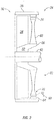
- fan rotor system 30 is a cold section rotating stage in the form of a single rotating fan blade stage having a wheel 32 and a plurality of fan blades 34 that are circumferentially surrounded by a fan shroud 36.
- shroud 36 is configured to retain one or more blades 34 within engine 10 during a blade-off event. In other embodiments, shroud 36 may not be so configured.
- Bypass duct 14 is operative to transmit a bypass flow generated by fan system 12 to nozzle 28.
- Compressor 16 includes a compressor rotor system 38, which are also referred to as cold section stages.
- compressor rotor system 38 includes one or more rotors (not shown) that are powered by turbine 22.
- Each compressor rotor includes a plurality of rows of compressor blades (not shown) that are alternatingly interspersed with rows of compressor vanes (not shown).
- the compressor blades are circumferentially surrounded by shrouds, e.g., in the form of blade tracks mounted on or formed as part of one or more compressor cases (not shown).
- Turbine 22 includes a turbine rotor system 40.
- turbine rotor system 40 includes one or more rotors (not shown) operative to drive fan rotor system 30 and compressor rotor system 38.
- Each turbine rotor includes a plurality of turbine blades (not shown) that are alternatingly interspersed with rows of turbine vanes (not shown).
- the turbine blades are circumferentially surrounded by shrouds, e.g., in the form of blade tracks mounted on or formed as part of one or more compressor cases (not shown).
- Electrical machine 24 is configured to generate electrical power. In one form, electrical machine 24 is disposed in (or adjacent to) fan system 12. In other embodiments, electrical machine 24 may be disposed within (or adjacent to) compressor 16. In various embodiments, electrical machine 24 may be configured as a generator, an alternator or any other type of electrical machine that is configured to generate electrical power.
- Turbine rotor system 40 is drivingly coupled to compressor rotor system 38 and fan rotor system 30 via a shafting system 42.
- shafting system 42 includes a plurality of shafts that may rotate at the same or different speeds and directions. In some embodiments, only a single shaft may be employed.
- Turbine 22 is operative to discharge an engine 10 core flow to nozzle 28.
- fan rotor system 30, compressor rotor system 38, turbine rotor system 40 and shafting system 42 rotate about an engine centerline 46. In other embodiments, all or parts of fan rotor system 30, compressor rotor system 38, turbine rotor system 40 and shafting system 42 may rotate about one or more other axes of rotation in addition to or in place of engine centerline 46.
- Discharge duct 26 extends between a discharge portion 48 of turbine 22 and engine nozzle 28. Discharge duct 26 is operative to direct bypass flow and core flow from a bypass duct discharge portion 44 and turbine discharge portion 48, respectively, into nozzle system 28. In some embodiments, discharge duct 26 may be considered a part of nozzle 28. Nozzle 28 is in fluid communication with fan system 12 and turbine 22. Nozzle 28 is operative to receive the bypass flow from fan system 12 via bypass duct 14, and to receive the core flow from turbine 22, and to discharge both as an engine exhaust flow, e.g., a thrust-producing flow. In other embodiments, other nozzle arrangements may be employed, including separate nozzles for each of the core flow and the bypass flow.
- air is drawn into the inlet of fan 12 and pressurized by fan 12.
- Some of the air pressurized by fan 12 is directed into compressor 16 as core flow, and some of the pressurized air is directed into bypass duct 14 as bypass flow, and is discharged into nozzle 28 via discharge duct 26.
- Compressor 16 further pressurizes the portion of the air received therein from fan 12, which is then discharged into diffuser 18.
- Diffuser 18 reduces the velocity of the pressurized air, and directs the diffused core airflow into combustor 20.
- Fuel is mixed with the pressurized air in combustor 20, which is then combusted.
- the hot gases exiting combustor 20 are directed into turbine 22, which extracts energy in the form of mechanical shaft power sufficient to drive fan system 12 and compressor 16 via shafting system 42.
- the core flow exiting turbine 22 is directed along an engine tail cone 50 and into discharge duct 26, along with the bypass flow from bypass duct 14.
- Discharge duct 26 is configured to receive the bypass flow and the core flow, and to discharge both as an engine exhaust flow, e.g., for providing thrust, such as for aircraft propulsion.
- Electrical machine 24 includes a stator 60 and a rotor 62, each of which includes electrical generating components.
- stator 60 and rotor 62 are disposed adjacent to fan blades 34.
- stator 60 and rotor 62 may be positioned adjacent to compressor blades in addition to or in place of fan blades 34.
- stator 60 is positioned adjacent to shroud 36. In other embodiments, stator 60 may be positioned within shroud 36.
- Stator 60 includes as an electrical generating component an armature component 64.
- armature component 64 is an armature winding.
- armature component 64 may be in the form of a continuous ring extending circumferentially around rotor 62, or may be formed of discreet armature elements, e.g., windings, spaced apart circumferentially around rotor 62. In other embodiments, armature component 64 may take other forms.
- Rotor 62 includes a hub 66, a plurality of struts 68, a plurality of rotor tips 70 and a plurality of electrical generating components in the form of field components 72.
- rotor 62 is configured to rotate the same speed as fan rotor stage 30 during the operation of engine 10. In other embodiments, rotor 62 may be configured to rotate at a different speed than fan rotor stage 30.
- hub 66 is formed integrally with wheel 32 as an extension of wheel 32. In other embodiments, hub 66 may be formed separately from wheel 32 and be coupled to wheel 32.
- Struts 68 extend radially outward from hub 66, culminating at rotor tips 70. Struts 68 are spaced apart circumferentially. Struts 68 are configured to support field components 72. In one form, each strut 68 is configured to support and radially retain a single field component 72 during the operation of engine 10. In other embodiments, each strut 68 may support and retain more than one field component 72. In one form, each strut 68 is positioned adjacent to a blade 34. In other embodiments, struts 68 may be positioned adjacent to a compressor blade in addition to or in place of blade 34.
- struts 68 are configured to rotate with blades 34, e.g., such that the position of each strut 68 relative to an adjacent blade 34 is maintained during the operation of engine 10.
- struts 68 are positioned downstream of blades 34, which in some embodiments may reduce or eliminate aerodynamic losses associated with struts 68.
- Rotor tips 70 are positioned proximate to stator 60 in an axial position different from that of blades 34. In one form, rotor tips 70 are positioned downstream of fan blades 34. In other embodiments, rotor tips 70 may be positioned upstream of fan blades 34.
- Field components 72 are disposed adjacent to stator 60. In one form, field components 72 are in the form of magnets. In other embodiments, field components 72 may take other forms. In a particular form, field components 72 are in the form of permanent magnets. In other embodiments, other types of magnets may be employed as field components 72 in addition to or in place of permanent magnets, for example and without limitation, electromagnets.
- Rotor 62 and stator 60 are configured to form a gap 74 therebetween, in particular, between field component 72 and armature component 64.
- electrical machine 24 is cooled by the airflow pressurized by fan rotor stage 30 that passes through gap 74.
- electrical machine 24 may be cooled by other means in addition to or in place of the airflow pressurized by fan rotor stage 30 passing through gap 74.
- Embodiments of the present disclosure include a gas turbine engine, comprising: a cold section stage being at least one of a fan blade stage and a compressor blade stage, wherein the cold section stage includes plurality of blades and a shroud circumferentially surrounding the plurality of blades; a combustor in fluid communication with the at least one of the fan blade stage and the compressor blade stage; a turbine in fluid communication with the combustor; and an electrical machine configured to generate electrical power, wherein the electrical machine includes a stator and a rotor; wherein the stator is positioned adjacent to or within the shroud; and wherein the rotor includes a rotor tip positioned proximate to the stator and in a different axial location than the blades.
- the stator includes an armature component positioned adjacent to or within the shroud; and wherein the rotor tip includes a field component positioned proximate to the stator.
- the armature component is an armature winding; and wherein the field component is a magnet.
- the rotor includes a hub and a strut extending from the hub, wherein the strut is configured to support the field component.
- the strut is positioned adjacent to a blade of the cold section stage.
- the strut is positioned downstream of the blade.
- the strut is configured to rotate with the blade.
- the cold section stage includes a wheel; wherein the rotor includes a hub and a strut extending from the hub; wherein the strut is configured to support the field component; and wherein the hub is coupled to the wheel or is formed as an extension of the wheel.
- the rotor is configured to operate at the same rotational speed as the cold section stage during operation of the gas turbine engine.
- the electrical machine is cooled by airflow pressurized by the cold section stage.
- the rotor and the stator are configured to form a gap between the rotor and stator; and wherein the electrical machine is cooled by the airflow passing through the gap.
- Embodiments of the present disclosure include a gas turbine engine, comprising: at least one of a rotating fan stage and a rotating compressor stage; a combustor in fluid communication with the at least one of the rotating fan stage and the rotating compressor stage; at least one rotating turbine stage in fluid communication with the combustor; and an electrical machine configured to generate electrical power, wherein the electrical machine includes a stator and a rotor; wherein the at least one of the rotating fan stage and the rotating compressor stage include a shroud circumferentially surrounding a plurality of blades of the at least one of the rotating fan stage and the rotating compressor stage ; and wherein the stator is positioned adjacent to or within the shroud; and wherein the rotor includes a rotor tip positioned proximate to the stator and in a different axial location than the blades.
- the stator includes an armature component positioned adjacent to or within the shroud; and wherein the rotor tip includes a field component positioned proximate to the stator.
- the at least one of the rotating fan stage and the rotating compressor stage includes a wheel; wherein the rotor includes a hub and a strut extending from the hub; wherein the strut is configured as part of the rotor; and wherein the hub is coupled to the wheel or is formed as an extension of the wheel.
- the rotor is configured to operate at the same rotational speed as the at least one of the rotating fan stage and the rotating compressor stage during operation of the gas turbine engine.
- the rotor includes a hub and a strut extending from the hub.
- the strut is positioned adjacent to a blade of the at least one of the rotating fan stage and the rotating compressor stage
- the strut is configured to rotate with the blade.
- Embodiments of the present disclosure include a gas turbine engine, comprising: at least one of a rotating fan stage and a rotating compressor stage; a combustor in fluid communication with the at least one of the rotating fan stage and the rotating compressor stage; at least one rotating turbine stage in fluid communication with the combustor; and means for generating electrical power disposed adjacent to the at least one of the rotating fan stage and the rotating compressor stage.
- the means for generating electrical power includes a stator, a rotor having struts and first electrical generating components disposed at tips of the struts; wherein the struts are positioned adjacent to and configured to rotate with the at least one of the rotating fan stage and the rotating compressor stage ; wherein the at least one of the rotating fan stage and the rotating compressor stage include a shroud; wherein the stator includes second electrical generating components positioned adjacent to or within the shroud.
Landscapes
- Engineering & Computer Science (AREA)
- Mechanical Engineering (AREA)
- General Engineering & Computer Science (AREA)
- Power Engineering (AREA)
- Chemical & Material Sciences (AREA)
- Combustion & Propulsion (AREA)
- Structures Of Non-Positive Displacement Pumps (AREA)
- Connection Of Motors, Electrical Generators, Mechanical Devices, And The Like (AREA)
Claims (10)
- Moteur à turbine à gaz (10) comprenant :au moins l'un parmi un étage de ventilateur rotatif (30) et un étage de compresseur rotatif (38) ;une chambre de combustion (20) en communication de fluide avec au moins l'un parmi l'étage de ventilateur rotatif (30) et l'étage de compresseur rotatif (38) ;au moins un étage de turbine rotative (40) en communication de fluide avec la chambre de combustion (20) ;dans lequel le au moins un parmi l'étage de ventilateur rotatif (30) et l'étage de compresseur rotatif (38) comprend un flasque (36) entourant, de manière circonférentielle, une pluralité de pales (34) d'au moins l'un parmi l'étage de ventilateur rotatif (30) et l'étage de compresseur rotatif (38) ; etune machine électrique (24) comprenant un stator (60) et un rotor (62) et étant configurée pour générer de l'énergie électrique,dans lequel le stator (60) est positionné de manière adjacente à ou à l'intérieur du flasque (36) ; et caractérisé en ce que :
le rotor (62) comprend un moyeu (66), une pluralité d'entretoises (68), une pluralité de pointes de rotor (70) et une pluralité de composants de génération d'électricité se présentant sous la forme de composants de champ (72), les entretoises (68) s'étendent radialement vers l'extérieur à partir du moyeu (66) culminant au niveau des pointes de rotor (70), les entretoises (68) sont espacées de manière circonférentielle et configurées pour supporter les composants de champ (72) et les pointes de rotor (70) sont positionnées à proximité du stator (60) et dans un emplacement axial différent des pales (34). - Moteur à turbine à gaz (10) selon la revendication 1, dans lequel la machine électrique (24) est refroidie par écoulement d'air mis sous pression par au moins l'un parmi l'étage de ventilateur rotatif (30) et l'étage de compresseur rotatif (38).
- Moteur à turbine à gaz (10) selon l'une quelconque des revendications 1 ou 2, dans lequel le au moins un parmi l'étage de ventilateur rotatif (30) et l'étage de compresseur rotatif (38) comprend une roue (32) ;
dans lequel l'entretoise (68) est configurée comme faisant partie du rotor (62) ; et dans lequel le moyeu (66) est couplé à la roue (32) ou est formé comme une extension de la roue (32). - Moteur à turbine à gaz (10) selon l'une quelconque des revendications précédentes, dans lequel le rotor (62) est configuré pour fonctionner à la même vitesse de rotation que le au moins un parmi l'étage de ventilateur rotatif (30) et l'étage de compresseur rotatif (38) pendant le fonctionnement du moteur à turbine à gaz (10).
- Moteur à turbine à gaz (10) selon l'une quelconque des revendications 2 à 4, dans lequel l'entretoise (68) est positionnée de manière adjacente à une pale (34) du au moins un parmi l'étage de ventilateur rotatif (30) et l'étage de compresseur rotatif (38).
- Utilisation d'une machine électrique (24) comprenant un stator (60) et un rotor (62) et étant configurée pour générer de l'énergie électrique, dans le moteur à turbine à gaz (10) ;
dans laquelle le stator (60) est positionné de manière adjacente à ou à l'intérieur d'un flasque (36) d'un étage de section froide (30, 38) qui est au moins l'un parmi un étage de pale de ventilateur et un étage de pale de compresseur du moteur à turbine à gaz (10),
dans laquelle l'étage de section froide (30, 38) comprend une pluralité de pales (34) et le flasque (36) entourant de manière circonférentielle la pluralité de pales (34) du moteur à turbine à gaz (10) ; et
dans laquelle le rotor (62) comprend un moyeu (66), une pluralité d'entretoises (68), une pluralité de pointes de rotor (70) et une pluralité de composants de génération d'électricité se présentant sous la forme de composants de champ (72), les entretoises (68) s'étendent radialement vers l'extérieur à partir du moyeu (66) culminant au niveau des pointes de rotor (70),
dans laquelle les entretoises (68) sont espacées de manière circonférentielle et configurées pour supporter les composants de champ (72), et dans laquelle les pointes de rotor (70) sont positionnées à proximité du stator (60) et dans un emplacement axial différent de la pluralité de pales (34). - Utilisation selon la revendication 6, le machine électrique (24) est refroidie par un écoulement d'air mis sous pression par au moins l'un parmi l'étage de ventilateur rotatif (30) et l'étage de compresseur rotatif (38).
- Utilisation selon la revendication 6 ou 7, dans laquelle le au moins un parmi l'étage de ventilateur rotatif (30) et l'étage de compresseur rotatif (38) comprend une roue (32) ; dans laquelle l'entretoise (68) s'étend à partir du moyeu (66) du rotor (62) ; dans laquelle l'entretoise (68) est configurée comme faisant partie du rotor (62) ; et dans laquelle le moyeu (66) est couplé à la roue (32) ou est formé comme une extension de la roue (32).
- Utilisation selon l'une quelconque des revendications 6 à 8, dans laquelle le rotor (62) est configuré pour fonctionner à la même vitesse de rotation que le au moins un parmi l'étage de ventilateur rotatif (30) et l'étage de compresseur rotatif (38) pendant le fonctionnement du moteur à turbine à gaz (10).
- Utilisation selon l'une quelconque des revendications 6 à 9, dans laquelle l'entretoise (68) est positionnée de manière adjacente à une pale (34) d'au moins l'un parmi l'étage de ventilateur rotatif (30) et l'étage de compresseur rotatif (38).
Applications Claiming Priority (2)
| Application Number | Priority Date | Filing Date | Title |
|---|---|---|---|
| US201361771891P | 2013-03-03 | 2013-03-03 | |
| PCT/US2013/072068 WO2014137424A1 (fr) | 2013-03-03 | 2013-11-26 | Moteur à turbine à gaz |
Publications (2)
| Publication Number | Publication Date |
|---|---|
| EP2964904A1 EP2964904A1 (fr) | 2016-01-13 |
| EP2964904B1 true EP2964904B1 (fr) | 2020-10-14 |
Family
ID=49780374
Family Applications (1)
| Application Number | Title | Priority Date | Filing Date |
|---|---|---|---|
| EP13808356.3A Active EP2964904B1 (fr) | 2013-03-03 | 2013-11-26 | Moteur à turbine à gaz |
Country Status (4)
| Country | Link |
|---|---|
| US (1) | US9077221B2 (fr) |
| EP (1) | EP2964904B1 (fr) |
| CA (1) | CA2903320C (fr) |
| WO (1) | WO2014137424A1 (fr) |
Families Citing this family (6)
| Publication number | Priority date | Publication date | Assignee | Title |
|---|---|---|---|---|
| US10826344B2 (en) | 2016-11-17 | 2020-11-03 | General Electric Company | High speed electric machine with embedded rotor magnets |
| GB201710403D0 (en) * | 2017-06-29 | 2017-08-16 | Rolls Royce Plc | Electrical machine apparatus |
| FR3087822B1 (fr) | 2018-10-26 | 2020-11-06 | Safran Aircraft Engines | Turbomachine a machine electrique comportant un anneau de rotor accole a la soufflante |
| US11739694B2 (en) | 2020-04-15 | 2023-08-29 | General Electric Company | Embedded electric motor assembly |
| GB202307055D0 (en) * | 2023-05-12 | 2023-06-28 | Rolls Royce Plc | An accessory power module |
| US12448893B1 (en) | 2024-07-29 | 2025-10-21 | Pratt & Whitney Canada Corp. | Electromagnetic inducer for gas turbine rotating turbomachinery |
Citations (1)
| Publication number | Priority date | Publication date | Assignee | Title |
|---|---|---|---|---|
| US20120133150A1 (en) * | 2010-11-29 | 2012-05-31 | Pratt & Whitney Canada Corp. | Combination low spool generator and ram air turbine generator |
Family Cites Families (20)
| Publication number | Priority date | Publication date | Assignee | Title |
|---|---|---|---|---|
| US3859785A (en) | 1973-12-17 | 1975-01-14 | Curtiss Wright Corp | Turbine engine with integral compressor and alternator rotor |
| DE2823261C2 (de) * | 1978-05-27 | 1985-05-23 | Robert Bosch Gmbh, 7000 Stuttgart | Elektrische Maschine |
| US4555637A (en) * | 1982-07-26 | 1985-11-26 | Acd, Inc. | High speed turbogenerator for power recovery from fluid flow within conduit |
| US5376827A (en) * | 1993-05-27 | 1994-12-27 | General Electric Company | Integrated turbine-generator |
| GB2372157B (en) | 2001-02-09 | 2005-07-06 | Rolls Royce Plc | A gas turbine with an electrical machine |
| DE10359559A1 (de) | 2003-12-18 | 2005-07-28 | Mtu Aero Engines Gmbh | Gasturbine, insbesondere Flugtriebwerk |
| DE102004004945A1 (de) | 2004-01-31 | 2005-08-18 | Mtu Aero Engines Gmbh | Gasturbine, insbesondere Flugtriebwerk |
| GB2410982A (en) * | 2004-02-14 | 2005-08-17 | Richard Julius Gozdawa | Turbomachinery electric generator arrangement with component cooling |
| US7251942B2 (en) | 2004-06-29 | 2007-08-07 | Honeywell International Inc. | Integrated gearless and nonlubricated auxiliary power unit |
| US7285871B2 (en) * | 2004-08-25 | 2007-10-23 | Honeywell International, Inc. | Engine power extraction control system |
| FR2878286B1 (fr) | 2004-11-25 | 2009-05-22 | Snecma Moteurs Sa | Turbomachine comportant un generateur de courant electrique integre |
| US20060137355A1 (en) * | 2004-12-27 | 2006-06-29 | Pratt & Whitney Canada Corp. | Fan driven emergency generator |
| DE102005046208A1 (de) * | 2005-09-28 | 2007-03-29 | Mtu Aero Engines Gmbh | Strahltriebwerk |
| US7802757B2 (en) * | 2005-11-09 | 2010-09-28 | Pratt & Whitney Canada Corp. | Method and system for taxiing an aircraft |
| DE102006003884A1 (de) * | 2006-01-27 | 2007-08-02 | Mtu Aero Engines Gmbh | Strahltriebwerk mit aktivmagnetischer Lagerung |
| US7603864B2 (en) * | 2006-11-29 | 2009-10-20 | General Electric Company | Blade tip electric machine |
| US8803354B2 (en) * | 2006-12-20 | 2014-08-12 | Unimodal Systems Llc | Modular electric generator for variable speed turbines |
| FR2921978B1 (fr) | 2007-10-08 | 2014-04-11 | Snecma | Turboreacteur a generateur electrique agence dans la soufflante |
| US8745990B2 (en) * | 2009-07-27 | 2014-06-10 | Rolls-Royce Corporation | Gas turbine engine with integrated electric starter/generator |
| US8522522B2 (en) * | 2010-07-30 | 2013-09-03 | Hamilton Sundstrand Corporation | Fan embedded power generator |
-
2013
- 2013-11-26 CA CA2903320A patent/CA2903320C/fr not_active Expired - Fee Related
- 2013-11-26 EP EP13808356.3A patent/EP2964904B1/fr active Active
- 2013-11-26 WO PCT/US2013/072068 patent/WO2014137424A1/fr not_active Ceased
- 2013-12-13 US US14/105,370 patent/US9077221B2/en active Active
Patent Citations (1)
| Publication number | Priority date | Publication date | Assignee | Title |
|---|---|---|---|---|
| US20120133150A1 (en) * | 2010-11-29 | 2012-05-31 | Pratt & Whitney Canada Corp. | Combination low spool generator and ram air turbine generator |
Also Published As
| Publication number | Publication date |
|---|---|
| EP2964904A1 (fr) | 2016-01-13 |
| CA2903320C (fr) | 2019-07-16 |
| US20140246864A1 (en) | 2014-09-04 |
| CA2903320A1 (fr) | 2014-09-12 |
| US9077221B2 (en) | 2015-07-07 |
| WO2014137424A1 (fr) | 2014-09-12 |
Similar Documents
| Publication | Publication Date | Title |
|---|---|---|
| EP2805022B1 (fr) | Système d'une aube statorique d'une turbine à gaz à double flux, turbine à gaz, et méthode de fabrication d'un étage d'aubes statoriques à double flux | |
| CA2762810C (fr) | Systeme de deflecteurs a geometrie variable pour moteurs a turbine a gaz | |
| EP2472062B1 (fr) | Moteur de turbine à gaz et l'aube | |
| EP2937515B1 (fr) | Moteur à turbine à gaz doté d'une plateforme de pale de rotor contourée à surface non axisymétrique | |
| US10677164B2 (en) | Cooling system for a turbine engine | |
| US9091172B2 (en) | Rotor with cooling passage | |
| EP2372102A2 (fr) | Plate-forme des pales de rotor d'une turbine à gaz | |
| US9077221B2 (en) | Gas turbine engine | |
| US20140311164A1 (en) | Gas turbine engine and turbine blade | |
| EP2809882B1 (fr) | Dentelures d'air de soutirage de disques de compresseur | |
| US20180216576A1 (en) | Supersonic turbofan engine | |
| CN106050314A (zh) | 涡轮框架和用于涡轮框架的翼型件 | |
| US9638056B2 (en) | Gas turbine engine and active balancing system | |
| US20150260127A1 (en) | Aircraft Turbofan Engine with Multiple High-Pressure Core Modules Not Concentric with the Engine Centerline | |
| EP3203023A1 (fr) | Moteur à turbine à gaz ayant un trajet de fluide de refroidissement | |
| US11549463B2 (en) | Compact low-pressure compressor | |
| US10711648B2 (en) | Nosecone support |
Legal Events
| Date | Code | Title | Description |
|---|---|---|---|
| PUAI | Public reference made under article 153(3) epc to a published international application that has entered the european phase |
Free format text: ORIGINAL CODE: 0009012 |
|
| 17P | Request for examination filed |
Effective date: 20150923 |
|
| AK | Designated contracting states |
Kind code of ref document: A1 Designated state(s): AL AT BE BG CH CY CZ DE DK EE ES FI FR GB GR HR HU IE IS IT LI LT LU LV MC MK MT NL NO PL PT RO RS SE SI SK SM TR |
|
| AX | Request for extension of the european patent |
Extension state: BA ME |
|
| DAX | Request for extension of the european patent (deleted) | ||
| STAA | Information on the status of an ep patent application or granted ep patent |
Free format text: STATUS: EXAMINATION IS IN PROGRESS |
|
| 17Q | First examination report despatched |
Effective date: 20180606 |
|
| GRAP | Despatch of communication of intention to grant a patent |
Free format text: ORIGINAL CODE: EPIDOSNIGR1 |
|
| STAA | Information on the status of an ep patent application or granted ep patent |
Free format text: STATUS: GRANT OF PATENT IS INTENDED |
|
| INTG | Intention to grant announced |
Effective date: 20200520 |
|
| GRAS | Grant fee paid |
Free format text: ORIGINAL CODE: EPIDOSNIGR3 |
|
| GRAA | (expected) grant |
Free format text: ORIGINAL CODE: 0009210 |
|
| STAA | Information on the status of an ep patent application or granted ep patent |
Free format text: STATUS: THE PATENT HAS BEEN GRANTED |
|
| AK | Designated contracting states |
Kind code of ref document: B1 Designated state(s): AL AT BE BG CH CY CZ DE DK EE ES FI FR GB GR HR HU IE IS IT LI LT LU LV MC MK MT NL NO PL PT RO RS SE SI SK SM TR |
|
| REG | Reference to a national code |
Ref country code: GB Ref legal event code: FG4D |
|
| REG | Reference to a national code |
Ref country code: AT Ref legal event code: REF Ref document number: 1323801 Country of ref document: AT Kind code of ref document: T Effective date: 20201015 Ref country code: CH Ref legal event code: EP |
|
| REG | Reference to a national code |
Ref country code: DE Ref legal event code: R096 Ref document number: 602013073313 Country of ref document: DE |
|
| REG | Reference to a national code |
Ref country code: IE Ref legal event code: FG4D |
|
| REG | Reference to a national code |
Ref country code: AT Ref legal event code: MK05 Ref document number: 1323801 Country of ref document: AT Kind code of ref document: T Effective date: 20201014 |
|
| REG | Reference to a national code |
Ref country code: NL Ref legal event code: MP Effective date: 20201014 |
|
| PG25 | Lapsed in a contracting state [announced via postgrant information from national office to epo] |
Ref country code: NL Free format text: LAPSE BECAUSE OF FAILURE TO SUBMIT A TRANSLATION OF THE DESCRIPTION OR TO PAY THE FEE WITHIN THE PRESCRIBED TIME-LIMIT Effective date: 20201014 Ref country code: NO Free format text: LAPSE BECAUSE OF FAILURE TO SUBMIT A TRANSLATION OF THE DESCRIPTION OR TO PAY THE FEE WITHIN THE PRESCRIBED TIME-LIMIT Effective date: 20210114 Ref country code: PT Free format text: LAPSE BECAUSE OF FAILURE TO SUBMIT A TRANSLATION OF THE DESCRIPTION OR TO PAY THE FEE WITHIN THE PRESCRIBED TIME-LIMIT Effective date: 20210215 Ref country code: FI Free format text: LAPSE BECAUSE OF FAILURE TO SUBMIT A TRANSLATION OF THE DESCRIPTION OR TO PAY THE FEE WITHIN THE PRESCRIBED TIME-LIMIT Effective date: 20201014 Ref country code: RS Free format text: LAPSE BECAUSE OF FAILURE TO SUBMIT A TRANSLATION OF THE DESCRIPTION OR TO PAY THE FEE WITHIN THE PRESCRIBED TIME-LIMIT Effective date: 20201014 Ref country code: GR Free format text: LAPSE BECAUSE OF FAILURE TO SUBMIT A TRANSLATION OF THE DESCRIPTION OR TO PAY THE FEE WITHIN THE PRESCRIBED TIME-LIMIT Effective date: 20210115 |
|
| REG | Reference to a national code |
Ref country code: LT Ref legal event code: MG4D |
|
| PG25 | Lapsed in a contracting state [announced via postgrant information from national office to epo] |
Ref country code: ES Free format text: LAPSE BECAUSE OF FAILURE TO SUBMIT A TRANSLATION OF THE DESCRIPTION OR TO PAY THE FEE WITHIN THE PRESCRIBED TIME-LIMIT Effective date: 20201014 Ref country code: AT Free format text: LAPSE BECAUSE OF FAILURE TO SUBMIT A TRANSLATION OF THE DESCRIPTION OR TO PAY THE FEE WITHIN THE PRESCRIBED TIME-LIMIT Effective date: 20201014 Ref country code: BG Free format text: LAPSE BECAUSE OF FAILURE TO SUBMIT A TRANSLATION OF THE DESCRIPTION OR TO PAY THE FEE WITHIN THE PRESCRIBED TIME-LIMIT Effective date: 20210114 Ref country code: IS Free format text: LAPSE BECAUSE OF FAILURE TO SUBMIT A TRANSLATION OF THE DESCRIPTION OR TO PAY THE FEE WITHIN THE PRESCRIBED TIME-LIMIT Effective date: 20210214 Ref country code: LV Free format text: LAPSE BECAUSE OF FAILURE TO SUBMIT A TRANSLATION OF THE DESCRIPTION OR TO PAY THE FEE WITHIN THE PRESCRIBED TIME-LIMIT Effective date: 20201014 Ref country code: PL Free format text: LAPSE BECAUSE OF FAILURE TO SUBMIT A TRANSLATION OF THE DESCRIPTION OR TO PAY THE FEE WITHIN THE PRESCRIBED TIME-LIMIT Effective date: 20201014 Ref country code: SE Free format text: LAPSE BECAUSE OF FAILURE TO SUBMIT A TRANSLATION OF THE DESCRIPTION OR TO PAY THE FEE WITHIN THE PRESCRIBED TIME-LIMIT Effective date: 20201014 |
|
| REG | Reference to a national code |
Ref country code: DE Ref legal event code: R119 Ref document number: 602013073313 Country of ref document: DE |
|
| PG25 | Lapsed in a contracting state [announced via postgrant information from national office to epo] |
Ref country code: HR Free format text: LAPSE BECAUSE OF FAILURE TO SUBMIT A TRANSLATION OF THE DESCRIPTION OR TO PAY THE FEE WITHIN THE PRESCRIBED TIME-LIMIT Effective date: 20201014 |
|
| REG | Reference to a national code |
Ref country code: CH Ref legal event code: PL |
|
| PG25 | Lapsed in a contracting state [announced via postgrant information from national office to epo] |
Ref country code: LT Free format text: LAPSE BECAUSE OF FAILURE TO SUBMIT A TRANSLATION OF THE DESCRIPTION OR TO PAY THE FEE WITHIN THE PRESCRIBED TIME-LIMIT Effective date: 20201014 Ref country code: MC Free format text: LAPSE BECAUSE OF FAILURE TO SUBMIT A TRANSLATION OF THE DESCRIPTION OR TO PAY THE FEE WITHIN THE PRESCRIBED TIME-LIMIT Effective date: 20201014 Ref country code: LU Free format text: LAPSE BECAUSE OF NON-PAYMENT OF DUE FEES Effective date: 20201126 Ref country code: SK Free format text: LAPSE BECAUSE OF FAILURE TO SUBMIT A TRANSLATION OF THE DESCRIPTION OR TO PAY THE FEE WITHIN THE PRESCRIBED TIME-LIMIT Effective date: 20201014 Ref country code: RO Free format text: LAPSE BECAUSE OF FAILURE TO SUBMIT A TRANSLATION OF THE DESCRIPTION OR TO PAY THE FEE WITHIN THE PRESCRIBED TIME-LIMIT Effective date: 20201014 Ref country code: SM Free format text: LAPSE BECAUSE OF FAILURE TO SUBMIT A TRANSLATION OF THE DESCRIPTION OR TO PAY THE FEE WITHIN THE PRESCRIBED TIME-LIMIT Effective date: 20201014 Ref country code: CZ Free format text: LAPSE BECAUSE OF FAILURE TO SUBMIT A TRANSLATION OF THE DESCRIPTION OR TO PAY THE FEE WITHIN THE PRESCRIBED TIME-LIMIT Effective date: 20201014 Ref country code: EE Free format text: LAPSE BECAUSE OF FAILURE TO SUBMIT A TRANSLATION OF THE DESCRIPTION OR TO PAY THE FEE WITHIN THE PRESCRIBED TIME-LIMIT Effective date: 20201014 |
|
| REG | Reference to a national code |
Ref country code: BE Ref legal event code: MM Effective date: 20201130 |
|
| PLBE | No opposition filed within time limit |
Free format text: ORIGINAL CODE: 0009261 |
|
| STAA | Information on the status of an ep patent application or granted ep patent |
Free format text: STATUS: NO OPPOSITION FILED WITHIN TIME LIMIT |
|
| PG25 | Lapsed in a contracting state [announced via postgrant information from national office to epo] |
Ref country code: CH Free format text: LAPSE BECAUSE OF NON-PAYMENT OF DUE FEES Effective date: 20201130 Ref country code: DK Free format text: LAPSE BECAUSE OF FAILURE TO SUBMIT A TRANSLATION OF THE DESCRIPTION OR TO PAY THE FEE WITHIN THE PRESCRIBED TIME-LIMIT Effective date: 20201014 Ref country code: LI Free format text: LAPSE BECAUSE OF NON-PAYMENT OF DUE FEES Effective date: 20201130 |
|
| 26N | No opposition filed |
Effective date: 20210715 |
|
| GBPC | Gb: european patent ceased through non-payment of renewal fee |
Effective date: 20210114 |
|
| PG25 | Lapsed in a contracting state [announced via postgrant information from national office to epo] |
Ref country code: AL Free format text: LAPSE BECAUSE OF FAILURE TO SUBMIT A TRANSLATION OF THE DESCRIPTION OR TO PAY THE FEE WITHIN THE PRESCRIBED TIME-LIMIT Effective date: 20201014 Ref country code: IT Free format text: LAPSE BECAUSE OF FAILURE TO SUBMIT A TRANSLATION OF THE DESCRIPTION OR TO PAY THE FEE WITHIN THE PRESCRIBED TIME-LIMIT Effective date: 20201014 Ref country code: IE Free format text: LAPSE BECAUSE OF NON-PAYMENT OF DUE FEES Effective date: 20201126 |
|
| PG25 | Lapsed in a contracting state [announced via postgrant information from national office to epo] |
Ref country code: SI Free format text: LAPSE BECAUSE OF FAILURE TO SUBMIT A TRANSLATION OF THE DESCRIPTION OR TO PAY THE FEE WITHIN THE PRESCRIBED TIME-LIMIT Effective date: 20201014 Ref country code: GB Free format text: LAPSE BECAUSE OF NON-PAYMENT OF DUE FEES Effective date: 20210114 Ref country code: DE Free format text: LAPSE BECAUSE OF NON-PAYMENT OF DUE FEES Effective date: 20210601 |
|
| PG25 | Lapsed in a contracting state [announced via postgrant information from national office to epo] |
Ref country code: IS Free format text: LAPSE BECAUSE OF FAILURE TO SUBMIT A TRANSLATION OF THE DESCRIPTION OR TO PAY THE FEE WITHIN THE PRESCRIBED TIME-LIMIT Effective date: 20210214 Ref country code: TR Free format text: LAPSE BECAUSE OF FAILURE TO SUBMIT A TRANSLATION OF THE DESCRIPTION OR TO PAY THE FEE WITHIN THE PRESCRIBED TIME-LIMIT Effective date: 20201014 Ref country code: MT Free format text: LAPSE BECAUSE OF FAILURE TO SUBMIT A TRANSLATION OF THE DESCRIPTION OR TO PAY THE FEE WITHIN THE PRESCRIBED TIME-LIMIT Effective date: 20201014 Ref country code: CY Free format text: LAPSE BECAUSE OF FAILURE TO SUBMIT A TRANSLATION OF THE DESCRIPTION OR TO PAY THE FEE WITHIN THE PRESCRIBED TIME-LIMIT Effective date: 20201014 |
|
| PG25 | Lapsed in a contracting state [announced via postgrant information from national office to epo] |
Ref country code: MK Free format text: LAPSE BECAUSE OF FAILURE TO SUBMIT A TRANSLATION OF THE DESCRIPTION OR TO PAY THE FEE WITHIN THE PRESCRIBED TIME-LIMIT Effective date: 20201014 |
|
| PG25 | Lapsed in a contracting state [announced via postgrant information from national office to epo] |
Ref country code: BE Free format text: LAPSE BECAUSE OF NON-PAYMENT OF DUE FEES Effective date: 20201130 |
|
| P01 | Opt-out of the competence of the unified patent court (upc) registered |
Effective date: 20230528 |
|
| PGFP | Annual fee paid to national office [announced via postgrant information from national office to epo] |
Ref country code: FR Payment date: 20231123 Year of fee payment: 11 |
|
| PG25 | Lapsed in a contracting state [announced via postgrant information from national office to epo] |
Ref country code: FR Free format text: LAPSE BECAUSE OF NON-PAYMENT OF DUE FEES Effective date: 20241130 |