EP2964960B1 - Compresseur centrifuge de moteur à turbine à gaz avec joint d'étanchéité entre deux parties de diffuseur - Google Patents
Compresseur centrifuge de moteur à turbine à gaz avec joint d'étanchéité entre deux parties de diffuseur Download PDFInfo
- Publication number
- EP2964960B1 EP2964960B1 EP13808423.1A EP13808423A EP2964960B1 EP 2964960 B1 EP2964960 B1 EP 2964960B1 EP 13808423 A EP13808423 A EP 13808423A EP 2964960 B1 EP2964960 B1 EP 2964960B1
- Authority
- EP
- European Patent Office
- Prior art keywords
- diffuser
- seal
- wall
- assembly
- radial
- Prior art date
- Legal status (The legal status is an assumption and is not a legal conclusion. Google has not performed a legal analysis and makes no representation as to the accuracy of the status listed.)
- Not-in-force
Links
Images

Classifications
-
- F—MECHANICAL ENGINEERING; LIGHTING; HEATING; WEAPONS; BLASTING
- F01—MACHINES OR ENGINES IN GENERAL; ENGINE PLANTS IN GENERAL; STEAM ENGINES
- F01D—NON-POSITIVE DISPLACEMENT MACHINES OR ENGINES, e.g. STEAM TURBINES
- F01D11/00—Preventing or minimising internal leakage of working-fluid, e.g. between stages
- F01D11/005—Sealing means between non relatively rotating elements
-
- F—MECHANICAL ENGINEERING; LIGHTING; HEATING; WEAPONS; BLASTING
- F01—MACHINES OR ENGINES IN GENERAL; ENGINE PLANTS IN GENERAL; STEAM ENGINES
- F01D—NON-POSITIVE DISPLACEMENT MACHINES OR ENGINES, e.g. STEAM TURBINES
- F01D9/00—Stators
- F01D9/06—Fluid supply conduits to nozzles or the like
- F01D9/065—Fluid supply or removal conduits traversing the working fluid flow, e.g. for lubrication-, cooling-, or sealing fluids
-
- F—MECHANICAL ENGINEERING; LIGHTING; HEATING; WEAPONS; BLASTING
- F02—COMBUSTION ENGINES; HOT-GAS OR COMBUSTION-PRODUCT ENGINE PLANTS
- F02C—GAS-TURBINE PLANTS; AIR INTAKES FOR JET-PROPULSION PLANTS; CONTROLLING FUEL SUPPLY IN AIR-BREATHING JET-PROPULSION PLANTS
- F02C7/00—Features, components parts, details or accessories, not provided for in, or of interest apart form groups F02C1/00 - F02C6/00; Air intakes for jet-propulsion plants
- F02C7/28—Arrangement of seals
-
- F—MECHANICAL ENGINEERING; LIGHTING; HEATING; WEAPONS; BLASTING
- F04—POSITIVE - DISPLACEMENT MACHINES FOR LIQUIDS; PUMPS FOR LIQUIDS OR ELASTIC FLUIDS
- F04D—NON-POSITIVE-DISPLACEMENT PUMPS
- F04D29/00—Details, component parts, or accessories
- F04D29/08—Sealings
- F04D29/083—Sealings especially adapted for elastic fluid pumps
-
- F—MECHANICAL ENGINEERING; LIGHTING; HEATING; WEAPONS; BLASTING
- F04—POSITIVE - DISPLACEMENT MACHINES FOR LIQUIDS; PUMPS FOR LIQUIDS OR ELASTIC FLUIDS
- F04D—NON-POSITIVE-DISPLACEMENT PUMPS
- F04D29/00—Details, component parts, or accessories
- F04D29/40—Casings; Connections of working fluid
- F04D29/42—Casings; Connections of working fluid for radial or helico-centrifugal pumps
- F04D29/44—Fluid-guiding means, e.g. diffusers
- F04D29/441—Fluid-guiding means, e.g. diffusers especially adapted for elastic fluid pumps
- F04D29/444—Bladed diffusers
-
- F—MECHANICAL ENGINEERING; LIGHTING; HEATING; WEAPONS; BLASTING
- F05—INDEXING SCHEMES RELATING TO ENGINES OR PUMPS IN VARIOUS SUBCLASSES OF CLASSES F01-F04
- F05D—INDEXING SCHEME FOR ASPECTS RELATING TO NON-POSITIVE-DISPLACEMENT MACHINES OR ENGINES, GAS-TURBINES OR JET-PROPULSION PLANTS
- F05D2230/00—Manufacture
- F05D2230/60—Assembly methods
- F05D2230/64—Assembly methods using positioning or alignment devices for aligning or centring, e.g. pins
- F05D2230/642—Assembly methods using positioning or alignment devices for aligning or centring, e.g. pins using maintaining alignment while permitting differential dilatation
-
- F—MECHANICAL ENGINEERING; LIGHTING; HEATING; WEAPONS; BLASTING
- F05—INDEXING SCHEMES RELATING TO ENGINES OR PUMPS IN VARIOUS SUBCLASSES OF CLASSES F01-F04
- F05D—INDEXING SCHEME FOR ASPECTS RELATING TO NON-POSITIVE-DISPLACEMENT MACHINES OR ENGINES, GAS-TURBINES OR JET-PROPULSION PLANTS
- F05D2250/00—Geometry
- F05D2250/50—Inlet or outlet
- F05D2250/52—Outlet
-
- Y—GENERAL TAGGING OF NEW TECHNOLOGICAL DEVELOPMENTS; GENERAL TAGGING OF CROSS-SECTIONAL TECHNOLOGIES SPANNING OVER SEVERAL SECTIONS OF THE IPC; TECHNICAL SUBJECTS COVERED BY FORMER USPC CROSS-REFERENCE ART COLLECTIONS [XRACs] AND DIGESTS
- Y10—TECHNICAL SUBJECTS COVERED BY FORMER USPC
- Y10T—TECHNICAL SUBJECTS COVERED BY FORMER US CLASSIFICATION
- Y10T29/00—Metal working
- Y10T29/49—Method of mechanical manufacture
- Y10T29/49316—Impeller making
- Y10T29/4932—Turbomachine making
- Y10T29/49321—Assembling individual fluid flow interacting members, e.g., blades, vanes, buckets, on rotary support member
Definitions
- An improved diffuser system for a centrifugal compressor is disclosed, and more particularly, a centrifugal compressor assembly including a radial diffuser section that is isolated from a structural load path of an axial diffuser section of the centrifugal compressor assembly.
- Gas turbine engines such as those used as aircraft propulsion units include turbojet and turbofan types.
- a turbofan engine includes a fan section, a compression section, a combustion section, a high pressure turbine section and a low pressure turbine section.
- the fan section is coupled to the low pressure turbine section while the compression section is coupled to the high pressure turbine section.
- the compression section together with the combustion section and the high pressure turbine section form the core of the engine.
- the compression section can be a single unit driven by the high pressure turbine or it may be split into an intermediate pressure compressor section followed by a high pressure compressor section driven by an intermediate pressure turbine and a high pressure turbine respectively.
- the compression sections can include axial compression stages, centrifugal stages or a combination of both.
- the centrifugal compressor typically includes a centrifugal impeller having blades that are enshrouded by a static impeller shroud. Minimizing the clearance between the impeller blades and the impeller shroud optimizes the capacity of the impeller in pressurizing air to the elevated pressures desired for peak engine performance.
- the shroud for a centrifugal compressor is typically mounted to an adjacent compressor casing if present, or to a downstream diffuser assembly.
- the compressor casing or diffuser assembly is mounted to a support frame or other static component.
- the support frame or casing structure typically forms part of the structural backbone of the engine.
- Centrifugal compressors typically employ a radial diffusing section followed by a turning duct or elbow that is a vaned axial or near axial diffusing and de-swirl section.
- the turning duct and vaned axial or near axial diffusing and de-swirl section is replaced with a set of pipe diffuser assemblies.
- the bearing housing is typically mounted through the radial diffuser section with sump services accommodated within the radial diffuser.
- sump services are accommodated within the radial diffuser section or in an area between pipe assemblies.
- Diffuser sections are typically joined together with a bolted flange arrangement at an outboard interface point.
- This bolted flange joint is a major structural interface of the gas turbine engine and may include an aft leg of the casing assembly.
- carcass bending loads pass through the bolted flange.
- heavy g-loads and asymmetric structural loading can cause local distortions at the diffuser outboard flange, which can be in turn transferred to the shroud through its mounting point to the diffuser.
- Shrouds are typically designed having adequate clearance such that interference does not occur during the most extreme anticipated carcass distortions that can occur during engine operation, due to mechanical loading, thermal loading, component wear, and the like. Distortion that occurs in the shroud during engine operation can increase component clearance, resulting in excess air leakage in the compressor, leading to overall poor engine performance. Reducing the propensity for shroud distortion would be helpful and could improve compressor performance.
- Exemplary assemblies include a gas turbine engine that includes a compressor assembly that is rotationally coupled to a shaft, the compressor assembly having a centrifugal impeller.
- a radial diffuser assembly is coupled to a shroud of the compressor assembly and positioned to receive compressed air from the centrifugal impeller.
- the radial diffuser assembly includes a first arcuate wall and a second wall, and a near-axial diffuser coupled to the radial diffuser assembly and positioned to receive the compressed air from the radial diffuser assembly.
- a gas seal is coupled between the second wall and a wall of the near-axial diffuser, the gas seal configured to prevent the compressed air from passing through the seal while allowing relative motion between the radial diffuser assembly and the near-axial diffuser.
- Another exemplary illustration includes a method of manufacturing a gas turbine engine that includes coupling a radial diffuser assembly to a shroud of a compressor assembly, wherein the radial diffuser assembly is positioned to receive compressed air from a centrifugal impeller, and wherein the radial diffuser assembly includes a first arcuate wall and a second wall.
- the method also includes coupling a near-axial diffuser to the radial diffuser assembly to receive the compressed air from the radial diffuser assembly, and coupling a gas seal between the second wall and a wall of the near-axial diffuser, the gas seal configured to prevent the compressed air from passing through the seal while allowing relative motion between the radial diffuser assembly and the near-axial diffuser.
- the disclosed system and method provide structural tailoring of and isolation for a radial diffuser outer mount leg that provides a forward section that includes a radial diffuser and turning duct, and an aft section split therefrom having a vaned axial or near-axial diffusing and de-swirl assembly.
- the radial diffuser section is isolated from the structural load path and subsequent carcass distortions that leads to improved impeller-diffuser alignment and impeller tip control.
- Split rail diffusing provides reduced cost and allows for more robust fabrication methods.
- the system also includes a center sump that is supported through an axial diffuser/de-swirl assembly, and also includes center sump services through the axial diffuser/de-swirl assembly that allows for optimized aero performance in the radial diffuser.
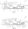
- FIG. 1 illustrates a schematic diagram of a gas turbine machine 10 utilizing the improvements disclosed herein.
- the gas turbine machine 10 includes a first centrifugal compressor 12, an axial compressor 14, a second centrifugal compressor 16, a combustor 18, and a turbine 20.
- a fan 22 includes a nosecone assembly 24, blade members 26, and a fan casing 28. Blade members 26 direct low pressure air to a bypass flow path 30 and to the compressor intake 32, which in turn provides airflow to compressor 12.
- the nosecone assembly 24 generates turbulent airflow, which in turn is directed across the surface of the blade member 26.
- FIG. 2 illustrates a schematic diagram of a three spool turbofan engine 100.
- Turbofan 100 includes a fan 102 coupled to a low pressure turbine (LPT) 112 through shaft 110, a single-stage centrifugal compressor assembly 104 coupled to an intermediate pressure turbine (IPT) 116 through shaft 118.
- Turbofan 100 includes a two-stage axial compressor assembly 106 and a single-stage centrifugal compressor 108 coupled to a high pressure turbine 120 through shafting 122.
- Turbines 120, 116, and 112 are driven by hot gases discharged from a combustion chamber 114.
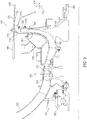
- Figure 3 illustrates a two-stage axial compressor 106 and a single-stage centrifugal compressor 108.
- a thrust bearing 150 provides a structural ground point 152 for rotating components of compressors 106, and 108.
- a transition duct 156 transitions compressed airflow from single-stage centrifugal compressor assembly 104 to two-stage axial compressor assembly 106.
- Structural components 158 and 160 form part of the main backbone of the engine and are structurally isolated from the inner compressor casings 210,212 and 198 of compressors 106 and 108, as will be further illustrated.
- Compressor 108 includes a centrifugal impeller 162 that is attached to rotational shaft 154.
- a shroud 164 is positioned proximate impeller 162 and tip clearance (clearance between impeller 162 and shroud 164) is minimized.
- Structural component 158 is an open girder frame that provides assembly and maintenance access to compressor 108.
- a radial diffuser assembly 166 includes a forward section and a turning duct, and an aft section made up of vaned axial or near axial diffusing passages. Assembly 166 is positioned proximate a discharge location 168 to receive compressed air that is discharged from impeller 162. Radial diffuser 166 includes an elbow or turning duct 170 that redirects airflow from radial diffuser 166 from passing in a radial direction 172 to approximately an axial direction 174. An axial or near-axial diffuser 176 is positioned proximate elbow 170 to receive compressed air from elbow 170 and pass the discharged air to a combustion chamber (such as combustion chamber 114 of Figure 2 ). Axial or near-axial diffuser 176 discharges compressed air in generally axial direction 174.
- carcass or outer case (not shown) distortions can occur due to mechanical loading, thermal loading, component wear, and the like. Because structural components 158 and 160 form part of the main backbone of the engine, they are subject or prone to experience the distortion and motion that can occur in the carcass. In order to minimize the impact of this distortion and reduce the propensity for the distortion to compromise compressor tip clearance, structural isolation is provided by enabling relative motion to occur between structural components 158, 160 and radial diffuser 166.
- elbow 170 of radial diffuser 166 includes an arcuate wall 178 and a second wall 180.
- Arcuate wall 178 includes a wall thickness that diminishes over its length and more particularly over its arced length. That is, arcuate wall 178 includes a first thickness at a first location 182, and a second thickness at a second location 184, and a generally decreasing thickness therebetween. In such fashion, arcuate wall 178 operates to form a cavity or passageway through which compressed air passes, and without leaking or otherwise passing air outside thereof, while also providing a generally non-structural connection between first and second locations 182, 184.
- arcuate wall 178 is a nonstructural Inconel® 718 that is a brazed assembly.
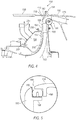
- Near-axial diffuser 176 is also decoupled mechanically from radial diffuser 166 via a seal 186 that, according to the invention, is a w-seal.
- W-seal 186 is further illustrated in Figure 5 and includes a first seal flange 188 attached to wall 180 of radial diffuser 180, and a second seal flange 190 attached to axial diffuser 176.
- W-seal 186 includes a w-shaped and spring-loaded sealing element 192 which, when positioned and compressed between flanges 190 and wall 180, results in sealing compressed air from passing therethrough. Because of the shape of w-shaped element 192, relative motion may occur between wall 180 and diffuser 176 as element 192 compresses, while maintaining a seal and preventing air from passing therethrough.
- radial diffuser 166 provides support for diffuser 176 and for the geometric tailoring of elbow 170
- the radial diffuser 166, shroud 164, and impeller 162 are structurally isolated therefrom.
- the diffuser system including axial diffuser 176 and radial diffuser assembly 166 is joined together as a bolted joint 194 at an outboard interface point, as illustrated.
- Bolted joint 194 is a major structural interface of the gas turbine engine and includes the leg 160 of the outer combustor casing assembly.
- arcuate wall 178 includes first thickness 182 and a lesser second thickness 184, which in one embodiment includes first thickness 182 that is positioned closer to bolted joint 194 than second thickness 184.
- arcuate wall 178 achieves a stiffness level that maintains the vaned radial diffuser section in proper alignment with the impeller discharge, thereby improving impeller tip clearance control.
- a bleed plenum 196 is provided that is formed by a wall material 198 having flanges 200 attached thereto.
- shroud 164 includes a bleed slot 202 positioned therein.
- Bleed slot 202 provides a bleed for air passage therethrough to relieve pressure buildup, such that bleed air can pass 204 through bleed plenum 196.
- wall material in one embodiment is formed by a non-load bearing material that is attached to the radial diffuser and to the shroud.
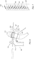
- axial diffuser 176 could include a vaned or de-swirl assembly 300.
- de-swirl assembly 300 includes a de-swirl passage 304 that includes vanes 306.
- vanes 306 include service struts 308 for providing the services described.
- vanes 306 numbering from a count of eighty to one hundred, and eighty-eight in one embodiment and as stated.
- a manifold 310 draws air from, for instance, the centrifugal compressor assembly 104 on the IP spool.
- the relatively cool air from the IP spool passes 312 through one or more of the service struts 308 and passes through a number of buffering passages 322 in order to provide a multi-layer buffer of cool air around bearing compartment 314.
- the buffered and cool air exits 316 and is vented to, typically a low pressure (LP) turbine section.
- LP low pressure
- relatively warm air 318 passing aft of impeller 162 is directed through channels and apertures 320, avoiding the relatively hot compressor air from heating bearing compartment 314.
Landscapes
- Engineering & Computer Science (AREA)
- Mechanical Engineering (AREA)
- General Engineering & Computer Science (AREA)
- Chemical & Material Sciences (AREA)
- Combustion & Propulsion (AREA)
- Physics & Mathematics (AREA)
- Fluid Mechanics (AREA)
- Structures Of Non-Positive Displacement Pumps (AREA)
Claims (13)
- Moteur de turbine à gaz (10, 100) comprenant :un ensemble de compresseur (12, 14, 16, 104, 106, 108) couplé, en rotation, à un arbre (118, 122, 154), l'ensemble de compresseur (12, 14, 16, 104, 106, 108) ayant une roue centrifuge (162) ;un ensemble de diffuseur radial (166) couplé à un flasque (164) de l'ensemble de compresseur (12, 14, 16, 104, 106, 108) et positionné pour recevoir de l'air comprimé de la roue centrifuge (162), l'ensemble de diffuseur radial (166) ayant une première paroi arquée (178) et une seconde paroi (180) ;un autre diffuseur (176) couplé à l'ensemble de diffuseur radial (166) est positionné pour recevoir l'air comprimé de l'ensemble de diffuseur radial (166) ; etun joint d'étanchéité au gaz (186) couplé entre la seconde paroi (180) et une paroi de l'autre diffuseur (176), le joint d'étanchéité au gaz (186) étant configuré pour empêcher le passage de l'air comprimé à travers le joint d'étanchéité (186) tout en permettant le mouvement relatif entre l'ensemble de diffuseur radial (166) et l'autre diffuseur (176) ;caractérisé en ce que :
le joint d'étanchéité au gaz (186) comprend un joint d'étanchéité en forme de w (192) positionné entre le diffuseur radial (166) et l'autre diffuseur (176). - Moteur de turbine à gaz (10, 100) selon la revendication 1, dans lequel la première paroi arquée (178) comprend une épaisseur variable autour de sa partie arquée (170).
- Moteur de turbine à gaz (10, 100) selon la revendication 2, comprenant en outre une structure externe (158, 160) ayant une bride (194) qui est boulonnée au niveau d'un joint boulonné (194) sur une bride de diffuseur (194) qui est fixée au diffuseur radial (166).
- Moteur de turbine à gaz (10, 100) selon la revendication 3, dans lequel l'épaisseur variable comprend un premier emplacement (182) avec une première épaisseur et un second emplacement (184) avec une seconde épaisseur, dans lequel la première épaisseur est supérieure à la seconde épaisseur.
- Moteur de turbine à gaz (10, 100) selon l'une quelconque des revendications précédentes, comprenant en outre :une fente de purge (202) positionnée à l'intérieur du flasque (164) ; etun plénum de purge (196) formé, en partie, par une paroi du flasque (164) et par un matériau de support sans charge (198) qui est fixé au diffuseur radial (166) et au flasque (164), dans lequel l'air de purge qui passe (204) à travers la fente de purge (202) passe dans le plénum de purge (196).
- Moteur de turbine à gaz (10, 100) selon l'une quelconque des revendications précédentes, dans lequel le joint d'étanchéité au gaz (186) comprend :une première bride de joint d'étanchéité (190) fixée sur la paroi de l'autre diffuseur (176) ;une seconde bride de joint d'étanchéité (188) fixée à la seconde paroi (180) du diffuseur radial (166) ; et dans lequel :
le joint d'étanchéité en forme de w (192) est positionné entre la première bride de joint d'étanchéité (190) et la seconde bride de joint d'étanchéité (188). - Moteur de turbine à gaz (10, 100) selon l'une quelconque des revendications précédentes, dans lequel l'autre diffuseur (176) comprend un diffuseur axial ou un diffuseur presque axial.
- Moteur de turbine à gaz (10, 100) selon la revendication 7, dans lequel le diffuseur axial ou le diffuseur presque axial (176) comprend en outre un ensemble à ailettes (300, 306) ayant une ou plusieurs entretoises de service (308) configurées pour faire passer un fluide à travers ces dernières.
- Procédé pour fabriquer un moteur de turbine à gaz (10, 100) comprenant les étapes consistant à :coupler un ensemble de diffuseur radial (166) à un flasque (164) d'un ensemble de compresseur (12, 14, 16, 104, 106, 108), dans lequel l'ensemble de diffuseur radial (166) est positionné pour recevoir de l'air comprimé d'une roue centrifuge (162), et dans lequel l'ensemble de diffuseur radial (166) comprend une première paroi arquée (178) et une seconde paroi (180) ;coupler un second diffuseur (176) à l'ensemble de diffuseur radial (166) pour recevoir l'air comprimé de l'ensemble de diffuseur radial (166) ;coupler un joint d'étanchéité au gaz (186) entre la seconde paroi (180) et une paroi du second diffuseur (176), le joint d'étanchéité au gaz (186) étant configuré pour empêcher l'air comprimé de passer à travers le joint d'étanchéité (186) tout en permettant le mouvement relatif entre l'ensemble de diffuseur radial (166) et le second diffuseur (176) ;fixer une première bride de joint d'étanchéité (190) à la paroi du second diffuseur (176) ;fixer une seconde bride de joint d'étanchéité (188) à la seconde paroi (180) du diffuseur radial (166) ; etpositionner un joint d'étanchéité en forme de w (192) entre les première et seconde brides de joint d'étanchéité (188, 190) afin de former le joint d'étanchéité au gaz (186) couplé entre la seconde paroi (180) et la paroi du second diffuseur (176).
- Procédé selon la revendication 9, comprenant en outre l'étape consistant à former la première paroi arquée (178) de la turbine à gaz (10, 100) ayant une épaisseur variable autour d'une partie arquée (170) de la première paroi arquée (178).
- Procédé selon la revendication 10, comprenant en outre les étapes consistant à :former une structure externe (158, 160) ;fixer une bride de bâti (194) sur la structure externe (158, 160) ;fixer une bride de diffuseur (194) sur le diffuseur radial (166) ; etboulonner la bride de bâti (194) sur la bride de diffuseur (194) .
- Procédé selon la revendication 11, dans lequel l'épaisseur variable comprend un premier emplacement (182) avec une première épaisseur et un second emplacement (184) avec une seconde épaisseur, dans lequel la première épaisseur est supérieure à la seconde épaisseur, et dans lequel le premier emplacement (182) est plus à proximité d'un joint boulonné (194) que le second emplacement (184).
- Procédé selon l'une quelconque des revendications 9 à 12, le procédé comprenant en outre les étapes consistant à :former une fente de purge (202) à l'intérieur du flasque (164) ;former un plénum de purge (196) avec les étapes consistant à :fixer un matériau de support sans charge (198) au diffuseur radial (166) ; etfixer le matériau de support sans charge (198) au flasque (164) ;dans lequel l'air de purge qui passe (204) par la fente de purge (202) passe dans le plénum de purge (198).
Applications Claiming Priority (2)
| Application Number | Priority Date | Filing Date | Title |
|---|---|---|---|
| US201361775381P | 2013-03-08 | 2013-03-08 | |
| PCT/US2013/073216 WO2014137430A1 (fr) | 2013-03-08 | 2013-12-05 | Compresseur centrifuge de moteur à turbine à gaz doté d'un joint entre deux parties de diffuseur |
Publications (2)
| Publication Number | Publication Date |
|---|---|
| EP2964960A1 EP2964960A1 (fr) | 2016-01-13 |
| EP2964960B1 true EP2964960B1 (fr) | 2019-06-12 |
Family
ID=49780437
Family Applications (1)
| Application Number | Title | Priority Date | Filing Date |
|---|---|---|---|
| EP13808423.1A Not-in-force EP2964960B1 (fr) | 2013-03-08 | 2013-12-05 | Compresseur centrifuge de moteur à turbine à gaz avec joint d'étanchéité entre deux parties de diffuseur |
Country Status (3)
| Country | Link |
|---|---|
| US (1) | US9726032B2 (fr) |
| EP (1) | EP2964960B1 (fr) |
| WO (1) | WO2014137430A1 (fr) |
Families Citing this family (18)
| Publication number | Priority date | Publication date | Assignee | Title |
|---|---|---|---|---|
| US10344623B2 (en) * | 2014-12-16 | 2019-07-09 | United Technologies Corporation | Pre-diffuser strut for gas turbine engine |
| DE102015219556A1 (de) | 2015-10-08 | 2017-04-13 | Rolls-Royce Deutschland Ltd & Co Kg | Diffusor für Radialverdichter, Radialverdichter und Turbomaschine mit Radialverdichter |
| US10544693B2 (en) | 2016-06-15 | 2020-01-28 | Honeywell International Inc. | Service routing configuration for a gas turbine engine diffuser system |
| US20180017078A1 (en) * | 2016-07-12 | 2018-01-18 | Rolls-Royce Corporation | Static hub transition duct |
| US20180135525A1 (en) * | 2016-11-14 | 2018-05-17 | Pratt & Whitney Canada Corp. | Gas turbine engine tangential orifice bleed configuration |
| US11174786B2 (en) * | 2016-11-15 | 2021-11-16 | General Electric Company | Monolithic superstructure for load path optimization |
| US10605253B2 (en) | 2017-11-28 | 2020-03-31 | Honeywell International Inc. | Compressor with offset diffuser for integral bleed |
| US11603852B2 (en) * | 2018-01-19 | 2023-03-14 | General Electric Company | Compressor bleed port structure |
| US11098650B2 (en) * | 2018-08-10 | 2021-08-24 | Pratt & Whitney Canada Corp. | Compressor diffuser with diffuser pipes having aero-dampers |
| US10989219B2 (en) | 2019-02-04 | 2021-04-27 | Honeywell International Inc. | Diffuser assemblies for compression systems |
| US11098730B2 (en) | 2019-04-12 | 2021-08-24 | Rolls-Royce Corporation | Deswirler assembly for a centrifugal compressor |
| US11255213B2 (en) * | 2019-07-15 | 2022-02-22 | Pratt & Whitney Canada Corp. | Shroud assembly for centrifugal compressor and method |
| US11441516B2 (en) | 2020-07-14 | 2022-09-13 | Rolls-Royce North American Technologies Inc. | Centrifugal compressor assembly for a gas turbine engine with deswirler having sealing features |
| US11286952B2 (en) | 2020-07-14 | 2022-03-29 | Rolls-Royce Corporation | Diffusion system configured for use with centrifugal compressor |
| US11578654B2 (en) | 2020-07-29 | 2023-02-14 | Rolls-Royce North American Technologies Inc. | Centrifical compressor assembly for a gas turbine engine |
| US11578869B2 (en) * | 2021-05-20 | 2023-02-14 | General Electric Company | Active boundary layer control in diffuser |
| CN114704386B (zh) * | 2022-04-24 | 2024-03-19 | 中国航发沈阳发动机研究所 | 一种高超飞行器涡轮发动机支点封严方法及结构 |
| US11959401B1 (en) | 2023-03-24 | 2024-04-16 | Honeywell International Inc. | Deswirl system for gas turbine engine |
Citations (1)
| Publication number | Priority date | Publication date | Assignee | Title |
|---|---|---|---|---|
| WO1996019640A1 (fr) * | 1994-12-21 | 1996-06-27 | Alliedsignal Inc. | Assemblage de confinement de moyeu de compresseur centrifuge |
Family Cites Families (16)
| Publication number | Priority date | Publication date | Assignee | Title |
|---|---|---|---|---|
| US3832089A (en) | 1972-08-28 | 1974-08-27 | Avco Corp | Turbomachinery and method of manufacturing diffusers therefor |
| US6279322B1 (en) * | 1999-09-07 | 2001-08-28 | General Electric Company | Deswirler system for centrifugal compressor |
| US6488469B1 (en) | 2000-10-06 | 2002-12-03 | Pratt & Whitney Canada Corp. | Mixed flow and centrifugal compressor for gas turbine engine |
| US6589015B1 (en) | 2002-05-08 | 2003-07-08 | Pratt & Whitney Canada Corp. | Discrete passage diffuser |
| DE602004014154D1 (de) | 2003-07-29 | 2008-07-10 | Pratt & Whitney Canada | Turbofan-Triebwerksgehäuse, Turbofantriebwerk und entsprechendes Verfahren |
| US7025566B2 (en) * | 2003-11-04 | 2006-04-11 | Pratt & Whitney Canada Corp. | Hybrid vane island diffuser |
| FR2868119B1 (fr) * | 2004-03-26 | 2006-06-16 | Snecma Moteurs Sa | Joint d'etancheite entre les carters interieurs et exterieurs d'une section de turboreacteur |
| US7442006B2 (en) * | 2005-08-15 | 2008-10-28 | Honeywell International Inc. | Integral diffuser and deswirler with continuous flow path deflected at assembly |
| FR2904038A1 (fr) | 2006-07-19 | 2008-01-25 | Snecma Sa | Systeme de refroidissement de la face aval d'un rouet de compresseur centrifuge |
| US7717672B2 (en) | 2006-08-29 | 2010-05-18 | Honeywell International Inc. | Radial vaned diffusion system with integral service routings |
| US7908869B2 (en) | 2006-09-18 | 2011-03-22 | Pratt & Whitney Canada Corp. | Thermal and external load isolating impeller shroud |
| US7798777B2 (en) | 2006-12-15 | 2010-09-21 | General Electric Company | Engine compressor assembly and method of operating the same |
| US8220268B2 (en) | 2007-11-28 | 2012-07-17 | Caterpillar Inc. | Turbine engine having fuel-cooled air intercooling |
| FR2927951B1 (fr) * | 2008-02-27 | 2011-08-19 | Snecma | Ensemble diffuseur-redresseur pour une turbomachine |
| FR2932227B1 (fr) | 2008-06-09 | 2011-07-01 | Snecma | Turboreacteur double flux |
| US8459941B2 (en) | 2009-06-15 | 2013-06-11 | General Electric Company | Mechanical joint for a gas turbine engine |
-
2013
- 2013-12-05 EP EP13808423.1A patent/EP2964960B1/fr not_active Not-in-force
- 2013-12-05 WO PCT/US2013/073216 patent/WO2014137430A1/fr not_active Ceased
- 2013-12-20 US US14/137,987 patent/US9726032B2/en active Active
Patent Citations (1)
| Publication number | Priority date | Publication date | Assignee | Title |
|---|---|---|---|---|
| WO1996019640A1 (fr) * | 1994-12-21 | 1996-06-27 | Alliedsignal Inc. | Assemblage de confinement de moyeu de compresseur centrifuge |
Also Published As
| Publication number | Publication date |
|---|---|
| WO2014137430A1 (fr) | 2014-09-12 |
| US20140255181A1 (en) | 2014-09-11 |
| EP2964960A1 (fr) | 2016-01-13 |
| US9726032B2 (en) | 2017-08-08 |
Similar Documents
| Publication | Publication Date | Title |
|---|---|---|
| EP2964960B1 (fr) | Compresseur centrifuge de moteur à turbine à gaz avec joint d'étanchéité entre deux parties de diffuseur | |
| US11021990B2 (en) | Shroud sealing for a gas turbine engine | |
| CN109519229B (zh) | 交错燃气涡轮发动机及操作主动间隙控制系统的方法 | |
| US10301960B2 (en) | Shroud assembly for gas turbine engine | |
| EP2961991B1 (fr) | Système d'hélice de moteur de turbine à gaz pour compresseur de pression intermédiaire (ip) | |
| US9976485B2 (en) | Gas turbine engine buffer cooling system | |
| US10370986B2 (en) | Nozzle and nozzle assembly for gas turbine engine | |
| EP2820272B1 (fr) | Système tampon de refroidissement fournissant un refroidissement d'architecture de moteur à turbine à gaz | |
| EP3095958B1 (fr) | Système de protection thermique d'une partie d'un ensemble d'anneau de cerclage de turbine à gaz | |
| EP4001596B1 (fr) | Moteur à turbine à gaz | |
| US9435259B2 (en) | Gas turbine engine cooling system | |
| US20160273382A1 (en) | System for cooling a turbine shroud | |
| CN109026167B (zh) | 包括冷却和涡轮间隙控制系统及其空气供给风戽的涡轮机 | |
| US10161266B2 (en) | Nozzle and nozzle assembly for gas turbine engine | |
| EP3287605B1 (fr) | Joint de bordure pour moteur à turbine à gaz | |
| EP3524795B1 (fr) | Compresseur axial comportant un compresseur centrifuge inter-étages | |
| US10801365B2 (en) | Turbine engine and components for use therein | |
| EP3699400B1 (fr) | Système de moteur à turbine à gaz avec joint coulissant léger à faible blocage | |
| US20250172095A1 (en) | Turbomachine with axial thrust management | |
| EP3650675B1 (fr) | Système d'échangeur thermique interne pour refroidir des composants de moteur de turbine à gaz |
Legal Events
| Date | Code | Title | Description |
|---|---|---|---|
| PUAI | Public reference made under article 153(3) epc to a published international application that has entered the european phase |
Free format text: ORIGINAL CODE: 0009012 |
|
| 17P | Request for examination filed |
Effective date: 20151006 |
|
| AK | Designated contracting states |
Kind code of ref document: A1 Designated state(s): AL AT BE BG CH CY CZ DE DK EE ES FI FR GB GR HR HU IE IS IT LI LT LU LV MC MK MT NL NO PL PT RO RS SE SI SK SM TR |
|
| AX | Request for extension of the european patent |
Extension state: BA ME |
|
| DAX | Request for extension of the european patent (deleted) | ||
| GRAP | Despatch of communication of intention to grant a patent |
Free format text: ORIGINAL CODE: EPIDOSNIGR1 |
|
| STAA | Information on the status of an ep patent application or granted ep patent |
Free format text: STATUS: GRANT OF PATENT IS INTENDED |
|
| INTG | Intention to grant announced |
Effective date: 20190122 |
|
| GRAS | Grant fee paid |
Free format text: ORIGINAL CODE: EPIDOSNIGR3 |
|
| GRAA | (expected) grant |
Free format text: ORIGINAL CODE: 0009210 |
|
| STAA | Information on the status of an ep patent application or granted ep patent |
Free format text: STATUS: THE PATENT HAS BEEN GRANTED |
|
| AK | Designated contracting states |
Kind code of ref document: B1 Designated state(s): AL AT BE BG CH CY CZ DE DK EE ES FI FR GB GR HR HU IE IS IT LI LT LU LV MC MK MT NL NO PL PT RO RS SE SI SK SM TR |
|
| REG | Reference to a national code |
Ref country code: GB Ref legal event code: FG4D |
|
| REG | Reference to a national code |
Ref country code: CH Ref legal event code: EP |
|
| REG | Reference to a national code |
Ref country code: AT Ref legal event code: REF Ref document number: 1142911 Country of ref document: AT Kind code of ref document: T Effective date: 20190615 |
|
| REG | Reference to a national code |
Ref country code: IE Ref legal event code: FG4D |
|
| REG | Reference to a national code |
Ref country code: DE Ref legal event code: R096 Ref document number: 602013056596 Country of ref document: DE |
|
| REG | Reference to a national code |
Ref country code: NL Ref legal event code: MP Effective date: 20190612 |
|
| REG | Reference to a national code |
Ref country code: LT Ref legal event code: MG4D |
|
| PG25 | Lapsed in a contracting state [announced via postgrant information from national office to epo] |
Ref country code: SE Free format text: LAPSE BECAUSE OF FAILURE TO SUBMIT A TRANSLATION OF THE DESCRIPTION OR TO PAY THE FEE WITHIN THE PRESCRIBED TIME-LIMIT Effective date: 20190612 Ref country code: HR Free format text: LAPSE BECAUSE OF FAILURE TO SUBMIT A TRANSLATION OF THE DESCRIPTION OR TO PAY THE FEE WITHIN THE PRESCRIBED TIME-LIMIT Effective date: 20190612 Ref country code: AL Free format text: LAPSE BECAUSE OF FAILURE TO SUBMIT A TRANSLATION OF THE DESCRIPTION OR TO PAY THE FEE WITHIN THE PRESCRIBED TIME-LIMIT Effective date: 20190612 Ref country code: FI Free format text: LAPSE BECAUSE OF FAILURE TO SUBMIT A TRANSLATION OF THE DESCRIPTION OR TO PAY THE FEE WITHIN THE PRESCRIBED TIME-LIMIT Effective date: 20190612 Ref country code: NO Free format text: LAPSE BECAUSE OF FAILURE TO SUBMIT A TRANSLATION OF THE DESCRIPTION OR TO PAY THE FEE WITHIN THE PRESCRIBED TIME-LIMIT Effective date: 20190912 Ref country code: LT Free format text: LAPSE BECAUSE OF FAILURE TO SUBMIT A TRANSLATION OF THE DESCRIPTION OR TO PAY THE FEE WITHIN THE PRESCRIBED TIME-LIMIT Effective date: 20190612 |
|
| PG25 | Lapsed in a contracting state [announced via postgrant information from national office to epo] |
Ref country code: GR Free format text: LAPSE BECAUSE OF FAILURE TO SUBMIT A TRANSLATION OF THE DESCRIPTION OR TO PAY THE FEE WITHIN THE PRESCRIBED TIME-LIMIT Effective date: 20190913 Ref country code: BG Free format text: LAPSE BECAUSE OF FAILURE TO SUBMIT A TRANSLATION OF THE DESCRIPTION OR TO PAY THE FEE WITHIN THE PRESCRIBED TIME-LIMIT Effective date: 20190912 Ref country code: RS Free format text: LAPSE BECAUSE OF FAILURE TO SUBMIT A TRANSLATION OF THE DESCRIPTION OR TO PAY THE FEE WITHIN THE PRESCRIBED TIME-LIMIT Effective date: 20190612 Ref country code: LV Free format text: LAPSE BECAUSE OF FAILURE TO SUBMIT A TRANSLATION OF THE DESCRIPTION OR TO PAY THE FEE WITHIN THE PRESCRIBED TIME-LIMIT Effective date: 20190612 |
|
| REG | Reference to a national code |
Ref country code: AT Ref legal event code: MK05 Ref document number: 1142911 Country of ref document: AT Kind code of ref document: T Effective date: 20190612 |
|
| PG25 | Lapsed in a contracting state [announced via postgrant information from national office to epo] |
Ref country code: NL Free format text: LAPSE BECAUSE OF FAILURE TO SUBMIT A TRANSLATION OF THE DESCRIPTION OR TO PAY THE FEE WITHIN THE PRESCRIBED TIME-LIMIT Effective date: 20190612 Ref country code: EE Free format text: LAPSE BECAUSE OF FAILURE TO SUBMIT A TRANSLATION OF THE DESCRIPTION OR TO PAY THE FEE WITHIN THE PRESCRIBED TIME-LIMIT Effective date: 20190612 Ref country code: AT Free format text: LAPSE BECAUSE OF FAILURE TO SUBMIT A TRANSLATION OF THE DESCRIPTION OR TO PAY THE FEE WITHIN THE PRESCRIBED TIME-LIMIT Effective date: 20190612 Ref country code: RO Free format text: LAPSE BECAUSE OF FAILURE TO SUBMIT A TRANSLATION OF THE DESCRIPTION OR TO PAY THE FEE WITHIN THE PRESCRIBED TIME-LIMIT Effective date: 20190612 Ref country code: CZ Free format text: LAPSE BECAUSE OF FAILURE TO SUBMIT A TRANSLATION OF THE DESCRIPTION OR TO PAY THE FEE WITHIN THE PRESCRIBED TIME-LIMIT Effective date: 20190612 Ref country code: SK Free format text: LAPSE BECAUSE OF FAILURE TO SUBMIT A TRANSLATION OF THE DESCRIPTION OR TO PAY THE FEE WITHIN THE PRESCRIBED TIME-LIMIT Effective date: 20190612 Ref country code: PT Free format text: LAPSE BECAUSE OF FAILURE TO SUBMIT A TRANSLATION OF THE DESCRIPTION OR TO PAY THE FEE WITHIN THE PRESCRIBED TIME-LIMIT Effective date: 20191014 |
|
| RAP2 | Party data changed (patent owner data changed or rights of a patent transferred) |
Owner name: ROLLS-ROYCE NORTH AMERICAN TECHNOLOGIES, INC. Owner name: ROLLS-ROYCE PLC |
|
| PG25 | Lapsed in a contracting state [announced via postgrant information from national office to epo] |
Ref country code: IS Free format text: LAPSE BECAUSE OF FAILURE TO SUBMIT A TRANSLATION OF THE DESCRIPTION OR TO PAY THE FEE WITHIN THE PRESCRIBED TIME-LIMIT Effective date: 20191012 Ref country code: SM Free format text: LAPSE BECAUSE OF FAILURE TO SUBMIT A TRANSLATION OF THE DESCRIPTION OR TO PAY THE FEE WITHIN THE PRESCRIBED TIME-LIMIT Effective date: 20190612 Ref country code: IT Free format text: LAPSE BECAUSE OF FAILURE TO SUBMIT A TRANSLATION OF THE DESCRIPTION OR TO PAY THE FEE WITHIN THE PRESCRIBED TIME-LIMIT Effective date: 20190612 Ref country code: ES Free format text: LAPSE BECAUSE OF FAILURE TO SUBMIT A TRANSLATION OF THE DESCRIPTION OR TO PAY THE FEE WITHIN THE PRESCRIBED TIME-LIMIT Effective date: 20190612 |
|
| PGFP | Annual fee paid to national office [announced via postgrant information from national office to epo] |
Ref country code: FR Payment date: 20191226 Year of fee payment: 7 |
|
| REG | Reference to a national code |
Ref country code: DE Ref legal event code: R097 Ref document number: 602013056596 Country of ref document: DE |
|
| PG25 | Lapsed in a contracting state [announced via postgrant information from national office to epo] |
Ref country code: TR Free format text: LAPSE BECAUSE OF FAILURE TO SUBMIT A TRANSLATION OF THE DESCRIPTION OR TO PAY THE FEE WITHIN THE PRESCRIBED TIME-LIMIT Effective date: 20190612 |
|
| PLBE | No opposition filed within time limit |
Free format text: ORIGINAL CODE: 0009261 |
|
| STAA | Information on the status of an ep patent application or granted ep patent |
Free format text: STATUS: NO OPPOSITION FILED WITHIN TIME LIMIT |
|
| PG25 | Lapsed in a contracting state [announced via postgrant information from national office to epo] |
Ref country code: DK Free format text: LAPSE BECAUSE OF FAILURE TO SUBMIT A TRANSLATION OF THE DESCRIPTION OR TO PAY THE FEE WITHIN THE PRESCRIBED TIME-LIMIT Effective date: 20190612 Ref country code: PL Free format text: LAPSE BECAUSE OF FAILURE TO SUBMIT A TRANSLATION OF THE DESCRIPTION OR TO PAY THE FEE WITHIN THE PRESCRIBED TIME-LIMIT Effective date: 20190612 |
|
| PGFP | Annual fee paid to national office [announced via postgrant information from national office to epo] |
Ref country code: DE Payment date: 20191231 Year of fee payment: 7 |
|
| 26N | No opposition filed |
Effective date: 20200313 |
|
| PG25 | Lapsed in a contracting state [announced via postgrant information from national office to epo] |
Ref country code: IS Free format text: LAPSE BECAUSE OF FAILURE TO SUBMIT A TRANSLATION OF THE DESCRIPTION OR TO PAY THE FEE WITHIN THE PRESCRIBED TIME-LIMIT Effective date: 20200224 Ref country code: SI Free format text: LAPSE BECAUSE OF FAILURE TO SUBMIT A TRANSLATION OF THE DESCRIPTION OR TO PAY THE FEE WITHIN THE PRESCRIBED TIME-LIMIT Effective date: 20190612 |
|
| PG2D | Information on lapse in contracting state deleted |
Ref country code: IS |
|
| REG | Reference to a national code |
Ref country code: CH Ref legal event code: PL |
|
| REG | Reference to a national code |
Ref country code: BE Ref legal event code: MM Effective date: 20191231 |
|
| PG25 | Lapsed in a contracting state [announced via postgrant information from national office to epo] |
Ref country code: MC Free format text: LAPSE BECAUSE OF FAILURE TO SUBMIT A TRANSLATION OF THE DESCRIPTION OR TO PAY THE FEE WITHIN THE PRESCRIBED TIME-LIMIT Effective date: 20190612 |
|
| GBPC | Gb: european patent ceased through non-payment of renewal fee |
Effective date: 20191205 |
|
| PG25 | Lapsed in a contracting state [announced via postgrant information from national office to epo] |
Ref country code: IE Free format text: LAPSE BECAUSE OF NON-PAYMENT OF DUE FEES Effective date: 20191205 Ref country code: GB Free format text: LAPSE BECAUSE OF NON-PAYMENT OF DUE FEES Effective date: 20191205 Ref country code: LU Free format text: LAPSE BECAUSE OF NON-PAYMENT OF DUE FEES Effective date: 20191205 |
|
| PG25 | Lapsed in a contracting state [announced via postgrant information from national office to epo] |
Ref country code: LI Free format text: LAPSE BECAUSE OF NON-PAYMENT OF DUE FEES Effective date: 20191231 Ref country code: CH Free format text: LAPSE BECAUSE OF NON-PAYMENT OF DUE FEES Effective date: 20191231 Ref country code: BE Free format text: LAPSE BECAUSE OF NON-PAYMENT OF DUE FEES Effective date: 20191231 |
|
| PG25 | Lapsed in a contracting state [announced via postgrant information from national office to epo] |
Ref country code: CY Free format text: LAPSE BECAUSE OF FAILURE TO SUBMIT A TRANSLATION OF THE DESCRIPTION OR TO PAY THE FEE WITHIN THE PRESCRIBED TIME-LIMIT Effective date: 20190612 |
|
| REG | Reference to a national code |
Ref country code: DE Ref legal event code: R119 Ref document number: 602013056596 Country of ref document: DE |
|
| PG25 | Lapsed in a contracting state [announced via postgrant information from national office to epo] |
Ref country code: MT Free format text: LAPSE BECAUSE OF FAILURE TO SUBMIT A TRANSLATION OF THE DESCRIPTION OR TO PAY THE FEE WITHIN THE PRESCRIBED TIME-LIMIT Effective date: 20190612 Ref country code: HU Free format text: LAPSE BECAUSE OF FAILURE TO SUBMIT A TRANSLATION OF THE DESCRIPTION OR TO PAY THE FEE WITHIN THE PRESCRIBED TIME-LIMIT; INVALID AB INITIO Effective date: 20131205 |
|
| PG25 | Lapsed in a contracting state [announced via postgrant information from national office to epo] |
Ref country code: FR Free format text: LAPSE BECAUSE OF NON-PAYMENT OF DUE FEES Effective date: 20201231 |
|
| PG25 | Lapsed in a contracting state [announced via postgrant information from national office to epo] |
Ref country code: DE Free format text: LAPSE BECAUSE OF NON-PAYMENT OF DUE FEES Effective date: 20210701 |
|
| PG25 | Lapsed in a contracting state [announced via postgrant information from national office to epo] |
Ref country code: MK Free format text: LAPSE BECAUSE OF FAILURE TO SUBMIT A TRANSLATION OF THE DESCRIPTION OR TO PAY THE FEE WITHIN THE PRESCRIBED TIME-LIMIT Effective date: 20190612 |
|
| P01 | Opt-out of the competence of the unified patent court (upc) registered |
Effective date: 20230528 |