EP2965029B2 - Installation de séparation d'air, procédé de récupération d'un produit contenant de l'argon et procédé pour créer une installation de séparation d'air - Google Patents
Installation de séparation d'air, procédé de récupération d'un produit contenant de l'argon et procédé pour créer une installation de séparation d'air Download PDFInfo
- Publication number
- EP2965029B2 EP2965029B2 EP14716232.5A EP14716232A EP2965029B2 EP 2965029 B2 EP2965029 B2 EP 2965029B2 EP 14716232 A EP14716232 A EP 14716232A EP 2965029 B2 EP2965029 B2 EP 2965029B2
- Authority
- EP
- European Patent Office
- Prior art keywords
- column
- low
- pressure column
- section
- argon
- Prior art date
- Legal status (The legal status is an assumption and is not a legal conclusion. Google has not performed a legal analysis and makes no representation as to the accuracy of the status listed.)
- Active
Links
Images
Classifications
-
- F—MECHANICAL ENGINEERING; LIGHTING; HEATING; WEAPONS; BLASTING
- F25—REFRIGERATION OR COOLING; COMBINED HEATING AND REFRIGERATION SYSTEMS; HEAT PUMP SYSTEMS; MANUFACTURE OR STORAGE OF ICE; LIQUEFACTION SOLIDIFICATION OF GASES
- F25J—LIQUEFACTION, SOLIDIFICATION OR SEPARATION OF GASES OR GASEOUS OR LIQUEFIED GASEOUS MIXTURES BY PRESSURE AND COLD TREATMENT OR BY BRINGING THEM INTO THE SUPERCRITICAL STATE
- F25J3/00—Processes or apparatus for separating the constituents of gaseous or liquefied gaseous mixtures involving the use of liquefaction or solidification
- F25J3/02—Processes or apparatus for separating the constituents of gaseous or liquefied gaseous mixtures involving the use of liquefaction or solidification by rectification, i.e. by continuous interchange of heat and material between a vapour stream and a liquid stream
- F25J3/0228—Processes or apparatus for separating the constituents of gaseous or liquefied gaseous mixtures involving the use of liquefaction or solidification by rectification, i.e. by continuous interchange of heat and material between a vapour stream and a liquid stream characterised by the separated product stream
- F25J3/028—Processes or apparatus for separating the constituents of gaseous or liquefied gaseous mixtures involving the use of liquefaction or solidification by rectification, i.e. by continuous interchange of heat and material between a vapour stream and a liquid stream characterised by the separated product stream separation of noble gases
- F25J3/0285—Processes or apparatus for separating the constituents of gaseous or liquefied gaseous mixtures involving the use of liquefaction or solidification by rectification, i.e. by continuous interchange of heat and material between a vapour stream and a liquid stream characterised by the separated product stream separation of noble gases of argon
-
- F—MECHANICAL ENGINEERING; LIGHTING; HEATING; WEAPONS; BLASTING
- F25—REFRIGERATION OR COOLING; COMBINED HEATING AND REFRIGERATION SYSTEMS; HEAT PUMP SYSTEMS; MANUFACTURE OR STORAGE OF ICE; LIQUEFACTION SOLIDIFICATION OF GASES
- F25J—LIQUEFACTION, SOLIDIFICATION OR SEPARATION OF GASES OR GASEOUS OR LIQUEFIED GASEOUS MIXTURES BY PRESSURE AND COLD TREATMENT OR BY BRINGING THEM INTO THE SUPERCRITICAL STATE
- F25J3/00—Processes or apparatus for separating the constituents of gaseous or liquefied gaseous mixtures involving the use of liquefaction or solidification
- F25J3/02—Processes or apparatus for separating the constituents of gaseous or liquefied gaseous mixtures involving the use of liquefaction or solidification by rectification, i.e. by continuous interchange of heat and material between a vapour stream and a liquid stream
- F25J3/04—Processes or apparatus for separating the constituents of gaseous or liquefied gaseous mixtures involving the use of liquefaction or solidification by rectification, i.e. by continuous interchange of heat and material between a vapour stream and a liquid stream for air
- F25J3/04006—Providing pressurised feed air or process streams within or from the air fractionation unit
- F25J3/04048—Providing pressurised feed air or process streams within or from the air fractionation unit by compression of cold gaseous streams, e.g. intermediate or oxygen enriched (waste) streams
-
- F—MECHANICAL ENGINEERING; LIGHTING; HEATING; WEAPONS; BLASTING
- F25—REFRIGERATION OR COOLING; COMBINED HEATING AND REFRIGERATION SYSTEMS; HEAT PUMP SYSTEMS; MANUFACTURE OR STORAGE OF ICE; LIQUEFACTION SOLIDIFICATION OF GASES
- F25J—LIQUEFACTION, SOLIDIFICATION OR SEPARATION OF GASES OR GASEOUS OR LIQUEFIED GASEOUS MIXTURES BY PRESSURE AND COLD TREATMENT OR BY BRINGING THEM INTO THE SUPERCRITICAL STATE
- F25J3/00—Processes or apparatus for separating the constituents of gaseous or liquefied gaseous mixtures involving the use of liquefaction or solidification
- F25J3/02—Processes or apparatus for separating the constituents of gaseous or liquefied gaseous mixtures involving the use of liquefaction or solidification by rectification, i.e. by continuous interchange of heat and material between a vapour stream and a liquid stream
- F25J3/04—Processes or apparatus for separating the constituents of gaseous or liquefied gaseous mixtures involving the use of liquefaction or solidification by rectification, i.e. by continuous interchange of heat and material between a vapour stream and a liquid stream for air
- F25J3/04006—Providing pressurised feed air or process streams within or from the air fractionation unit
- F25J3/04078—Providing pressurised feed air or process streams within or from the air fractionation unit providing pressurized products by liquid compression and vaporisation with cold recovery, i.e. so-called internal compression
- F25J3/0409—Providing pressurised feed air or process streams within or from the air fractionation unit providing pressurized products by liquid compression and vaporisation with cold recovery, i.e. so-called internal compression of oxygen
-
- F—MECHANICAL ENGINEERING; LIGHTING; HEATING; WEAPONS; BLASTING
- F25—REFRIGERATION OR COOLING; COMBINED HEATING AND REFRIGERATION SYSTEMS; HEAT PUMP SYSTEMS; MANUFACTURE OR STORAGE OF ICE; LIQUEFACTION SOLIDIFICATION OF GASES
- F25J—LIQUEFACTION, SOLIDIFICATION OR SEPARATION OF GASES OR GASEOUS OR LIQUEFIED GASEOUS MIXTURES BY PRESSURE AND COLD TREATMENT OR BY BRINGING THEM INTO THE SUPERCRITICAL STATE
- F25J3/00—Processes or apparatus for separating the constituents of gaseous or liquefied gaseous mixtures involving the use of liquefaction or solidification
- F25J3/02—Processes or apparatus for separating the constituents of gaseous or liquefied gaseous mixtures involving the use of liquefaction or solidification by rectification, i.e. by continuous interchange of heat and material between a vapour stream and a liquid stream
- F25J3/04—Processes or apparatus for separating the constituents of gaseous or liquefied gaseous mixtures involving the use of liquefaction or solidification by rectification, i.e. by continuous interchange of heat and material between a vapour stream and a liquid stream for air
- F25J3/04406—Processes or apparatus for separating the constituents of gaseous or liquefied gaseous mixtures involving the use of liquefaction or solidification by rectification, i.e. by continuous interchange of heat and material between a vapour stream and a liquid stream for air using a dual pressure main column system
- F25J3/04412—Processes or apparatus for separating the constituents of gaseous or liquefied gaseous mixtures involving the use of liquefaction or solidification by rectification, i.e. by continuous interchange of heat and material between a vapour stream and a liquid stream for air using a dual pressure main column system in a classical double column flowsheet, i.e. with thermal coupling by a main reboiler-condenser in the bottom of low pressure respectively top of high pressure column
-
- F—MECHANICAL ENGINEERING; LIGHTING; HEATING; WEAPONS; BLASTING
- F25—REFRIGERATION OR COOLING; COMBINED HEATING AND REFRIGERATION SYSTEMS; HEAT PUMP SYSTEMS; MANUFACTURE OR STORAGE OF ICE; LIQUEFACTION SOLIDIFICATION OF GASES
- F25J—LIQUEFACTION, SOLIDIFICATION OR SEPARATION OF GASES OR GASEOUS OR LIQUEFIED GASEOUS MIXTURES BY PRESSURE AND COLD TREATMENT OR BY BRINGING THEM INTO THE SUPERCRITICAL STATE
- F25J3/00—Processes or apparatus for separating the constituents of gaseous or liquefied gaseous mixtures involving the use of liquefaction or solidification
- F25J3/02—Processes or apparatus for separating the constituents of gaseous or liquefied gaseous mixtures involving the use of liquefaction or solidification by rectification, i.e. by continuous interchange of heat and material between a vapour stream and a liquid stream
- F25J3/04—Processes or apparatus for separating the constituents of gaseous or liquefied gaseous mixtures involving the use of liquefaction or solidification by rectification, i.e. by continuous interchange of heat and material between a vapour stream and a liquid stream for air
- F25J3/04406—Processes or apparatus for separating the constituents of gaseous or liquefied gaseous mixtures involving the use of liquefaction or solidification by rectification, i.e. by continuous interchange of heat and material between a vapour stream and a liquid stream for air using a dual pressure main column system
- F25J3/04424—Processes or apparatus for separating the constituents of gaseous or liquefied gaseous mixtures involving the use of liquefaction or solidification by rectification, i.e. by continuous interchange of heat and material between a vapour stream and a liquid stream for air using a dual pressure main column system without thermally coupled high and low pressure columns, i.e. a so-called split columns
-
- F—MECHANICAL ENGINEERING; LIGHTING; HEATING; WEAPONS; BLASTING
- F25—REFRIGERATION OR COOLING; COMBINED HEATING AND REFRIGERATION SYSTEMS; HEAT PUMP SYSTEMS; MANUFACTURE OR STORAGE OF ICE; LIQUEFACTION SOLIDIFICATION OF GASES
- F25J—LIQUEFACTION, SOLIDIFICATION OR SEPARATION OF GASES OR GASEOUS OR LIQUEFIED GASEOUS MIXTURES BY PRESSURE AND COLD TREATMENT OR BY BRINGING THEM INTO THE SUPERCRITICAL STATE
- F25J3/00—Processes or apparatus for separating the constituents of gaseous or liquefied gaseous mixtures involving the use of liquefaction or solidification
- F25J3/02—Processes or apparatus for separating the constituents of gaseous or liquefied gaseous mixtures involving the use of liquefaction or solidification by rectification, i.e. by continuous interchange of heat and material between a vapour stream and a liquid stream
- F25J3/04—Processes or apparatus for separating the constituents of gaseous or liquefied gaseous mixtures involving the use of liquefaction or solidification by rectification, i.e. by continuous interchange of heat and material between a vapour stream and a liquid stream for air
- F25J3/04624—Processes or apparatus for separating the constituents of gaseous or liquefied gaseous mixtures involving the use of liquefaction or solidification by rectification, i.e. by continuous interchange of heat and material between a vapour stream and a liquid stream for air using integrated mass and heat exchange, so-called non-adiabatic rectification, e.g. dephlegmator, reflux exchanger
-
- F—MECHANICAL ENGINEERING; LIGHTING; HEATING; WEAPONS; BLASTING
- F25—REFRIGERATION OR COOLING; COMBINED HEATING AND REFRIGERATION SYSTEMS; HEAT PUMP SYSTEMS; MANUFACTURE OR STORAGE OF ICE; LIQUEFACTION SOLIDIFICATION OF GASES
- F25J—LIQUEFACTION, SOLIDIFICATION OR SEPARATION OF GASES OR GASEOUS OR LIQUEFIED GASEOUS MIXTURES BY PRESSURE AND COLD TREATMENT OR BY BRINGING THEM INTO THE SUPERCRITICAL STATE
- F25J3/00—Processes or apparatus for separating the constituents of gaseous or liquefied gaseous mixtures involving the use of liquefaction or solidification
- F25J3/02—Processes or apparatus for separating the constituents of gaseous or liquefied gaseous mixtures involving the use of liquefaction or solidification by rectification, i.e. by continuous interchange of heat and material between a vapour stream and a liquid stream
- F25J3/04—Processes or apparatus for separating the constituents of gaseous or liquefied gaseous mixtures involving the use of liquefaction or solidification by rectification, i.e. by continuous interchange of heat and material between a vapour stream and a liquid stream for air
- F25J3/04642—Recovering noble gases from air
- F25J3/04648—Recovering noble gases from air argon
- F25J3/04654—Producing crude argon in a crude argon column
-
- F—MECHANICAL ENGINEERING; LIGHTING; HEATING; WEAPONS; BLASTING
- F25—REFRIGERATION OR COOLING; COMBINED HEATING AND REFRIGERATION SYSTEMS; HEAT PUMP SYSTEMS; MANUFACTURE OR STORAGE OF ICE; LIQUEFACTION SOLIDIFICATION OF GASES
- F25J—LIQUEFACTION, SOLIDIFICATION OR SEPARATION OF GASES OR GASEOUS OR LIQUEFIED GASEOUS MIXTURES BY PRESSURE AND COLD TREATMENT OR BY BRINGING THEM INTO THE SUPERCRITICAL STATE
- F25J3/00—Processes or apparatus for separating the constituents of gaseous or liquefied gaseous mixtures involving the use of liquefaction or solidification
- F25J3/02—Processes or apparatus for separating the constituents of gaseous or liquefied gaseous mixtures involving the use of liquefaction or solidification by rectification, i.e. by continuous interchange of heat and material between a vapour stream and a liquid stream
- F25J3/04—Processes or apparatus for separating the constituents of gaseous or liquefied gaseous mixtures involving the use of liquefaction or solidification by rectification, i.e. by continuous interchange of heat and material between a vapour stream and a liquid stream for air
- F25J3/04642—Recovering noble gases from air
- F25J3/04648—Recovering noble gases from air argon
- F25J3/04654—Producing crude argon in a crude argon column
- F25J3/04666—Producing crude argon in a crude argon column as a parallel working rectification column of the low pressure column in a dual pressure main column system
-
- F—MECHANICAL ENGINEERING; LIGHTING; HEATING; WEAPONS; BLASTING
- F25—REFRIGERATION OR COOLING; COMBINED HEATING AND REFRIGERATION SYSTEMS; HEAT PUMP SYSTEMS; MANUFACTURE OR STORAGE OF ICE; LIQUEFACTION SOLIDIFICATION OF GASES
- F25J—LIQUEFACTION, SOLIDIFICATION OR SEPARATION OF GASES OR GASEOUS OR LIQUEFIED GASEOUS MIXTURES BY PRESSURE AND COLD TREATMENT OR BY BRINGING THEM INTO THE SUPERCRITICAL STATE
- F25J3/00—Processes or apparatus for separating the constituents of gaseous or liquefied gaseous mixtures involving the use of liquefaction or solidification
- F25J3/02—Processes or apparatus for separating the constituents of gaseous or liquefied gaseous mixtures involving the use of liquefaction or solidification by rectification, i.e. by continuous interchange of heat and material between a vapour stream and a liquid stream
- F25J3/04—Processes or apparatus for separating the constituents of gaseous or liquefied gaseous mixtures involving the use of liquefaction or solidification by rectification, i.e. by continuous interchange of heat and material between a vapour stream and a liquid stream for air
- F25J3/04642—Recovering noble gases from air
- F25J3/04648—Recovering noble gases from air argon
- F25J3/04654—Producing crude argon in a crude argon column
- F25J3/04666—Producing crude argon in a crude argon column as a parallel working rectification column of the low pressure column in a dual pressure main column system
- F25J3/04672—Producing crude argon in a crude argon column as a parallel working rectification column of the low pressure column in a dual pressure main column system having a top condenser
- F25J3/04678—Producing crude argon in a crude argon column as a parallel working rectification column of the low pressure column in a dual pressure main column system having a top condenser cooled by oxygen enriched liquid from high pressure column bottoms
-
- F—MECHANICAL ENGINEERING; LIGHTING; HEATING; WEAPONS; BLASTING
- F25—REFRIGERATION OR COOLING; COMBINED HEATING AND REFRIGERATION SYSTEMS; HEAT PUMP SYSTEMS; MANUFACTURE OR STORAGE OF ICE; LIQUEFACTION SOLIDIFICATION OF GASES
- F25J—LIQUEFACTION, SOLIDIFICATION OR SEPARATION OF GASES OR GASEOUS OR LIQUEFIED GASEOUS MIXTURES BY PRESSURE AND COLD TREATMENT OR BY BRINGING THEM INTO THE SUPERCRITICAL STATE
- F25J3/00—Processes or apparatus for separating the constituents of gaseous or liquefied gaseous mixtures involving the use of liquefaction or solidification
- F25J3/02—Processes or apparatus for separating the constituents of gaseous or liquefied gaseous mixtures involving the use of liquefaction or solidification by rectification, i.e. by continuous interchange of heat and material between a vapour stream and a liquid stream
- F25J3/04—Processes or apparatus for separating the constituents of gaseous or liquefied gaseous mixtures involving the use of liquefaction or solidification by rectification, i.e. by continuous interchange of heat and material between a vapour stream and a liquid stream for air
- F25J3/04642—Recovering noble gases from air
- F25J3/04648—Recovering noble gases from air argon
- F25J3/04654—Producing crude argon in a crude argon column
- F25J3/04666—Producing crude argon in a crude argon column as a parallel working rectification column of the low pressure column in a dual pressure main column system
- F25J3/04672—Producing crude argon in a crude argon column as a parallel working rectification column of the low pressure column in a dual pressure main column system having a top condenser
- F25J3/04703—Producing crude argon in a crude argon column as a parallel working rectification column of the low pressure column in a dual pressure main column system having a top condenser being arranged in more than one vessel
-
- F—MECHANICAL ENGINEERING; LIGHTING; HEATING; WEAPONS; BLASTING
- F25—REFRIGERATION OR COOLING; COMBINED HEATING AND REFRIGERATION SYSTEMS; HEAT PUMP SYSTEMS; MANUFACTURE OR STORAGE OF ICE; LIQUEFACTION SOLIDIFICATION OF GASES
- F25J—LIQUEFACTION, SOLIDIFICATION OR SEPARATION OF GASES OR GASEOUS OR LIQUEFIED GASEOUS MIXTURES BY PRESSURE AND COLD TREATMENT OR BY BRINGING THEM INTO THE SUPERCRITICAL STATE
- F25J3/00—Processes or apparatus for separating the constituents of gaseous or liquefied gaseous mixtures involving the use of liquefaction or solidification
- F25J3/02—Processes or apparatus for separating the constituents of gaseous or liquefied gaseous mixtures involving the use of liquefaction or solidification by rectification, i.e. by continuous interchange of heat and material between a vapour stream and a liquid stream
- F25J3/04—Processes or apparatus for separating the constituents of gaseous or liquefied gaseous mixtures involving the use of liquefaction or solidification by rectification, i.e. by continuous interchange of heat and material between a vapour stream and a liquid stream for air
- F25J3/04642—Recovering noble gases from air
- F25J3/04648—Recovering noble gases from air argon
- F25J3/04721—Producing pure argon, e.g. recovered from a crude argon column
- F25J3/04727—Producing pure argon, e.g. recovered from a crude argon column using an auxiliary pure argon column for nitrogen rejection
-
- F—MECHANICAL ENGINEERING; LIGHTING; HEATING; WEAPONS; BLASTING
- F25—REFRIGERATION OR COOLING; COMBINED HEATING AND REFRIGERATION SYSTEMS; HEAT PUMP SYSTEMS; MANUFACTURE OR STORAGE OF ICE; LIQUEFACTION SOLIDIFICATION OF GASES
- F25J—LIQUEFACTION, SOLIDIFICATION OR SEPARATION OF GASES OR GASEOUS OR LIQUEFIED GASEOUS MIXTURES BY PRESSURE AND COLD TREATMENT OR BY BRINGING THEM INTO THE SUPERCRITICAL STATE
- F25J3/00—Processes or apparatus for separating the constituents of gaseous or liquefied gaseous mixtures involving the use of liquefaction or solidification
- F25J3/02—Processes or apparatus for separating the constituents of gaseous or liquefied gaseous mixtures involving the use of liquefaction or solidification by rectification, i.e. by continuous interchange of heat and material between a vapour stream and a liquid stream
- F25J3/04—Processes or apparatus for separating the constituents of gaseous or liquefied gaseous mixtures involving the use of liquefaction or solidification by rectification, i.e. by continuous interchange of heat and material between a vapour stream and a liquid stream for air
- F25J3/04763—Start-up or control of the process; Details of the apparatus used
- F25J3/04866—Construction and layout of air fractionation equipments, e.g. valves, machines
- F25J3/04872—Vertical layout of cold equipments within in the cold box, e.g. columns, heat exchangers etc.
-
- F—MECHANICAL ENGINEERING; LIGHTING; HEATING; WEAPONS; BLASTING
- F25—REFRIGERATION OR COOLING; COMBINED HEATING AND REFRIGERATION SYSTEMS; HEAT PUMP SYSTEMS; MANUFACTURE OR STORAGE OF ICE; LIQUEFACTION SOLIDIFICATION OF GASES
- F25J—LIQUEFACTION, SOLIDIFICATION OR SEPARATION OF GASES OR GASEOUS OR LIQUEFIED GASEOUS MIXTURES BY PRESSURE AND COLD TREATMENT OR BY BRINGING THEM INTO THE SUPERCRITICAL STATE
- F25J3/00—Processes or apparatus for separating the constituents of gaseous or liquefied gaseous mixtures involving the use of liquefaction or solidification
- F25J3/02—Processes or apparatus for separating the constituents of gaseous or liquefied gaseous mixtures involving the use of liquefaction or solidification by rectification, i.e. by continuous interchange of heat and material between a vapour stream and a liquid stream
- F25J3/04—Processes or apparatus for separating the constituents of gaseous or liquefied gaseous mixtures involving the use of liquefaction or solidification by rectification, i.e. by continuous interchange of heat and material between a vapour stream and a liquid stream for air
- F25J3/04763—Start-up or control of the process; Details of the apparatus used
- F25J3/04866—Construction and layout of air fractionation equipments, e.g. valves, machines
- F25J3/04872—Vertical layout of cold equipments within in the cold box, e.g. columns, heat exchangers etc.
- F25J3/04878—Side by side arrangement of multiple vessels in a main column system, wherein the vessels are normally mounted one upon the other or forming different sections of the same column
-
- F—MECHANICAL ENGINEERING; LIGHTING; HEATING; WEAPONS; BLASTING
- F25—REFRIGERATION OR COOLING; COMBINED HEATING AND REFRIGERATION SYSTEMS; HEAT PUMP SYSTEMS; MANUFACTURE OR STORAGE OF ICE; LIQUEFACTION SOLIDIFICATION OF GASES
- F25J—LIQUEFACTION, SOLIDIFICATION OR SEPARATION OF GASES OR GASEOUS OR LIQUEFIED GASEOUS MIXTURES BY PRESSURE AND COLD TREATMENT OR BY BRINGING THEM INTO THE SUPERCRITICAL STATE
- F25J3/00—Processes or apparatus for separating the constituents of gaseous or liquefied gaseous mixtures involving the use of liquefaction or solidification
- F25J3/02—Processes or apparatus for separating the constituents of gaseous or liquefied gaseous mixtures involving the use of liquefaction or solidification by rectification, i.e. by continuous interchange of heat and material between a vapour stream and a liquid stream
- F25J3/04—Processes or apparatus for separating the constituents of gaseous or liquefied gaseous mixtures involving the use of liquefaction or solidification by rectification, i.e. by continuous interchange of heat and material between a vapour stream and a liquid stream for air
- F25J3/04763—Start-up or control of the process; Details of the apparatus used
- F25J3/04866—Construction and layout of air fractionation equipments, e.g. valves, machines
- F25J3/0489—Modularity and arrangement of parts of the air fractionation unit, in particular of the cold box, e.g. pre-fabrication, assembling and erection, dimensions, horizontal layout "plot"
-
- F—MECHANICAL ENGINEERING; LIGHTING; HEATING; WEAPONS; BLASTING
- F25—REFRIGERATION OR COOLING; COMBINED HEATING AND REFRIGERATION SYSTEMS; HEAT PUMP SYSTEMS; MANUFACTURE OR STORAGE OF ICE; LIQUEFACTION SOLIDIFICATION OF GASES
- F25J—LIQUEFACTION, SOLIDIFICATION OR SEPARATION OF GASES OR GASEOUS OR LIQUEFIED GASEOUS MIXTURES BY PRESSURE AND COLD TREATMENT OR BY BRINGING THEM INTO THE SUPERCRITICAL STATE
- F25J2235/00—Processes or apparatus involving steps for increasing the pressure or for conveying of liquid process streams
- F25J2235/02—Processes or apparatus involving steps for increasing the pressure or for conveying of liquid process streams using a pump in general or hydrostatic pressure increase
-
- F—MECHANICAL ENGINEERING; LIGHTING; HEATING; WEAPONS; BLASTING
- F25—REFRIGERATION OR COOLING; COMBINED HEATING AND REFRIGERATION SYSTEMS; HEAT PUMP SYSTEMS; MANUFACTURE OR STORAGE OF ICE; LIQUEFACTION SOLIDIFICATION OF GASES
- F25J—LIQUEFACTION, SOLIDIFICATION OR SEPARATION OF GASES OR GASEOUS OR LIQUEFIED GASEOUS MIXTURES BY PRESSURE AND COLD TREATMENT OR BY BRINGING THEM INTO THE SUPERCRITICAL STATE
- F25J2235/00—Processes or apparatus involving steps for increasing the pressure or for conveying of liquid process streams
- F25J2235/52—Processes or apparatus involving steps for increasing the pressure or for conveying of liquid process streams the fluid being oxygen enriched compared to air ("crude oxygen")
-
- F—MECHANICAL ENGINEERING; LIGHTING; HEATING; WEAPONS; BLASTING
- F25—REFRIGERATION OR COOLING; COMBINED HEATING AND REFRIGERATION SYSTEMS; HEAT PUMP SYSTEMS; MANUFACTURE OR STORAGE OF ICE; LIQUEFACTION SOLIDIFICATION OF GASES
- F25J—LIQUEFACTION, SOLIDIFICATION OR SEPARATION OF GASES OR GASEOUS OR LIQUEFIED GASEOUS MIXTURES BY PRESSURE AND COLD TREATMENT OR BY BRINGING THEM INTO THE SUPERCRITICAL STATE
- F25J2235/00—Processes or apparatus involving steps for increasing the pressure or for conveying of liquid process streams
- F25J2235/58—Processes or apparatus involving steps for increasing the pressure or for conveying of liquid process streams the fluid being argon or crude argon
Definitions
- the present invention relates to an air separation plant, a method for obtaining an argon product by low-temperature separation of air and a method for constructing a corresponding air separation plant.
- argon can be produced in conventional air separation plants with known double column systems for nitrogen-oxygen separation and an additional argon production unit.
- argon accumulates in the area of the so-called argon transition in the low-pressure column (also known as the argon belly or argon bubble) and reaches concentrations in the gas phase of up to 15%.
- an argon-enriched stream is withdrawn from the low-pressure column slightly below this argon maximum so that it has a lower nitrogen content.
- the argon-enriched stream is transferred to a so-called crude argon column.
- the crude argon column is a separation column for argon-oxygen separation.
- the crude argon column can be formed by a one-piece column, but two- or multi-piece columns are also possible, for example in the EP 0 628 777 B1 , described.
- An argon-enriched stream with an argon content of, for example, 10% is fed into known crude argon columns.
- an argon-rich stream is obtained from this, which can be further purified in a downstream pure argon column.
- an argon product with a content of up to 99.9999% argon or more can be obtained. This argon product is usually obtained in liquid form to facilitate storage and transport.
- a double column system for nitrogen-oxygen separation can reach a total height of almost 60 m, and a crude argon column in one-piece form is also in this range.
- the invention is therefore based on the object of constructing and operating an air separation plant of the type mentioned at the beginning in a particularly cost-effective manner.
- the present invention proposes an air separation plant, a method for obtaining an argon product by low-temperature separation of air and a method for producing a corresponding air separation plant with the features of the independent patent claims.
- Preferred embodiments are the subject of the subclaims and the following description.
- an air separation plant which is designed to obtain a product containing argon by low-temperature separation of compressed and cooled feed air.
- the air separation plant has a high-pressure column, a multi-part low-pressure column and a multi-part crude argon column.
- the multi-part The low-pressure column formed in several parts and the crude argon column formed in several parts each have at least one foot section and a head section arranged spatially separate therefrom.
- the low-pressure column formed in several parts and the crude argon column formed in several parts are each formed in two parts.
- the air separation plant operates on the basis of the principles explained above, whereby an argon-enriched stream can be taken from the low-pressure column of the air separation plant.
- the "argon-containing product” can be, for example, liquid argon (LAR), gaseous argon (GAR, possibly obtained by so-called internal compression) or so-called fake argon (impure argon that is added in gaseous form to a residual gas in the cold state).
- LAR liquid argon
- GAR gaseous argon
- fake argon impure argon that is added in gaseous form to a residual gas in the cold state
- a "two-part" column is designed in such a way that the two sections (head section and foot section) can be arranged spatially separated from one another.
- Known air separation plants can, for example, have column systems for nitrogen-oxygen separation in which the high-pressure column and the low-pressure column are arranged separately from one another and are connected in a heat-exchanging manner via a head condenser.
- Such column systems are "two-part".
- the term "two-part" thus distinguishes corresponding configurations from structural units in which components are permanently connected to one another and cannot be arranged separately from one another.
- foot section and "head section” refer to the sections of the two-part columns which, in terms of their function, particularly with regard to the fractions or streams arising there, correspond to the lowest and highest sections of conventional, one-part columns.
- a foot section has, for example, a sump tank
- a head section has, for example, a head condenser.
- the head section is therefore the part of the columns which is connected to a corresponding condenser and in which a return flow is fed to the corresponding columns.
- an oxygen-rich liquid fraction is obtained in the sump, which can be withdrawn as an oxygen product. This also takes place in a sump of a foot section of a two-part low-pressure column.
- a gaseous nitrogen product can be withdrawn accordingly, and the same applies to the upper part of a head section of a two-part low-pressure column.
- a crude argon stream is withdrawn and transferred to a pure argon column, from the bottom of a one-piece crude argon column - and correspondingly from the bottom of a foot section of a two-piece crude argon column - the resulting bottom product is fed back into the low-pressure column.
- a "multi-part" low-pressure and/or crude argon column has more than two parts, additional intermediate sections are provided between the foot and head sections.
- the individual sections foot, head and, if applicable, intermediate sections
- the air separation plant according to the invention is configured in a conventional manner, which means that at least one oxygen-rich stream can be obtained in the high-pressure column from at least a portion of the feed air, which can be provided, for example, in the form of several feed air streams.
- the oxygen-rich stream can be transferred at least in part to the multi-part low-pressure column, initially to its foot section.
- at least one argon-rich stream can be obtained from at least a portion of the oxygen-enriched stream at the so-called argon transition. This can be transferred to the multi-part crude argon column, initially also to its foot section.
- at least one argon-rich stream can be obtained from at least a portion of the argon-enriched stream.
- a “stream” is, for example, a fluid that is continuously guided in a corresponding line.
- a “fraction” represents a portion of an initial mixture, for example air, that can be separated from the initial mixture. Such a fraction can be guided as a stream in a corresponding line system or in a column at any time.
- a stream or fraction may be "enriched" in one or more components contained therein, with an enriched fraction or stream having a higher content of one or more correspondingly designated components than the starting mixture.
- enrichment occurs when the content is at least two, five, ten or one hundred times the corresponding content in the starting mixture.
- a stream "rich" in one or more components predominantly comprises the corresponding component(s).
- an argon-rich stream may comprise at least 80%, 90%, 95% or 99% argon on a molar, weight or volume basis.
- the air separation plant according to the invention is characterized in that at least one liquid Stream from a lower region of the head section of the low-pressure column and from a lower region of the foot section of the crude argon column can be transferred by means of a common pump into an upper region of the foot section of the low-pressure column.
- the invention can comprise different arrangements of the columns or their sections.
- the base section and/or the head section of the crude argon column can be arranged geodetically at least partially next to the head section of the low-pressure column.
- the high-pressure column, the head section of the low-pressure column, the base section and the head section of the crude argon column can also be arranged geodetically at least partially next to one another.
- the base section or the head section of the crude argon column is arranged geodetically completely above the head section of the low-pressure column.
- the base section of the low-pressure column is also arranged next to its head section in a vertical plan view and the base section of the crude argon column is arranged next to its head section in a vertical plan view.
- the base section or the head section of the crude argon column is arranged geodetically completely above the head section of the low-pressure column, the high-pressure column and the base section of the low-pressure column on the one hand and the head section or the base section of the crude argon column and the head section of the low-pressure column are arranged at least partially one above the other in a vertical plan view.
- “geodetically at least partially adjacent” means that the lowest point of the respectively specified column or column section (here, for example, the base section and/or the head section of the crude argon column) is below the highest point of the corresponding other column or column section (here, for example, the head section of the low-pressure column).
- the lowest points of the respectively specified columns or column sections can also be on one level.
- the base section and/or the head section of the crude argon column is arranged geodetically at least partially adjacent to the head section of the low-pressure column, there is therefore a horizontal cutting plane that intersects both the base section and/or the head section of the crude argon column and the head section of the low-pressure column.
- “geodetically completely above” means that the lowest point of the respective more specifically designated column or column section (here, for example, the base section or the head section of the crude argon column) is above the highest point of the corresponding other column or column section (here, for example, the head section of the low-pressure column). If, in the case explained, the base section or the head section of the crude argon column, which is geodetically completely above the head section of the low-pressure column, were fluidically connected to the head section of the low-pressure column at its lowest point, a liquid would flow completely into the head section of the low-pressure column, neglecting pressure differences.
- the "lowest point” of a column or column section is the lowest point on the bottom of a container arranged at the bottom, for example a sump container, or of the entire interior of the column or column section. Any lines connected to this are not part of the column.
- the "highest point” of a column or column section is the roof of the column or column section. If a column or column section has a top condenser, its highest point is the highest point of the column or column section.
- An arrangement of a component "next to one another in vertical plan view” here means an arrangement in which the corresponding components are arranged next to one another in vertical projection. This does not exclude the possibility that the corresponding elements are arranged at different (geodetic) heights to one another.
- the base section of the low-pressure column can be arranged next to the head section of the low-pressure column in vertical plan view, but the height arrangement can be so different that the geodetically highest point of the head section of the low-pressure column is still below the geodetically lowest point of the base section of the low-pressure column.
- the components are arranged "at least partially one above the other in vertical plan view", their circumferential lines overlap at least partially. For example, a crude argon container can be moved sideways in order to be able to build more space-saving.
- the arrangement according to the invention in the embodiments mentioned proves to be particularly advantageous because it allows corresponding air separation plants to be constructed with a significantly lower height.
- an air separation plant with a crude argon column with an effective height of approx. 60 m can be constructed with a total construction height of approx. 40 m by means of a corresponding division and arrangement.
- the crude argon column with the height mentioned is divided into two parts, for example.
- the head section of the low-pressure column which is also divided into two parts, can be placed geodetically below the head or foot section of the crude argon column in a common cold box.
- the foot section of the low-pressure column can form a structural unit with the high-pressure column and as such can also be placed in a corresponding cold box.
- the high-pressure column and the foot section of the low-pressure column can be connected to one another in a heat-exchanging manner via a main condenser. This Configuration corresponds to a conventional air separation plant with a Linde double column.
- the corresponding cold box for the head or foot section of the crude argon column and the head section of the low-pressure column measures only about 40 m. This makes transportation easier. The same applies to the cold box that contains the high-pressure column and the foot section of the low-pressure column. The remaining section of the crude argon column also requires a construction height of about 40 m.
- the air separation plant can therefore be constructed and operated particularly cost-effectively, in particular due to the pump arrangement according to the invention mentioned above.
- such an air separation plant can be completely prefabricated at the production site and transported to the destination in the appropriate cold boxes in the form of modular units.
- a complex connection of a large number of components at the destination is therefore not necessary.
- the system components can be checked in their entirety for their functionality particularly easily in the factory, which may make complex fault diagnosis on individual components at the destination unnecessary.
- the low-pressure column is preferably designed and operated in such a way that the aforementioned argon transition is located at the separation point between the head and foot sections of the low-pressure column.
- an argon-enriched stream is withdrawn from the low-pressure column slightly below the actual argon maximum so that it has a lower nitrogen content. This can be taken into account when choosing the separation point and when operating the low-pressure column.
- the streams from the lower area of the foot section of the crude argon column and from the lower area of the head section of the low-pressure column have the same or similar argon concentrations, so that they can be fed into the upper area of the foot section of the low-pressure column using the common pump.
- An air separation plant according to the invention can be constructed in different configurations, in particular using so-called piping skids, i.e. piping modules that also enable prefabricated piping.
- the air separation plant according to the invention advantageously comprises a pure argon column in which argon with a purity in the range mentioned at the beginning can be obtained.
- the pure argon column can be arranged in one of the cold boxes mentioned or separately therefrom, in particular in a separate cold box.
- a process according to the invention comprises the recovery of an argon product by low-temperature decomposition of compressed and cooled feed air.
- the process according to the invention benefits from the previously mentioned advantages, so that express reference can be made to it.
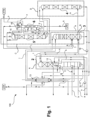
- FIG. 1 an air separation plant according to the invention for obtaining an argon product is shown schematically and designated overall by 100.
- the air separation plant has as separation units a high-pressure column 1, a two-part low-pressure column with a foot section 2 and a head section 3, a crude argon column also divided into two parts with a foot section 4 and a head section 5 and a pure argon column 6.
- the foot section 2 and the head section 3 of the low-pressure column are structurally separated from one another.
- the head section 3 of the low-pressure column is arranged next to the high-pressure column 1 in a vertical plan view, the foot section 2 of the low-pressure column above it.
- the foot section 2 and the head section 3 of the low-pressure column together correspond functionally to a conventional low-pressure column of a Linde double column.
- the high-pressure column 1 and the two column sections 2 and 3 of the low-pressure column thus form a distillation column system for nitrogen-oxygen separation.
- cooled and compressed feed air is fed into the high-pressure column 1 in the form of two streams a and b.
- the streams a and b can be a so-called turbine stream (stream a) on the one hand and a so-called throttle stream (stream b) on the other.
- the air separation plant 100 according to the invention can thus be designed for internal compression.
- the provision of the streams a and b is, for example, in the EP 2 026 024 A1
- atmospheric air can be sucked in by an air compressor via a filter and compressed there to an absolute pressure of 5.0 to 7.0 bar, preferably about 5.5 bar.
- the air can also be compressed to a higher pressure in the air compressor itself or in a further compressor (post-compressor) arranged downstream of it and later expanded via an expansion machine, whereby, for example, part of the cooling requirement of the air separation plant 100 can be covered.
- the air can be cooled, for example in a direct contact cooler in direct heat exchange with cooling water.
- the cooling water can be supplied, for example, from an evaporative cooler and/or from an external source.
- the compressed and cooled air can then be cleaned in a cleaning device. This can, for example, have a pair of containers filled with a suitable adsorption material, preferably molecular sieve.
- the cleaned air is then cooled to approximately the dew point, usually in a main heat exchanger.
- the operating pressures - respectively at the head or the upper part of the head section - are 4.5 to 6.5 bar, preferably about 5.0 bar in the high-pressure column 1 and 1.2 to 1.7 bar, preferably about 1.3 bar in the low-pressure column 2, 3.
- the foot section 2 and the head section 3 of the low-pressure column are preferably operated at essentially the same pressure, although this does not exclude certain pressure differences, for example due to line resistances.
- the high-pressure column 1 and the base section 2 of the low-pressure column are connected in a heat-exchanging manner via a main condenser 12 and are designed as a structural unit.
- the invention can also be used in principle in systems in which the high-pressure column 1 and the low-pressure column (or its base section 2) are arranged separately from one another and have a separate main condenser, i.e. one that is not integrated into the columns.
- Air which is liquefied when the feed air stream b is fed into the high-pressure column 1 can be partly discharged as a corresponding stream c, heated in a subcooling countercurrent device 13, and then used elsewhere or recompressed and provided as feed air stream a, b.
- An oxygen-enriched fraction d is withdrawn from the bottom of the high-pressure column 1, subcooled in the subcooling countercurrent device 13 and, as stream e, partly cooled further in a bottom evaporator 14 of the pure argon column 6. Another part can be passed past the bottom evaporator 14. Part of the stream e flows into the evaporation space of a top condenser 15 of the top section 5 of the two-part crude argon column, another part into the evaporation space of a top condenser 16 of the pure argon column 6. The portion of the oxygen-enriched fraction evaporated in the top condensers 15 and 16 is fed as stream f to the top section 3 of the low-pressure column at a first intermediate point. The remaining liquid portions are fed as stream g to a second intermediate point of the top section 3 of the low-pressure column, which is above the first intermediate point.
- Gaseous nitrogen from the top of the high-pressure column 1 can be partly heated as stream h, for example in the main heat exchanger (not shown), to cool the feed air to approximately ambient temperature and then, for example as in the EP 2 026 024 A1 presented, will be discussed further.
- the remaining gaseous nitrogen from the top of the high-pressure column 1 is at least partially condensed in the main condenser 12.
- the liquid nitrogen produced in this way is partially fed to the high-pressure column 1 as reflux.
- Another part is passed as stream i to the upper part of the top section 3 of the low-pressure column after subcooling in the subcooling countercurrent 13.
- a gaseous nitrogen stream j from the top of the top section 3 of the low-pressure column can be used in different ways or reused in the air separation plant after passing through the subcooling countercurrent 13.
- a liquid oxygen stream k from the sump of the foot section 2 of the low-pressure column can be pressurized by means of a pump 17 and then fed to a liquid oxygen tank (LOX), for example. Part of this oxygen can also be evaporated to provide gaseous compressed oxygen (so-called internal compression).
- LOX liquid oxygen tank
- a stream I flows from the upper part of the foot section 2 of the low-pressure column into the head section 3 of the low-pressure column in its lower region, whereby the foot section 2 and the head section 3 of the low-pressure column are partially functionally coupled.
- an argon-rich stream m is withdrawn from the head section 3 of the low-pressure column and fed into the foot section 4 of the crude argon column.
- the feed takes place directly above the bottom of the foot section 4 of the crude argon column.
- Bottom liquid from the bottom of the head section 3 of the low-pressure column and from the bottom of the foot section 4 of the crude argon column is fed back into the foot section 2 of the low-pressure column via a pump 18 as stream n.
- the top condenser 15 of the top section 5 of the crude argon column can be designed as a reflux condenser. Gas from the upper end of the top section 5 of the crude argon column flows into the reflux passages at the bottom and is partially condensed there. The condensate produced thereby flows downwards in countercurrent to the rising gas in the reflux passages and is used as liquid reflux in the top section 5 of the crude argon column.
- the top condenser 15 On the evaporation side, the top condenser 15 is designed as a bath condenser.
- the cooling fluid which is formed here by the liquid oxygen-enriched fraction from the high-pressure column 1, flows into the evaporation passages at the bottom via one or more side openings and is partially evaporated there.
- the top condenser 15 is therefore designed as a bath evaporator on the evaporation side.
- a crude argon stream n is taken in gaseous form from the upper end of the return passages via a side header and fed to the pure argon column 6 at an intermediate point.
- the top condenser 16 of the pure argon column 6 is designed conventionally on the liquefaction side in the example, i.e. a top gas stream o of the pure argon column 6 flows from top to bottom through the liquefaction passages.
- the top condenser 16 of the pure argon column 6 and/or the main condenser 12 could also be designed as return condensers.
- a residual gas stream p is taken from the top condenser 16 of the pure argon column 6 and, in the example, blown off into the atmosphere (ATM). Alternatively, it can be fed back into the high-pressure column 1 or the low-pressure column 2, 3 and/or in front of the air compressor via a separate blower.
- the bottom liquid of the pure argon column 6 is partially evaporated as stream p in the bottom evaporator 14 and the vapor generated is used as rising gas in the pure argon column 6. The remainder is removed as liquid pure argon product stream q (LAR).
- A designates a first coldbox, which is designed to accommodate the high-pressure column 1 and the foot section 2 of the low-pressure column.
- a second coldbox B can be designed to accommodate the head section 3 of the low-pressure column.
- a third coldbox C is designed to accommodate the head section 5 of the crude argon column.
- the head section 3 of the low-pressure column and the head section 5 of the high-pressure column can also be arranged in a common coldbox.
- Such a coldbox can, for example, have a height of 40 m.
- a fourth coldbox D is shown in a reduced size in the example shown and also has, for example, a height of 40 m.
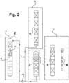
- FIG 2 an air separation plant for obtaining an argon product according to a further embodiment of the invention is shown in an even more schematic manner.
- this air separation plant only columns 2 to 6 are shown, and a representation of the corresponding connections, pumps and heat exchangers has been largely omitted.
- a foot section 4 of the crude argon column is arranged above the head section 3 of the low-pressure column.
- the crude argon column can be subdivided at a different location than that shown in the figure, provided this is expedient for the arrangement according to the invention.
- fluid from the foot section 4 of the crude argon column and from the head section 3 of the low-pressure column can be pumped by means of the pump 18 as stream n into the foot section 3 of the low-pressure column.
- This also applies to alternative arrangements in which the foot section 4 and/or the head section 5 of the crude argon column is arranged geodetically at least partially next to the head section 3 of the low-pressure column. All column sections 1 to 4 can also be arranged geodetically next to each other, at least partially.
- the diameter of the columns can be influenced accordingly by the choice of fittings in the respective columns (sieve trays, packings with different densities), thereby achieving further structural adaptation if necessary.
Landscapes
- Engineering & Computer Science (AREA)
- Physics & Mathematics (AREA)
- Mechanical Engineering (AREA)
- Thermal Sciences (AREA)
- General Engineering & Computer Science (AREA)
- Health & Medical Sciences (AREA)
- Emergency Medicine (AREA)
- Separation By Low-Temperature Treatments (AREA)
Claims (15)
- Installation de séparation d'air (100) qui est conçue pour la récupération d'un produit contenant de l'argon par séparation cryogénique d'air d'alimentation comprimé et refroidi, dans laquelle l'installation de séparation d'air (100) présente une colonne à haute pression (1), une colonne à basse pression réalisée en plusieurs parties et comportant une section de pied (2) et une section de tête (3) disposée de manière à être séparée de celle-ci dans l'espace, ainsi qu'une colonne d'argon brut réalisée en plusieurs parties et comportant une section de pied (4) et une section de tête (5) disposée de manière à être séparée de celle-ci dans l'espace, dans laquelle, dans la colonne à haute pression (1), au moins un écoulement enrichi en oxygène (d) peut être récupéré à partir d'au moins une partie de l'air d'alimentation, dans la colonne à basse pression, au moins un écoulement enrichi en argon (m) peut être récupéré à partir d'au moins une partie de l'écoulement enrichi en oxygène (d), et, dans la colonne d'argon brut, au moins un écoulement riche en argon (n) peut être récupéré à partir d'au moins une partie de l'écoulement enrichi en argon (m),
caractérisée en ce que l'installation de séparation d'air présente une pompe commune (18) au moyen de laquelle au moins un écoulement liquide (n) peut être transféré d'une zone inférieure de la section de tête (3) de la colonne à basse pression et d'une zone inférieure de la section de pied (4) de la colonne d'argon brut vers une zone supérieure de la section de pied (2) de la colonne à basse pression par le fait qu'un premier écoulement liquide peut être soutiré du fond de la section de tête (3) de la colonne à basse pression par l'intermédiaire d'une première conduite et qu'un second écoulement liquide peut être soutiré du fond de la section de pied (4) de la colonne d'argon brut par l'intermédiaire d'une seconde conduite, dans laquelle la première et la seconde conduite sont introduites dans une conduite commune qui est reliée à la pompe commune (18). - Installation de séparation d'air (100) selon la revendication 1, dans laquelle la section de pied (4) et/ou la section de tête (5) de la colonne d'argon brut sont disposées géodésiquement au moins partiellement à côté de la section de tête (3) de la colonne à basse pression.
- Installation de séparation d'air (100) selon la revendication 1, dans laquelle la section de pied (4) ou la section de tête (5) de la colonne d'argon brut est disposée géodésiquement entièrement au-dessus de la section de tête (3) de la colonne à basse pression.
- Installation de séparation d'air (100) selon l'une des revendications précédentes, dans laquelle la section de pied (2) de la colonne à basse pression est disposée, en vue de dessus verticale, à côté de sa section de tête (3) et/ou la section de pied (4) de la colonne d'argon brut est disposée, en vue de dessus verticale, à côté de sa section de tête (5).
- Installation de séparation d'air (100) selon l'une des revendications précédentes, dans laquelle la colonne à haute pression (1) est disposée avec la section de pied (2) de la colonne à basse pression dans une boîte froide.
- Installation de séparation d'air (100) selon l'une des revendications précédentes, dans laquelle la section de pied (4) ou la section de tête (5) de la colonne d'argon brut est disposée avec la section de tête (3) de la colonne à basse pression dans une boîte froide.
- Installation de séparation d'air (100) selon la revendication 6, dans laquelle au moins la boîte froide comportant la section de pied (2) ou la section de tête (3) de la colonne à basse pression et la section de tête (5) de la colonne d'argon brut peut être reliée à d'autres composants de l'installation de séparation d'air (100) au moyen d'un module de tuyauterie.
- Installation de séparation d'air (100) selon l'une des revendications précédentes, dans laquelle la colonne à haute pression (1) et la section de pied (2) de la colonne à basse pression sont réalisées sous la forme d'une unité structurale et sont reliées entre elles avec un échange de chaleur par l'intermédiaire d'un condenseur principal (12).
- Installation de séparation d'air (100) selon l'une des revendications précédentes, laquelle présente en outre une colonne d'argon pur (6), dans laquelle au moins un fluide de la colonne d'argon pur peut être refroidi par l'écoulement enrichi en oxygène (d).
- Procédé pour la récupération d'un produit contenant de l'argon par séparation cryogénique d'air d'alimentation comprimé et refroidi dans une installation de séparation d'air (100) selon l'une des revendications précédentes, dans lequel sont utilisées une colonne à haute pression (1), une colonne à basse pression réalisée en plusieurs parties et comportant une section de pied (2) et une section de tête (3) disposée de manière à être séparée de celle-ci dans l'espace, ainsi qu'une colonne d'argon brut réalisée en plusieurs parties et comportant une section de pied (4) et une section de tête (5) disposée de manière à être séparée de celle-ci dans l'espace, dans lequel, dans la colonne à haute pression (1), au moins un écoulement enrichi en oxygène (d) est récupéré à partir d'au moins une partie de l'air d'alimentation, dans la colonne à basse pression, au moins un écoulement enrichi en argon (m) est récupéré à partir d'au moins une partie de l'écoulement enrichi en oxygène (d), et, dans la colonne d'argon brut, au moins un écoulement riche en argon (n) est récupéré à partir d'au moins une partie de l'écoulement enrichi en argon (m), et dans lequel au moins un écoulement liquide (n) est transféré d'une zone inférieure de la section de tête (3) de la colonne à basse pression et d'une zone inférieure de la section de pied (4) de la colonne d'argon brut vers une zone supérieure de la section de pied (2) de la colonne à basse pression au moyen d'une pompe commune (18) par le fait qu'un premier écoulement liquide est soutiré du fond de la section de tête (3) de la colonne à basse pression par l'intermédiaire d'une première conduite et qu'un second écoulement liquide est soutiré du fond de la section de pied (4) de la colonne d'argon brut par l'intermédiaire d'une seconde conduite, dans lequel la première et la seconde conduite sont introduites dans une conduite commune reliée à la pompe commune (18).
- Procédé selon la revendication 10, dans lequel la section de pied (4) et/ou la section de tête (5) de la colonne d'argon brut sont disposées géodésiquement au moins partiellement à côté de la section de tête (3) de la colonne à basse pression.
- Procédé selon la revendication 10, dans lequel la section de pied (4) ou la section de tête (5) de la colonne d'argon brut est disposée géodésiquement entièrement au-dessus de la section de tête (3) de la colonne à basse pression.
- Procédé pour la fabrication d'une installation de séparation d'air (100) selon l'une des revendications 1 à 9, dans lequel sont fournies une colonne à haute pression (1), une colonne à basse pression réalisée en plusieurs parties et comportant une section de pied (2) et une section de tête (3), ainsi qu'une colonne d'argon brut réalisée en plusieurs parties et comportant une section de pied (4) et une section de tête (5), dans lequel est en outre fournie une pompe commune (18), au moyen de laquelle au moins un écoulement liquide (n) peut être transféré d'une zone inférieure de la section de tête (3) de la colonne à basse pression et d'une zone inférieure de la section de pied (4) de la colonne d'argon brut vers une zone supérieure de la section de pied (2) de la colonne à basse pression par le fait qu'un premier écoulement liquide peut être soutiré du fond de la section de tête (3) de la colonne à basse pression par l'intermédiaire d'une première conduite et qu'un second écoulement liquide peut être soutiré du fond de la section de pied (4) de la colonne d'argon brut par l'intermédiaire d'une seconde conduite, dans lequel la première et la seconde conduite sont introduites dans une conduite commune qui est reliée à la pompe commune (18).
- Procédé selon la revendication 13, dans lequel la section de pied (4) et/ou la section de tête (5) de la colonne d'argon brut sont disposées géodésiquement au moins partiellement à côté de la section de tête (3) de la colonne à basse pression.
- Procédé selon la revendication 13, dans lequel la section de pied (4) ou la section de tête (5) de la colonne d'argon brut est disposée géodésiquement entièrement au-dessus de la section de tête (3) de la colonne à basse pression.
Priority Applications (1)
| Application Number | Priority Date | Filing Date | Title |
|---|---|---|---|
| EP14716232.5A EP2965029B2 (fr) | 2013-03-06 | 2014-03-05 | Installation de séparation d'air, procédé de récupération d'un produit contenant de l'argon et procédé pour créer une installation de séparation d'air |
Applications Claiming Priority (3)
| Application Number | Priority Date | Filing Date | Title |
|---|---|---|---|
| EP13001127 | 2013-03-06 | ||
| PCT/EP2014/000553 WO2014135271A2 (fr) | 2013-03-06 | 2014-03-05 | Installation de séparation d'air, procédé de récupération d'un produit contenant de l'argon et procédé pour créer une installation de séparation d'air |
| EP14716232.5A EP2965029B2 (fr) | 2013-03-06 | 2014-03-05 | Installation de séparation d'air, procédé de récupération d'un produit contenant de l'argon et procédé pour créer une installation de séparation d'air |
Publications (3)
| Publication Number | Publication Date |
|---|---|
| EP2965029A2 EP2965029A2 (fr) | 2016-01-13 |
| EP2965029B1 EP2965029B1 (fr) | 2017-07-12 |
| EP2965029B2 true EP2965029B2 (fr) | 2024-10-30 |
Family
ID=47900434
Family Applications (1)
| Application Number | Title | Priority Date | Filing Date |
|---|---|---|---|
| EP14716232.5A Active EP2965029B2 (fr) | 2013-03-06 | 2014-03-05 | Installation de séparation d'air, procédé de récupération d'un produit contenant de l'argon et procédé pour créer une installation de séparation d'air |
Country Status (10)
| Country | Link |
|---|---|
| US (1) | US10591209B2 (fr) |
| EP (1) | EP2965029B2 (fr) |
| JP (1) | JP6257656B2 (fr) |
| KR (1) | KR102178230B1 (fr) |
| CN (1) | CN105026862B (fr) |
| BR (1) | BR112015020093A2 (fr) |
| CA (1) | CA2900122C (fr) |
| CL (1) | CL2015002367A1 (fr) |
| RU (1) | RU2659698C2 (fr) |
| WO (1) | WO2014135271A2 (fr) |
Families Citing this family (18)
| Publication number | Priority date | Publication date | Assignee | Title |
|---|---|---|---|---|
| EP3040665A1 (fr) * | 2014-12-30 | 2016-07-06 | Linde Aktiengesellschaft | Système de colonne de distillation et installation pour la production d'oxygène par séparation cryogénique de l'air |
| EP3067650B1 (fr) * | 2015-03-13 | 2018-04-25 | Linde Aktiengesellschaft | Installation et procede de production d'oxygene par separation cryogenique de l'air |
| DE102015009563A1 (de) | 2015-07-23 | 2017-01-26 | Linde Aktiengesellschaft | Luftzerlegungsanlage und Luftzerlegungsverfahren |
| EP3176526A1 (fr) | 2015-12-03 | 2017-06-07 | Linde Aktiengesellschaft | Procede et agencement de transfert de fluide |
| US20170176098A1 (en) * | 2015-12-22 | 2017-06-22 | L'air Liquide, Societe Anonyme Pour L'etude Et L'exploitation Des Procedes Georges Claude | Systems and methods for automated startup of an air separation plant |
| WO2019144380A1 (fr) * | 2018-01-26 | 2019-08-01 | L'air Liquide, Societe Anonyme Pour L'etude Et L'exploitation Des Procedes Georges Claude | Unité de séparation d'air par distillation cryogénique |
| CN108731376A (zh) * | 2018-04-18 | 2018-11-02 | 衢州杭氧气体有限公司 | 一种氩气生产工艺及其生产线 |
| JP6557763B1 (ja) * | 2018-08-09 | 2019-08-07 | レール・リキード−ソシエテ・アノニム・プール・レテュード・エ・レクスプロワタシオン・デ・プロセデ・ジョルジュ・クロード | 空気分離装置 |
| EP3614084A1 (fr) | 2018-08-22 | 2020-02-26 | Linde Aktiengesellschaft | Procédé et installation cryogéniques de séparation d'air |
| EP3614082A1 (fr) | 2018-08-22 | 2020-02-26 | Linde Aktiengesellschaft | Installation de séparation d'aire, procédé de séparation d'air à basse température et procédé de fabrication d'une installation de séparation d'aire |
| EP3614083A1 (fr) * | 2018-08-22 | 2020-02-26 | Linde Aktiengesellschaft | Installation de séparation d'aire, procédé de séparation d'air à basse température au moyen de l'installation de séparation d'aire et procédé de fabrication d'une installation de séparation d'aire |
| JP7491716B2 (ja) * | 2020-03-31 | 2024-05-28 | 大陽日酸株式会社 | 空気液化分離装置 |
| US11828532B2 (en) | 2020-12-31 | 2023-11-28 | L'air Liquide Societe Anonyme Pour L'etude Et L'exploitation Des Procedes Georges Claude | Method and apparatus for transfer of liquid |
| WO2022258222A1 (fr) | 2021-06-07 | 2022-12-15 | Linde Gmbh | Installation de séparation d'air et procédé de séparation d'air |
| WO2023001400A1 (fr) | 2021-07-22 | 2023-01-26 | Linde Gmbh | Module de pompe pour une installation de séparation d'air, installation de séparation d'air et procédé de montage |
| US20240377129A1 (en) * | 2021-09-01 | 2024-11-14 | Linde Gmbh | Plant and method for low-temperature air separation |
| US20250085050A1 (en) * | 2021-09-02 | 2025-03-13 | Taiyo Nippon Sanso Corporation | Argon column for air separation unit and air separation unit |
| JP2024163591A (ja) | 2023-05-12 | 2024-11-22 | レール・リキード-ソシエテ・アノニム・プール・レテュード・エ・レクスプロワタシオン・デ・プロセデ・ジョルジュ・クロード | 液化ガス供給システムおよびそれを備える空気分離装置 |
Family Cites Families (31)
| Publication number | Priority date | Publication date | Assignee | Title |
|---|---|---|---|---|
| DE2325422A1 (de) | 1973-05-18 | 1974-12-05 | Linde Ag | Verfahren und vorrichtung zur zerlegung von rohargon |
| SU658372A1 (ru) * | 1976-12-20 | 1979-04-25 | Научно-Исследовательский Институт Технологии Криогенного Машиностроения | Установка разделени воздуха |
| SU851034A1 (ru) * | 1979-09-04 | 1981-07-30 | Предприятие П/Я А-3605 | Установка разделени воздуха |
| DE3428968A1 (de) | 1984-08-06 | 1986-02-13 | Linde Ag, 6200 Wiesbaden | Verfahren und vorrichtung zur zerlegung von rohargon |
| DE3840506A1 (de) | 1988-12-01 | 1990-06-07 | Linde Ag | Verfahren und vorrichtung zur luftzerlegung |
| DE4030749A1 (de) | 1990-09-28 | 1992-04-02 | Linde Ag | Verfahren zur tieftemperaturzerlegung von luft |
| CA2094710C (fr) * | 1990-10-23 | 1998-12-01 | Robert Clyde Dixon | Methode et appareil pour etablir des communications a etalement du spectre |
| DE4317916A1 (de) | 1993-05-28 | 1994-12-01 | Linde Ag | Verfahren und Vorrichtung zur Gewinnung von Argon |
| CA2142318A1 (fr) | 1994-02-24 | 1995-08-25 | Horst Corduan | Methode et appareil pour la recuperation d'argon pur |
| CA2142317A1 (fr) | 1994-02-24 | 1995-08-25 | Anton Moll | Methode et appareil pour la recuperation d'argon pur |
| US5440884A (en) * | 1994-07-14 | 1995-08-15 | Praxair Technology, Inc. | Cryogenic air separation system with liquid air stripping |
| GB9500514D0 (en) * | 1995-01-11 | 1995-03-01 | Boc Group Plc | Air separation |
| DE19609490A1 (de) | 1995-03-10 | 1996-09-12 | Linde Ag | Verfahren und Vorrichtung zur Tieftemperaturzerlegung von Luft |
| GB9513765D0 (en) * | 1995-07-06 | 1995-09-06 | Boc Group Plc | Production of argon |
| GB9521996D0 (en) * | 1995-10-27 | 1996-01-03 | Boc Group Plc | Air separation |
| US6205815B1 (en) * | 1997-04-11 | 2001-03-27 | L'air Liquide, Societe Anonyme Pour L'etude Et L'exploitation Des Procedes Georges Claude | Plant for separation of a gas mixture by distillation |
| FR2761897B1 (fr) * | 1997-04-11 | 1999-05-14 | Air Liquide | Installation de separation d'un melange gazeux par distillation |
| EP0942246A2 (fr) | 1998-03-11 | 1999-09-15 | Linde Aktiengesellschaft | Procédé et appareil pour la séparation de l'air |
| US5970743A (en) * | 1998-06-10 | 1999-10-26 | Air Products And Chemicals, Inc. | Production of argon from a cryogenic air separation process |
| US6347534B1 (en) * | 1999-05-25 | 2002-02-19 | Air Liquide Process And Construction | Cryogenic distillation system for air separation |
| DE19957017A1 (de) | 1999-11-26 | 2001-05-31 | Linde Ag | Vorrichtung zur Gewinnung von Argon |
| DE10040391A1 (de) * | 2000-08-18 | 2002-02-28 | Linde Ag | Tieftemperaturluftzerlegungsanlage |
| DE10045121A1 (de) * | 2000-09-13 | 2002-03-21 | Linde Ag | Verfahren und Vorrichtung zur Gewinnung eines gasförmigen Produkts durch Tieftemperaturzerlegung von Luft |
| DE10103968A1 (de) * | 2001-01-30 | 2002-08-01 | Linde Ag | Drei-Säulen-System zur Tieftemperaturzerlegung von Luft |
| DE10113790A1 (de) | 2001-03-21 | 2002-09-26 | Linde Ag | Drei-Säulen-System zur Tieftemperatur-Luftzerlegung |
| RU2231723C2 (ru) * | 2002-07-29 | 2004-06-27 | Санкт-Петербургский государственный университет низкотемпературных и пищевых технологий | Способ получения чистого аргона методом ректификации воздуха |
| CN100439838C (zh) * | 2006-09-08 | 2008-12-03 | 浙江大学 | 一种节能空分装置 |
| EP2026024A1 (fr) | 2007-07-30 | 2009-02-18 | Linde Aktiengesellschaft | Procédé et dispositif pour la production d'argon par séparation cryogénique d'air |
| FR2946735B1 (fr) * | 2009-06-12 | 2012-07-13 | Air Liquide | Appareil et procede de separation d'air par distillation cryogenique. |
| US8899075B2 (en) * | 2010-11-18 | 2014-12-02 | Praxair Technology, Inc. | Air separation method and apparatus |
| FR2964451B3 (fr) * | 2011-12-05 | 2012-10-12 | Air Liquide | Installation de separation d'un gaz de l'air par separation cryogenique |
-
2014
- 2014-03-05 US US14/765,847 patent/US10591209B2/en active Active
- 2014-03-05 RU RU2015142384A patent/RU2659698C2/ru active
- 2014-03-05 EP EP14716232.5A patent/EP2965029B2/fr active Active
- 2014-03-05 BR BR112015020093A patent/BR112015020093A2/pt not_active IP Right Cessation
- 2014-03-05 CA CA2900122A patent/CA2900122C/fr active Active
- 2014-03-05 WO PCT/EP2014/000553 patent/WO2014135271A2/fr not_active Ceased
- 2014-03-05 KR KR1020157027209A patent/KR102178230B1/ko active Active
- 2014-03-05 JP JP2015560582A patent/JP6257656B2/ja active Active
- 2014-03-05 CN CN201480011523.4A patent/CN105026862B/zh active Active
-
2015
- 2015-08-24 CL CL2015002367A patent/CL2015002367A1/es unknown
Also Published As
| Publication number | Publication date |
|---|---|
| US10591209B2 (en) | 2020-03-17 |
| KR102178230B1 (ko) | 2020-11-12 |
| EP2965029B1 (fr) | 2017-07-12 |
| JP2016515188A (ja) | 2016-05-26 |
| BR112015020093A2 (pt) | 2017-07-18 |
| CA2900122A1 (fr) | 2014-09-12 |
| CN105026862A (zh) | 2015-11-04 |
| JP6257656B2 (ja) | 2018-01-10 |
| WO2014135271A2 (fr) | 2014-09-12 |
| CA2900122C (fr) | 2023-10-31 |
| RU2659698C2 (ru) | 2018-07-03 |
| US20150369535A1 (en) | 2015-12-24 |
| CL2015002367A1 (es) | 2016-03-04 |
| EP2965029A2 (fr) | 2016-01-13 |
| RU2015142384A (ru) | 2017-04-10 |
| KR20150126001A (ko) | 2015-11-10 |
| WO2014135271A3 (fr) | 2015-01-08 |
| CN105026862B (zh) | 2018-03-27 |
Similar Documents
| Publication | Publication Date | Title |
|---|---|---|
| EP2965029B2 (fr) | Installation de séparation d'air, procédé de récupération d'un produit contenant de l'argon et procédé pour créer une installation de séparation d'air | |
| EP3870915B1 (fr) | Procédé et installation de séparation d'air à basse température | |
| EP2236964B1 (fr) | Procédé et dispositif de séparation de l'air à basse température | |
| EP1482266B1 (fr) | Procédé et dispositif pour la récupération de Krypton et/ou Xénon par séparation cryogénique d'air | |
| WO2021204424A2 (fr) | Procédé de séparation d'air à basse température, installation de séparation d'air et ensemble composé d'au moins deux installations de séparation d'air | |
| WO2020169257A1 (fr) | Procédé et installation de décomposition d'air à basse température | |
| DE10228111A1 (de) | Luftzerlegungsverfahren und -anlage mit Mischsäule und Krypton-Xenon-Gewinnung | |
| EP2986924B1 (fr) | Dispositif pouvant être rééquipé, destiné à la décomposition à basse température de l'air, installation pouvant être rééquipée et procédé de rééquipement d'une installation de décomposition de l'air à basse température | |
| WO2016058666A1 (fr) | Procédé et dispositif de récupération variable d'argon par fractionnement à basse température | |
| EP3327393A1 (fr) | Procédé et dispositif de production d'un flux de produit d'oxygène ultrapur par cryogénie de séparation d'air | |
| EP3980705A1 (fr) | Procédé et installation de décomposition d'air à basse température | |
| WO2016146246A1 (fr) | Système permettant de produire de l'oxygène par fractionnement d'air à basse température | |
| EP3067649A1 (fr) | Système de colonnes de distillation et procédé de production d'oxygène par séparation cryogénique de l'air | |
| EP2914913B1 (fr) | Procédé de séparation d'air à basse température dans une installation de séparation d'air et installation de séparation d'air | |
| EP4065910A1 (fr) | Procédé et installation pour fractionnement à basse température de l'air | |
| EP3067650A1 (fr) | Installation et procede de production d'oxygene par separation cryogenique de l'air | |
| WO2023030682A2 (fr) | Installation et procédé de séparation cryogénique de l'air | |
| WO2023083488A1 (fr) | Procédé et agencement de production d'un produit à base d'argon et d'un produit à base d'oxygène et procédé de rénovation d'une ou de plusieurs installations de fractionnement d'air | |
| EP2703757A1 (fr) | Procédé et installation destinés à générer des produits à base d'oxygène liquides et gazeux par décomposition à basse température de l'air | |
| WO2020187449A1 (fr) | Procédé et installation de décomposition d'air à basse température | |
| DE10248656A1 (de) | Verfahren zur Gewinnung von Krypton und/oder Xenon durch Tieftemperaturzerlegung von Luft | |
| EP3614084A1 (fr) | Procédé et installation cryogéniques de séparation d'air | |
| WO2020038606A1 (fr) | Installation de séparation d'air, procédé pour séparer l'air à basse température au moyen de l'installation de séparation d'air et procédé pour réaliser une installation de séparation d'air | |
| EP4320397A1 (fr) | Procédé et installation de fractionnement à basse température d'air | |
| WO2023001400A1 (fr) | Module de pompe pour une installation de séparation d'air, installation de séparation d'air et procédé de montage |
Legal Events
| Date | Code | Title | Description |
|---|---|---|---|
| PUAI | Public reference made under article 153(3) epc to a published international application that has entered the european phase |
Free format text: ORIGINAL CODE: 0009012 |
|
| 17P | Request for examination filed |
Effective date: 20150723 |
|
| AK | Designated contracting states |
Kind code of ref document: A2 Designated state(s): AL AT BE BG CH CY CZ DE DK EE ES FI FR GB GR HR HU IE IS IT LI LT LU LV MC MK MT NL NO PL PT RO RS SE SI SK SM TR |
|
| AX | Request for extension of the european patent |
Extension state: BA ME |
|
| DAX | Request for extension of the european patent (deleted) | ||
| GRAP | Despatch of communication of intention to grant a patent |
Free format text: ORIGINAL CODE: EPIDOSNIGR1 |
|
| STAA | Information on the status of an ep patent application or granted ep patent |
Free format text: STATUS: GRANT OF PATENT IS INTENDED |
|
| INTG | Intention to grant announced |
Effective date: 20170111 |
|
| GRAS | Grant fee paid |
Free format text: ORIGINAL CODE: EPIDOSNIGR3 |
|
| GRAJ | Information related to disapproval of communication of intention to grant by the applicant or resumption of examination proceedings by the epo deleted |
Free format text: ORIGINAL CODE: EPIDOSDIGR1 |
|
| GRAL | Information related to payment of fee for publishing/printing deleted |
Free format text: ORIGINAL CODE: EPIDOSDIGR3 |
|
| STAA | Information on the status of an ep patent application or granted ep patent |
Free format text: STATUS: REQUEST FOR EXAMINATION WAS MADE |
|
| INTC | Intention to grant announced (deleted) | ||
| GRAR | Information related to intention to grant a patent recorded |
Free format text: ORIGINAL CODE: EPIDOSNIGR71 |
|
| STAA | Information on the status of an ep patent application or granted ep patent |
Free format text: STATUS: GRANT OF PATENT IS INTENDED |
|
| GRAA | (expected) grant |
Free format text: ORIGINAL CODE: 0009210 |
|
| STAA | Information on the status of an ep patent application or granted ep patent |
Free format text: STATUS: THE PATENT HAS BEEN GRANTED |
|
| INTG | Intention to grant announced |
Effective date: 20170531 |
|
| AK | Designated contracting states |
Kind code of ref document: B1 Designated state(s): AL AT BE BG CH CY CZ DE DK EE ES FI FR GB GR HR HU IE IS IT LI LT LU LV MC MK MT NL NO PL PT RO RS SE SI SK SM TR |
|
| REG | Reference to a national code |
Ref country code: GB Ref legal event code: FG4D Free format text: NOT ENGLISH |
|
| REG | Reference to a national code |
Ref country code: CH Ref legal event code: EP |
|
| REG | Reference to a national code |
Ref country code: AT Ref legal event code: REF Ref document number: 908739 Country of ref document: AT Kind code of ref document: T Effective date: 20170715 |
|
| REG | Reference to a national code |
Ref country code: IE Ref legal event code: FG4D Free format text: LANGUAGE OF EP DOCUMENT: GERMAN |
|
| REG | Reference to a national code |
Ref country code: DE Ref legal event code: R096 Ref document number: 502014004557 Country of ref document: DE |
|
| REG | Reference to a national code |
Ref country code: NL Ref legal event code: MP Effective date: 20170712 |
|
| REG | Reference to a national code |
Ref country code: LT Ref legal event code: MG4D |
|
| PG25 | Lapsed in a contracting state [announced via postgrant information from national office to epo] |
Ref country code: NL Free format text: LAPSE BECAUSE OF FAILURE TO SUBMIT A TRANSLATION OF THE DESCRIPTION OR TO PAY THE FEE WITHIN THE PRESCRIBED TIME-LIMIT Effective date: 20170712 Ref country code: SE Free format text: LAPSE BECAUSE OF FAILURE TO SUBMIT A TRANSLATION OF THE DESCRIPTION OR TO PAY THE FEE WITHIN THE PRESCRIBED TIME-LIMIT Effective date: 20170712 Ref country code: HR Free format text: LAPSE BECAUSE OF FAILURE TO SUBMIT A TRANSLATION OF THE DESCRIPTION OR TO PAY THE FEE WITHIN THE PRESCRIBED TIME-LIMIT Effective date: 20170712 Ref country code: NO Free format text: LAPSE BECAUSE OF FAILURE TO SUBMIT A TRANSLATION OF THE DESCRIPTION OR TO PAY THE FEE WITHIN THE PRESCRIBED TIME-LIMIT Effective date: 20171012 Ref country code: FI Free format text: LAPSE BECAUSE OF FAILURE TO SUBMIT A TRANSLATION OF THE DESCRIPTION OR TO PAY THE FEE WITHIN THE PRESCRIBED TIME-LIMIT Effective date: 20170712 Ref country code: LT Free format text: LAPSE BECAUSE OF FAILURE TO SUBMIT A TRANSLATION OF THE DESCRIPTION OR TO PAY THE FEE WITHIN THE PRESCRIBED TIME-LIMIT Effective date: 20170712 |
|
| REG | Reference to a national code |
Ref country code: FR Ref legal event code: PLFP Year of fee payment: 5 |
|
| PG25 | Lapsed in a contracting state [announced via postgrant information from national office to epo] |
Ref country code: ES Free format text: LAPSE BECAUSE OF FAILURE TO SUBMIT A TRANSLATION OF THE DESCRIPTION OR TO PAY THE FEE WITHIN THE PRESCRIBED TIME-LIMIT Effective date: 20170712 Ref country code: RS Free format text: LAPSE BECAUSE OF FAILURE TO SUBMIT A TRANSLATION OF THE DESCRIPTION OR TO PAY THE FEE WITHIN THE PRESCRIBED TIME-LIMIT Effective date: 20170712 Ref country code: GR Free format text: LAPSE BECAUSE OF FAILURE TO SUBMIT A TRANSLATION OF THE DESCRIPTION OR TO PAY THE FEE WITHIN THE PRESCRIBED TIME-LIMIT Effective date: 20171013 Ref country code: LV Free format text: LAPSE BECAUSE OF FAILURE TO SUBMIT A TRANSLATION OF THE DESCRIPTION OR TO PAY THE FEE WITHIN THE PRESCRIBED TIME-LIMIT Effective date: 20170712 Ref country code: BG Free format text: LAPSE BECAUSE OF FAILURE TO SUBMIT A TRANSLATION OF THE DESCRIPTION OR TO PAY THE FEE WITHIN THE PRESCRIBED TIME-LIMIT Effective date: 20171012 Ref country code: PL Free format text: LAPSE BECAUSE OF FAILURE TO SUBMIT A TRANSLATION OF THE DESCRIPTION OR TO PAY THE FEE WITHIN THE PRESCRIBED TIME-LIMIT Effective date: 20170712 Ref country code: IS Free format text: LAPSE BECAUSE OF FAILURE TO SUBMIT A TRANSLATION OF THE DESCRIPTION OR TO PAY THE FEE WITHIN THE PRESCRIBED TIME-LIMIT Effective date: 20171112 |
|
| REG | Reference to a national code |
Ref country code: DE Ref legal event code: R026 Ref document number: 502014004557 Country of ref document: DE |
|
| PLBI | Opposition filed |
Free format text: ORIGINAL CODE: 0009260 |
|
| PLAX | Notice of opposition and request to file observation + time limit sent |
Free format text: ORIGINAL CODE: EPIDOSNOBS2 |
|
| PG25 | Lapsed in a contracting state [announced via postgrant information from national office to epo] |
Ref country code: DK Free format text: LAPSE BECAUSE OF FAILURE TO SUBMIT A TRANSLATION OF THE DESCRIPTION OR TO PAY THE FEE WITHIN THE PRESCRIBED TIME-LIMIT Effective date: 20170712 Ref country code: RO Free format text: LAPSE BECAUSE OF FAILURE TO SUBMIT A TRANSLATION OF THE DESCRIPTION OR TO PAY THE FEE WITHIN THE PRESCRIBED TIME-LIMIT Effective date: 20170712 Ref country code: CZ Free format text: LAPSE BECAUSE OF FAILURE TO SUBMIT A TRANSLATION OF THE DESCRIPTION OR TO PAY THE FEE WITHIN THE PRESCRIBED TIME-LIMIT Effective date: 20170712 |
|
| 26 | Opposition filed |
Opponent name: L'AIR LIQUIDE, SOCIETE ANONYME POUR L'ETUDE ET L'E Effective date: 20180411 |
|
| PG25 | Lapsed in a contracting state [announced via postgrant information from national office to epo] |
Ref country code: EE Free format text: LAPSE BECAUSE OF FAILURE TO SUBMIT A TRANSLATION OF THE DESCRIPTION OR TO PAY THE FEE WITHIN THE PRESCRIBED TIME-LIMIT Effective date: 20170712 Ref country code: SM Free format text: LAPSE BECAUSE OF FAILURE TO SUBMIT A TRANSLATION OF THE DESCRIPTION OR TO PAY THE FEE WITHIN THE PRESCRIBED TIME-LIMIT Effective date: 20170712 Ref country code: IT Free format text: LAPSE BECAUSE OF FAILURE TO SUBMIT A TRANSLATION OF THE DESCRIPTION OR TO PAY THE FEE WITHIN THE PRESCRIBED TIME-LIMIT Effective date: 20170712 Ref country code: SK Free format text: LAPSE BECAUSE OF FAILURE TO SUBMIT A TRANSLATION OF THE DESCRIPTION OR TO PAY THE FEE WITHIN THE PRESCRIBED TIME-LIMIT Effective date: 20170712 |
|
| PG25 | Lapsed in a contracting state [announced via postgrant information from national office to epo] |
Ref country code: SI Free format text: LAPSE BECAUSE OF FAILURE TO SUBMIT A TRANSLATION OF THE DESCRIPTION OR TO PAY THE FEE WITHIN THE PRESCRIBED TIME-LIMIT Effective date: 20170712 |
|
| PLBB | Reply of patent proprietor to notice(s) of opposition received |
Free format text: ORIGINAL CODE: EPIDOSNOBS3 |
|
| PG25 | Lapsed in a contracting state [announced via postgrant information from national office to epo] |
Ref country code: MT Free format text: LAPSE BECAUSE OF FAILURE TO SUBMIT A TRANSLATION OF THE DESCRIPTION OR TO PAY THE FEE WITHIN THE PRESCRIBED TIME-LIMIT Effective date: 20170712 |
|
| REG | Reference to a national code |
Ref country code: CH Ref legal event code: PL |
|
| PG25 | Lapsed in a contracting state [announced via postgrant information from national office to epo] |
Ref country code: MC Free format text: LAPSE BECAUSE OF FAILURE TO SUBMIT A TRANSLATION OF THE DESCRIPTION OR TO PAY THE FEE WITHIN THE PRESCRIBED TIME-LIMIT Effective date: 20170712 |
|
| REG | Reference to a national code |
Ref country code: BE Ref legal event code: MM Effective date: 20180331 |
|
| REG | Reference to a national code |
Ref country code: IE Ref legal event code: MM4A |
|
| PG25 | Lapsed in a contracting state [announced via postgrant information from national office to epo] |
Ref country code: LU Free format text: LAPSE BECAUSE OF NON-PAYMENT OF DUE FEES Effective date: 20180305 |
|
| PG25 | Lapsed in a contracting state [announced via postgrant information from national office to epo] |
Ref country code: IE Free format text: LAPSE BECAUSE OF NON-PAYMENT OF DUE FEES Effective date: 20180305 |
|
| PG25 | Lapsed in a contracting state [announced via postgrant information from national office to epo] |
Ref country code: BE Free format text: LAPSE BECAUSE OF NON-PAYMENT OF DUE FEES Effective date: 20180331 Ref country code: LI Free format text: LAPSE BECAUSE OF NON-PAYMENT OF DUE FEES Effective date: 20180331 Ref country code: CH Free format text: LAPSE BECAUSE OF NON-PAYMENT OF DUE FEES Effective date: 20180331 |
|
| PG25 | Lapsed in a contracting state [announced via postgrant information from national office to epo] |
Ref country code: TR Free format text: LAPSE BECAUSE OF FAILURE TO SUBMIT A TRANSLATION OF THE DESCRIPTION OR TO PAY THE FEE WITHIN THE PRESCRIBED TIME-LIMIT Effective date: 20170712 |
|
| PLBP | Opposition withdrawn |
Free format text: ORIGINAL CODE: 0009264 |
|
| PG25 | Lapsed in a contracting state [announced via postgrant information from national office to epo] |
Ref country code: PT Free format text: LAPSE BECAUSE OF FAILURE TO SUBMIT A TRANSLATION OF THE DESCRIPTION OR TO PAY THE FEE WITHIN THE PRESCRIBED TIME-LIMIT Effective date: 20170712 |
|
| RDAF | Communication despatched that patent is revoked |
Free format text: ORIGINAL CODE: EPIDOSNREV1 |
|
| RAP2 | Party data changed (patent owner data changed or rights of a patent transferred) |
Owner name: LINDE GMBH |
|
| PG25 | Lapsed in a contracting state [announced via postgrant information from national office to epo] |
Ref country code: HU Free format text: LAPSE BECAUSE OF FAILURE TO SUBMIT A TRANSLATION OF THE DESCRIPTION OR TO PAY THE FEE WITHIN THE PRESCRIBED TIME-LIMIT; INVALID AB INITIO Effective date: 20140305 Ref country code: CY Free format text: LAPSE BECAUSE OF FAILURE TO SUBMIT A TRANSLATION OF THE DESCRIPTION OR TO PAY THE FEE WITHIN THE PRESCRIBED TIME-LIMIT Effective date: 20170712 Ref country code: MK Free format text: LAPSE BECAUSE OF NON-PAYMENT OF DUE FEES Effective date: 20170712 |
|
| RDAE | Information deleted related to despatch of communication that patent is revoked |
Free format text: ORIGINAL CODE: EPIDOSDREV1 |
|
| REG | Reference to a national code |
Ref country code: DE Ref legal event code: R081 Ref document number: 502014004557 Country of ref document: DE Owner name: LINDE GMBH, DE Free format text: FORMER OWNER: LINDE AKTIENGESELLSCHAFT, 80331 MUENCHEN, DE |
|
| RDAF | Communication despatched that patent is revoked |
Free format text: ORIGINAL CODE: EPIDOSNREV1 |
|
| PG25 | Lapsed in a contracting state [announced via postgrant information from national office to epo] |
Ref country code: AL Free format text: LAPSE BECAUSE OF FAILURE TO SUBMIT A TRANSLATION OF THE DESCRIPTION OR TO PAY THE FEE WITHIN THE PRESCRIBED TIME-LIMIT Effective date: 20170712 |
|
| REG | Reference to a national code |
Ref country code: AT Ref legal event code: MM01 Ref document number: 908739 Country of ref document: AT Kind code of ref document: T Effective date: 20190305 |
|
| APBM | Appeal reference recorded |
Free format text: ORIGINAL CODE: EPIDOSNREFNO |
|
| APBP | Date of receipt of notice of appeal recorded |
Free format text: ORIGINAL CODE: EPIDOSNNOA2O |
|
| APAH | Appeal reference modified |
Free format text: ORIGINAL CODE: EPIDOSCREFNO |
|
| PLAB | Opposition data, opponent's data or that of the opponent's representative modified |
Free format text: ORIGINAL CODE: 0009299OPPO |
|
| PG25 | Lapsed in a contracting state [announced via postgrant information from national office to epo] |
Ref country code: AT Free format text: LAPSE BECAUSE OF NON-PAYMENT OF DUE FEES Effective date: 20190305 |
|
| APBQ | Date of receipt of statement of grounds of appeal recorded |
Free format text: ORIGINAL CODE: EPIDOSNNOA3O |
|
| P01 | Opt-out of the competence of the unified patent court (upc) registered |
Effective date: 20230525 |
|
| APBU | Appeal procedure closed |
Free format text: ORIGINAL CODE: EPIDOSNNOA9O |
|
| PUAH | Patent maintained in amended form |
Free format text: ORIGINAL CODE: 0009272 |
|
| STAA | Information on the status of an ep patent application or granted ep patent |
Free format text: STATUS: PATENT MAINTAINED AS AMENDED |
|
| 27A | Patent maintained in amended form |
Effective date: 20241030 |
|
| AK | Designated contracting states |
Kind code of ref document: B2 Designated state(s): AL AT BE BG CH CY CZ DE DK EE ES FI FR GB GR HR HU IE IS IT LI LT LU LV MC MK MT NL NO PL PT RO RS SE SI SK SM TR |
|
| REG | Reference to a national code |
Ref country code: DE Ref legal event code: R102 Ref document number: 502014004557 Country of ref document: DE |
|
| PGFP | Annual fee paid to national office [announced via postgrant information from national office to epo] |
Ref country code: GB Payment date: 20260324 Year of fee payment: 13 |
|
| PGFP | Annual fee paid to national office [announced via postgrant information from national office to epo] |
Ref country code: DE Payment date: 20260320 Year of fee payment: 13 |
|
| PGFP | Annual fee paid to national office [announced via postgrant information from national office to epo] |
Ref country code: FR Payment date: 20260324 Year of fee payment: 13 |