EP2965046B1 - Kabeldichtung für eine detektoranordnung - Google Patents
Kabeldichtung für eine detektoranordnung Download PDFInfo
- Publication number
- EP2965046B1 EP2965046B1 EP14760399.7A EP14760399A EP2965046B1 EP 2965046 B1 EP2965046 B1 EP 2965046B1 EP 14760399 A EP14760399 A EP 14760399A EP 2965046 B1 EP2965046 B1 EP 2965046B1
- Authority
- EP
- European Patent Office
- Prior art keywords
- sealant
- detector
- generally
- wire
- head assembly
- Prior art date
- Legal status (The legal status is an assumption and is not a legal conclusion. Google has not performed a legal analysis and makes no representation as to the accuracy of the status listed.)
- Active
Links
Images


Classifications
-
- G—PHYSICS
- G01—MEASURING; TESTING
- G01D—MEASURING NOT SPECIALLY ADAPTED FOR A SPECIFIC VARIABLE; ARRANGEMENTS FOR MEASURING TWO OR MORE VARIABLES NOT COVERED IN A SINGLE OTHER SUBCLASS; TARIFF METERING APPARATUS; MEASURING OR TESTING NOT OTHERWISE PROVIDED FOR
- G01D11/00—Component parts of measuring arrangements not specially adapted for a specific variable
- G01D11/24—Housings ; Casings for instruments
- G01D11/245—Housings for sensors
-
- G—PHYSICS
- G01—MEASURING; TESTING
- G01D—MEASURING NOT SPECIALLY ADAPTED FOR A SPECIFIC VARIABLE; ARRANGEMENTS FOR MEASURING TWO OR MORE VARIABLES NOT COVERED IN A SINGLE OTHER SUBCLASS; TARIFF METERING APPARATUS; MEASURING OR TESTING NOT OTHERWISE PROVIDED FOR
- G01D21/00—Measuring or testing not otherwise provided for
-
- G—PHYSICS
- G01—MEASURING; TESTING
- G01N—INVESTIGATING OR ANALYSING MATERIALS BY DETERMINING THEIR CHEMICAL OR PHYSICAL PROPERTIES
- G01N33/00—Investigating or analysing materials by specific methods not covered by groups G01N1/00 - G01N31/00
- G01N33/0004—Gaseous mixtures, e.g. polluted air
- G01N33/0009—General constructional details of gas analysers, e.g. portable test equipment
- G01N33/0027—General constructional details of gas analysers, e.g. portable test equipment concerning the detector
- G01N33/0036—General constructional details of gas analysers, e.g. portable test equipment concerning the detector specially adapted to detect a particular component
- G01N33/0057—Warfare agents or explosives
-
- G—PHYSICS
- G01—MEASURING; TESTING
- G01N—INVESTIGATING OR ANALYSING MATERIALS BY DETERMINING THEIR CHEMICAL OR PHYSICAL PROPERTIES
- G01N33/00—Investigating or analysing materials by specific methods not covered by groups G01N1/00 - G01N31/00
- G01N33/22—Fuels; Explosives
Definitions
- Environmental detection systems may include a variety of sensors for detecting the presence and/or concentration of various chemicals in various environments.
- sensors may be used in hazardous environments for detecting the presence and/or concentration of hazardous (e.g., volatile, combustible, explosive, and/or toxic) gases and/or vapors.
- hazardous e.g., volatile, combustible, explosive, and/or toxic
- At least some known detection systems are used in environments containing combustible and/or explosive gases and/or vapors.
- the sensors of such detection systems are typically mounted to a mounting structure having an explosion-resistant housing.
- the explosion-resistant housing has an interior chamber that is hermetically sealed to separate a volume of space within the housing from the environment.
- the sensors include one or more wires that connect a sensing element of the sensor to one or more processing components, power supply components, and/or communication components, each of which may be held within the interior chamber of the housing or further upstream.
- the wire(s) extend from the sensing element and pass through a body of the sensor into the interior chamber of the housing.
- the interior chamber of the housing is separated from the environment such that any combustion and/or explosion within the interior chamber is less likely to extend into the environment.
- At least some known detection systems use heat-cured epoxy sealants to seal the wire(s) to the body of the sensor in an attempt to prevent any combustion and/or explosion within the interior chamber from extending into the environment through the interface between the wire(s) and the body of sensor (i.e., along the path of the wire(s) through the body of the sensor).
- heat-cured epoxy sealants may lose adhesion to the body of the sensor over time, for example because of fatigue, environmental and/or chemical exposure, and/or different thermal expansion and contraction of the different materials of the epoxy and the body of the sensor.
- heat-cured epoxy sealants may have tolerance issues with regard to the density and/or thermal coefficient of expansion of the epoxy, for example because of processing variations in material compounding, mixing, and/or post curing temperatures.
- the loss of adhesion and/or the tolerance issues of the heat-cured epoxy may cause the heat-cured epoxy to fail to maintain a seal at the interface between the wire(s) and the body of the sensor, which may enable an explosion and/or combustion within the interior chamber of the housing to extend into the environment. Accordingly, using a heat-cured epoxy sealant to seal the wire(s) to the body of the sensor may present safety issues in explosive and/or combustible environments.
- US2008/149483 discloses an arrangement in which a tapering seal is associated with a wire in a gas sensor, the outer tapering surface of which seal engages with a tapering surface provided in a housing.
- the wire passes through a chamber within the seal, and the camming action between the seal and the surrounding tapering surface results in radial compression of the seal onto the wire as the seal is pushed into the housing when the wire is pulled through the housing.
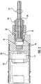
- the invention includes a sensor connector assembly 12 with a plurality of sensor connection wires 14 having single round solid conductors and a thickness of polymer insulation.
- the sensor connector assembly 12 is retained in the detector head housing 28 with retaining ring 10.
- the connection wires 14 are sealed to the detector head housing 28 by sliding the wires through the preformed holes in the pliable 16 and rigid 18 sealants until seated in the detector head housing 28.
- the seal around the wires is achieved by compressing the pliable sealant 16 between the rigid sealants 18.
- the invention includes a preformed graphite Grade GHA-J with a corrosion resistant inhibitor pliable sealant 16 and ceramic Al 2 O 3 , at least 96% pure rigid sealant 18.
- the sealants 16, 18 are compressed in the housing 28 by means of the follower sleeve 20.
- the follower sleeve 20 is pushed by the compression nut 24 as it is threaded into the detector head housing 28. This is controlled by applying rotational torque to compression nut 24, until the pliable sealant 16, flows around the wiring 14 and the rigid sealants 18, filling the voids between the wires and the sealant cavity in detector head housing 28.
- the pliable sealant 10 flows under dynamic pressure providing an increase in seal pressure when subjected to explosive gas or vapor pressure.
- the follower sleeve 20 is held from rotation by the anti-rotation pin 22.
- a rubber sleeve 26 is assembled over the connection wiring 14, and pressed into and retained in the hole in compression nut 24.
- the invention includes a gas detector head with dynamic flame path wire seal, as shown in Figures 1 and 2 , having a gas sensor connector assembly 12.
- the gas detector head with dynamic flame path wire seal has a sensor connector assembly with a plurality of sensor connection wires with single round solid conductors with a thickness of polymer insulation 14, more preferably with preformed pliable sealant 16, still more preferably with preformed pliable sealant between rigid sealants 18, and most preferably compressed with a follower sleeve 20.
- the follower sleeve 20 preferably has an anti-rotation pin 22, which is more preferably retained into detector head housing 28, which is most preferably retained with compression nut 24.
- the mounting structure 114 supports the sensor 112 such that the sensor 112 is exposed within the environment 116 for performing sensing operations.
- the mounting structure 114 may include processing components, power supply components, communications components, and/or the like that support operation of the sensor 112.
- an interior chamber 118 of the mounting structure 14 may hold one or more electrical power sources (not shown; e.g., a battery and/or the like) and/or one or more electrical power distribution components (not shown; e.g. electrical wires and/or cables, circuit boards, switches, relays, transformers, capacitors, voltage regulators, current regulators, and/or the like) for supplying electrical power to the sensor 112 to power operation of the sensor 112.
- the interior chamber 118 of the mounting structure 14 may hold one or more processing components (not shown; e.g., computers, processors, controllers, microprocessors, circuit boards, microcontrollers, memories, integrated circuits, and/or the like) that process signals from the sensor 112 that represent the parameter(s) sensed by the sensor 112. Processing of signals from the sensor 112 optionally includes data logging operations.
- processing components e.g., computers, processors, controllers, microprocessors, circuit boards, microcontrollers, memories, integrated circuits, and/or the like
- Processing of signals from the sensor 112 optionally includes data logging operations.
- the interior chamber 118 of the mounting structure 114 may hold one or more communication components (not shown; e.g., electrical wires and/or cables, circuit boards, other electrical pathways, switches, relays, communication nodes, and/or the like) that enables the sensor 112 to communicate with a remote location and/or other sensors.
- the remote location and/or the other sensors may contain one or more processing components and/or electrical power components that relate to operation of the sensor 112.
- the mounting structure 114 may include any structure, means, configuration, and/or the like that enables the mounting structure 114 to support the sensor 112 within the environment 116.
- the interior chamber 118 of the mounting structure 114 is hermetically sealed to separate a volume of space within the mounting structure 114 from the environment 116.
- the mounting structure 114 is an explosion-resistant housing and interior chamber 18 holds one or more processing components, power supply components, and/or communication components that relate to operation of the sensor 112.
- the interior chamber 118 is separated from the environment 116 such that any combustion and/or explosion within the interior chamber 118 is less likely to extend into the environment 116.
- any combustion and/or explosion that occurs within the interior chamber 118 is less likely to cause any substance within the environment to combust and/or explode.
- the illustrated embodiment of the mounting structure 114 may be commonly referred to as an "explosion-proof transmitter enclosure.” Although described above as being an active sensor that requires a supply of electrical power to operate, the sensor 112 may be a passive sensor that does not require a supply of electrical power to operate.
- FIG 4 is an exploded perspective view of an embodiment of the sensor 112.
- the sensor 112 includes a detector head assembly 120 and a retaining cap 124.
- the detector head assembly 120 includes a sensor cartridge 122.
- the sensor 112 is elongated and extends along a central longitudinal axis 128.
- the detector head assembly 120 is electrically connected to the mounting structure 114 (shown in Figures 3 and 5 ), the processing component(s), the power supply component(s), and/or the communication component(s) via one or more electrical wires 130 (which may or may not be grouped together in an electrical cable).
- the detector head assembly 120 may include an attachment member 144 for mounting the retaining cap 124 to the detector body 132.
- the illustrated embodiment of the attachment member 144 includes a thread 146 that enables the retaining cap 124 to be mounted to the detector body 132 by being threadably connected to the detector body 132.
- the attachment member 144 may use any other mounting strategy for mounting the retaining cap 124 to the detector body 132, such as, but not limited to, an adhesive, an interference fit, a snap-fit, a latch, a clip, a clamp, a threaded fastener, and/or the like.
- the attachment member 144 is shown as being formed at the end 136 of the detector body 132, the attachment member 144 may have any other location along the detector body 132.
- the detector head assembly 120 includes a wire seal 180 that is configured to seal the wires 130 to the detector body 132 and each other to facilitate preventing a combustion and/or an explosion that occurs within the interior chamber 118 (shown in Figures 3 and 5 ) of the mounting structure 114 from extending into the environment 116 through the internal channel 138 of the detector body 132.
- the wire seal 180 includes a generally pliable sealant 182.
- the wire seal 180 may also include a generally rigid sealant 184, a sleeve 186, a compression nut 188, an anti-rotation pin 190, and/or an elastomeric sleeve 192.
- the sensor 112 includes a plurality of the wires 130 in the illustrated embodiment. But, the sensor 112 may include any number of the wires 130, including embodiments wherein the sensor 112 only includes one of the wires 130.
- Each wire 130 includes a conductor 194 and an insulation layer 196 surrounding the conductor 194.
- the conductor 194 of each wire 130 may be an electrical conductor or an optical conductor. In some embodiments, one or more of the wires 130 includes an electrical conductor 194 and one or more of the wires 130 includes an optical conductor 194.
- each wire 130 extends from the interior chamber 118 of the mounting structure 114 and into the internal channel 138 of the detector body 132 through the end 134 such that ends 198 of the conductors 194 are operatively (e.g., electrically and/or optically) connected to the connector 170.
- the wire seal 180 is configured to seal the wires 130 to the detector body 132 and each other to facilitate preventing a combustion and/or an explosion that occurs within the interior chamber 118 of the mounting structure from extending into the environment 116 through the internal channel 138 of the detector body 132.
- the wire seal 180 includes the generally pliable sealant 182, which is configured to be longitudinally compressed along the longitudinal length of the internal channel 138 of the detector body 138 during assembly of the detector head assembly 120 such that the generally pliable sealant 182 fills one or more voids (e.g. the voids 220, 222, and 224 shown in Figure 6 ) between the wires 130 and the detector body 132.
- the generally pliable sealant 182 is configured to flow under dynamic pressure when exposed to at least one of an explosive gas pressure or an explosive vapor pressure.
- the generally pliable sealant 182 may have any level of pliability that enables the generally pliable sealant 182 to function as described and/or illustrated herein.
- the generally pliable sealant 182 may be fabricated from any material(s) that enables the generally pliable sealant 182 to function as described and/or illustrated herein.
- the wire seal 180 includes the generally rigid sealant 184, which is configured to facilitate the longitudinal compression of the generally pliable sealant 184.
- the generally rigid sealant 184 may have any level of rigidity that enables the generally rigid sealant 184 to function as described and/or illustrated herein.
- the generally rigid sealant 184 may be fabricated from any material(s) that enables the generally rigid sealant 184 to function as described and/or illustrated herein.
- Non-limiting examples of materials used to fabricate the generally rigid sealant 184 include, but are not limited to, a polymer (such as, but not limited to, polytetrafluoroethylene (Teflon), polyphenylene sulfide, polysulfone, polyethersulfone, polyetheretherketone, polyetherimide, polyphenylene oxide), a ceramic, a metal (with and without protective coatings), ceramic Al 2 O 3 of at least approximately 96% purity, and/or the like.
- a polymer such as, but not limited to, polytetrafluoroethylene (Teflon), polyphenylene sulfide, polysulfone, polyethersulfone, polyetheretherketone, polyetherimide, polyphenylene oxide
- a ceramic such as, but not limited to, a metal (with and without protective coatings), ceramic Al 2 O 3 of at least approximately 96% purity, and/or the like.
- the generally rigid sealant 184 is held within the internal channel 138 of the detector body 132.
- the wires 130 extend through preformed holes 202 (shown in Figure 6 ) of the generally rigid sealant 184 such that the generally rigid sealant 184 surrounds the wires 130 and extends between the detector body 132 and the wires 130.
- the generally rigid sealant 184 includes a first rigid sealant segment 204 and a second rigid sealant segment 206 that are spaced apart along the longitudinal length of the internal channel 138.
- the generally pliable sealant 182 is positioned along the longitudinal length of the internal channel 138 between the first rigid sealant segment 204 and the second rigid sealant segment 206.
- the generally pliable sealant 182 By filling the voids 220, 222, and 224 (and optionally the voids 231, which may or may not be present), the generally pliable sealant 182 creates a seal that seals the wires 130 to the detector body 132 and to each other.
- the seal created by the longitudinal compression of the generally pliable sealant 182 may facilitate preventing a combustion and/or an explosion that occurs within the interior chamber 118 (shown in Figures 3 and 5 ) of the mounting structure 114 (shown in Figures 3 and 5 ) from extending into the environment 116 (shown in Figures 3 and 5 ) through the internal channel 138 of the detector body 132.
- an explosive proof gas detection head device with dynamic flame path wire seal includes an explosion proof housing, and a sensor connector assembly having a plurality of sensor connection wires.
- the sensor connection wires have single round solid conductors therein.
- the explosive proof gas detection head device includes a two component seal system.
- the seal system includes a thickness of pliable and rigid sealant.
- the pliable and rigid sealants include preformed graphite Grade GHA-J with a corrosion resistant inhibitor pliable sealant and ceramic Al 2 O 3 , at least 96% pure, respectively.
- the pliable sealant is between two rigid sealants.
Landscapes
- Chemical & Material Sciences (AREA)
- Physics & Mathematics (AREA)
- General Physics & Mathematics (AREA)
- Life Sciences & Earth Sciences (AREA)
- Health & Medical Sciences (AREA)
- Engineering & Computer Science (AREA)
- Biochemistry (AREA)
- Analytical Chemistry (AREA)
- Medicinal Chemistry (AREA)
- General Health & Medical Sciences (AREA)
- Food Science & Technology (AREA)
- Immunology (AREA)
- Pathology (AREA)
- Combustion & Propulsion (AREA)
- Investigating Or Analyzing Materials By The Use Of Electric Means (AREA)
- Sealing Devices (AREA)
- Arrangements For Transmission Of Measured Signals (AREA)
- Measurement Of Length, Angles, Or The Like Using Electric Or Magnetic Means (AREA)
- Gasket Seals (AREA)
Claims (9)
- Detektorkopf-Anordnung (120) eines Sensors, die Detektorkopf-Anordnung (120) umfassend:ein Detektorgehäuse (132), das einen Innenkanal (138) umfasst, der sich in Längsrichtung erstreckt, wobei das Detektorgehäuse (132) konfiguriert ist, eine Sensorpatrone (122) zu halten, die ein Fühlerelement beinhaltet;einen Draht (130), der einen Leiter (194) umfasst, wobei sich der Draht in dem Innenkanal (138) des Detektorgehäuses (132) erstreckt, sodass ein Ende des Leiters konfiguriert ist, operativ mit dem Fühlerelement verbunden zu werden; undeine Drahtdichtung (180), die eine allgemein formbare Abdichtung (16,182) umfasst und im Innenkanal (138) des Detektorgehäuses (132) gehalten wird;
gekennzeichnet dadurch, dass die Drahtdichtung ferner eine im Allgemeinen starre Abdichtung (18,184) umfasst, die in dem Innenkanal (138) des Detektorgehäuses (132) gehalten wird, wobei sich der Draht (130) durch die im Allgemeinen starre Abdichtung (18,184) erstreckt, sodass die im Allgemeinen starre Abdichtung (18,184) den Draht (130) umgibt und sich zwischen dem Detektorgehäuse (132) und dem Draht (130) erstreckt, wobei die im Allgemeinen starre Abdichtung (18,184) ein erstes starres Abdichtungssegment (204) und ein zweites starres Abdichtungssegment (206) umfasst, wobei die im Allgemeinen formbare Abdichtung (16,182) zwischen dem ersten und zweiten starren Abdichtungssegment (204, 206) entlang der Längsrichtung des Innenkanals (138) eingelegt wird, wobei die im Allgemeinen formbare Abdichtung (16,182) konfiguriert ist, längs zwischen dem ersten und zweiten Abdichtungssegment (204, 206) entlang der Längsrichtung des Innenkanals (138) während der Montage der Detektorkopf-Anordnung (120) komprimiert zu werden, sodass sich die im Allgemeinen formbare Abdichtung (16,182) in die eine oder die mehreren Lücken zwischen dem Draht (180) und dem Detektorgehäuse (132) hineinbewegt und diese ausfüllt, um den Draht (180) zum Detektorgehäuse (132) abzudichten. - Detektorkopf-Anordnung (120) nach Anspruch 1, die ferner eine Hülse (20) und eine Kompressionsmutter (24) umfasst, die Hülse erstreckt sich in dem Innenkanal des Detektorgehäuses, die Kompressionsmutter (24) ist mittels Gewinde mit dem Detektorgehäuse verbunden und steht in physischem Kontakt mit der Hülse (20), wobei die Kompressionsmutter (24) konfiguriert ist, mittels Gewinde in das Detektorgehäuse geschraubt zu werden, um die Hülse (20) entlang der Längsrichtung des Innenkanals zu bewegen und dadurch die im Allgemeinen formbare Abdichtung (16,182) längs zu komprimieren, die Detektorkopf-Anordnung (120) umfasst ferner einen Verdrehschutzstift (22), der in physischem Kontakt mit der Hülse (20) steht, um zu verhindern, dass sich die Hülse (20) zusammen mit der Kompressionsmutter (24) dreht.
- Detektorkopf-Anordnung (120) nach Anspruch 1,
wobei die im Allgemeinen formbare Abdichtung (16,182) konfiguriert ist, unter dynamischem Druck zu fließen, wenn sie mindestens entweder einem explosiven Gasdruck oder einem explosiven Dampfdruck ausgesetzt wird, sodass ein Dichtungsdruck zwischen dem Draht und dem Detektorgehäuse erhöht wird. - Detektorkopf-Anordnung (120) nach Anspruch 1, wobei die eine oder die mehreren Lücken, die durch die im Allgemeinen formbare Abdichtung (16,182) während der Längskompression darauf gefüllt werden, mindestens entweder eine Lücke einschließen, die sich zwischen der im Allgemeinen starren Abdichtung und dem Detektorgehäuse erstreckt, oder eine Lücke, die sich zwischen der im Allgemeinen starren Abdichtung und dem Draht erstreckt.
- Detektorkopf-Anordnung (120) nach Anspruch 1, die ferner eine Hülse (20) umfasst, die sich in dem Innenkanal des Detektorgehäuses erstreckt, wobei die Hülse (20) konfiguriert ist, sich in physischem Kontakt mit mindestens entweder der im Allgemeinen formbaren Abdichtung (16,182) oder einer im Allgemeinen starren Abdichtung (18,184), die in dem Innenkanal gehalten wird, zu verbinden, um die im Allgemeinen formbare Abdichtung (16,182) während der Montage der Detektorkopf-Anordnung (120) in Längsrichtung zu komprimieren.
- Detektorkopf-Anordnung (120) nach Anspruch 1, wobei mindestens entweder die im Allgemeinen formbare Abdichtung (16,182) oder eine im Allgemeinen starre Abdichtung (18,184), die in dem Innenkanal gehalten wird, eine vorgeformte Öffnung umfasst, durch die sich der Draht erstreckt, bevor die im Allgemeinen formbare Abdichtung (16,182) in Längsrichtung komprimiert ist.
- Detektorkopf-Anordnung (120)
nach Anspruch 1, wobei die im Allgemeinen formbare Abdichtung (16,182) mindestens entweder ein halbstarres Polymer, ein expandiertes Polymer, ein Elastomer, Graphit oder Graphit Grad GHA-J umfasst. - Eine Detektorkopf-Anordnung (120) nach Anspruch 1, wobei die im Allgemeinen starre Abdichtung (18,184) mindestens entweder ein Polymer, eine Keramik, ein Metall oder Keramik Al2O3 von mindestens ungefähr 96 % Reinheit umfasst.
- Detektoranordnung (110) umfassend:einen Montageträger (14) mit einer Innenkammer (118); undeinen Sensor (112), der konfiguriert ist, an dem Montageträger (114) befestigt zu werden, wobei der Sensor (112) eine Detektorkopf-Anordnung (120) nach einem der vorhergehenden Ansprüche beinhaltet, in der das Detektorgehäuse konfiguriert ist, am Montageträger (114) befestigt zu werden, sodass der Innenkanal mit der Innenkammer (118) des Montageträgers (114) verbunden ist;und sich der Draht der Detektorkopf-Anordnung (120) von der Innenkammer des Montageträgers (114) erstreckt.
Applications Claiming Priority (2)
| Application Number | Priority Date | Filing Date | Title |
|---|---|---|---|
| US201361772223P | 2013-03-04 | 2013-03-04 | |
| PCT/US2014/019444 WO2014137812A1 (en) | 2013-03-04 | 2014-02-28 | Wire seal for a detector assembly |
Publications (3)
| Publication Number | Publication Date |
|---|---|
| EP2965046A4 EP2965046A4 (de) | 2016-01-13 |
| EP2965046A1 EP2965046A1 (de) | 2016-01-13 |
| EP2965046B1 true EP2965046B1 (de) | 2018-07-25 |
Family
ID=51491806
Family Applications (1)
| Application Number | Title | Priority Date | Filing Date |
|---|---|---|---|
| EP14760399.7A Active EP2965046B1 (de) | 2013-03-04 | 2014-02-28 | Kabeldichtung für eine detektoranordnung |
Country Status (10)
| Country | Link |
|---|---|
| US (1) | US9841302B2 (de) |
| EP (1) | EP2965046B1 (de) |
| CN (2) | CN111442791A (de) |
| AR (1) | AR095023A1 (de) |
| AU (1) | AU2014226216B2 (de) |
| BR (1) | BR112015020793B1 (de) |
| CA (1) | CA2901139C (de) |
| MX (1) | MX355270B (de) |
| RU (1) | RU2665351C2 (de) |
| WO (1) | WO2014137812A1 (de) |
Families Citing this family (10)
| Publication number | Priority date | Publication date | Assignee | Title |
|---|---|---|---|---|
| DE102015223362A1 (de) | 2015-11-25 | 2017-06-01 | Minimax Gmbh & Co. Kg | Explosionsgeschütztes Gehäuse für Mittel zum Senden und Empfangen elektromagnetischer Strahlung |
| DE102015121462A1 (de) * | 2015-12-09 | 2017-06-14 | Endress + Hauser Flowtec Ag | Anschlußvorrichtung zum mechanischen Verbinden eines Elektronik-Gehäuses und eines Meßwandler-Gehäuses, Meßwandler mit einer einer solchen Anschlußvorrichtung bzw. damit gebildetes Feldgerät |
| GB2547463A (en) * | 2016-02-19 | 2017-08-23 | Keraflo Ltd | Improvements in sensor assemblies |
| EP3306275B1 (de) * | 2016-10-07 | 2020-07-15 | Skf Magnetic Mechatronics | Versiegelter sensor mit funktion in korrosiver umgebung |
| CN107194025B (zh) * | 2017-04-13 | 2020-12-22 | 上海机电工程研究所 | 基于橡胶结构的动密封装置及其设计方法 |
| US11092317B2 (en) * | 2019-06-20 | 2021-08-17 | TE Connectivity Services Gmbh | Light sensor receptacle connector mounting adaptor |
| US11287299B2 (en) * | 2019-07-02 | 2022-03-29 | Itron Global Sarl | Multi-material transducer enclosure |
| DE102019118778A1 (de) * | 2019-07-11 | 2021-01-14 | Endress + Hauser Flowtec Ag | Gehäusemodul und Feldgerät |
| CN111044686A (zh) * | 2019-12-31 | 2020-04-21 | 深圳市无眼界科技有限公司 | 高温nmp气体检测装置 |
| CN114449804B (zh) * | 2022-01-18 | 2024-07-30 | 沈阳中科奥维科技股份有限公司 | 一种兼容电池及有源供电的隔爆变送器壳体及设计方法 |
Family Cites Families (38)
| Publication number | Priority date | Publication date | Assignee | Title |
|---|---|---|---|---|
| US3472701A (en) | 1969-06-27 | 1969-10-14 | Standard Oil Co | Battery seal |
| DE3041657A1 (de) * | 1980-11-05 | 1982-06-03 | HEW-Kabel Heinz Eilentropp KG, 5272 Wipperfürth | Verfahren und vorrichtung zur herstellung zugfester und druckdichter, insbesondere temperaturbestaendiger, verbindungen fuer elektrische kabel und leitungen |
| US4376227A (en) * | 1981-05-21 | 1983-03-08 | Hilborn W Dwight | Thermocouple seal |
| DE3881394T2 (de) * | 1988-11-05 | 1993-09-09 | Able Corp | Detektion der oberflaeche einer fluessigkeit oder schaumschicht. |
| GB9203943D0 (en) * | 1992-02-25 | 1992-04-08 | Raychem Sa Nv | Cable seal |
| DE4318789A1 (de) | 1993-06-05 | 1994-12-08 | Bosch Gmbh Robert | Dichtung für ein Sensorelement eines Gassensors |
| EP0704697A1 (de) * | 1994-09-27 | 1996-04-03 | General Motors Corporation | Abgassensor mit keramischem Rohr in einer Metalltubepackung |
| DE19532090C2 (de) | 1995-08-30 | 1997-09-18 | Bosch Gmbh Robert | Dichtung für ein Sensorelement eines Gassensors |
| US5630729A (en) * | 1995-12-26 | 1997-05-20 | General Motors Corporation | W-2 bulb socket arrangement |
| US6148681A (en) * | 1997-01-06 | 2000-11-21 | Rosemount Inc. | Level probe with modular connection |
| DE19707456A1 (de) | 1997-02-25 | 1998-08-27 | Bosch Gmbh Robert | Meßfühler und Verfahren zu dessen Herstellung |
| DE19734575C2 (de) | 1997-08-09 | 1999-12-16 | Bosch Gmbh Robert | Dichtelement für Sensoren |
| US6419236B1 (en) * | 1999-08-20 | 2002-07-16 | Robert Janian | Springclip ring |
| JP4474752B2 (ja) * | 1999-10-19 | 2010-06-09 | 株式会社デンソー | ガスセンサ |
| US6287280B1 (en) * | 1999-09-07 | 2001-09-11 | Merit Medical Systems, Inc. | Hemostasis valve apparatus with integral introducer |
| WO2004086023A1 (de) * | 2003-03-27 | 2004-10-07 | Robert Bosch Gmbh | Messfühler |
| DE10345944B4 (de) * | 2003-10-02 | 2007-06-21 | Robert Bosch Gmbh | Messfühler zur Bestimmung einer physikalischen Eigenschaft eines Gasgemisches |
| US7401511B2 (en) * | 2003-12-12 | 2008-07-22 | Vega Grieshaber Kg | Coaxial gapless guide-through assembly for a filing level sensor |
| US8192064B2 (en) * | 2005-03-10 | 2012-06-05 | Truck-Lite Co., Llc | Vehicle mini lamp |
| US7135870B2 (en) * | 2004-05-04 | 2006-11-14 | Kam Controls Incorporated | Device for determining the composition of a fluid mixture |
| US7589280B2 (en) * | 2005-06-24 | 2009-09-15 | Delphi Technologies, Inc. | Electrical connector assembly |
| US7288719B2 (en) | 2006-01-19 | 2007-10-30 | Conax Buffalo Technologies Llc | Hazardous location sealing gland |
| US7894206B2 (en) * | 2006-02-07 | 2011-02-22 | Vega Grieshaber Kg | Modular protection housing |
| US7622677B2 (en) * | 2006-09-26 | 2009-11-24 | Accutru International Corporation | Mineral insulated metal sheathed cable connector and method of forming the connector |
| PL2073871T3 (pl) * | 2006-09-29 | 2013-08-30 | Novo Nordisk As | Urządzenie wstrzykujące z elektronicznymi środkami wykrywającymi |
| US8147667B2 (en) | 2006-12-20 | 2012-04-03 | Robert Bosch Gmbh | Exhaust gas sensor and method of manufacture |
| US20090084160A1 (en) * | 2007-10-01 | 2009-04-02 | Scott Technologies, Inc. | Gas measuring device and method of manufacturing the same |
| RU70369U1 (ru) * | 2007-10-03 | 2008-01-20 | ОАО "АЭРОФЛОТ-Российские авиалинии" | Устройство аккумулирования газообразных компонентов взрывчатых веществ для последующего анализа биодетекторами |
| EP2093846B1 (de) * | 2008-02-20 | 2011-08-17 | VEGA Grieshaber KG | Leiterdurchführung, Gehäusevorrichtung, Feldgerät und Verfahren zur Herstellung einer Leiterdruchführung |
| CN101285694B (zh) * | 2008-05-13 | 2010-06-02 | 华中科技大学 | 一种用于多传感器有线测量的密封装置 |
| US8061199B2 (en) * | 2008-06-19 | 2011-11-22 | Ametek, Inc. | Measurement systems having seals with pressure relief |
| DE102009007279A1 (de) * | 2009-02-03 | 2010-08-19 | Dräger Safety AG & Co. KGaA | Explosionsgeschützter Gassensor ohne druckfeste Kapselung |
| US8951229B2 (en) * | 2010-02-22 | 2015-02-10 | Boston Scientific Limited | Pressure actuated catheter seal and method for the same |
| JP2011242381A (ja) * | 2010-04-23 | 2011-12-01 | Ngk Spark Plug Co Ltd | ガスセンサユニット |
| US9075029B2 (en) * | 2011-01-31 | 2015-07-07 | Scott Technologies, Inc. | System and method for automatically adjusting gas sensor settings and parameters |
| CN201737973U (zh) * | 2010-06-08 | 2011-02-09 | 武汉钢铁(集团)公司 | 一种电缆引线密封装置 |
| CN202002660U (zh) * | 2010-12-30 | 2011-10-05 | 杭叉集团股份有限公司 | 防爆表头 |
| CN103380372B (zh) * | 2011-10-20 | 2016-03-30 | 罗斯蒙德分析公司 | 具有多管连接件的处理分析仪器 |
-
2014
- 2014-02-28 BR BR112015020793-6A patent/BR112015020793B1/pt active IP Right Grant
- 2014-02-28 CN CN202010263205.4A patent/CN111442791A/zh active Pending
- 2014-02-28 EP EP14760399.7A patent/EP2965046B1/de active Active
- 2014-02-28 MX MX2015011699A patent/MX355270B/es active IP Right Grant
- 2014-02-28 CA CA2901139A patent/CA2901139C/en active Active
- 2014-02-28 WO PCT/US2014/019444 patent/WO2014137812A1/en not_active Ceased
- 2014-02-28 CN CN201480011651.9A patent/CN105229426A/zh active Pending
- 2014-02-28 RU RU2015142058A patent/RU2665351C2/ru not_active IP Right Cessation
- 2014-02-28 AU AU2014226216A patent/AU2014226216B2/en not_active Ceased
- 2014-03-05 AR ARP140100721A patent/AR095023A1/es not_active Application Discontinuation
-
2015
- 2015-09-02 US US14/843,290 patent/US9841302B2/en active Active
Non-Patent Citations (1)
| Title |
|---|
| None * |
Also Published As
| Publication number | Publication date |
|---|---|
| AU2014226216A1 (en) | 2015-08-20 |
| US20150377659A1 (en) | 2015-12-31 |
| CN105229426A (zh) | 2016-01-06 |
| RU2665351C2 (ru) | 2018-08-29 |
| MX2015011699A (es) | 2016-06-15 |
| WO2014137812A1 (en) | 2014-09-12 |
| CA2901139C (en) | 2021-10-19 |
| AR095023A1 (es) | 2015-09-16 |
| BR112015020793A2 (pt) | 2017-07-18 |
| CN111442791A (zh) | 2020-07-24 |
| EP2965046A4 (de) | 2016-01-13 |
| RU2015142058A (ru) | 2017-04-07 |
| CA2901139A1 (en) | 2014-09-12 |
| MX355270B (es) | 2018-04-12 |
| BR112015020793B1 (pt) | 2022-02-08 |
| AU2014226216B2 (en) | 2018-04-19 |
| EP2965046A1 (de) | 2016-01-13 |
| US9841302B2 (en) | 2017-12-12 |
| RU2015142058A3 (de) | 2018-03-02 |
Similar Documents
| Publication | Publication Date | Title |
|---|---|---|
| EP2965046B1 (de) | Kabeldichtung für eine detektoranordnung | |
| US5833490A (en) | High pressure instrument wire connector | |
| US7520768B2 (en) | Connector assembly for use with an electrical submersible component in a deepwater environment | |
| JP5356038B2 (ja) | 限られたエネルギーの電池アセンブリを備える産業プロセスフィールド装置 | |
| US20150315877A1 (en) | Pressure-blocking feedthru with pressure-balanced cable terminations | |
| KR101212922B1 (ko) | 전력 연결 장치 | |
| US9660374B2 (en) | Sealed electrical connector for magnetic bearings | |
| US7658230B2 (en) | High pressure insulated electrical, fiber and tubing feed-through fitting assembly | |
| US12394933B2 (en) | Electrical cable insulator assembly | |
| US11378990B2 (en) | Temperature control device, use of said device, method for producing a housing and housing | |
| GB2477714A (en) | Retrievable instrumentation module for connection to a subsea installation | |
| GB2533059A (en) | Downhole cable termination system | |
| EP3570298A1 (de) | Tauchfähige wandler mit konfiguration zur verhinderung des eindringens von flüssigkeit | |
| US11009146B2 (en) | Sealing valve for a sensor | |
| US9368905B2 (en) | Potting compound chamber designs for electrical connectors | |
| EP1480295B1 (de) | Hermetische Anschlussanordnung für elektrische Vorrichtung | |
| US20140158422A1 (en) | Cable bushing assembly | |
| CN102891395A (zh) | 一种用于高温高压环境下的密封连接器 | |
| CN104078792B (zh) | 电缆接头组件以及包括电缆接头组件的电气设备 | |
| US7244895B1 (en) | Electrical feedthrough for varied environmental conditions | |
| EP4060300A1 (de) | Schutzhüllen für feuer- und überhitzungserfassungssysteme für flugzeuganwendungen | |
| JP6555819B2 (ja) | 温度測定装置 | |
| KR100989739B1 (ko) | 방폭 실링 핏팅 | |
| WO2023113997A1 (en) | Electrical coupling | |
| US10014613B2 (en) | Potting compound chamber designs for electrical connectors |
Legal Events
| Date | Code | Title | Description |
|---|---|---|---|
| PUAI | Public reference made under article 153(3) epc to a published international application that has entered the european phase |
Free format text: ORIGINAL CODE: 0009012 |
|
| 17P | Request for examination filed |
Effective date: 20150915 |
|
| A4 | Supplementary search report drawn up and despatched |
Effective date: 20151120 |
|
| AK | Designated contracting states |
Kind code of ref document: A1 Designated state(s): AL AT BE BG CH CY CZ DE DK EE ES FI FR GB GR HR HU IE IS IT LI LT LU LV MC MK MT NL NO PL PT RO RS SE SI SK SM TR |
|
| AX | Request for extension of the european patent |
Extension state: BA ME |
|
| DAX | Request for extension of the european patent (deleted) | ||
| GRAP | Despatch of communication of intention to grant a patent |
Free format text: ORIGINAL CODE: EPIDOSNIGR1 |
|
| STAA | Information on the status of an ep patent application or granted ep patent |
Free format text: STATUS: GRANT OF PATENT IS INTENDED |
|
| INTG | Intention to grant announced |
Effective date: 20180206 |
|
| GRAS | Grant fee paid |
Free format text: ORIGINAL CODE: EPIDOSNIGR3 |
|
| GRAA | (expected) grant |
Free format text: ORIGINAL CODE: 0009210 |
|
| STAA | Information on the status of an ep patent application or granted ep patent |
Free format text: STATUS: THE PATENT HAS BEEN GRANTED |
|
| AK | Designated contracting states |
Kind code of ref document: B1 Designated state(s): AL AT BE BG CH CY CZ DE DK EE ES FI FR GB GR HR HU IE IS IT LI LT LU LV MC MK MT NL NO PL PT RO RS SE SI SK SM TR |
|
| REG | Reference to a national code |
Ref country code: GB Ref legal event code: FG4D |
|
| REG | Reference to a national code |
Ref country code: CH Ref legal event code: EP |
|
| REG | Reference to a national code |
Ref country code: AT Ref legal event code: REF Ref document number: 1022254 Country of ref document: AT Kind code of ref document: T Effective date: 20180815 |
|
| REG | Reference to a national code |
Ref country code: IE Ref legal event code: FG4D |
|
| REG | Reference to a national code |
Ref country code: DE Ref legal event code: R096 Ref document number: 602014029178 Country of ref document: DE |
|
| REG | Reference to a national code |
Ref country code: NL Ref legal event code: MP Effective date: 20180725 |
|
| REG | Reference to a national code |
Ref country code: LT Ref legal event code: MG4D |
|
| PG25 | Lapsed in a contracting state [announced via postgrant information from national office to epo] |
Ref country code: NL Free format text: LAPSE BECAUSE OF FAILURE TO SUBMIT A TRANSLATION OF THE DESCRIPTION OR TO PAY THE FEE WITHIN THE PRESCRIBED TIME-LIMIT Effective date: 20180725 |
|
| REG | Reference to a national code |
Ref country code: AT Ref legal event code: MK05 Ref document number: 1022254 Country of ref document: AT Kind code of ref document: T Effective date: 20180725 |
|
| PG25 | Lapsed in a contracting state [announced via postgrant information from national office to epo] |
Ref country code: LT Free format text: LAPSE BECAUSE OF FAILURE TO SUBMIT A TRANSLATION OF THE DESCRIPTION OR TO PAY THE FEE WITHIN THE PRESCRIBED TIME-LIMIT Effective date: 20180725 Ref country code: BG Free format text: LAPSE BECAUSE OF FAILURE TO SUBMIT A TRANSLATION OF THE DESCRIPTION OR TO PAY THE FEE WITHIN THE PRESCRIBED TIME-LIMIT Effective date: 20181025 Ref country code: NO Free format text: LAPSE BECAUSE OF FAILURE TO SUBMIT A TRANSLATION OF THE DESCRIPTION OR TO PAY THE FEE WITHIN THE PRESCRIBED TIME-LIMIT Effective date: 20181025 Ref country code: GR Free format text: LAPSE BECAUSE OF FAILURE TO SUBMIT A TRANSLATION OF THE DESCRIPTION OR TO PAY THE FEE WITHIN THE PRESCRIBED TIME-LIMIT Effective date: 20181026 Ref country code: SE Free format text: LAPSE BECAUSE OF FAILURE TO SUBMIT A TRANSLATION OF THE DESCRIPTION OR TO PAY THE FEE WITHIN THE PRESCRIBED TIME-LIMIT Effective date: 20180725 Ref country code: IS Free format text: LAPSE BECAUSE OF FAILURE TO SUBMIT A TRANSLATION OF THE DESCRIPTION OR TO PAY THE FEE WITHIN THE PRESCRIBED TIME-LIMIT Effective date: 20181125 Ref country code: PL Free format text: LAPSE BECAUSE OF FAILURE TO SUBMIT A TRANSLATION OF THE DESCRIPTION OR TO PAY THE FEE WITHIN THE PRESCRIBED TIME-LIMIT Effective date: 20180725 Ref country code: AT Free format text: LAPSE BECAUSE OF FAILURE TO SUBMIT A TRANSLATION OF THE DESCRIPTION OR TO PAY THE FEE WITHIN THE PRESCRIBED TIME-LIMIT Effective date: 20180725 Ref country code: RS Free format text: LAPSE BECAUSE OF FAILURE TO SUBMIT A TRANSLATION OF THE DESCRIPTION OR TO PAY THE FEE WITHIN THE PRESCRIBED TIME-LIMIT Effective date: 20180725 Ref country code: FI Free format text: LAPSE BECAUSE OF FAILURE TO SUBMIT A TRANSLATION OF THE DESCRIPTION OR TO PAY THE FEE WITHIN THE PRESCRIBED TIME-LIMIT Effective date: 20180725 |
|
| PG25 | Lapsed in a contracting state [announced via postgrant information from national office to epo] |
Ref country code: LV Free format text: LAPSE BECAUSE OF FAILURE TO SUBMIT A TRANSLATION OF THE DESCRIPTION OR TO PAY THE FEE WITHIN THE PRESCRIBED TIME-LIMIT Effective date: 20180725 Ref country code: HR Free format text: LAPSE BECAUSE OF FAILURE TO SUBMIT A TRANSLATION OF THE DESCRIPTION OR TO PAY THE FEE WITHIN THE PRESCRIBED TIME-LIMIT Effective date: 20180725 Ref country code: AL Free format text: LAPSE BECAUSE OF FAILURE TO SUBMIT A TRANSLATION OF THE DESCRIPTION OR TO PAY THE FEE WITHIN THE PRESCRIBED TIME-LIMIT Effective date: 20180725 |
|
| REG | Reference to a national code |
Ref country code: DE Ref legal event code: R097 Ref document number: 602014029178 Country of ref document: DE |
|
| PG25 | Lapsed in a contracting state [announced via postgrant information from national office to epo] |
Ref country code: ES Free format text: LAPSE BECAUSE OF FAILURE TO SUBMIT A TRANSLATION OF THE DESCRIPTION OR TO PAY THE FEE WITHIN THE PRESCRIBED TIME-LIMIT Effective date: 20180725 Ref country code: IT Free format text: LAPSE BECAUSE OF FAILURE TO SUBMIT A TRANSLATION OF THE DESCRIPTION OR TO PAY THE FEE WITHIN THE PRESCRIBED TIME-LIMIT Effective date: 20180725 Ref country code: RO Free format text: LAPSE BECAUSE OF FAILURE TO SUBMIT A TRANSLATION OF THE DESCRIPTION OR TO PAY THE FEE WITHIN THE PRESCRIBED TIME-LIMIT Effective date: 20180725 Ref country code: EE Free format text: LAPSE BECAUSE OF FAILURE TO SUBMIT A TRANSLATION OF THE DESCRIPTION OR TO PAY THE FEE WITHIN THE PRESCRIBED TIME-LIMIT Effective date: 20180725 Ref country code: CZ Free format text: LAPSE BECAUSE OF FAILURE TO SUBMIT A TRANSLATION OF THE DESCRIPTION OR TO PAY THE FEE WITHIN THE PRESCRIBED TIME-LIMIT Effective date: 20180725 |
|
| PG25 | Lapsed in a contracting state [announced via postgrant information from national office to epo] |
Ref country code: DK Free format text: LAPSE BECAUSE OF FAILURE TO SUBMIT A TRANSLATION OF THE DESCRIPTION OR TO PAY THE FEE WITHIN THE PRESCRIBED TIME-LIMIT Effective date: 20180725 Ref country code: SM Free format text: LAPSE BECAUSE OF FAILURE TO SUBMIT A TRANSLATION OF THE DESCRIPTION OR TO PAY THE FEE WITHIN THE PRESCRIBED TIME-LIMIT Effective date: 20180725 Ref country code: SK Free format text: LAPSE BECAUSE OF FAILURE TO SUBMIT A TRANSLATION OF THE DESCRIPTION OR TO PAY THE FEE WITHIN THE PRESCRIBED TIME-LIMIT Effective date: 20180725 |
|
| PLBE | No opposition filed within time limit |
Free format text: ORIGINAL CODE: 0009261 |
|
| STAA | Information on the status of an ep patent application or granted ep patent |
Free format text: STATUS: NO OPPOSITION FILED WITHIN TIME LIMIT |
|
| REG | Reference to a national code |
Ref country code: DE Ref legal event code: R082 Ref document number: 602014029178 Country of ref document: DE Representative=s name: DEHNS, DE Ref country code: DE Ref legal event code: R081 Ref document number: 602014029178 Country of ref document: DE Owner name: DETCON, INC., THE WOODLANDS, US Free format text: FORMER OWNER: SCOTT TECHNOLOGIES, INC., BOCA RATON, FLA., US Ref country code: DE Ref legal event code: R081 Ref document number: 602014029178 Country of ref document: DE Owner name: TELEDYNE DETCON, INC., THE WOODLANDS, US Free format text: FORMER OWNER: SCOTT TECHNOLOGIES, INC., BOCA RATON, FLA., US Ref country code: DE Ref legal event code: R082 Ref document number: 602014029178 Country of ref document: DE Representative=s name: DEHNS PATENT AND TRADEMARK ATTORNEYS, DE |
|
| 26N | No opposition filed |
Effective date: 20190426 |
|
| REG | Reference to a national code |
Ref country code: GB Ref legal event code: 732E Free format text: REGISTERED BETWEEN 20190718 AND 20190724 |
|
| PG25 | Lapsed in a contracting state [announced via postgrant information from national office to epo] |
Ref country code: SI Free format text: LAPSE BECAUSE OF FAILURE TO SUBMIT A TRANSLATION OF THE DESCRIPTION OR TO PAY THE FEE WITHIN THE PRESCRIBED TIME-LIMIT Effective date: 20180725 |
|
| REG | Reference to a national code |
Ref country code: CH Ref legal event code: PL |
|
| PG25 | Lapsed in a contracting state [announced via postgrant information from national office to epo] |
Ref country code: LU Free format text: LAPSE BECAUSE OF NON-PAYMENT OF DUE FEES Effective date: 20190228 Ref country code: MC Free format text: LAPSE BECAUSE OF FAILURE TO SUBMIT A TRANSLATION OF THE DESCRIPTION OR TO PAY THE FEE WITHIN THE PRESCRIBED TIME-LIMIT Effective date: 20180725 |
|
| REG | Reference to a national code |
Ref country code: BE Ref legal event code: MM Effective date: 20190228 |
|
| REG | Reference to a national code |
Ref country code: IE Ref legal event code: MM4A |
|
| PG25 | Lapsed in a contracting state [announced via postgrant information from national office to epo] |
Ref country code: CH Free format text: LAPSE BECAUSE OF NON-PAYMENT OF DUE FEES Effective date: 20190228 Ref country code: LI Free format text: LAPSE BECAUSE OF NON-PAYMENT OF DUE FEES Effective date: 20190228 |
|
| REG | Reference to a national code |
Ref country code: DE Ref legal event code: R082 Ref document number: 602014029178 Country of ref document: DE Representative=s name: DEHNS, DE Ref country code: DE Ref legal event code: R081 Ref document number: 602014029178 Country of ref document: DE Owner name: TELEDYNE DETCON, INC., THE WOODLANDS, US Free format text: FORMER OWNER: DETCON, INC., THE WOODLANDS, TX, US |
|
| PG25 | Lapsed in a contracting state [announced via postgrant information from national office to epo] |
Ref country code: IE Free format text: LAPSE BECAUSE OF NON-PAYMENT OF DUE FEES Effective date: 20190228 |
|
| PG25 | Lapsed in a contracting state [announced via postgrant information from national office to epo] |
Ref country code: BE Free format text: LAPSE BECAUSE OF NON-PAYMENT OF DUE FEES Effective date: 20190228 |
|
| PG25 | Lapsed in a contracting state [announced via postgrant information from national office to epo] |
Ref country code: TR Free format text: LAPSE BECAUSE OF FAILURE TO SUBMIT A TRANSLATION OF THE DESCRIPTION OR TO PAY THE FEE WITHIN THE PRESCRIBED TIME-LIMIT Effective date: 20180725 |
|
| PG25 | Lapsed in a contracting state [announced via postgrant information from national office to epo] |
Ref country code: MT Free format text: LAPSE BECAUSE OF NON-PAYMENT OF DUE FEES Effective date: 20190228 Ref country code: PT Free format text: LAPSE BECAUSE OF FAILURE TO SUBMIT A TRANSLATION OF THE DESCRIPTION OR TO PAY THE FEE WITHIN THE PRESCRIBED TIME-LIMIT Effective date: 20181125 |
|
| PG25 | Lapsed in a contracting state [announced via postgrant information from national office to epo] |
Ref country code: CY Free format text: LAPSE BECAUSE OF FAILURE TO SUBMIT A TRANSLATION OF THE DESCRIPTION OR TO PAY THE FEE WITHIN THE PRESCRIBED TIME-LIMIT Effective date: 20180725 |
|
| PG25 | Lapsed in a contracting state [announced via postgrant information from national office to epo] |
Ref country code: HU Free format text: LAPSE BECAUSE OF FAILURE TO SUBMIT A TRANSLATION OF THE DESCRIPTION OR TO PAY THE FEE WITHIN THE PRESCRIBED TIME-LIMIT; INVALID AB INITIO Effective date: 20140228 |
|
| PG25 | Lapsed in a contracting state [announced via postgrant information from national office to epo] |
Ref country code: MK Free format text: LAPSE BECAUSE OF FAILURE TO SUBMIT A TRANSLATION OF THE DESCRIPTION OR TO PAY THE FEE WITHIN THE PRESCRIBED TIME-LIMIT Effective date: 20180725 |
|
| PGFP | Annual fee paid to national office [announced via postgrant information from national office to epo] |
Ref country code: GB Payment date: 20260219 Year of fee payment: 13 |
|
| PGFP | Annual fee paid to national office [announced via postgrant information from national office to epo] |
Ref country code: DE Payment date: 20260206 Year of fee payment: 13 |
|
| PGFP | Annual fee paid to national office [announced via postgrant information from national office to epo] |
Ref country code: FR Payment date: 20260227 Year of fee payment: 13 |