EP2965082B1 - Procédé et système pour déterminer une réponse biologique d'une cible à une substance candidate soluble - Google Patents
Procédé et système pour déterminer une réponse biologique d'une cible à une substance candidate soluble Download PDFInfo
- Publication number
- EP2965082B1 EP2965082B1 EP14709591.3A EP14709591A EP2965082B1 EP 2965082 B1 EP2965082 B1 EP 2965082B1 EP 14709591 A EP14709591 A EP 14709591A EP 2965082 B1 EP2965082 B1 EP 2965082B1
- Authority
- EP
- European Patent Office
- Prior art keywords
- concentration profile
- channel
- candidate substance
- buffer liquid
- detection channel
- Prior art date
- Legal status (The legal status is an assumption and is not a legal conclusion. Google has not performed a legal analysis and makes no representation as to the accuracy of the status listed.)
- Active
Links
Images
Classifications
-
- G—PHYSICS
- G01—MEASURING; TESTING
- G01N—INVESTIGATING OR ANALYSING MATERIALS BY DETERMINING THEIR CHEMICAL OR PHYSICAL PROPERTIES
- G01N33/00—Investigating or analysing materials by specific methods not covered by groups G01N1/00 - G01N31/00
- G01N33/48—Biological material, e.g. blood, urine; Haemocytometers
- G01N33/50—Chemical analysis of biological material, e.g. blood, urine; Testing involving biospecific ligand binding methods; Immunological testing
- G01N33/53—Immunoassay; Biospecific binding assay; Materials therefor
- G01N33/536—Immunoassay; Biospecific binding assay; Materials therefor with immune complex formed in liquid phase
-
- B—PERFORMING OPERATIONS; TRANSPORTING
- B01—PHYSICAL OR CHEMICAL PROCESSES OR APPARATUS IN GENERAL
- B01L—CHEMICAL OR PHYSICAL LABORATORY APPARATUS FOR GENERAL USE
- B01L3/00—Containers or dishes for laboratory use, e.g. laboratory glassware; Droppers
- B01L3/50—Containers for the purpose of retaining a material to be analysed, e.g. test tubes
- B01L3/502—Containers for the purpose of retaining a material to be analysed, e.g. test tubes with fluid transport, e.g. in multi-compartment structures
- B01L3/5027—Containers for the purpose of retaining a material to be analysed, e.g. test tubes with fluid transport, e.g. in multi-compartment structures by integrated microfluidic structures, i.e. dimensions of channels and chambers are such that surface tension forces are important, e.g. lab-on-a-chip
- B01L3/502769—Containers for the purpose of retaining a material to be analysed, e.g. test tubes with fluid transport, e.g. in multi-compartment structures by integrated microfluidic structures, i.e. dimensions of channels and chambers are such that surface tension forces are important, e.g. lab-on-a-chip characterised by multiphase flow arrangements
- B01L3/502776—Containers for the purpose of retaining a material to be analysed, e.g. test tubes with fluid transport, e.g. in multi-compartment structures by integrated microfluidic structures, i.e. dimensions of channels and chambers are such that surface tension forces are important, e.g. lab-on-a-chip characterised by multiphase flow arrangements specially adapted for focusing or laminating flows
-
- C—CHEMISTRY; METALLURGY
- C12—BIOCHEMISTRY; BEER; SPIRITS; WINE; VINEGAR; MICROBIOLOGY; ENZYMOLOGY; MUTATION OR GENETIC ENGINEERING
- C12Q—MEASURING OR TESTING PROCESSES INVOLVING ENZYMES, NUCLEIC ACIDS OR MICROORGANISMS; COMPOSITIONS OR TEST PAPERS THEREFOR; PROCESSES OF PREPARING SUCH COMPOSITIONS; CONDITION-RESPONSIVE CONTROL IN MICROBIOLOGICAL OR ENZYMOLOGICAL PROCESSES
- C12Q1/00—Measuring or testing processes involving enzymes, nucleic acids or microorganisms; Compositions therefor; Processes of preparing such compositions
-
- C—CHEMISTRY; METALLURGY
- C12—BIOCHEMISTRY; BEER; SPIRITS; WINE; VINEGAR; MICROBIOLOGY; ENZYMOLOGY; MUTATION OR GENETIC ENGINEERING
- C12Q—MEASURING OR TESTING PROCESSES INVOLVING ENZYMES, NUCLEIC ACIDS OR MICROORGANISMS; COMPOSITIONS OR TEST PAPERS THEREFOR; PROCESSES OF PREPARING SUCH COMPOSITIONS; CONDITION-RESPONSIVE CONTROL IN MICROBIOLOGICAL OR ENZYMOLOGICAL PROCESSES
- C12Q1/00—Measuring or testing processes involving enzymes, nucleic acids or microorganisms; Compositions therefor; Processes of preparing such compositions
- C12Q1/25—Measuring or testing processes involving enzymes, nucleic acids or microorganisms; Compositions therefor; Processes of preparing such compositions involving enzymes not classifiable in groups C12Q1/26 - C12Q1/66
-
- G—PHYSICS
- G01—MEASURING; TESTING
- G01N—INVESTIGATING OR ANALYSING MATERIALS BY DETERMINING THEIR CHEMICAL OR PHYSICAL PROPERTIES
- G01N21/00—Investigating or analysing materials by the use of optical means, i.e. using sub-millimetre waves, infrared, visible or ultraviolet light
- G01N21/62—Systems in which the material investigated is excited whereby it emits light or causes a change in wavelength of the incident light
- G01N21/63—Systems in which the material investigated is excited whereby it emits light or causes a change in wavelength of the incident light optically excited
- G01N21/64—Fluorescence; Phosphorescence
- G01N21/6428—Measuring fluorescence of fluorescent products of reactions or of fluorochrome labelled reactive substances, e.g. measuring quenching effects, using measuring "optrodes"
-
- G—PHYSICS
- G01—MEASURING; TESTING
- G01N—INVESTIGATING OR ANALYSING MATERIALS BY DETERMINING THEIR CHEMICAL OR PHYSICAL PROPERTIES
- G01N21/00—Investigating or analysing materials by the use of optical means, i.e. using sub-millimetre waves, infrared, visible or ultraviolet light
- G01N21/62—Systems in which the material investigated is excited whereby it emits light or causes a change in wavelength of the incident light
- G01N21/63—Systems in which the material investigated is excited whereby it emits light or causes a change in wavelength of the incident light optically excited
- G01N21/64—Fluorescence; Phosphorescence
- G01N21/6486—Measuring fluorescence of biological material, e.g. DNA, RNA, cells
-
- B—PERFORMING OPERATIONS; TRANSPORTING
- B01—PHYSICAL OR CHEMICAL PROCESSES OR APPARATUS IN GENERAL
- B01L—CHEMICAL OR PHYSICAL LABORATORY APPARATUS FOR GENERAL USE
- B01L2200/00—Solutions for specific problems relating to chemical or physical laboratory apparatus
- B01L2200/06—Fluid handling related problems
- B01L2200/0694—Creating chemical gradients in a fluid
-
- B—PERFORMING OPERATIONS; TRANSPORTING
- B01—PHYSICAL OR CHEMICAL PROCESSES OR APPARATUS IN GENERAL
- B01L—CHEMICAL OR PHYSICAL LABORATORY APPARATUS FOR GENERAL USE
- B01L2300/00—Additional constructional details
- B01L2300/08—Geometry, shape and general structure
- B01L2300/0809—Geometry, shape and general structure rectangular shaped
- B01L2300/0816—Cards, e.g. flat sample carriers usually with flow in two horizontal directions
-
- B—PERFORMING OPERATIONS; TRANSPORTING
- B01—PHYSICAL OR CHEMICAL PROCESSES OR APPARATUS IN GENERAL
- B01L—CHEMICAL OR PHYSICAL LABORATORY APPARATUS FOR GENERAL USE
- B01L2300/00—Additional constructional details
- B01L2300/08—Geometry, shape and general structure
- B01L2300/0861—Configuration of multiple channels and/or chambers in a single devices
- B01L2300/0883—Serpentine channels
-
- B—PERFORMING OPERATIONS; TRANSPORTING
- B01—PHYSICAL OR CHEMICAL PROCESSES OR APPARATUS IN GENERAL
- B01L—CHEMICAL OR PHYSICAL LABORATORY APPARATUS FOR GENERAL USE
- B01L2400/00—Moving or stopping fluids
- B01L2400/04—Moving fluids with specific forces or mechanical means
- B01L2400/0403—Moving fluids with specific forces or mechanical means specific forces
- B01L2400/0472—Diffusion
-
- B—PERFORMING OPERATIONS; TRANSPORTING
- B01—PHYSICAL OR CHEMICAL PROCESSES OR APPARATUS IN GENERAL
- B01L—CHEMICAL OR PHYSICAL LABORATORY APPARATUS FOR GENERAL USE
- B01L2400/00—Moving or stopping fluids
- B01L2400/04—Moving fluids with specific forces or mechanical means
- B01L2400/0475—Moving fluids with specific forces or mechanical means specific mechanical means and fluid pressure
- B01L2400/0487—Moving fluids with specific forces or mechanical means specific mechanical means and fluid pressure fluid pressure, pneumatics
-
- G—PHYSICS
- G01—MEASURING; TESTING
- G01N—INVESTIGATING OR ANALYSING MATERIALS BY DETERMINING THEIR CHEMICAL OR PHYSICAL PROPERTIES
- G01N21/00—Investigating or analysing materials by the use of optical means, i.e. using sub-millimetre waves, infrared, visible or ultraviolet light
- G01N21/62—Systems in which the material investigated is excited whereby it emits light or causes a change in wavelength of the incident light
- G01N21/63—Systems in which the material investigated is excited whereby it emits light or causes a change in wavelength of the incident light optically excited
- G01N21/64—Fluorescence; Phosphorescence
- G01N21/6428—Measuring fluorescence of fluorescent products of reactions or of fluorochrome labelled reactive substances, e.g. measuring quenching effects, using measuring "optrodes"
- G01N2021/6439—Measuring fluorescence of fluorescent products of reactions or of fluorochrome labelled reactive substances, e.g. measuring quenching effects, using measuring "optrodes" with indicators, stains, dyes, tags, labels, marks
-
- Y—GENERAL TAGGING OF NEW TECHNOLOGICAL DEVELOPMENTS; GENERAL TAGGING OF CROSS-SECTIONAL TECHNOLOGIES SPANNING OVER SEVERAL SECTIONS OF THE IPC; TECHNICAL SUBJECTS COVERED BY FORMER USPC CROSS-REFERENCE ART COLLECTIONS [XRACs] AND DIGESTS
- Y10—TECHNICAL SUBJECTS COVERED BY FORMER USPC
- Y10T—TECHNICAL SUBJECTS COVERED BY FORMER US CLASSIFICATION
- Y10T436/00—Chemistry: analytical and immunological testing
- Y10T436/25—Chemistry: analytical and immunological testing including sample preparation
- Y10T436/25625—Dilution
-
- Y—GENERAL TAGGING OF NEW TECHNOLOGICAL DEVELOPMENTS; GENERAL TAGGING OF CROSS-SECTIONAL TECHNOLOGIES SPANNING OVER SEVERAL SECTIONS OF THE IPC; TECHNICAL SUBJECTS COVERED BY FORMER USPC CROSS-REFERENCE ART COLLECTIONS [XRACs] AND DIGESTS
- Y10—TECHNICAL SUBJECTS COVERED BY FORMER USPC
- Y10T—TECHNICAL SUBJECTS COVERED BY FORMER US CLASSIFICATION
- Y10T436/00—Chemistry: analytical and immunological testing
- Y10T436/25—Chemistry: analytical and immunological testing including sample preparation
- Y10T436/2575—Volumetric liquid transfer
Definitions
- the present invention relates to a method for determining a biological response of a target to a soluble candidate substance and to a corresponding system according to the respective independent claim.
- Target-based drug discovery is by and large composed of rational drug design, chemical synthesis, biological assaying and data analysis carried out in an iterative manner until a lead structure emerges.
- Biological assays in order to determine potency, selectivity and efficacy of a newly synthesized drug candidate at the target of interest are a fundamental part of this workflow.
- a specific type of such biological assay is a dilution assay.
- the dilution assay provides a candidate substance solute at different concentrations and seeks to relate the biological response of a target to different concentrations of the candidate substance solute.
- WO 2011/042509 discloses a method for generating a plurality of microdroplets with different concentrations of a solute (candidate substance solute) in a solvent (buffer liquid).
- the microdroplets also contain a target at a constant concentration.
- the microdroplets are generated by introducing the soluble candidate substance into a laminar flow of the solvent flowing through a microfluidic channel to form a candidate substance solute in the solvent.
- the solute Immediately after introduction into the solvent the solute has a pulse-shaped initial concentration profile.
- the laminar flow of buffer liquid causes the pulse-shaped initial concentration profile of the solute in the solvent to change its profile due to Taylor-Aris-dispersion into a Gaussian-shaped dispersed concentration profile.
- Gaussian-shaped dispersed concentration profile denotes a dispersed profile of concentrations which is in theory Gaussian-shaped, however, in practice the actual shape of the dispersed concentration profile may slightly deviate from the ideal Gaussian-shaped dispersed concentration profile, in particular as regards the exact symmetry of the profile. Therefore, whenever such Gaussian-shaped profile is described as being a symmetrical profile and the actual dispersed concentration profile slightly deviates from an exact Gaussian-shaped profile, the shape of the actual dispersed concentration profile may also deviate from an exactly symmetrical shape.
- the continuous flow of solvent is segmented into a plurality of discrete microdroplets.
- These micro-droplets are generated by combining the continuous flow of the solvent containing the Gaussian-shaped dispersed concentration profile of the solute and the target at the constant concentration with an oil phase in a specific hydrodynamic flow focusing module so as to provide different mean concentrations of the solute in the individual microdroplets.
- the size of the steps in solute concentration is given by the difference of the mean concentration in adjacent microdroplets which relies on the droplet production rate: If the droplet production rate decreases, the size of the steps in mean concentration increases.
- microdroplets segment the concentration profile into discrete mean concentrations (the mean concentrations in the individual microdroplets). This limits the number of different mean concentrations (size of the steps in concentration) to the number of microdroplets segmenting the concentration profile, so that the "resolution" (step size) in terms of different concentrations is limited.
- the use of oil to generate the microdroplets excludes lipophilic candidate substances or targets from being used because of their tendency to diffuse into the oil.
- the present invention suggests a method for determining a biological response of a target to a soluble candidate substance, and comprises the following steps:
- the method according to the invention suggests that at least one half of the combined concentration profile be held as a stationary continuous profile in the detection channel, so that in principle an unlimited number of detection locations can be chosen along the profile for optically scanning (limited by the resolution of the optical scanner only).
- the stationary continuous profile allows for optically scanning the combined concentration profile within a predetermined period of time in which the combined concentration profile is stable due to (molecular) diffusion processes being negligible during that predetermined period of time.
- the combined concentration profile of the candidate solute is provided in the buffer liquid only (no oil phase), so that also lipophilic candidate substances or targets can be used in the assay.
- the described method is in principle applicable to known dilution assays, in which typically potency, selectivity or efficacy of a soluble candidate substance is determined at a target of interest.
- the "biological response of the target to the soluble candidate substance" within the meaning of the present invention includes any biological, biochemical, pharmaceutical, etc. response suitable to establish a dose-response curve by use of a dilution assay.
- the following exemplary tables of assay examples are classified with respect to different readouts which are representative of a biological response of the target to the soluble candidate substance.
- Fluorescence Readout Assay example(s) Biological response example(s) Fluorescence Intensity Fluorescence quench assays Enzyme activity Enzyme activity Fluorigenic assays Thermal shift assay Receptor-ligand interaction Time-Resolved Fluorescence (TRF) LANCETM (Perkin Elmer) Enzyme activity Fluorescence Polarization Ligand-binding assay Receptor-ligand interaction IMAPTM (Mol.
- Fluorescence Resonance Energy Transfer (FRET) Protease assays Enzyme activity Fluorescence Correlation Spectroscopy (FCS) Ligand-binding assay Receptor-ligand interaction Luminescence Readout Assay example(s) Biological response example(s) Chemiluminescence Alpha-ScreenTM (Perkin Elmer) Enzyme activity Protein-Protein interaction Bioluminescence BRETTM (Perkin Elmer) Protein-Protein interactions Other readouts Readout Assay example(s) Biological response example(s) Absorbance Chromogenic assay Enzyme activity Raman spectroscopy SERS Assay Enzyme activity
- a target may belong to the group consisting of proteins (soluble proteins, membrane proteins), such as enzymes (e.g. kinases, proteases, peptidases), transport proteins (e.g. ion channels, albumins), G-protein-coupled-receptors (e.g. histamine receptor, serotonin receptor), transcription factors, etc.
- proteins soluble proteins, membrane proteins
- enzymes e.g. kinases, proteases, peptidases
- transport proteins e.g. ion channels, albumins
- G-protein-coupled-receptors e.g. histamine receptor, serotonin receptor
- transcription factors etc.
- a soluble candidate substance can be understood as being a substance to which a target of interest may respond.
- the soluble candidate substance may be an active ingredient which is soluble per se in the buffer liquid or, alternatively, the soluble candidate substance may be an active ingredient (e.g. a pharmaceutically active substance) already solved in a solvent (e.g. a solution containing the active ingredient) and the solution containing the active ingredient is soluble in the buffer liquid.
- soluble refers to the capability of the definitive soluble candidate substance to solve in the respective buffer liquid used for a specific assay.
- buffer liquid refers to any suitable known liquid which is typically inert with respect to the biological response to be determined.
- target as used in this application is to be understood to comprise single substances as well as “combined targets” as described hereinafter.
- the buffer liquid may be held in the detection channel by any suitable measure resulting in that the laminar flow of buffer liquid is stopped, so as to discontinue the dispersing effects in the detection channel associated with Taylor-Aris-dispersion.
- other (molecular) diffusion processes may be neglected but rather the combined symmetrical concentration profile contained in the buffer liquid stationarily held in the detection channel can be regarded as being stable.
- Both the dispersion channel and the detection channel may be microfluidic channels having an inner diameter smaller than 2mm, more preferably smaller than 1mm, most preferably smaller than 100 ⁇ m. Both, the dispersion channel and the detection channel need to allow for a laminar flow of buffer liquid therethrough which requires an appropriate Reynolds number.
- the laminar flow of the buffer liquid causes the initial concentration profile of the candidate substance solute to change due to Taylor-Aris-dispersion (see description above).
- Taylor-Aris-Dispersion causes the concentration profile of the candidate substance solute to change into a Gaussian-shaped concentration profile.
- the step of holding in the detection channel the at least one half of the combined concentration profile contained in the buffer liquid is carried out by stopping a further introduction of buffer liquid into the dispersion channel and of target into the detection channel.
- the further supply of buffer liquid is stopped by switching off a buffer liquid supply pump, so that the laminar flow of buffer liquid is discontinued.
- Such pump may be time-controlled so as to be automatically switched off after a predetermined period of time. This period of time starts when the laminar flow of the buffer liquid containing the dispersed concentration profile of the candidate substance solute enters the detection channel and ends when the at least one half of the combined concentration profile is entirely inside the detection channel. Similar considerations apply to stopping the introduction of target into the detection channel which can be achieved by switching off a target supply pump that introduces a laminar flow of target into the detection channel.
- the laminar flow of the buffer liquid containing the candidate substance solute having the dispersed concentration profile is directed into the detection channel at a constant flow rate.
- the target is introduced into the detection channel at a constant flow rate to obtain the combined concentration profile comprising the constant target concentration profile overlying the final symmetrical concentration profile of the candidate substance solute in the buffer liquid.
- the introduction of the target at a constant flow rate already starts at a point of time before the final dispersed concentration profile of the candidate substance solute in the buffer liquid reaches the detection channel, so that a laminar flow of target is established at the time the final dispersed concentration profile of the candidate solute in the buffer liquid reaches the detection channel.
- This laminar flow of target then smoothly overlies the final dispersed concentration profile of the candidate substance solute to form the combined concentration profile in the detection channel.
- the step of holding in the detection channel at least one half of the combined concentration profile contained in the buffer liquid comprises holding only one half of the combined concentration profile in the detection channel. And while generally the entire combined concentration profile or more than one half of the combined concentration profile can be held in the detection channel and scanned, it is only necessary to hold one half of the combined concentration profile in the detection channel, since all concentrations of interest are contained in one half of the combined concentration profile. Thus, the length of the detection channel can be reduced, and also the time for scanning the combined concentration profile in the detection channel (at a given resolution) can be reduced since only one half of the combined concentration profile must be optically scanned rather than the entire combined concentration profile. This may be of importance in particular in view of the very high number of assays to be performed during early stage drug discovery which should be automated to an as large extent as possible.
- the only one half of the combined concentration profile contains at least five (preferably five to six) orders of magnitude of the concentration of the candidate substance solute in the buffer liquid.
- Five orders of magnitude cover for example a range of 1 to 100'000 nM [nano Molar], six orders of magnitude a range of 1 to 1'000'000 nM concentrations of the candidate substance solute in the buffer liquid. This proves to be sufficient to detect (if present) any significant biological responses in the only one half of the combined symmetrical concentration profile.
- the step of optically scanning in the detection channel the at least one half of the combined concentration profile contained in the buffer liquid is carried out by moving the detection channel relative to a stationarily arranged optical detection unit.
- a relative movement of the at least one half of the combined concentration profile contained in the buffer liquid in the detection channel and the optical detection unit is required in order to scan the at least one half of the combined concentration profile to obtain a signal representative of the biological response of the target to the soluble candidate substance.
- the optical detection unit since high resolution optical systems are typically very sensitive to any changes it is preferred to stationarily arrange the optical detection unit while moving the detection channel (e.g. a chip comprising the detection channel) relative to the optical detection unit.
- the step of optically scanning in the detection channel the at least one half of the combined concentration profile contained in the buffer liquid is carried out by repeatedly moving the detection channel over the same range of relative positions of the detection channel and the optical detection unit, and wherein the respective signals representative of the various biological responses are then processed to form an average signal or a time-dependent signal change representative of the biological response of the target to the soluble candidate substance.
- the step of optically scanning in the detection channel the at least one half of the combined concentration profile contained in the buffer liquid is carried out at different detection sensitivities by adjusting the detection sensitivity of the optical detection unit to the optical signal which is representative of the biological response of the target to the soluble candidate and/or to an optical signal representative of the concentration of the soluble candidate substance.
- any optical readout device can be employed as optical detection unit to read out the respective characteristic optical signal.
- the optical detection unit may be a CCD camera which is typically sensitive to a light intensity corresponding to 2-3 orders of magnitude of the concentration of the candidate substance solute whereas the range of concentrations to be scanned typically spans 5-6 orders of magnitude of the concentration of the candidate substance solute. Therefore, a change in detection sensitivity is advantageous to be able to use the same CCD camera to scan the combined concentration profile over the entire range where a signal representative of the biological response of the target can be expected.
- the target introduced into the detection channel is a combined target comprising at least two components which are separately introduced into the detection channel.
- the candidate substance is a substance which is to be tested for its potency to inhibit the converting activity of an enzyme
- the combined target does not only comprise the enzyme but also comprises the component converted by the enzyme without the inhibitor being present.
- the combined target comprises two components.
- the biological response would be the activity of one component (the converting enzyme) of the combined target to convert the other component of the combined target.
- Both components of the combined target can be introduced separately into the detection channel so as to generate the combined concentration profile in the detection channel.
- This embodiment can be used, for example, to determine a half maximum inhibitory concentration (IC 50 ) to measure the potency of a candidate substance in inhibiting the converting activity of the enzyme.
- either the soluble candidate substance forming the candidate substance solute or the target or both comprise a fluorescent marker, the fluorescent marker being capable of emitting an optically detectable fluorescent signal.
- the fluorescent marker is attached to the candidate substance (e.g. in case the concentration gradient cannot be easily detected otherwise) the optically detectable fluorescent signal emitted by the fluorescent marker allows for detecting in the detection channel the actual concentration of the candidate substance solute over the at least one half of the combined concentration profile in the buffer liquid, so that it is possible to determine in the detection channel the location of the individual concentrations over the at least one half of the combined concentration profile in the buffer liquid.
- a calibration ex situ in another experiment, or in situ in the same experiment) can thus be performed.
- the intensity of the signal emitted by the fluorescent marker may be used as the optical signal representative of the biological response of the target to the soluble candidate.
- the component to be converted by the enzyme comprises the fluorescent marker conversion of the component by the enzyme may decrease the fluorescent light from the substrate.
- both the candidate substance solute and the target comprise a fluorescent marker, it is evident that the fluorescent light of the marker of the candidate substance solute and the fluorescent light of the marker of the target must have a different wavelength so that it is possible to distinguish between fluorescent light emitted by the marker of the candidate substance solute and fluorescent light emitted by marker of the target.
- Another aspect of the present invention relates to a system for determining a biological response of a target to a soluble candidate substance.
- the system comprises:
- an inner wall of the dispersion channel at the dispersion channel outlet and an inner wall of the detection channel at the first detection channel inlet are of the same shape and size to provide a continuous inner channel wall contour at the connection of the dispersion channel and the detection channel.
- the inner wall of the dispersion channel at the dispersion channel outlet and the inner wall of the detection channel at the detection channel inlet are integrally formed so as to form a common continuous inner wall.
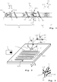
- Fig. 1 shows a dispersion channel 11 and a detection channel 12 which are integrally formed.
- Dispersion channel 11 has a first dispersion channel inlet 111, a second dispersion channel inlet 112, and a dispersion channel outlet 113.
- Second dispersion channel inlet 112 is arranged downstream of first dispersion channel inlet 111
- dispersion channel outlet 113 is arranged downstream of first and second dispersion channel inlets 111, 112.
- Detection channel 12 has a detection channel inlet 121 which is identical with dispersion channel outlet 113, and two further detection channel inlets 122, 123.
- a buffer liquid 2 is introduced into dispersion channel 11 through first dispersion channel inlet 111 with the aid of a pump 1 (see Fig. 2 ), and the parabolic velocity profile of the laminar flow of buffer liquid 2 flowing through dispersion channel 11 is indicated by the arrows.
- a candidate substance injector 7 is arranged at second dispersion channel inlet 112 to introduce a soluble candidate substance into the laminar flow of buffer liquid 2 flowing through dispersion channel 11.
- the soluble candidate substance is a soluble candidate substance capable of inhibiting the activity of a converting enzyme.
- the soluble candidate substance solves in the buffer liquid 2 to form a candidate substance solute 3 in the buffer liquid 2 having an initial concentration profile schematically indicated by the rectangular profile 31 depicted above second dispersion channel inlet, although the actual initial concentration profile is not rectangular as shown.
- the initial concentration profile 31 is then dispersed by Taylor-Aris-dispersion caused by the laminar flow of buffer liquid 2 through the dispersion channel 11 so that the initial concentration profile 31 changes into a dispersed concentration profile indicated by Gaussian curve 32 depicted above the outlet 113 of dispersion channel 11.
- Buffer liquid 2 containing the dispersed concentration profile 32 is then directed into detection channel 12 through the inlet 121 of detection channel 12 which in the embodiment shown is identical with the outlet 113 of dispersion channel 11, since dispersion channel 11 and detection channel 12 are integrally formed so that the inner wall 13 of dispersion channel 11 at dispersion channel outlet 113 and the inner wall 14 of detection channel 12 at detection channel inlet 121 are of the same size and shape to provide for a continuous inner channel wall at the connection of dispersion channel 11 and detection channel 12.
- Detection channel 12 comprises two further detection channel inlets 122, 123 which are arranged at the connection of dispersion channel 11 to detection channel 12.
- Two target components 41, 42 are separately introduced through the two further detection channel inlets 122, 123 with the aid of two target injectors 8, 9 (see Fig. 2 ).
- the flow of buffer liquid 2 as well as the flows of the combined target comprising the two target components 41, 42 are continuously supplied before the soluble candidate substance is introduced into dispersion channel 11.
- This provides for a constant concentration of the combined target comprising the two components 41, 42 in detection channel 12.
- This constant profile of the combined target overlies the final symmetrical concentration profile 33 of the candidate substance solute 3 in the detection channel 12 to form a combined concentration profile comprising the constant target concentration profile overlying the final symmetrical concentration profile 33 of the candidate substance solute.
- a combined target comprising two components 41, 42 allows for carrying out specific biological assays with combined targets.
- a combined target may comprise, for example, an enzyme 41 and a component 42 to be converted by the enzyme.
- the enzymatic activity as the biological response can be determined by detecting the conversion rate of component 42. If the candidate substance is an enzyme inhibitor inhibiting the conversion activity of enzyme 41, a decrease in enzyme activity would have to be the biological response.
- the biological response may be detected in the present example by optically detecting a fluorescent signal emitted by a fluorescent marker comprised by the component 42. Conversion of the component 42 by the enzyme results in a decrease in intensity of the detected fluorescent signal (an increase may be detected in assays based on quenching effects). This decrease in the detected fluorescent signal is a consequence of the enzyme activity.
- the candidate substance is an enzyme inhibitor inhibiting the enzyme to convert the component 42
- the detected fluorescent signal from the component 42 would either not decrease at all or only decrease to a lesser extent.
- the optically detected signal representative of the biological response is the change in intensity of the fluorescent light emitted by the fluorescent marker comprised by the component 42.
- This reduced decrease in intensity can be determined over the at least one half of the combined concentration profile held in the detection channel 12. Since the at least one half of the combined concentration profile comprises continuous "dilutions" over the at least one half of the combined concentration profile (different concentrations of the candidate substance solute 3 in the buffer liquid spanning ideally the entire range of concentrations between zero and the initial concentration, however, at least about five to six orders of magnitude), the dilution assay allows for determining the biological response over the entire range at practically all concentrations of the candidate substance solute 3 contained in the combined concentration profile.
- the fluorescent light may be detected along the channel by means of a CCD camera 6 (see Fig. 2 ) as an optical detection unit.
- the CCD camera detects the intensity of the fluorescent light at different detection locations of the detection channel 12 relative to the CCD camera 6.
- Fig. 2 An embodiment of the system according to the invention is shown in Fig. 2 .
- the system may be used for example, to carry out the method described above in connection with Fig. 1 .
- a portion of the dispersion channel 11 and detection channel 12 are arranged on a chip 5.
- Chip 5 is movably arranged to allow for changing the position of various portions of the detection channel 12 relative to the CCD camera 6 as optical detection unit.
- Only a portion of dispersion channel 11 is arranged on chip 5 while dispersion channel 11 also comprises a capillary 114 to extend the length of dispersion channel to provide for sufficient dispersion of the initial concentration profile 31 due to Taylor-Aris-dispersion.
- Pump 1 is arranged at dispersion channel inlet 111 for pumping buffer liquid into dispersion channel 11 and to cause a laminar flow therethrough.
- Second dispersion channel inlet 112 is arranged downstream of first dispersion channel inlet 111 where the soluble candidate substance is introduced into the buffer liquid with the aid of candidate substance injector 7.
- a laminar flow is generated both through capillary 114 and the on-chip portion of dispersion channel 11, as has been explained above, dispersing the initial profile of the candidate substance solute represented by rectangular curve 31 by Taylor-Aris-dispersion into the dispersed profile represented by Gaussian curve 32 (see Fig. 1 ).
- Dispersion channel outlet 113 as well as the two further detection channel inlets 122, 123 are arranged on chip 5.
- the two further detection channel inlets 122, 123 merge with first detection channel inlet 121 which is identical to dispersion channel outlet 113 (see Fig. 3 ).
- Detection channel 12 comprises a meander-shaped portion 124 arranged on chip 5.
- a detection channel outlet 125 is arranged at the end of detection channel 12 for draining the buffer liquid from detection channel 12.
Landscapes
- Health & Medical Sciences (AREA)
- Chemical & Material Sciences (AREA)
- Life Sciences & Earth Sciences (AREA)
- Immunology (AREA)
- Engineering & Computer Science (AREA)
- General Health & Medical Sciences (AREA)
- Analytical Chemistry (AREA)
- Molecular Biology (AREA)
- Physics & Mathematics (AREA)
- Hematology (AREA)
- Biochemistry (AREA)
- Biomedical Technology (AREA)
- Organic Chemistry (AREA)
- Urology & Nephrology (AREA)
- Pathology (AREA)
- General Physics & Mathematics (AREA)
- Biotechnology (AREA)
- Microbiology (AREA)
- Zoology (AREA)
- Wood Science & Technology (AREA)
- Proteomics, Peptides & Aminoacids (AREA)
- Chemical Kinetics & Catalysis (AREA)
- Cell Biology (AREA)
- Food Science & Technology (AREA)
- Medicinal Chemistry (AREA)
- Nuclear Medicine, Radiotherapy & Molecular Imaging (AREA)
- Clinical Laboratory Science (AREA)
- Biophysics (AREA)
- Dispersion Chemistry (AREA)
- Genetics & Genomics (AREA)
- Bioinformatics & Cheminformatics (AREA)
- General Engineering & Computer Science (AREA)
- Optics & Photonics (AREA)
- Investigating Or Analysing Materials By Optical Means (AREA)
- Investigating Or Analysing Biological Materials (AREA)
- Measurement Of The Respiration, Hearing Ability, Form, And Blood Characteristics Of Living Organisms (AREA)
- Apparatus Associated With Microorganisms And Enzymes (AREA)
- Investigating, Analyzing Materials By Fluorescence Or Luminescence (AREA)
- Measuring Or Testing Involving Enzymes Or Micro-Organisms (AREA)
Claims (13)
- Procédé pour la détermination d'une réponse biologique d'une cible (41 ; 41, 42) à une substance candidate soluble, le procédé comprenant les étapes suivants:- introduire une substance candidate soluble dans un flux laminaire d'un liquide tampon (2) s'écoulant le long d'un canal de dispersion (11), pour la formation d'un produit de dissolution de la substance candidate (3) dans le liquide tampon (2) ayant un profil de concentration initial (31) ;- disperser par le flux laminaire du liquide tampon (2) le long du canal de dispersion (11) le profil de concentration initial (31) du produit de dissolution de la substance candidate (3) dans le liquide tampon (2) pour la formation d'un profil de concentration dispersé (32) du produit de dissolution de la substance candidate (3) dans le liquide tampon (2) ;- diriger le flux laminaire du liquide tampon (2), contenant le produit de dissolution de la substance candidate (3) ayant le profil de concentration dispersé (32), dans un canal de détection (12) pour la formation d'un profil de concentration symétrique final (33) du produit de dissolution de la substance candidate (3) dans le liquide tampon (2) dans le canal de détection (12) ;- introduire une cible dans le canal de détection (12) (41 ; 41, 42) de manière à obtenir un profil de concentration combiné dans le liquide tampon (2), le profil de concentration combiné comprenant un profil de concentration constant de la cible superposant le profil de concentration symétrique final (33) du produit de dissolution de la substance candidate (3) ;- retenir dans le canal de détection (12) au moins une moitié du profil de concentration combiné contenu dans le liquide tampon ; et- balayer optiquement ladite au moins une moitié du profil de concentration combiné contenu dans le liquide tampon, retenue dans le canal de détection (12), pour détecter aux diverses concentrations du produit de dissolution de la substance candidate (3) du profil de concentration combiné un signal optique qui est représentatif de la réponse biologique de la cible (41 ; 41, 42) à la substance candidate soluble.
- Procédé selon la revendication 1, dans lequel l'étape de retenue dans le canal de détection (12) de ladite au moins une moitié du profil de concentration combiné contenu dans le liquide tampon (2) est effectuée par arrêt de la poursuite de l'introduction de liquide tampon (2) dans le canal de dispersion (11) et de cible dans le canal de détection.
- Procédé selon l'une quelconque des revendications 1 et 2, dans lequel le flux laminaire du liquide tampon (2) contenant le produit de dissolution de la substance candidate (3) ayant le profil de concentration dispersé (32) est dirigé dans le canal de détection (12) à un débit constant, et dans lequel la cible (41 ; 41, 42) est introduite dans le canal de détection (12) à un débit constant pour l'obtention du profil de concentration combiné comprenant le profil de concentration constant de la cible (41 ; 41, 42) superposant le profil de concentration symétrique final du produit de dissolution de la substance candidate (3) dans le liquide tampon (2).
- Procédé selon l'une quelconque des revendications précédentes, dans lequel l'étape de maintien dans le canal de détection (12) d'au moins une moitié du profil de concentration combiné contenu dans le liquide tampon (2) comprend le maintien de seulement une moitié du profil de concentration combiné (33) dans le canal de détection (12).
- Procédé selon la revendication 4, dans lequel ladite seulement une moitié du profil de concentration combiné (33) contient au moins cinq ordres de grandeur de la concentration du produit de dissolution de la substance candidate (3) dans le liquide tampon (2).
- Procédé selon l'une quelconque des revendications précédentes, dans lequel l'étape de balayage optique dans le canal de détection (12) de ladite au moins une moitié du profil de concentration combiné, contenu dans le liquide tampon (2), est effectuée par déplacement du canal de détection (12) par rapport à une unité de détection optique (6) en disposition stationnaire.
- Procédé selon la revendication 6, dans lequel l'étape de balayage optique dans le canal de détection (12) de ladite au moins une moitié du profil de concentration combiné contenu dans le liquide tampon (2) est effectuée par déplacement de façon répétée du canal de détection (12) dans la même plage de positions relatives du canal de détection (12) et de l'unité de détection optique (6), et dans lequel les signaux respectifs représentatifs des diverses réponses biologiques sont ensuite traités pour former un signal moyen ou une variation de signal dépendant du temps, représentatifs de la réponse biologique de la cible à la substance candidate soluble.
- Procédé selon l'une quelconque des revendications 6 et 7, dans lequel l'étape de balayage optique dans le canal de détection de ladite une moitié du profil de concentration combiné contenu dans le liquide tampon est effectuée à différentes sensibilités de détection par ajustement de la sensibilité de détection de l'unité de détection optique (6) au signal optique qui est représentatif de la réponse biologique de la cible (41 ; 41, 42) à la substance candidate soluble et/ou à un signal optique représentatif de la concentration de la substance candidate soluble.
- Procédé selon l'une quelconque des revendications précédentes, dans lequel la cible introduite dans le canal de détection (12) est une cible combinée comprenant au moins deux composants (41, 42) qui sont introduits séparément dans le canal de détection (12).
- Procédé selon l'une quelconque des revendications précédentes, dans lequel soit la substance candidate soluble formant le produit de dissolution de la substance candidate (3), soit la cible (41 ; 41, 42) ou les deux comprend (comprennent) un marqueur fluorescent, le marqueur fluorescent étant capable d'émettre un signal fluorescent détectable optiquement.
- Système pour la détermination d'une réponse biologique d'une cible 41 ; 41, 42) à une substance candidate soluble, le système comprenant- un canal de dispersion (11), le canal de dispersion (11) comportant
un premier orifice d'entrée (111) du canal de dispersion, pour l'introduction d'un liquide tampon (2) dans le canal de dispersion (11),
un deuxième orifice d'entrée (112) du canal de dispersion, disposé en aval du premier orifice d'entrée (111) du canal de dispersion, pour l'introduction d'une substance candidate soluble dans le liquide tampon (2) s'écoulant le long du canal de dispersion (11), pour la formation d'un produit de dissolution de la substance candidate (3) dans le liquide tampon (2), et
un orifice de sortie (113) du canal de dispersion, disposé en aval des premier et deuxième orifices d'entrée (111, 112) du canal de dispersion, pour permettre au liquide tampon (2) contenant le produit de dissolution de la substance candidate (3) de sortir du canal de dispersion (11),- une pompe (1) destinée à engendrer un flux laminaire de liquide tampon le long du canal de dispersion (11),- un injecteur (7) de substance candidate pour introduire la substance candidate soluble dans le flux laminaire de liquide tampon le long du canal de dispersion (11) pour la formation du produit de dissolution de la substance candidate (3) dans le liquide tampon (2), ayant un profil de concentration initial, qui est ensuite dispersé par le flux laminaire du liquide tampon (2) le long du canal de dispersion (11) pour former un profil de concentration dispersé du produit de dissolution de la substance candidate (3) dans le liquide tampon (2),- un canal de détection (12), le canal de détection (12) comportant
un premier orifice d'entrée (121) du canal de détection, qui est disposé en communication fluidique avec l'orifice de sortie (113) du canal de dispersion, de sorte que le flux laminaire du liquide tampon (2) sortant du canal de dispersion (11) par l'orifice de sortie (113) du canal de dispersion et comportant le profil de concentration dispersé du produit de dissolution de la substance candidate (3) est dirigé, via le premier orifice d'entrée (121) du canal de détection, dans le canal de détection (12) pour former un profil de concentration final symétrique du produit de dissolution de la substance candidate (3) dans le liquide tampon, dans le canal de détection (12), et
au moins un autre orifice d'entrée (122, 123) du canal de détection, pour l'introduction d'une cible (41 ; 41, 42) dans le canal de détection (12),- au moins un injecteur de cible (8, 9) pour l'introduction d'une cible dans le canal de détection (12) via ledit au moins un autre orifice d'entrée (122, 123) du canal de détection, de manière à obtenir un profil de concentration combiné comprenant un profil de concentration constant de la cible, superposant le profil de concentration final symétrique du produit de dissolution de la substance candidate (3) dans le liquide tampon (2),- un moyen pour le maintien dans le canal de détection (12) d'au moins une moitié du profil de concentration combiné contenu dans le liquide tampon (2), et- une unité de détection optique (6) capable de et disposée pour balayer optiquement ladite au moins une moitié du profil de concentration combiné, contenu dans le liquide tampon (2) dans le canal de détection (12), pour détecter, aux diverses concentrations du produit de dissolution de la substance candidate (3) du profil de concentration combiné, un signal optique représentatif de la réponse biologique de la cible à la substance candidate soluble,l'orifice de sortie (113) du canal de dispersion et le premier orifice d'entrée (121) du canal de détection communiquant l'un avec l'autre de manière à maintenir le flux laminaire à la connexion de ces canaux et dans le canal de détection (12). - Système selon la revendication 11, dans lequel une paroi interne (13) du canal de dispersion (11) au niveau de l'orifice de sortie (113) du canal de dispersion et une paroi interne (14) du canal de détection (12) au niveau du premier orifice d'entrée (121) du canal de détection sont de la même forme et de mêmes dimensions pour produire un contour continu de paroi interne de canal au niveau de la connexion du canal de dispersion (11) et du canal de détection (12).
- Système selon la revendication 12, dans lequel la paroi interne (13) du canal de dispersion (11) au niveau de l'orifice de sortie (113) du canal de dispersion et la paroi interne (14) du canal de détection (12) au niveau de l'orifice d'entrée (121) du canal de détection sont solidaires de manière à former une paroi interne commune (13, 14) continue.
Priority Applications (1)
| Application Number | Priority Date | Filing Date | Title |
|---|---|---|---|
| EP14709591.3A EP2965082B1 (fr) | 2013-03-05 | 2014-03-04 | Procédé et système pour déterminer une réponse biologique d'une cible à une substance candidate soluble |
Applications Claiming Priority (3)
| Application Number | Priority Date | Filing Date | Title |
|---|---|---|---|
| EP13157877 | 2013-03-05 | ||
| EP14709591.3A EP2965082B1 (fr) | 2013-03-05 | 2014-03-04 | Procédé et système pour déterminer une réponse biologique d'une cible à une substance candidate soluble |
| PCT/EP2014/054117 WO2014135512A1 (fr) | 2013-03-05 | 2014-03-04 | Procédé et système de détermination d'une réponse biologique d'une cible à une substance candidate soluble |
Publications (2)
| Publication Number | Publication Date |
|---|---|
| EP2965082A1 EP2965082A1 (fr) | 2016-01-13 |
| EP2965082B1 true EP2965082B1 (fr) | 2016-12-28 |
Family
ID=47832965
Family Applications (1)
| Application Number | Title | Priority Date | Filing Date |
|---|---|---|---|
| EP14709591.3A Active EP2965082B1 (fr) | 2013-03-05 | 2014-03-04 | Procédé et système pour déterminer une réponse biologique d'une cible à une substance candidate soluble |
Country Status (11)
| Country | Link |
|---|---|
| US (1) | US9797891B2 (fr) |
| EP (1) | EP2965082B1 (fr) |
| JP (1) | JP6403074B2 (fr) |
| KR (1) | KR20150125000A (fr) |
| CN (1) | CN105264378B (fr) |
| BR (1) | BR112015019461A2 (fr) |
| CA (1) | CA2902786A1 (fr) |
| ES (1) | ES2617681T3 (fr) |
| MX (1) | MX358153B (fr) |
| RU (1) | RU2671974C2 (fr) |
| WO (1) | WO2014135512A1 (fr) |
Families Citing this family (5)
| Publication number | Priority date | Publication date | Assignee | Title |
|---|---|---|---|---|
| FR3065885B1 (fr) * | 2017-05-03 | 2021-12-17 | Commissariat Energie Atomique | Systeme de melange microfluidique comprenant un injecteur commande pour effectuer un melange avec une dispersion de type taylor aris |
| CN109799220B (zh) * | 2018-12-21 | 2021-03-26 | 中国科学院合肥物质科学研究院 | 基于金属螯合物拉曼标签技术检测组织液中组胺的方法 |
| WO2021180289A1 (fr) | 2020-03-11 | 2021-09-16 | Fida Biosystems Aps | Procédé, appareil, ensemble et système appropriés pour déterminer une propriété caractéristique d'une interaction moléculaire |
| CN112473757B (zh) * | 2020-11-19 | 2021-12-17 | 江南大学 | 一种用于食品安全快速检测的微流控芯片检测系统 |
| KR102836699B1 (ko) * | 2021-11-18 | 2025-07-21 | 한국과학기술원 | 표적 물질의 디지털 분석 방법 및 이를 이용한 디바이스 |
Family Cites Families (17)
| Publication number | Priority date | Publication date | Assignee | Title |
|---|---|---|---|---|
| DE69636391D1 (de) * | 1995-09-06 | 2006-09-07 | Icos Corp | Zellzikluskontrollpunkt-spezifische gene |
| US6586193B2 (en) * | 1996-04-25 | 2003-07-01 | Genicon Sciences Corporation | Analyte assay using particulate labels |
| US20040053315A1 (en) | 2002-08-12 | 2004-03-18 | Caliper Technologies Corp. | Methods and systems for monitoring molecular interactions |
| WO2004059299A1 (fr) * | 2002-12-16 | 2004-07-15 | Cytodiscovery, Inc. | Systeme microfluidique avec membrane permeable integree |
| US7039527B2 (en) | 2003-10-01 | 2006-05-02 | Caliper Life Sciences, Inc. | Method for measuring diffusivities of compounds using microchips |
| TW200537094A (en) * | 2004-05-11 | 2005-11-16 | Shi-Ping Liu | Gaseous chemical biological exposure chamber |
| JP2007044041A (ja) * | 2005-07-13 | 2007-02-22 | Mitsubishi Chemicals Corp | Scrapperタンパク質を利用した医薬候補物質のスクリーニング方法 |
| JP4273425B2 (ja) * | 2005-09-28 | 2009-06-03 | 独立行政法人産業技術総合研究所 | マイクロ流路利用分子分析方法 |
| JP2007268491A (ja) * | 2006-03-31 | 2007-10-18 | Fujifilm Corp | マイクロデバイス及びそれを用いた触媒反応方法 |
| KR100940598B1 (ko) | 2007-10-12 | 2010-02-04 | 부산대학교 산학협력단 | Dna검출용 마이크로칩 및 이를 이용한 검출방법 |
| US7813882B2 (en) | 2008-02-29 | 2010-10-12 | Wyatt Technology Corporation | Method for determining average properties of molecules in solution |
| EP2485830A2 (fr) * | 2009-10-08 | 2012-08-15 | Universite De Strasbourg | Appareil et procédé pour générer une concentration variable de soluté dans des microgouttelettes |
| JP5881031B2 (ja) * | 2010-03-18 | 2016-03-09 | 国立研究開発法人産業技術総合研究所 | 薬剤感受性試験用バイオチップ |
| JP6170431B2 (ja) * | 2010-09-29 | 2017-07-26 | マサチューセッツ インスティテュート オブ テクノロジー | 細胞間相互作用のハイスループット研究のためのデバイス |
| EP2656048B1 (fr) * | 2010-12-23 | 2020-11-25 | Molecular Devices, LLC | Procédés d'injection par dispersion pour des applications de biodétection |
| FR2972117B1 (fr) * | 2011-03-04 | 2013-12-20 | Centre Nat Rech Scient | Systeme microfluidique pour controler un profil de concentration de molecules susceptibles de stimuler une cible |
| CN102586394B (zh) * | 2012-02-28 | 2014-01-01 | 中国科学院微生物研究所 | 一种筛选以神经酰胺糖脂为作用靶标的抗真菌物质的方法 |
-
2014
- 2014-03-04 MX MX2015011369A patent/MX358153B/es active IP Right Grant
- 2014-03-04 EP EP14709591.3A patent/EP2965082B1/fr active Active
- 2014-03-04 CN CN201480012524.0A patent/CN105264378B/zh not_active Expired - Fee Related
- 2014-03-04 ES ES14709591.3T patent/ES2617681T3/es active Active
- 2014-03-04 KR KR1020157027334A patent/KR20150125000A/ko not_active Abandoned
- 2014-03-04 WO PCT/EP2014/054117 patent/WO2014135512A1/fr not_active Ceased
- 2014-03-04 BR BR112015019461A patent/BR112015019461A2/pt not_active IP Right Cessation
- 2014-03-04 RU RU2015139400A patent/RU2671974C2/ru not_active IP Right Cessation
- 2014-03-04 US US14/771,437 patent/US9797891B2/en not_active Expired - Fee Related
- 2014-03-04 CA CA2902786A patent/CA2902786A1/fr not_active Abandoned
- 2014-03-04 JP JP2015560656A patent/JP6403074B2/ja not_active Expired - Fee Related
Non-Patent Citations (1)
| Title |
|---|
| None * |
Also Published As
| Publication number | Publication date |
|---|---|
| JP2016509233A (ja) | 2016-03-24 |
| CN105264378B (zh) | 2017-05-24 |
| MX358153B (es) | 2018-08-07 |
| CN105264378A (zh) | 2016-01-20 |
| WO2014135512A1 (fr) | 2014-09-12 |
| ES2617681T3 (es) | 2017-06-19 |
| CA2902786A1 (fr) | 2014-09-12 |
| EP2965082A1 (fr) | 2016-01-13 |
| BR112015019461A2 (pt) | 2017-07-18 |
| MX2015011369A (es) | 2015-12-16 |
| JP6403074B2 (ja) | 2018-10-10 |
| US9797891B2 (en) | 2017-10-24 |
| HK1213995A1 (zh) | 2016-07-15 |
| RU2671974C2 (ru) | 2018-11-08 |
| US20160011180A1 (en) | 2016-01-14 |
| RU2015139400A (ru) | 2017-04-07 |
| KR20150125000A (ko) | 2015-11-06 |
Similar Documents
| Publication | Publication Date | Title |
|---|---|---|
| US9797891B2 (en) | Method and system for determining a biological response of a target to a soluble candidate substance | |
| US8502169B2 (en) | Device for the exalted detection of the emission of a target particle | |
| Mukunda et al. | Light emitting diodes (LEDs) in fluorescence-based analytical applications: A review | |
| Go¨ sch et al. | Parallel single molecule detection with a fully integrated single-photon 2× 2 CMOS detector array | |
| US9488571B2 (en) | Two-dimensional spectral imaging system | |
| US8313904B2 (en) | Biological analysis arrangement and approach therefor | |
| US7817273B2 (en) | Two-dimensional spectral imaging system | |
| BRPI0714458A2 (pt) | sistema de detecÇço para detectar locais de luminescÊncia sobre um substrato, compensador àptico, mÉtodo para detectar locais de radiaÇço sobre um substrato, mÉtodo baseado em computador para projetar um compensador àptico, produto de programa de computador, dispositivo de armazenagem de dados legÍveis por mÁquina, e, transmissço do produto de programa de computador | |
| JP2002507762A (ja) | 共焦点顕微鏡イメージングシステム | |
| EP3320567B1 (fr) | Dispositif de détection optique, son procédé de fonctionnement et programme informatique | |
| CN101206216B (zh) | 低聚物探针阵列芯片、用于制造其的掩模以及使用其的杂交分析方法 | |
| Ingargiola et al. | 8-spot smFRET analysis using two 8-pixel SPAD arrays | |
| Kornienko et al. | Miniaturization of whole live cell-based GPCR assays using microdispensing and detection systems | |
| O'Driscoll et al. | A novel camera phone-based platform for quantitative fluorescence sensing | |
| US20110275538A1 (en) | Measurement of biological targets | |
| Gomez-Hens et al. | Modern analytical approaches to high-throughput drug discovery | |
| US7956990B2 (en) | Biochip, biochip reader and biochip reading method | |
| HK1213995B (en) | Method and system for determining a biological response of a target to a soluble candidate substance | |
| US20070147727A1 (en) | Optical waveguide bio-sensing device | |
| US20020182111A1 (en) | Method and apparatus for visible spectrum imaging | |
| JP4967261B2 (ja) | プローブ担体 | |
| Huang et al. | Handheld fluorescence test strip reader for rapid on-site biochemical detection | |
| Zemanová et al. | High-Throughput Screening of Interactions Between G ProteinCoupled Receptors and Ligands Using Confocal Optics Microscopy | |
| Jin | Development of biosensor based on imaging ellipsometry and its applications | |
| Power | Buyer’s Guide |
Legal Events
| Date | Code | Title | Description |
|---|---|---|---|
| PUAI | Public reference made under article 153(3) epc to a published international application that has entered the european phase |
Free format text: ORIGINAL CODE: 0009012 |
|
| 17P | Request for examination filed |
Effective date: 20150930 |
|
| AK | Designated contracting states |
Kind code of ref document: A1 Designated state(s): AL AT BE BG CH CY CZ DE DK EE ES FI FR GB GR HR HU IE IS IT LI LT LU LV MC MK MT NL NO PL PT RO RS SE SI SK SM TR |
|
| AX | Request for extension of the european patent |
Extension state: BA ME |
|
| DAX | Request for extension of the european patent (deleted) | ||
| GRAP | Despatch of communication of intention to grant a patent |
Free format text: ORIGINAL CODE: EPIDOSNIGR1 |
|
| INTG | Intention to grant announced |
Effective date: 20160714 |
|
| GRAS | Grant fee paid |
Free format text: ORIGINAL CODE: EPIDOSNIGR3 |
|
| GRAA | (expected) grant |
Free format text: ORIGINAL CODE: 0009210 |
|
| AK | Designated contracting states |
Kind code of ref document: B1 Designated state(s): AL AT BE BG CH CY CZ DE DK EE ES FI FR GB GR HR HU IE IS IT LI LT LU LV MC MK MT NL NO PL PT RO RS SE SI SK SM TR |
|
| REG | Reference to a national code |
Ref country code: GB Ref legal event code: FG4D |
|
| REG | Reference to a national code |
Ref country code: CH Ref legal event code: EP |
|
| REG | Reference to a national code |
Ref country code: AT Ref legal event code: REF Ref document number: 857753 Country of ref document: AT Kind code of ref document: T Effective date: 20170115 |
|
| REG | Reference to a national code |
Ref country code: IE Ref legal event code: FG4D |
|
| REG | Reference to a national code |
Ref country code: CH Ref legal event code: NV Representative=s name: BOHEST AG, CH |
|
| REG | Reference to a national code |
Ref country code: DE Ref legal event code: R096 Ref document number: 602014005851 Country of ref document: DE |
|
| REG | Reference to a national code |
Ref country code: FR Ref legal event code: PLFP Year of fee payment: 4 |
|
| PG25 | Lapsed in a contracting state [announced via postgrant information from national office to epo] |
Ref country code: LV Free format text: LAPSE BECAUSE OF FAILURE TO SUBMIT A TRANSLATION OF THE DESCRIPTION OR TO PAY THE FEE WITHIN THE PRESCRIBED TIME-LIMIT Effective date: 20161228 |
|
| REG | Reference to a national code |
Ref country code: LT Ref legal event code: MG4D |
|
| PG25 | Lapsed in a contracting state [announced via postgrant information from national office to epo] |
Ref country code: LT Free format text: LAPSE BECAUSE OF FAILURE TO SUBMIT A TRANSLATION OF THE DESCRIPTION OR TO PAY THE FEE WITHIN THE PRESCRIBED TIME-LIMIT Effective date: 20161228 Ref country code: SE Free format text: LAPSE BECAUSE OF FAILURE TO SUBMIT A TRANSLATION OF THE DESCRIPTION OR TO PAY THE FEE WITHIN THE PRESCRIBED TIME-LIMIT Effective date: 20161228 Ref country code: GR Free format text: LAPSE BECAUSE OF FAILURE TO SUBMIT A TRANSLATION OF THE DESCRIPTION OR TO PAY THE FEE WITHIN THE PRESCRIBED TIME-LIMIT Effective date: 20170329 Ref country code: NO Free format text: LAPSE BECAUSE OF FAILURE TO SUBMIT A TRANSLATION OF THE DESCRIPTION OR TO PAY THE FEE WITHIN THE PRESCRIBED TIME-LIMIT Effective date: 20170328 |
|
| REG | Reference to a national code |
Ref country code: NL Ref legal event code: MP Effective date: 20161228 |
|
| REG | Reference to a national code |
Ref country code: AT Ref legal event code: MK05 Ref document number: 857753 Country of ref document: AT Kind code of ref document: T Effective date: 20161228 |
|
| PG25 | Lapsed in a contracting state [announced via postgrant information from national office to epo] |
Ref country code: FI Free format text: LAPSE BECAUSE OF FAILURE TO SUBMIT A TRANSLATION OF THE DESCRIPTION OR TO PAY THE FEE WITHIN THE PRESCRIBED TIME-LIMIT Effective date: 20161228 Ref country code: RS Free format text: LAPSE BECAUSE OF FAILURE TO SUBMIT A TRANSLATION OF THE DESCRIPTION OR TO PAY THE FEE WITHIN THE PRESCRIBED TIME-LIMIT Effective date: 20161228 Ref country code: HR Free format text: LAPSE BECAUSE OF FAILURE TO SUBMIT A TRANSLATION OF THE DESCRIPTION OR TO PAY THE FEE WITHIN THE PRESCRIBED TIME-LIMIT Effective date: 20161228 |
|
| REG | Reference to a national code |
Ref country code: ES Ref legal event code: FG2A Ref document number: 2617681 Country of ref document: ES Kind code of ref document: T3 Effective date: 20170619 |
|
| PG25 | Lapsed in a contracting state [announced via postgrant information from national office to epo] |
Ref country code: NL Free format text: LAPSE BECAUSE OF FAILURE TO SUBMIT A TRANSLATION OF THE DESCRIPTION OR TO PAY THE FEE WITHIN THE PRESCRIBED TIME-LIMIT Effective date: 20161228 |
|
| PG25 | Lapsed in a contracting state [announced via postgrant information from national office to epo] |
Ref country code: CZ Free format text: LAPSE BECAUSE OF FAILURE TO SUBMIT A TRANSLATION OF THE DESCRIPTION OR TO PAY THE FEE WITHIN THE PRESCRIBED TIME-LIMIT Effective date: 20161228 Ref country code: EE Free format text: LAPSE BECAUSE OF FAILURE TO SUBMIT A TRANSLATION OF THE DESCRIPTION OR TO PAY THE FEE WITHIN THE PRESCRIBED TIME-LIMIT Effective date: 20161228 Ref country code: SK Free format text: LAPSE BECAUSE OF FAILURE TO SUBMIT A TRANSLATION OF THE DESCRIPTION OR TO PAY THE FEE WITHIN THE PRESCRIBED TIME-LIMIT Effective date: 20161228 Ref country code: RO Free format text: LAPSE BECAUSE OF FAILURE TO SUBMIT A TRANSLATION OF THE DESCRIPTION OR TO PAY THE FEE WITHIN THE PRESCRIBED TIME-LIMIT Effective date: 20161228 Ref country code: IS Free format text: LAPSE BECAUSE OF FAILURE TO SUBMIT A TRANSLATION OF THE DESCRIPTION OR TO PAY THE FEE WITHIN THE PRESCRIBED TIME-LIMIT Effective date: 20170428 |
|
| PG25 | Lapsed in a contracting state [announced via postgrant information from national office to epo] |
Ref country code: BE Free format text: LAPSE BECAUSE OF FAILURE TO SUBMIT A TRANSLATION OF THE DESCRIPTION OR TO PAY THE FEE WITHIN THE PRESCRIBED TIME-LIMIT Effective date: 20161228 Ref country code: BG Free format text: LAPSE BECAUSE OF FAILURE TO SUBMIT A TRANSLATION OF THE DESCRIPTION OR TO PAY THE FEE WITHIN THE PRESCRIBED TIME-LIMIT Effective date: 20170328 Ref country code: PL Free format text: LAPSE BECAUSE OF FAILURE TO SUBMIT A TRANSLATION OF THE DESCRIPTION OR TO PAY THE FEE WITHIN THE PRESCRIBED TIME-LIMIT Effective date: 20161228 Ref country code: AT Free format text: LAPSE BECAUSE OF FAILURE TO SUBMIT A TRANSLATION OF THE DESCRIPTION OR TO PAY THE FEE WITHIN THE PRESCRIBED TIME-LIMIT Effective date: 20161228 Ref country code: SM Free format text: LAPSE BECAUSE OF FAILURE TO SUBMIT A TRANSLATION OF THE DESCRIPTION OR TO PAY THE FEE WITHIN THE PRESCRIBED TIME-LIMIT Effective date: 20161228 Ref country code: PT Free format text: LAPSE BECAUSE OF FAILURE TO SUBMIT A TRANSLATION OF THE DESCRIPTION OR TO PAY THE FEE WITHIN THE PRESCRIBED TIME-LIMIT Effective date: 20170428 |
|
| REG | Reference to a national code |
Ref country code: DE Ref legal event code: R097 Ref document number: 602014005851 Country of ref document: DE |
|
| PLBE | No opposition filed within time limit |
Free format text: ORIGINAL CODE: 0009261 |
|
| STAA | Information on the status of an ep patent application or granted ep patent |
Free format text: STATUS: NO OPPOSITION FILED WITHIN TIME LIMIT |
|
| PG25 | Lapsed in a contracting state [announced via postgrant information from national office to epo] |
Ref country code: DK Free format text: LAPSE BECAUSE OF FAILURE TO SUBMIT A TRANSLATION OF THE DESCRIPTION OR TO PAY THE FEE WITHIN THE PRESCRIBED TIME-LIMIT Effective date: 20161228 Ref country code: MC Free format text: LAPSE BECAUSE OF FAILURE TO SUBMIT A TRANSLATION OF THE DESCRIPTION OR TO PAY THE FEE WITHIN THE PRESCRIBED TIME-LIMIT Effective date: 20161228 |
|
| 26N | No opposition filed |
Effective date: 20170929 |
|
| REG | Reference to a national code |
Ref country code: IE Ref legal event code: MM4A |
|
| PG25 | Lapsed in a contracting state [announced via postgrant information from national office to epo] |
Ref country code: LU Free format text: LAPSE BECAUSE OF NON-PAYMENT OF DUE FEES Effective date: 20170304 |
|
| PG25 | Lapsed in a contracting state [announced via postgrant information from national office to epo] |
Ref country code: IE Free format text: LAPSE BECAUSE OF NON-PAYMENT OF DUE FEES Effective date: 20170304 Ref country code: SI Free format text: LAPSE BECAUSE OF FAILURE TO SUBMIT A TRANSLATION OF THE DESCRIPTION OR TO PAY THE FEE WITHIN THE PRESCRIBED TIME-LIMIT Effective date: 20161228 |
|
| REG | Reference to a national code |
Ref country code: FR Ref legal event code: PLFP Year of fee payment: 5 |
|
| PG25 | Lapsed in a contracting state [announced via postgrant information from national office to epo] |
Ref country code: MT Free format text: LAPSE BECAUSE OF NON-PAYMENT OF DUE FEES Effective date: 20170304 |
|
| PG25 | Lapsed in a contracting state [announced via postgrant information from national office to epo] |
Ref country code: HU Free format text: LAPSE BECAUSE OF FAILURE TO SUBMIT A TRANSLATION OF THE DESCRIPTION OR TO PAY THE FEE WITHIN THE PRESCRIBED TIME-LIMIT; INVALID AB INITIO Effective date: 20140304 |
|
| PG25 | Lapsed in a contracting state [announced via postgrant information from national office to epo] |
Ref country code: CY Free format text: LAPSE BECAUSE OF FAILURE TO SUBMIT A TRANSLATION OF THE DESCRIPTION OR TO PAY THE FEE WITHIN THE PRESCRIBED TIME-LIMIT Effective date: 20161228 |
|
| PG25 | Lapsed in a contracting state [announced via postgrant information from national office to epo] |
Ref country code: MK Free format text: LAPSE BECAUSE OF FAILURE TO SUBMIT A TRANSLATION OF THE DESCRIPTION OR TO PAY THE FEE WITHIN THE PRESCRIBED TIME-LIMIT Effective date: 20161228 |
|
| PGFP | Annual fee paid to national office [announced via postgrant information from national office to epo] |
Ref country code: GB Payment date: 20200317 Year of fee payment: 7 Ref country code: IT Payment date: 20200309 Year of fee payment: 7 |
|
| PGFP | Annual fee paid to national office [announced via postgrant information from national office to epo] |
Ref country code: CH Payment date: 20200311 Year of fee payment: 7 |
|
| PGFP | Annual fee paid to national office [announced via postgrant information from national office to epo] |
Ref country code: TR Payment date: 20200203 Year of fee payment: 7 Ref country code: FR Payment date: 20200226 Year of fee payment: 7 |
|
| PG25 | Lapsed in a contracting state [announced via postgrant information from national office to epo] |
Ref country code: AL Free format text: LAPSE BECAUSE OF FAILURE TO SUBMIT A TRANSLATION OF THE DESCRIPTION OR TO PAY THE FEE WITHIN THE PRESCRIBED TIME-LIMIT Effective date: 20161228 |
|
| PGFP | Annual fee paid to national office [announced via postgrant information from national office to epo] |
Ref country code: ES Payment date: 20200420 Year of fee payment: 7 Ref country code: DE Payment date: 20200514 Year of fee payment: 7 |
|
| REG | Reference to a national code |
Ref country code: DE Ref legal event code: R119 Ref document number: 602014005851 Country of ref document: DE |
|
| REG | Reference to a national code |
Ref country code: CH Ref legal event code: PL |
|
| GBPC | Gb: european patent ceased through non-payment of renewal fee |
Effective date: 20210304 |
|
| PG25 | Lapsed in a contracting state [announced via postgrant information from national office to epo] |
Ref country code: CH Free format text: LAPSE BECAUSE OF NON-PAYMENT OF DUE FEES Effective date: 20210331 Ref country code: LI Free format text: LAPSE BECAUSE OF NON-PAYMENT OF DUE FEES Effective date: 20210331 Ref country code: FR Free format text: LAPSE BECAUSE OF NON-PAYMENT OF DUE FEES Effective date: 20210331 Ref country code: GB Free format text: LAPSE BECAUSE OF NON-PAYMENT OF DUE FEES Effective date: 20210304 Ref country code: DE Free format text: LAPSE BECAUSE OF NON-PAYMENT OF DUE FEES Effective date: 20211001 |
|
| PG25 | Lapsed in a contracting state [announced via postgrant information from national office to epo] |
Ref country code: IT Free format text: LAPSE BECAUSE OF NON-PAYMENT OF DUE FEES Effective date: 20210304 |
|
| REG | Reference to a national code |
Ref country code: ES Ref legal event code: FD2A Effective date: 20220523 |
|
| PG25 | Lapsed in a contracting state [announced via postgrant information from national office to epo] |
Ref country code: ES Free format text: LAPSE BECAUSE OF NON-PAYMENT OF DUE FEES Effective date: 20210305 |