EP2965111B1 - System and method for channel information exchange for time of flight range determination - Google Patents
System and method for channel information exchange for time of flight range determination Download PDFInfo
- Publication number
- EP2965111B1 EP2965111B1 EP13877106.8A EP13877106A EP2965111B1 EP 2965111 B1 EP2965111 B1 EP 2965111B1 EP 13877106 A EP13877106 A EP 13877106A EP 2965111 B1 EP2965111 B1 EP 2965111B1
- Authority
- EP
- European Patent Office
- Prior art keywords
- ndp
- sta
- station
- tof
- sequence
- Prior art date
- Legal status (The legal status is an assumption and is not a legal conclusion. Google has not performed a legal analysis and makes no representation as to the accuracy of the status listed.)
- Active
Links
Images



Classifications
-
- H—ELECTRICITY
- H04—ELECTRIC COMMUNICATION TECHNIQUE
- H04W—WIRELESS COMMUNICATION NETWORKS
- H04W64/00—Locating users or terminals or network equipment for network management purposes, e.g. mobility management
-
- G—PHYSICS
- G01—MEASURING; TESTING
- G01S—RADIO DIRECTION-FINDING; RADIO NAVIGATION; DETERMINING DISTANCE OR VELOCITY BY USE OF RADIO WAVES; LOCATING OR PRESENCE-DETECTING BY USE OF THE REFLECTION OR RERADIATION OF RADIO WAVES; ANALOGOUS ARRANGEMENTS USING OTHER WAVES
- G01S13/00—Systems using the reflection or reradiation of radio waves, e.g. radar systems; Analogous systems using reflection or reradiation of waves whose nature or wavelength is irrelevant or unspecified
- G01S13/74—Systems using reradiation of radio waves, e.g. secondary radar systems; Analogous systems
- G01S13/76—Systems using reradiation of radio waves, e.g. secondary radar systems; Analogous systems wherein pulse-type signals are transmitted
- G01S13/765—Systems using reradiation of radio waves, e.g. secondary radar systems; Analogous systems wherein pulse-type signals are transmitted with exchange of information between interrogator and responder
-
- G—PHYSICS
- G01—MEASURING; TESTING
- G01S—RADIO DIRECTION-FINDING; RADIO NAVIGATION; DETERMINING DISTANCE OR VELOCITY BY USE OF RADIO WAVES; LOCATING OR PRESENCE-DETECTING BY USE OF THE REFLECTION OR RERADIATION OF RADIO WAVES; ANALOGOUS ARRANGEMENTS USING OTHER WAVES
- G01S13/00—Systems using the reflection or reradiation of radio waves, e.g. radar systems; Analogous systems using reflection or reradiation of waves whose nature or wavelength is irrelevant or unspecified
- G01S13/87—Combinations of radar systems, e.g. primary radar and secondary radar
- G01S13/878—Combination of several spaced transmitters or receivers of known location for determining the position of a transponder or a reflector
-
- G—PHYSICS
- G01—MEASURING; TESTING
- G01S—RADIO DIRECTION-FINDING; RADIO NAVIGATION; DETERMINING DISTANCE OR VELOCITY BY USE OF RADIO WAVES; LOCATING OR PRESENCE-DETECTING BY USE OF THE REFLECTION OR RERADIATION OF RADIO WAVES; ANALOGOUS ARRANGEMENTS USING OTHER WAVES
- G01S5/00—Position-fixing by co-ordinating two or more direction or position line determinations; Position-fixing by co-ordinating two or more distance determinations
- G01S5/02—Position-fixing by co-ordinating two or more direction or position line determinations; Position-fixing by co-ordinating two or more distance determinations using radio waves
- G01S5/0205—Details
- G01S5/0236—Assistance data, e.g. base station almanac
-
- G—PHYSICS
- G01—MEASURING; TESTING
- G01S—RADIO DIRECTION-FINDING; RADIO NAVIGATION; DETERMINING DISTANCE OR VELOCITY BY USE OF RADIO WAVES; LOCATING OR PRESENCE-DETECTING BY USE OF THE REFLECTION OR RERADIATION OF RADIO WAVES; ANALOGOUS ARRANGEMENTS USING OTHER WAVES
- G01S5/00—Position-fixing by co-ordinating two or more direction or position line determinations; Position-fixing by co-ordinating two or more distance determinations
- G01S5/02—Position-fixing by co-ordinating two or more direction or position line determinations; Position-fixing by co-ordinating two or more distance determinations using radio waves
- G01S5/0205—Details
- G01S5/0244—Accuracy or reliability of position solution or of measurements contributing thereto
-
- G—PHYSICS
- G01—MEASURING; TESTING
- G01S—RADIO DIRECTION-FINDING; RADIO NAVIGATION; DETERMINING DISTANCE OR VELOCITY BY USE OF RADIO WAVES; LOCATING OR PRESENCE-DETECTING BY USE OF THE REFLECTION OR RERADIATION OF RADIO WAVES; ANALOGOUS ARRANGEMENTS USING OTHER WAVES
- G01S5/00—Position-fixing by co-ordinating two or more direction or position line determinations; Position-fixing by co-ordinating two or more distance determinations
- G01S5/02—Position-fixing by co-ordinating two or more direction or position line determinations; Position-fixing by co-ordinating two or more distance determinations using radio waves
- G01S5/0284—Relative positioning
-
- G—PHYSICS
- G01—MEASURING; TESTING
- G01S—RADIO DIRECTION-FINDING; RADIO NAVIGATION; DETERMINING DISTANCE OR VELOCITY BY USE OF RADIO WAVES; LOCATING OR PRESENCE-DETECTING BY USE OF THE REFLECTION OR RERADIATION OF RADIO WAVES; ANALOGOUS ARRANGEMENTS USING OTHER WAVES
- G01S5/00—Position-fixing by co-ordinating two or more direction or position line determinations; Position-fixing by co-ordinating two or more distance determinations
- G01S5/02—Position-fixing by co-ordinating two or more direction or position line determinations; Position-fixing by co-ordinating two or more distance determinations using radio waves
- G01S5/10—Position of receiver fixed by co-ordinating a plurality of position lines defined by path-difference measurements, e.g. omega or decca systems
-
- G—PHYSICS
- G01—MEASURING; TESTING
- G01S—RADIO DIRECTION-FINDING; RADIO NAVIGATION; DETERMINING DISTANCE OR VELOCITY BY USE OF RADIO WAVES; LOCATING OR PRESENCE-DETECTING BY USE OF THE REFLECTION OR RERADIATION OF RADIO WAVES; ANALOGOUS ARRANGEMENTS USING OTHER WAVES
- G01S5/00—Position-fixing by co-ordinating two or more direction or position line determinations; Position-fixing by co-ordinating two or more distance determinations
- G01S5/02—Position-fixing by co-ordinating two or more direction or position line determinations; Position-fixing by co-ordinating two or more distance determinations using radio waves
- G01S5/14—Determining absolute distances from a plurality of spaced points of known location
-
- H—ELECTRICITY
- H04—ELECTRIC COMMUNICATION TECHNIQUE
- H04W—WIRELESS COMMUNICATION NETWORKS
- H04W4/00—Services specially adapted for wireless communication networks; Facilities therefor
- H04W4/02—Services making use of location information
- H04W4/023—Services making use of location information using mutual or relative location information between multiple location based services [LBS] targets or of distance thresholds
-
- G—PHYSICS
- G01—MEASURING; TESTING
- G01S—RADIO DIRECTION-FINDING; RADIO NAVIGATION; DETERMINING DISTANCE OR VELOCITY BY USE OF RADIO WAVES; LOCATING OR PRESENCE-DETECTING BY USE OF THE REFLECTION OR RERADIATION OF RADIO WAVES; ANALOGOUS ARRANGEMENTS USING OTHER WAVES
- G01S5/00—Position-fixing by co-ordinating two or more direction or position line determinations; Position-fixing by co-ordinating two or more distance determinations
- G01S5/02—Position-fixing by co-ordinating two or more direction or position line determinations; Position-fixing by co-ordinating two or more distance determinations using radio waves
- G01S5/06—Position of source determined by co-ordinating a plurality of position lines defined by path-difference measurements
-
- H—ELECTRICITY
- H04—ELECTRIC COMMUNICATION TECHNIQUE
- H04W—WIRELESS COMMUNICATION NETWORKS
- H04W84/00—Network topologies
- H04W84/02—Hierarchically pre-organised networks, e.g. paging networks, cellular networks, WLAN [Wireless Local Area Network] or WLL [Wireless Local Loop]
- H04W84/10—Small scale networks; Flat hierarchical networks
- H04W84/12—WLAN [Wireless Local Area Networks]
Definitions
- Examples of the present disclosure pertain to wireless network communications. Some Examples of the present disclosure relate to the IEEE 802.11 standards. Some examples of the present disclosure relate to WiFi networks. Some examples of the present disclosure relate to beamforming. Some examples of the present disclosure relate to channel feedback, location positioning, and time-of-flight (ToF).
- IEEE 802.11 standards.
- WiFi networks Some examples of the present disclosure relate to WiFi networks.
- beamforming Some examples of the present disclosure relate to channel feedback, location positioning, and time-of-flight (ToF).
- ToF time-of-flight
- GNSS global-navigation-satellite-systems
- GPS Global Positioning System
- GLONASS Russian Global Navigation Satellite System
- European GALILEO European GALILEO
- Time-of-Flight may be defined as the overall time a signal propagates from a mobile communication station (e.g., user) to an access point (AP) and back to the user. This value may then be converted into distance by dividing the time by two and multiplying the result by the speed of light.
- This method may be robust and scalable but may require hardware changes to the Wi-Fi modem.
- US 2012/032855 A1 discloses high-resolution ranging and location finding using multicarrier signals.
- Figure 4 and 6 do not fall within the scope of the appended independent claims.
- Figures 1 to 3 and 5 do not illustrate all the elements recited in the claims and/or also illustrate additional elements and/or show examples of how some elements of the claims could be implemented.
- WiFi communication systems and Institute of Electrical and Electronics Engineers (IEEE) 802.11 (i.e., a set of physical layer standards for implementing wireless local area network (WLAN) computer communication).
- IEEE Institute of Electrical and Electronics Engineers
- 802.11 i.e., a set of physical layer standards for implementing wireless local area network (WLAN) computer communication.
- WLAN wireless local area network
- present examples of the disclosure are not restricted to only a WiFi communication system or any particular communication standard.
- the present examples of the disclosure may be used in any communication system in which location and navigation capabilities may be desired.
- Time-of-Flight (ToF) positioning methods may provide a way to determine a mobile station's location in an environment where GNSS may not be available (e.g., indoors).
- Typical ToF methods may pose a barrier to entry since only those manufacturers having both navigation and WiFi technologies may implement this kind of solution.
- two wireless communication stations may calculate a time-of-arrival (ToA) independently in order to perform a WiFi distance measurement.
- Each station may combine a Time of Arrival (ToA) of a frame with the Time of Departure (ToD) of the frame in order to determine a round trip time between the stations. Multiplying the round trip time by the speed of light and dividing by two may result in a distance from a station.
- ToA Time of Arrival
- ToD Time of Departure
- the ToA calculation may be based on an analysis of channel information.
- the channel information refers to known channel properties of a communication link.
- the channel information may describe how a signal propagates from a transmitter to a receiver and may represent the combined effects of, for example, scattering, fading, and power decay with distance.
- the channel information may be described as a snapshot of the channel at a particular time, since the channel information may change as a mobile station moves about an area. Thus, new channel information may be used during each ToA calculation.
- the channel information for each channel may be determined by determining a distortion caused to a preamble of a frame transmitted over the channel.
- a preamble is illustrated in FIG. 3 and described subsequently. Since the expected preamble may be known by the receiver as a standard preamble and the preamble as actually received may be now known, the receiver can determine the channel information by the distortion caused to the expected preamble.
- Each station independently performing its own ToA analysis may introduce errors into the calculations due to only one side of the channel being taken into account. These errors may result in tens of meters of variation.
- a solution to this problem may be to have one station transfer its channel information to the other station.
- the ToF calculation may be offloaded to only one station to improve the quality of the range estimation.
- examples of the present disclosure provide a protocol to transfer the channel information from one side (e.g., a passive partner that only measures the channel information) to the other side (e.g., the "smart" partner) that may calculate the range estimation.
- Another advantage of this protocol may be the flexibility in choosing a type of offloading processing (e.g., from client to network, from network to client, or some combined method).
- the channel from the other side may be used to improve the quality of the range estimation by, for example: calculating a plurality of ToA hypotheses for each channel and select the best pair having the best likelihood of success, due to the physical channel nature where both channels are very similar, the two channels may be merged for an improved signal-to-noise ratio (SNR), or a combined estimation of range.
- SNR signal-to-noise ratio
- the channel information may be transferred to the other side of the channel by any one of a plurality of different methods. For example, the entire, uncompressed channel information may be transferred, the channel information may be compressed, the channel information may be decimated in frequency, or a list of hypotheses (with or without weighting) for potential ToA timings may be transferred.
- the present examples of the disclosure are not limited to just these channel information transfer methods.
- the present examples of the disclosure may allow a station (e.g., access point) that cannot handle multiple users with respect to inadequate processing power and/or memory for calculation of the ToA to offload most of the processing to other stations.
- a station e.g., access point
- low power devices e.g., mobile wireless stations
- FIG. 1 illustrates various network elements of a wireless communication network in accordance with some examples of the present disclosure.
- the wireless communication network includes one or more wireless communication stations 100, 102-104 that may include a mobile wireless station 100 and a plurality of access points (APs) 102-104 that may communicate over one or more wireless channels in accordance with IEEE 802.11 communication techniques.
- APs access points
- the mobile wireless station 100 may be a mobile communication device that is non-stationary.
- a communication device may include mobile radiotelephones, tablet computers, lap top computers, and other communication devices that may communicate with the access points 102-104 over one or more wireless channels using a communication technique (e.g., IEEE 802.11).
- a communication technique e.g., IEEE 802.11.
- the access points 102-104 may have fixed locations.
- the access points 102-104 may be part of a stationary network that may be coupled to a larger network (e.g., local area network (LAN), wide area network (WAN)).
- LAN local area network
- WAN wide area network
- the access points 102-104 may be part of a wired network that is coupled to the Internet.
- the mobile wireless station 100 may then access the larger network by communicating over the wireless channels with the access points 102-104.
- the mobile wireless station 100 may know its location with relation to the access points 102-104. Since the geographical locations of the access points 102-104 may be fixed and known, the geographical location of the mobile wireless station 100 may be determined by trilateration and tracked thereafter. The trilateration may be accomplished by using ToF calculations. In another example of the present disclosure, the access points 102-104 may be mobile and their location may be determined by GNSS or some other means.
- FIG. 2 is a functional block diagram of a wireless communication station in accordance with some examples of the present disclosure.
- Communication station 200 may be suitable for use as a mobile wireless communicator 100 ( FIG. 1 ) or any of the access points 102-104 ( FIG. 1 ), although other configurations may also be suitable.
- Communication station 200 may include physical layer circuitry 202 to communicate wirelessly with access points, mobile communication devices, and other communication stations over one or more antennas 205. Communication station 200 may also include processing circuitry 204 coupled to the physical layer circuitry 202 to perform other operations described herein.
- the physical layer circuitry 202 may be configured to transmit and receive ToF messages between communication stations.
- the physical layer circuitry 202 may also be configured to transmit and receive acknowledgments as well as other communications between communication stations.
- the physical layer circuitry 202 may be configured to modulate digital data from the processing circuitry 204 for transmission over a channel as well as demodulate received modulated signals into digital data for use by the processing circuitry 204.
- the processing circuitry 204 may be configured to calculate ToF measurements.
- the processing circuitry 204 may also be configured to calculate time intervals such as ToA and ToD.
- communication station 200 is illustrated as having several separate functional elements, one or more of the functional elements may be combined and may be implemented by combinations of software-configured elements, such as processing elements including digital signal processors (DSPs), and/or other hardware elements.
- processing elements including digital signal processors (DSPs), and/or other hardware elements.
- some elements may comprise one or more microprocessors, DSPs, field-programmable gate arrays (FPGAs), application specific integrated circuits (ASICs), radio-frequency integrated circuits (RFICs) and combinations of various hardware and logic circuitry for performing at least the functions described herein.
- the functional elements of communication station 200 may refer to one or more processes operating on one or more processing elements.
- communication station 200 may be part of a portable wireless communication device, such as a personal digital assistant (PDA), a laptop or portable computer with wireless communication capability, a web tablet, a wireless telephone, a smartphone, a wireless headset, a pager, an instant messaging device, a digital camera, an access point, a television, a medical device (e.g., a heart rate monitor, a blood pressure monitor, etc.), or other device that may receive and/or transmit information wirelessly.
- a communication station may include one or more of a keyboard, a display, a nonvolatile memory port, multiple antennas, a graphics processor, an application processor, speakers, and other mobile device elements.
- the display may be an LCD or LED screen, including a touch screen.
- the wireless communication stations 100, 102-104 in the network may communicate with each other over the one or more wireless channels using a frame structure.
- Some examples of the present disclosure may also refer to the frame as a packet.
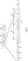
- FIG. 3 illustrates one example of such a frame structure that may be used in one or more standards of IEEE 802.11.
- the basic frame structure may include a preamble 300, header 301, and payload 301.
- the preamble 300 may include numerous sub-fields 310-314, as described subsequently, and may serve to alert a receiver (e.g., radio) of a wireless communication station 100, 102-104 that a transmission is about to start.
- the preamble 301 then enables the receiver to synchronize with the incoming transmission using a plurality of training sub-fields 314.
- the header 301 may immediately follow the preamble 300 in the frame.
- the header 301 may include information regarding the payload 302 to follow including the length of the data within the payload 302.
- the payload 302 may include the data that may be desired to be transferred to another wireless communication station 100, 102-104. In the IEEE 802.11 standards, the payload may range from 64 - 1500 bytes. Other examples of the present disclosure may have different size payloads.
- the payload 302 may be modulated using the same modulation scheme as the preamble 300 and header 301 or a different modulation scheme may be used.
- the preamble 300 may include numerous sub-fields 310-314.
- the preamble 300 may include numerous legacy fields 310-312 that may be used in older versions of a communication standard (e.g., 802.11a/g).
- legacy sub-fields 310-312 may enable communication with both wireless communication stations using new standards as well as wireless communication stations using the older standards.
- the legacy sub-fields 310-312 may include training fields such as a legacy short training field (L-STF) 310 and a legacy long training field (L-LTF) 311.
- the legacy sub-fields 310-312 may further include a legacy signal field (L-SIG) 312 that may be used to transfer a rate and length information of the frame.
- L-STF legacy short training field
- L-LTF legacy long training field
- L-SIG legacy signal field
- preamble sub-fields 310-314 may include a high throughput signal field (HT-SIG) 313 that may provide means to carry information used to interpret HT packet formats.
- HTTP-LTF high throughput long training fields
- HT-LTF high throughput long training fields
- the HT-LTF 314 subfields may comprise one or more portions.
- the first portion 320 may be referred to as data HT-LTF's and the second portion 321 may be referred to as extension HT-LTF's.
- the data HT-LTF sub-fields 320 may be used for demodulation of a high throughput data portion of the payload 302. This portion 320 may comprise one or more sub-fields and may be located immediately adjacent to the HT-SIG field 313.
- the extension HT-LTF sub-fields 321 may be used for probing extra spatial dimensions of the channel that may not be utilized by the HT-LTF data portion 320.
- This portion 321 may comprise one or more sub-fields and may be located immediately after the data HT-LTF data portion 320 and prior to the payload data.
- the initiating station may be either the mobile wireless station 100 or one of the access points 102-104.
- the responding station may be either the mobile wireless station 100 or one of the access points 102-104.
- the initiating station may be defined as the station that initiates the ToF request.
- the responding station may be defined as the station that responds to the ToF request.
- FIG. 4 illustrates a protocol flow diagram for ToF distance measurement for offloading ToF calculations to an initiating station in accordance with some examples of the present disclosure.
- the responding station instead of the responding station sending its ToF request frame received time and response frame transmit times to the initiating station, as is done in the prior art, unprocessed information on the responding station side may be transmitted to the initiating station side. The initiating station side may then derive these times. Thus, all of the ToF distance measurement calculations may then be performed on the initiating station side.
- the unprocessed information may include channel information as determined by the other side.
- channel information transmitted by the responding station may include the channel information of the channel from the initiating station to the responding station.
- the protocol flow diagram shows that the initiating station 400 begins by transmitting an action frame M1 to the responding station 401.
- the M1 frame is a request for ToF distance measurement.
- the TF_TOA is differentiated from the actual action frame time of arrival by the use of the "prime" indication.
- t 2 ′ is the training frame ToA whereas t 2 would be the actual ToA of M1 after correction from the channel information.
- t 2 ′ and t 4 ′ both refer to the time of arrival of the training frame used to calculate the channel information.
- the acknowledgement frame M1-ACK may be used for multiple functions.
- the M1-ACK may be used by the responding station 401 to inform the initiating station 400 that the ToF request was received.
- the training frame of M1-ACK may be used by the initiating station 400 to determine the channel information for the channel from the responding station 401 to the initiating station 400.
- the responding station 401 Since the responding station 401 may be offloading the ToF calculations to the initiating station 400, the responding station 401 now transmits an action frame M2 to the initiating station 400.
- the M2 frame may include the information packet that may be transmitted to the initiating station 400 for calculating the ToF distance information.
- the M2 frame may include the times t 2 ′ and t 3 and the channel information for the channel from the initiating station 400 to the responding station 401.
- the M2 frame may also include tokens, other time offsets, and frequency offsets.
- the M2 frame may be transmitted with the times received from (transmission not shown) the initiating station 400 such as t 4 ′ , t 1 and the channel information.
- the frame M2 may be transmitted as shown but an M3 frame may then be transmitted from the initiating station 400 to the responding station 401 with corresponding t 4 ′ , t 1 and the channel information.
- the M2 frame may also include a start time (e.g., location) of a particular symbol within the M1 frame.
- the symbol may be a modulated preamble field such as an HT-LTF or another preamble field.
- the symbol start time, t symStart may be defined as a location within the M1 frame in which the particular symbol starts. For example, the responding station 401 may know how far in to the frame the particular symbol starts. This symbol start time may then be transmitted to the initiating station 400 in the channel information field of M2.
- the M1 frame may be used for measurement and the M2 frame may be used to transfer the information packet to the initiating station 400 for calculating the ToF distance measurement.
- the above-described information received in the M2 frame may then be used by the initiating station 400 to determine an estimation of the channel information for the channel from the responding station 401 to the initiating station 400. This estimation of the channel information may then be used by the initiating station 400 in determining the ToA of the M2 frame at the initiating station 400.
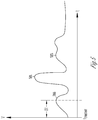
- FIG. 5 illustrates a typical time domain signal transmitted over a channel in the wireless communication system of FIG. 1 .
- This signal may be a multipath signal as received at the initiating station 400 that may result from the signal reflecting off different surfaces and arriving at the initiating station 400 at different times.
- the initial peak 500 may be the line of sight (LoS) received signal as received directly from the responding station 401 without any reflections.
- Another peak 501 may be a second path that, while stronger, arrives at a later time.
- Another peak 503 may be a third path that is received even later.
- the time ⁇ t may be defined as the time from t symStart until the first LoS peak is received.
- D may represent the sum of corrections from the two channel information or one correction from two channel information, depending on which offloading scheme may be used.
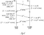
- FIG. 6 illustrates a protocol flow diagram for ToF distance measurements for offloading ToF calculations to a responding station 601 in accordance with some examples of the present disclosure.
- the ToF calculations may be performed on the responding station 601 side.
- the protocol flow diagram illustrates ToF distance measurement calculations being performed on a continuous basis over a period of time instead of the instantaneous measurement and calculation illustrated in FIG. 4 .
- the protocol flow diagram illustrates ToF distance measurement calculations being performed on a continuous basis over a period of time instead of the instantaneous measurement and calculation illustrated in FIG. 4 .
- neither the example of the present disclosure illustrated in FIG. 4 nor the example of the present disclosure illustrated in FIG. 6 are limited to either instantaneous or continuous calculations of the ToF distance measurement.
- the initiating station 600 may transmit action frame M k for ToF measurement requests to the responding station 601.
- the ToD M k t 1 k for the M k frame.
- the M k frame may comprise the previous times t 4 ′ k ⁇ 1 , t 1 k ⁇ 1 , and the channel information of the previous measurement (i.e., channel information (k-1) ) for the channel from the responding station 601 to the initiating station 600.
- the action frame M k may be used for the next measurement of ToF distance.
- the D (k-1) may be calculated at the responding station 601 from the channel information from both sides (i.e., initiating station to responding station and responding station to initiating station).
- the ToF k ⁇ 1 D k ⁇ 1 + t 4 ′ k ⁇ 1 ⁇ t 1 k ⁇ 1 ⁇ t 3 k ⁇ 1 ⁇ t 2 ′ k ⁇ 1 / 2 .
- the M k responses transmitted to the initiating station 600 may then include the requested ToF.
- the above protocol flow for the k-1 frame may continue with the k+1 frame.
- the initiating station 600 may transmit action frame M (k+1) for the ToF measurement request to the responding station 601.
- the ToD M k + 1 t 1 k + 1 for the M (k+1) frame.
- the M (k+1) frame may comprise the previous times t 4 ′ k , t 1 k , and the channel information of the previous measurement (i.e., channel information (k) ) for the channel from the responding station 601 to the initiating station 600.
- the offloading frame M (k+1) may be used for the next measurement of ToF distance.
- the D k may be calculated at the responding station 601 from the channel information from both sides (i.e., initiating station to responding station and responding station to initiating station).
- the ToF k D k + t 4 ′ k ⁇ t 1 k ⁇ t 3 k ⁇ t 2 ′ k / 2 .
- the M k+1 response transmitted to the initiating station 600 may then include the requested ToF.
- FIG. 7 illustrates a protocol flow diagram for ToF distance measurements for offloading ToF calculations to an initiating station using null data packet-like bi-directional channel estimation.
- the initiating station 700 transmits a frame that performs a ToF announce function. This frame announces to the responding station 701 that a subsequent frame will be a ToF request being made by the initiating station 700.
- SIFS short inter-frame space
- a SIFS interval may be defined as a time period of a particular size. The time period takes into account a time it takes for the arrival of the ToF-A frame to arrive at the antenna for the responding station 701 until a modem of the responding station 701 perceives it is receiving data. Additionally, SIFS also includes the time it takes the media access control (MAC) of the responding station 701 to process a frame and prepare a response. Finally, the SIFS also may include any time for the responding station 701 to transition from a receive mode to a transmit mode.
- MAC media access control
- Null data packets may be used for measuring the channel information and timing.
- the null data packet is a frame that does not include any payload (e.g., data). Such a frame may only include the preamble for receiver training purposes as well as a means for determining the channel information.
- Another SIFS time interval is used during which the responding station may be determining, using the NDP-1 frame preamble, the channel information for the channel between the initiating station 700 and the responding station 701.
- the responding station 701 transmits a ToF response frame (ToF-R) to the initiating station 700.
- the ToF-R frame includes the just determined channel information as well as ToA t 2 ′ and ToD t 3 .
- the ToD t 3 refers to the ToD of the subsequent NDP-2 frame transmitted by the responding station 701 to the initiating station 700 and may be calculated prior to the actual transmission.
- the initiating station 700 may use the preamble of the NDP-2 frame to determine the channel information for the channel between the responding station 701 and the initiating station 700.
- the initiating station 700 determines the ToF distance measurement using the channel information for the channel between the initiating station 700 and the responding station 701, that was transmitted by the responding station 701, and the channel information for the channel between the responding station 701 and the initiating station 700, that was determined by the initiating station 700.
- the NDP approach may allow greater flexibility with types of channels that can be measured (e.g., bandwidth, multiple inputs - multiple outputs, beam formed).
- the SIFS time interval may allow the modem on either side of the channel to prepare for the next frame.
- Examples of the present disclosure may be implemented in one or a combination of hardware, firmware and software. Examples of the present disclosure may also be implemented as instructions stored on a computer-readable storage device, which may be read and executed by at least one processor to perform the operations described herein.
- a computer-readable storage device may include any non-transitory mechanism for storing information in a form readable by a machine (e.g., a computer).
- a computer-readable storage device may include read-only memory (ROM), random-access memory (RAM), magnetic disk storage media, optical storage media, flash-memory devices, and other storage devices and media.
- a system may include one or more processors and may be configured with instructions stored on a computer-readable storage device.
Landscapes
- Engineering & Computer Science (AREA)
- Radar, Positioning & Navigation (AREA)
- Remote Sensing (AREA)
- Physics & Mathematics (AREA)
- General Physics & Mathematics (AREA)
- Computer Networks & Wireless Communication (AREA)
- Signal Processing (AREA)
- Mobile Radio Communication Systems (AREA)
- Radar Systems Or Details Thereof (AREA)
- Position Fixing By Use Of Radio Waves (AREA)
Description
- This application claims the benefit of priority to
U.S. Provisional Patent Application Serial No. 61/773,399, filed March 6, 2013 - Examples of the present disclosure pertain to wireless network communications. Some Examples of the present disclosure relate to the IEEE 802.11 standards. Some examples of the present disclosure relate to WiFi networks. Some examples of the present disclosure relate to beamforming. Some examples of the present disclosure relate to channel feedback, location positioning, and time-of-flight (ToF).
- Outdoor navigation is widely deployed through the use of various global-navigation-satellite-systems (GNSS) such as the U.S. Global Positioning System (GPS), the Russian Global Navigation Satellite System (GLONASS), and the European GALILEO. These systems may operate effectively outdoors but, due to satellite reception problems, may not be very effective indoors.
- Relatively recently, there has been a focus on solving indoor navigation problems. One solution may be based on Time-of-Flight (ToF) positioning methods. Time-of-Fight may be defined as the overall time a signal propagates from a mobile communication station (e.g., user) to an access point (AP) and back to the user. This value may then be converted into distance by dividing the time by two and multiplying the result by the speed of light. This method may be robust and scalable but may require hardware changes to the Wi-Fi modem.
- There are general needs for performing indoor navigation out of range of the GNSS.
US 2012/032855 A1 discloses high-resolution ranging and location finding using multicarrier signals. - The claims define the matter for protection.
-
-
FIG. 1 illustrates a block diagram of an example of a wireless communication system in accordance with some examples of the present disclosure. -
FIG. 2 illustrates a block diagram of an example of a wireless communication station in accordance with some examples of the present disclosure. -
FIG. 3 illustrates a diagram of an example of a frame structure in accordance with some examples of the present disclosure. -
FIG. 4 illustrates a protocol flow diagram for ToF distance measurement for offloading ToF calculations to an initiating station in accordance with some examples of the present disclosure. -
FIG. 5 illustrates a typical time domain signal transmitted over a channel in the wireless communication system ofFIG. 1 . -
FIG. 6 illustrates a protocol flow diagram for ToF distance measurements for offloading ToF calculations to a responding station in accordance with some examples of the present disclosure. -
FIG. 7 illustrates a protocol flow diagram for ToF distance measurements for offloading ToF calculations to an initiating station using null data packet-like bi-directional channel estimation in accordance with some examples of the present disclosure. -
Figure 4 and6 do not fall within the scope of the appended independent claims.Figures 1 to 3 and5 do not illustrate all the elements recited in the claims and/or also illustrate additional elements and/or show examples of how some elements of the claims could be implemented. - Subsequently described examples of the present disclosure refer to WiFi communication systems and Institute of Electrical and Electronics Engineers (IEEE) 802.11 (i.e., a set of physical layer standards for implementing wireless local area network (WLAN) computer communication). However, the present examples of the disclosure are not restricted to only a WiFi communication system or any particular communication standard. The present examples of the disclosure may be used in any communication system in which location and navigation capabilities may be desired.
- Time-of-Flight (ToF) positioning methods may provide a way to determine a mobile station's location in an environment where GNSS may not be available (e.g., indoors). Typical ToF methods may pose a barrier to entry since only those manufacturers having both navigation and WiFi technologies may implement this kind of solution.
- In present communication systems, two wireless communication stations may calculate a time-of-arrival (ToA) independently in order to perform a WiFi distance measurement. Each station may combine a Time of Arrival (ToA) of a frame with the Time of Departure (ToD) of the frame in order to determine a round trip time between the stations. Multiplying the round trip time by the speed of light and dividing by two may result in a distance from a station.
- The ToA calculation may be based on an analysis of channel information. The channel information refers to known channel properties of a communication link. The channel information may describe how a signal propagates from a transmitter to a receiver and may represent the combined effects of, for example, scattering, fading, and power decay with distance. The channel information may be described as a snapshot of the channel at a particular time, since the channel information may change as a mobile station moves about an area. Thus, new channel information may be used during each ToA calculation.
- The channel information for each channel may be determined by determining a distortion caused to a preamble of a frame transmitted over the channel. One example of such a preamble is illustrated in
FIG. 3 and described subsequently. Since the expected preamble may be known by the receiver as a standard preamble and the preamble as actually received may be now known, the receiver can determine the channel information by the distortion caused to the expected preamble. - Each station independently performing its own ToA analysis may introduce errors into the calculations due to only one side of the channel being taken into account. These errors may result in tens of meters of variation.
- A solution to this problem may be to have one station transfer its channel information to the other station. Thus the ToF calculation may be offloaded to only one station to improve the quality of the range estimation. More particularly, examples of the present disclosure provide a protocol to transfer the channel information from one side (e.g., a passive partner that only measures the channel information) to the other side (e.g., the "smart" partner) that may calculate the range estimation. Another advantage of this protocol may be the flexibility in choosing a type of offloading processing (e.g., from client to network, from network to client, or some combined method). The channel from the other side may be used to improve the quality of the range estimation by, for example: calculating a plurality of ToA hypotheses for each channel and select the best pair having the best likelihood of success, due to the physical channel nature where both channels are very similar, the two channels may be merged for an improved signal-to-noise ratio (SNR), or a combined estimation of range.
- The channel information may be transferred to the other side of the channel by any one of a plurality of different methods. For example, the entire, uncompressed channel information may be transferred, the channel information may be compressed, the channel information may be decimated in frequency, or a list of hypotheses (with or without weighting) for potential ToA timings may be transferred. The present examples of the disclosure are not limited to just these channel information transfer methods.
- In addition to improved accuracy and performance for ToF distance calculations, the present examples of the disclosure may allow a station (e.g., access point) that cannot handle multiple users with respect to inadequate processing power and/or memory for calculation of the ToA to offload most of the processing to other stations. Additionally, low power devices (e.g., mobile wireless stations) may offload the ToF distance calculations to a more powerful access point or its backbone.
-
FIG. 1 illustrates various network elements of a wireless communication network in accordance with some examples of the present disclosure. The wireless communication network includes one or morewireless communication stations 100, 102-104 that may include a mobilewireless station 100 and a plurality of access points (APs) 102-104 that may communicate over one or more wireless channels in accordance with IEEE 802.11 communication techniques. - The mobile
wireless station 100 may be a mobile communication device that is non-stationary. Such a communication device may include mobile radiotelephones, tablet computers, lap top computers, and other communication devices that may communicate with the access points 102-104 over one or more wireless channels using a communication technique (e.g., IEEE 802.11). - The access points 102-104 may have fixed locations. The access points 102-104 may be part of a stationary network that may be coupled to a larger network (e.g., local area network (LAN), wide area network (WAN)). For example, the access points 102-104 may be part of a wired network that is coupled to the Internet. The
mobile wireless station 100 may then access the larger network by communicating over the wireless channels with the access points 102-104. - It may be desirable for the
mobile wireless station 100 to know its location with relation to the access points 102-104. Since the geographical locations of the access points 102-104 may be fixed and known, the geographical location of themobile wireless station 100 may be determined by trilateration and tracked thereafter. The trilateration may be accomplished by using ToF calculations. In another example of the present disclosure, the access points 102-104 may be mobile and their location may be determined by GNSS or some other means. -
FIG. 2 is a functional block diagram of a wireless communication station in accordance with some examples of the present disclosure.Communication station 200 may be suitable for use as a mobile wireless communicator 100 (FIG. 1 ) or any of the access points 102-104 (FIG. 1 ), although other configurations may also be suitable. -
Communication station 200 may includephysical layer circuitry 202 to communicate wirelessly with access points, mobile communication devices, and other communication stations over one ormore antennas 205.Communication station 200 may also includeprocessing circuitry 204 coupled to thephysical layer circuitry 202 to perform other operations described herein. - In accordance with examples of the present disclosure, the
physical layer circuitry 202 may be configured to transmit and receive ToF messages between communication stations. Thephysical layer circuitry 202 may also be configured to transmit and receive acknowledgments as well as other communications between communication stations. Thephysical layer circuitry 202 may be configured to modulate digital data from theprocessing circuitry 204 for transmission over a channel as well as demodulate received modulated signals into digital data for use by theprocessing circuitry 204. - In accordance with examples of the present disclosure, the
processing circuitry 204 may be configured to calculate ToF measurements. Theprocessing circuitry 204 may also be configured to calculate time intervals such as ToA and ToD. - Although
communication station 200 is illustrated as having several separate functional elements, one or more of the functional elements may be combined and may be implemented by combinations of software-configured elements, such as processing elements including digital signal processors (DSPs), and/or other hardware elements. For example, some elements may comprise one or more microprocessors, DSPs, field-programmable gate arrays (FPGAs), application specific integrated circuits (ASICs), radio-frequency integrated circuits (RFICs) and combinations of various hardware and logic circuitry for performing at least the functions described herein. In some examples of the present disclosure, the functional elements ofcommunication station 200 may refer to one or more processes operating on one or more processing elements. - In some examples of the present disclosure,
communication station 200 may be part of a portable wireless communication device, such as a personal digital assistant (PDA), a laptop or portable computer with wireless communication capability, a web tablet, a wireless telephone, a smartphone, a wireless headset, a pager, an instant messaging device, a digital camera, an access point, a television, a medical device (e.g., a heart rate monitor, a blood pressure monitor, etc.), or other device that may receive and/or transmit information wirelessly. In some examples of the present disclosure, a communication station may include one or more of a keyboard, a display, a nonvolatile memory port, multiple antennas, a graphics processor, an application processor, speakers, and other mobile device elements. The display may be an LCD or LED screen, including a touch screen. - The
wireless communication stations 100, 102-104 in the network may communicate with each other over the one or more wireless channels using a frame structure. Some examples of the present disclosure may also refer to the frame as a packet.FIG. 3 illustrates one example of such a frame structure that may be used in one or more standards of IEEE 802.11. - The basic frame structure may include a
preamble 300,header 301, andpayload 301. Thepreamble 300 may include numerous sub-fields 310-314, as described subsequently, and may serve to alert a receiver (e.g., radio) of awireless communication station 100, 102-104 that a transmission is about to start. Thepreamble 301 then enables the receiver to synchronize with the incoming transmission using a plurality oftraining sub-fields 314. - The
header 301 may immediately follow thepreamble 300 in the frame. Theheader 301 may include information regarding thepayload 302 to follow including the length of the data within thepayload 302. - The
payload 302 may include the data that may be desired to be transferred to anotherwireless communication station 100, 102-104. In the IEEE 802.11 standards, the payload may range from 64 - 1500 bytes. Other examples of the present disclosure may have different size payloads. Thepayload 302 may be modulated using the same modulation scheme as thepreamble 300 andheader 301 or a different modulation scheme may be used. - The
preamble 300 may include numerous sub-fields 310-314. For example, thepreamble 300 may include numerous legacy fields 310-312 that may be used in older versions of a communication standard (e.g., 802.11a/g). Such legacy sub-fields 310-312 may enable communication with both wireless communication stations using new standards as well as wireless communication stations using the older standards. - The legacy sub-fields 310-312 may include training fields such as a legacy short training field (L-STF) 310 and a legacy long training field (L-LTF) 311. The legacy sub-fields 310-312 may further include a legacy signal field (L-SIG) 312 that may be used to transfer a rate and length information of the frame.
- Other preamble sub-fields 310-314 may include a high throughput signal field (HT-SIG) 313 that may provide means to carry information used to interpret HT packet formats. A plurality of high throughput long training fields (HT-LTF) 314 may provide means for the receiver to estimate the channel between each spatial mapping input and receiver.
- The HT-
LTF 314 subfields, in the present examples of the disclosure, may comprise one or more portions. Thefirst portion 320 may be referred to as data HT-LTF's and thesecond portion 321 may be referred to as extension HT-LTF's. - The data HT-
LTF sub-fields 320 may be used for demodulation of a high throughput data portion of thepayload 302. Thisportion 320 may comprise one or more sub-fields and may be located immediately adjacent to the HT-SIG field 313. - The extension HT-
LTF sub-fields 321 may be used for probing extra spatial dimensions of the channel that may not be utilized by the HT-LTF data portion 320. Thisportion 321 may comprise one or more sub-fields and may be located immediately after the data HT-LTF data portion 320 and prior to the payload data. - Subsequent discussion refers to "initiating station" and "responding station". The initiating station may be either the
mobile wireless station 100 or one of the access points 102-104. Similarly, the responding station may be either themobile wireless station 100 or one of the access points 102-104. The initiating station may be defined as the station that initiates the ToF request. The responding station may be defined as the station that responds to the ToF request. -
FIG. 4 illustrates a protocol flow diagram for ToF distance measurement for offloading ToF calculations to an initiating station in accordance with some examples of the present disclosure. In this example of the present disclosure, instead of the responding station sending its ToF request frame received time and response frame transmit times to the initiating station, as is done in the prior art, unprocessed information on the responding station side may be transmitted to the initiating station side. The initiating station side may then derive these times. Thus, all of the ToF distance measurement calculations may then be performed on the initiating station side. - The unprocessed information may include channel information as determined by the other side. In other words, channel information transmitted by the responding station may include the channel information of the channel from the initiating station to the responding station.
- The protocol flow diagram shows that the initiating
station 400 begins by transmitting an action frame M1 to the respondingstation 401. In an example of the present disclosure, the M1 frame is a request for ToF distance measurement. The M1 frame is shown being transmitted by the initiatingstation 400 at time of departure (ToD) = t 1. The M1 frame is received by the respondingstation 401 at a training frame time of arrival (TF_ToA) = t2 . - The TF_TOA is differentiated from the actual action frame time of arrival by the use of the "prime" indication. In other words,

- The responding
station 401 may transmit an acknowledgement frame M1-ACK to the initiatingstation 400 at ToD(M1-ACK) = t 3. The M1-ACK frame may be received at the initiatingstation 400 at


- The acknowledgement frame M1-ACK may be used for multiple functions. The M1-ACK may be used by the responding
station 401 to inform the initiatingstation 400 that the ToF request was received. The training frame of M1-ACK may be used by the initiatingstation 400 to determine the channel information for the channel from the respondingstation 401 to the initiatingstation 400. - Since the responding
station 401 may be offloading the ToF calculations to the initiatingstation 400, the respondingstation 401 now transmits an action frame M2 to the initiatingstation 400. The M2 frame may include the information packet that may be transmitted to the initiatingstation 400 for calculating the ToF distance information. The M2 frame may include thetimes 
station 400 to the respondingstation 401. The M2 frame may also include tokens, other time offsets, and frequency offsets. In another example of the present disclosure, the M2 frame may be transmitted with the times received from (transmission not shown) the initiatingstation 400 such as
station 400 to the respondingstation 401 withcorresponding 
- The M2 frame may also include a start time (e.g., location) of a particular symbol within the M1 frame. The symbol may be a modulated preamble field such as an HT-LTF or another preamble field. The symbol start time, tsymStart, may be defined as a location within the M1 frame in which the particular symbol starts. For example, the responding
station 401 may know how far in to the frame the particular symbol starts. This symbol start time may then be transmitted to the initiatingstation 400 in the channel information field of M2. - Thus, the M1 frame may be used for measurement and the M2 frame may be used to transfer the information packet to the initiating
station 400 for calculating the ToF distance measurement. The above-described information received in the M2 frame may then be used by the initiatingstation 400 to determine an estimation of the channel information for the channel from the respondingstation 401 to the initiatingstation 400. This estimation of the channel information may then be used by the initiatingstation 400 in determining the ToA of the M2 frame at the initiatingstation 400. - The ToA of the M2 frame at the initiating
station 400 may be determined by tToA = tsymbStart + Δt - tHW-delay, where tsymbStart is the start time of the symbol as previously described, Δt is a time difference between tsymbStart and the first line of sight peak as described subsequently, and tHW-delay is an inherent hardware delay imposed by the respondingstation 401 during transmission of M2. -
FIG. 5 illustrates a typical time domain signal transmitted over a channel in the wireless communication system ofFIG. 1 . This signal may be a multipath signal as received at the initiatingstation 400 that may result from the signal reflecting off different surfaces and arriving at the initiatingstation 400 at different times. Theinitial peak 500 may be the line of sight (LoS) received signal as received directly from the respondingstation 401 without any reflections. Anotherpeak 501 may be a second path that, while stronger, arrives at a later time. Anotherpeak 503 may be a third path that is received even later. The time Δt may be defined as the time from tsymStart until the first LoS peak is received. - Once the initiating
station 400 has determined the ToA as discussed previously, the initiatingstation 400 may now determine the ToF distance measurement. This may be accomplished by
-
FIG. 6 illustrates a protocol flow diagram for ToF distance measurements for offloading ToF calculations to a respondingstation 601 in accordance with some examples of the present disclosure. In this example of the present disclosure, the ToF calculations may be performed on the respondingstation 601 side. - The protocol flow diagram illustrates ToF distance measurement calculations being performed on a continuous basis over a period of time instead of the instantaneous measurement and calculation illustrated in
FIG. 4 . However, neither the example of the present disclosure illustrated inFIG. 4 nor the example of the present disclosure illustrated inFIG. 6 are limited to either instantaneous or continuous calculations of the ToF distance measurement. - Referring to
FIG. 6 , the initiatingstation 600 may transmit action frame Mk for ToF measurement requests to the respondingstation 601. The
previous times 

station 601 to the initiatingstation 600. In another example of the present disclosure, the action frame Mk may be used for the next measurement of ToF distance. - The responding
station 601 receives the training frame of the Mk frame at
station 601 may then transmit a Mk response frame at times
station 601 from the channel information from both sides (i.e., initiating station to responding station and responding station to initiating station). Thus the
station 600 may then include the requested ToF. The respondingstation 600 may receive the training frame of the Mk response frame at
- As seen in
FIG. 6 , the above protocol flow for the k-1 frame may continue with the k+1 frame. Thus, the initiatingstation 600 may transmit action frame M(k+1) for the ToF measurement request to the respondingstation 601. The
previous times 

station 601 to the initiatingstation 600. In another example of the present disclosure, the offloading frame M(k+1) may be used for the next measurement of ToF distance. - The responding
station 601 receives the training frame of the M(k+1) frame at
station 601 may then transmit the Mk response frame at
station 601 from the channel information from both sides (i.e., initiating station to responding station and responding station to initiating station). Thus the
station 600 may then include the requested ToF. The respondingstation 600 may receive the training frame of the Mk+1 response frame at
-
FIG. 7 illustrates a protocol flow diagram for ToF distance measurements for offloading ToF calculations to an initiating station using null data packet-like bi-directional channel estimation. The initiatingstation 700 transmits a frame that performs a ToF announce function. This frame announces to the respondingstation 701 that a subsequent frame will be a ToF request being made by the initiatingstation 700. A short inter-frame space (SIFS) time interval then occurs between the ToF-A frame and the initiatingstation 700 transmitting a null data packet frame (NDP-1) to the respondingstation 701 at ToD(NDP-1) = t 1 . - A SIFS interval may be defined as a time period of a particular size. The time period takes into account a time it takes for the arrival of the ToF-A frame to arrive at the antenna for the responding
station 701 until a modem of the respondingstation 701 perceives it is receiving data. Additionally, SIFS also includes the time it takes the media access control (MAC) of the respondingstation 701 to process a frame and prepare a response. Finally, the SIFS also may include any time for the respondingstation 701 to transition from a receive mode to a transmit mode. - Null data packets may be used for measuring the channel information and timing. As the name implies, the null data packet is a frame that does not include any payload (e.g., data). Such a frame may only include the preamble for receiver training purposes as well as a means for determining the channel information.
- The responding
station 701 receives the training frame of the NDP-1 frame at
station 700 and the respondingstation 701. - The responding
station 701, after the SIFS time interval, then transmits a ToF response frame (ToF-R) to the initiatingstation 700. The ToF-R frame includes the just determined channel information as well asToA 
station 701 to the initiatingstation 700 and may be calculated prior to the actual transmission. The initiatingstation 700 then receives the training frame of the NDP-2 frame at
station 700 may use the preamble of the NDP-2 frame to determine the channel information for the channel between the respondingstation 701 and the initiatingstation 700. - The initiating
station 700 then determines the ToF distance measurement using the channel information for the channel between the initiatingstation 700 and the respondingstation 701, that was transmitted by the respondingstation 701, and the channel information for the channel between the respondingstation 701 and the initiatingstation 700, that was determined by the initiatingstation 700. The initiatingstation 701 may use the calculation ToF =
- Examples of the present disclosure may be implemented in one or a combination of hardware, firmware and software. Examples of the present disclosure may also be implemented as instructions stored on a computer-readable storage device, which may be read and executed by at least one processor to perform the operations described herein. A computer-readable storage device may include any non-transitory mechanism for storing information in a form readable by a machine (e.g., a computer). For example, a computer-readable storage device may include read-only memory (ROM), random-access memory (RAM), magnetic disk storage media, optical storage media, flash-memory devices, and other storage devices and media. In some examples of the present disclosure, a system may include one or more processors and may be configured with instructions stored on a computer-readable storage device.
Claims (5)
- An apparatus for inclusion in a station, STA, (700) configured to operate in a wireless local area network, WLAN, the apparatus, when included in the STA, to cause the STA to perform, as an initiator, a time-of-flight, ToF measurement protocol with a responder (701), the apparatus comprising:processing circuitry to generate an announcement packet and a first null-data packet, NDP, for transmission to the responder as a first sequence;processing circuitry to initiate transmission by the STA (700) of the first sequence such that the first NDP follows the announcement packet by a short inter-frame space, SIFS;processing circuitry to initiate reception by the STA (700) of a second sequence transmitted by the responder after a SIFS following reception of the first sequence by the responder, the second sequence comprising a second NDP and a measurement response, wherein the measurement response includes channel information determined by the responder using the first NDP, a time of arrival of the first NDP and a time of departure of the second NDP; andprocessing circuitry to cause the STA (700) to perform, as the initiator, a ToF computation to determine a distance to the responder, the ToF computation based on the measurement response and on channel information determined by the STA, as the initiator, using the second NDP.
- An apparatus for inclusion in a station, STA, (701) configured to operate in a wireless local area network, WLAN, the apparatus, when included in the STA, to cause the STA to perform, as a responder, a time-of-flight, ToF, measurement protocol with an initiator (700), the apparatus comprising:processing circuitry to initiate reception, by the STA, of an announcement packet and a first null-data packet, NDP, from the initiator as a first sequence, wherein the first NDP follows the announcement packet by a short inter-frame space, SIFS;processing circuitry to generate a second sequence comprising a second NDP and a measurement response, wherein the measurement response includes channel information determined by the STA using the first NDP, a time of arrival of the first NDP and a time of departure of the second NDP;processing circuitry to cause the STA to initiate transmission by the STA of the second sequence transmitted by the STA after a SIFS following reception of the first sequence by the STA; andwherein in the ToF measurement protocol a ToF computation to determine a distance to the initiator is offloaded to the initiator.
- A method for operating a station, STA, (700) in a wireless local area network, WLAN, the method to cause the STA (700) to perform, as an initiator, a time-of-flight, ToF, measurement protocol with a responder (701), the method comprising:generating an announcement packet and a first a null-data packet, NDP, for transmission to the responder as a first sequence;initiating transmission of the first sequence such that the first NDP follows the announcement packet by a short inter-frame space, SIFS;initiating reception of a second sequence transmitted by the responder after a SIFS following reception of the first sequence by the responder, the second sequence comprising a second NDP and a measurement response, wherein the measurement response includes channel information determined by the responder using the first NDP, a time of arrival of the first NDP and a time of departure of the second NDP; andperforming, as the initiator, a ToF computation to determine a distance to the responder, the ToF computation based on the measurement response and on channel information determined by the STA, as the initiator, using the second NDP.
- A method for operating a station, STA, (701) in a wireless local area network, WLAN, the method to cause the STA (701) to perform, as a responder, a time-of-flight, ToF, measurement protocol with an initiator (700), the method comprising:initiating reception of an announcement packet and a first null-data packet, NDP, from the initiator as a first sequence, wherein the first NDP follows the announcement packet by a short inter-frame space, SIFS;generating a second sequence comprising a second NDP and a measurement response, wherein the measurement response includes channel information determined by the STA using the first NDP, a time of arrival of the first NDP and a time of departure of the second NDP;initiating transmission of the second sequence transmitted by the STA after a SIFS following reception of the first sequence by the STA; andoffloading to the initiator a ToF computation to determine a distance to the initiator.
- At least one computer-readable storage medium comprising instructions that, when executed by processing circuitry of a station, STA, configured for operation in a wireless local area network, WLAN, cause the STA to execute the method according to any one of claims 3-4.
Applications Claiming Priority (2)
| Application Number | Priority Date | Filing Date | Title |
|---|---|---|---|
| US201361773399P | 2013-03-06 | 2013-03-06 | |
| PCT/US2013/060420 WO2014137391A1 (en) | 2013-03-06 | 2013-09-18 | System and method for channel information exchange for time of flight range determination |
Publications (3)
| Publication Number | Publication Date |
|---|---|
| EP2965111A1 EP2965111A1 (en) | 2016-01-13 |
| EP2965111A4 EP2965111A4 (en) | 2016-11-02 |
| EP2965111B1 true EP2965111B1 (en) | 2021-05-19 |
Family
ID=51491741
Family Applications (1)
| Application Number | Title | Priority Date | Filing Date |
|---|---|---|---|
| EP13877106.8A Active EP2965111B1 (en) | 2013-03-06 | 2013-09-18 | System and method for channel information exchange for time of flight range determination |
Country Status (7)
| Country | Link |
|---|---|
| US (2) | US9261580B2 (en) |
| EP (1) | EP2965111B1 (en) |
| JP (2) | JP6300834B2 (en) |
| KR (2) | KR101826213B1 (en) |
| CN (2) | CN110087178B (en) |
| TW (1) | TWI522640B (en) |
| WO (1) | WO2014137391A1 (en) |
Families Citing this family (55)
| Publication number | Priority date | Publication date | Assignee | Title |
|---|---|---|---|---|
| US9125168B2 (en) | 2013-01-23 | 2015-09-01 | Intel Corporation | Polled time-of-flight response |
| EP2959309B1 (en) * | 2013-02-19 | 2019-05-15 | Intel IP Corporation | Improved wireless network location techniques |
| KR101826213B1 (en) * | 2013-03-06 | 2018-02-06 | 인텔 코포레이션 | System and method for channel information exchange for time of flight range determination |
| KR101836014B1 (en) * | 2013-09-18 | 2018-03-07 | 인텔 코포레이션 | Fine-timing measurement for time-of-flight positioning |
| WO2015088496A1 (en) * | 2013-12-10 | 2015-06-18 | Intel IP Corporation | Techniques for wireless time-of-flight calculation complexity reduction |
| US9753129B2 (en) * | 2014-02-03 | 2017-09-05 | Google Inc. | Mapping positions of devices using audio |
| US9907044B2 (en) * | 2014-09-15 | 2018-02-27 | Qualcomm Incorporated | IEEE 802.11 enhancements for high efficiency positioning |
| US9651655B2 (en) * | 2015-01-03 | 2017-05-16 | Autotalks Ltd. | Positioning enhancement through time-of-flight measurement in WLAN |
| US9846220B2 (en) | 2015-08-19 | 2017-12-19 | Locix, Inc. | Systems and methods for determining locations of wireless sensor nodes in a network architecture having mesh-based features for localization |
| US10200964B2 (en) * | 2015-11-02 | 2019-02-05 | Intel IP Corporation | Apparatus, system and method of fine timing measurement (FTM) |
| US10172025B2 (en) * | 2015-11-13 | 2019-01-01 | Qualcomm Incorporated | Methods and systems for a ranging protocol |
| US10341979B2 (en) * | 2015-11-20 | 2019-07-02 | Qualcomm Incorporated | Secure fine timing measurement protocol |
| JP6437909B2 (en) * | 2015-12-18 | 2018-12-12 | 大井電気株式会社 | Base station and radio communication system |
| US20170261591A1 (en) * | 2016-03-14 | 2017-09-14 | Qualcomm Incorporated | Packet extensions for ranging operations |
| CN107205265B (en) * | 2016-03-16 | 2020-02-14 | 华为技术有限公司 | Wireless fidelity WI-FI ranging method, related equipment and system |
| US10470156B2 (en) * | 2016-06-03 | 2019-11-05 | Locix, Inc. | Systems and methods for coarse and fine time of flight estimates for precise radio frequency localization in the presence of multiple communication paths |
| US10757675B2 (en) * | 2016-06-03 | 2020-08-25 | Locix, Inc. | Systems and methods for precise radio frequency localization in the presence of multiple communication paths |
| US10278151B2 (en) * | 2016-06-15 | 2019-04-30 | Qualcomm Incorporated | Combined fine timing measurement (FTM) and non-FTM messaging for estimating turn-around calibration factor |
| US10455350B2 (en) | 2016-07-10 | 2019-10-22 | ZaiNar, Inc. | Method and system for radiolocation asset tracking via a mesh network |
| JP6802356B2 (en) * | 2016-08-01 | 2020-12-16 | テレフオンアクチーボラゲット エルエム エリクソン(パブル) | Communication nodes and methods for positioning in wireless communication networks |
| WO2018095555A1 (en) * | 2016-11-28 | 2018-05-31 | Telefonaktiebolaget Lm Ericsson (Publ) | Ta dependent harq feedback/ul grant timing determination |
| CN109891958B (en) * | 2016-11-28 | 2021-10-29 | 英特尔公司 | Apparatus, system and method for ranging measurement |
| WO2018150474A1 (en) * | 2017-02-14 | 2018-08-23 | Quadrac株式会社 | Device and system |
| WO2018187725A1 (en) * | 2017-04-07 | 2018-10-11 | Marvell World Trade Ltd. | Ranging measurements in wireless communication systems |
| EP3615954B1 (en) | 2017-04-25 | 2025-06-04 | Marvell Semiconductor, Inc. | Null data packet (ndp) ranging measurement feedback |
| WO2018231727A1 (en) * | 2017-06-12 | 2018-12-20 | Intel Corporation | Enhanced location measurements for wireless communication |
| CN107450049A (en) * | 2017-07-10 | 2017-12-08 | 武汉米风通信技术有限公司 | Reach the accurate calculation method of Positioning System time difference |
| US10568064B2 (en) | 2017-08-23 | 2020-02-18 | Locix, Inc. | Systems and methods for precise radio frequency localization using time difference of arrival |
| US10605889B2 (en) | 2017-08-23 | 2020-03-31 | Locix, Inc. | Systems and methods for precise radio frequency localization using time sweep time difference of arrival |
| US10838037B2 (en) | 2017-08-23 | 2020-11-17 | Locix, Inc. | Systems and methods for precise radio frequency localization using non-contiguous or discontinuous channels |
| EP3451756B1 (en) * | 2017-08-31 | 2022-04-06 | MediaTek Singapore Pte. Ltd. | Timing measurement techniques for determining distance in wireless networks |
| CN111052819A (en) * | 2017-09-06 | 2020-04-21 | 洛希克斯有限公司 | System and method for coarse and fine time-of-flight estimation for fine radio frequency positioning in presence of multiple communication paths |
| WO2019051036A1 (en) * | 2017-09-10 | 2019-03-14 | Intel IP Corporation | Apparatus, system and method of collaborative time of arrival (ctoa) measurement |
| JP7000576B2 (en) * | 2017-12-21 | 2022-01-19 | オカド・イノベーション・リミテッド | Positioning devices, communication systems and methods |
| JP6850739B2 (en) * | 2018-01-17 | 2021-03-31 | 日本電信電話株式会社 | Radio terminal station position estimation method and wireless base station |
| JP2019128222A (en) * | 2018-01-24 | 2019-08-01 | 沖電気工業株式会社 | Wireless device, wireless system and program |
| WO2019147319A1 (en) * | 2018-01-29 | 2019-08-01 | Marvell World Trade Ltd. | Error recovery in null data packet (ndp) ranging |
| CN110221243B (en) * | 2018-03-02 | 2022-06-17 | 阿里巴巴集团控股有限公司 | Positioning method and system of communication network |
| US11032787B2 (en) * | 2018-04-02 | 2021-06-08 | Nxp Usa, Inc. | Basic service set (BSS) color in null data packet (NDP) ranging |
| US10802104B2 (en) | 2018-12-26 | 2020-10-13 | Locix, Inc. | Systems and methods for using ranging and triangulation to determine locations of wireless sensor nodes based on radio frequency communications between the nodes and various RF-enabled devices |
| JP7273540B2 (en) * | 2019-02-28 | 2023-05-15 | キヤノン株式会社 | Communication device and its communication method, information processing device and its control method, and program |
| CN109819399A (en) * | 2019-03-15 | 2019-05-28 | 江苏中利电子信息科技有限公司 | The transmission method of network node location information based on 802.11 beacon frames |
| US11057850B1 (en) * | 2019-06-10 | 2021-07-06 | Marvell Asia Pte, Ltd. | Transmit power control for null data packets |
| CN112135316B (en) * | 2019-06-24 | 2024-04-12 | 华为技术有限公司 | Positioning method and device |
| KR102189831B1 (en) * | 2019-07-04 | 2020-12-11 | 동아대학교 산학협력단 | Synchronization method among multiple microwave wireless power transmission nodes for improving wireless power transmission efficiency based on distributed collaboration and wireless power transmission system using the same |
| US11265842B2 (en) | 2020-03-09 | 2022-03-01 | Cisco Technology, Inc. | Wireless station ranging using channel state |
| WO2021251541A1 (en) * | 2020-06-11 | 2021-12-16 | 엘지전자 주식회사 | Method and device for performing wi-fi sensing in wireless lan system |
| US11991586B2 (en) * | 2020-09-04 | 2024-05-21 | Apple Inc. | Techniques for changing frequency of ranging based on location of mobile device |
| US20240064804A1 (en) * | 2020-12-23 | 2024-02-22 | Lg Electronics Inc. | Improved wireless lan sensing procedure |
| CN117397309A (en) | 2021-06-01 | 2024-01-12 | 三星电子株式会社 | Electronic device for receiving arrival time difference messages and operating method of the electronic device |
| EP4318039A4 (en) | 2021-06-01 | 2024-09-25 | Samsung Electronics Co., Ltd. | ELECTRONIC DEVICE AND METHOD FOR CARRYING OUT A DISTANCE MEASUREMENT PROCESS |
| WO2023003388A1 (en) * | 2021-07-21 | 2023-01-26 | 엘지전자 주식회사 | Method and device for performing sensing procedure in wireless lan system |
| US12245182B2 (en) * | 2022-11-04 | 2025-03-04 | Silicon Laboratories Inc. | Improving accuracy of round-trip time (RTT) in high accuracy distance measurements (HADM) |
| CN115792937B (en) * | 2022-12-20 | 2026-02-10 | 浩云科技股份有限公司 | A TOF ranging method and device |
| US12181564B1 (en) * | 2023-12-20 | 2024-12-31 | Sr Technologies, Inc. | Dual round trip time mitigation for wireless local area network devices |
Family Cites Families (41)
| Publication number | Priority date | Publication date | Assignee | Title |
|---|---|---|---|---|
| JP3299927B2 (en) * | 1998-01-29 | 2002-07-08 | 沖電気工業株式会社 | Mobile communication system and mobile station position estimation method |
| US6133876A (en) * | 1998-03-23 | 2000-10-17 | Time Domain Corporation | System and method for position determination by impulse radio |
| KR100689566B1 (en) * | 2003-03-08 | 2007-03-02 | 삼성전자주식회사 | Handoff System and Method using Initial Ranging in Broadband Wireless Access Communication System |
| US7203500B2 (en) * | 2003-08-01 | 2007-04-10 | Intel Corporation | Apparatus and associated methods for precision ranging measurements in a wireless communication environment |
| US20050058081A1 (en) | 2003-09-16 | 2005-03-17 | Elliott Brig Barnum | Systems and methods for measuring the distance between devices |
| US7324824B2 (en) * | 2003-12-09 | 2008-01-29 | Awarepoint Corporation | Wireless network monitoring system |
| US7209071B1 (en) * | 2004-05-07 | 2007-04-24 | Steele Boring | System and method for distance measurement |
| US7057178B1 (en) | 2004-11-15 | 2006-06-06 | General Electric Company | Method and system for imaging using a filter for Time-of-Flight PET |
| JP4561329B2 (en) * | 2004-11-18 | 2010-10-13 | ソニー株式会社 | Ranging system, transmitting terminal, receiving terminal, ranging method, and computer program |
| FR2880499A1 (en) * | 2005-01-03 | 2006-07-07 | France Telecom | OPERATING A RADIOCOMMUNICATION FRAME WITHIN A SYSTEM OF AT LEAST THREE RADIO TRANSCEIVER-RECEIVER EQUIPMENT |
| FR2880508A1 (en) | 2005-01-03 | 2006-07-07 | France Telecom | METHOD FOR MEASURING A DISTANCE BETWEEN TWO RADIOCOMMUNICATION EQUIPMENTS, AND EQUIPMENT ADAPTED TO IMPLEMENT SUCH A METHOD |
| US7877101B1 (en) | 2006-12-28 | 2011-01-25 | Marvell International Ltd. | Locating a WLAN station using signal propagation delay |
| CA2744847C (en) * | 2005-11-07 | 2013-09-10 | Qualcomm Incorporated | Positioning for wlans and other wireless networks |
| US8711038B2 (en) * | 2006-10-05 | 2014-04-29 | Her Majesty The Queen In Right Of Canada As Represented By The Minister Of Industry, Through The Communications Research Centre Canada | High-resolution ranging and location finding using multicarrier signals |
| FR2908260A1 (en) | 2006-11-07 | 2008-05-09 | France Telecom | Initiating and requesting radio equipments' i.e. sensor, distance estimating method for e.g. ultra wideband radio system, involves sending frame and estimating flight time difference by respective equipments, and determining flight time |
| US7463194B1 (en) * | 2007-05-16 | 2008-12-09 | Mitsubishi Electric Research Laboratories, Inc. | Method for reducing radio ranging errors due to clock frequency offsets |
| KR101481592B1 (en) * | 2008-04-04 | 2015-01-12 | 엘지전자 주식회사 | Transmitting method of signals using the relay station in wireless communication system |
| US20100135178A1 (en) | 2008-11-21 | 2010-06-03 | Qualcomm Incorporated | Wireless position determination using adjusted round trip time measurements |
| US8582539B2 (en) | 2008-11-24 | 2013-11-12 | Qualcomm Incorporated | System and method to implement synchronous channel timing in a wireless communications network |
| KR101182861B1 (en) * | 2008-12-22 | 2012-09-14 | 한국전자통신연구원 | Distance measuring method |
| JP5163507B2 (en) * | 2009-01-14 | 2013-03-13 | 富士通株式会社 | Receiver, communication system and communication method |
| US8126405B2 (en) * | 2009-02-10 | 2012-02-28 | Mitsubishi Electric Research Laboratory, Inc. | Method for estimating condition of wireless channels |
| JP5285497B2 (en) * | 2009-03-12 | 2013-09-11 | 株式会社エヌ・ティ・ティ・ドコモ | Mobile communication method and radio base station |
| JP5546041B2 (en) * | 2009-04-27 | 2014-07-09 | シャープ株式会社 | Interference suppression radio communication system and interference suppression radio communication apparatus |
| US20100329236A1 (en) * | 2009-06-26 | 2010-12-30 | Qualcomm Incorporated | Method and apparatus for multiple user uplink requiring minimal station timing and frequency synchronization |
| US9392621B2 (en) * | 2009-06-26 | 2016-07-12 | Qualcomm Incorporated | Initiating a random access procedure for determining communication parameters |
| US8391382B2 (en) * | 2009-07-14 | 2013-03-05 | Lg Electronics Inc. | Method and apparatus for generating ranging preamble code in wireless communication system |
| US8233457B1 (en) * | 2009-09-03 | 2012-07-31 | Qualcomm Atheros, Inc. | Synchronization-free station locator in wireless network |
| US8948063B2 (en) | 2010-01-14 | 2015-02-03 | Qualcomm Incorporated | Method and system for real-time calibration and reporting of processing delay |
| US20110199946A1 (en) * | 2010-02-17 | 2011-08-18 | Qualcomm Incorporated | Method and apparatus for supporting adaptive channel state information feedback rate in multi-user communication systems |
| KR101711930B1 (en) * | 2010-07-05 | 2017-03-06 | 삼성전자주식회사 | System and method for terminal identifier switching in wireless communication system |
| US9606219B2 (en) * | 2010-08-02 | 2017-03-28 | Progeny Systems Corporation | Systems and methods for locating a target in a GPS-denied environment |
| US9166681B2 (en) * | 2010-10-13 | 2015-10-20 | Telefonaktiebolaget L M Ericsson (Publ) | Determining asymmetries in a communication network |
| WO2012054694A1 (en) * | 2010-10-21 | 2012-04-26 | Mediatek Singapore Pte. Ltd. | Integrity and quality monitoring and signaling for sounding and reduced feedback |
| US20120163261A1 (en) * | 2010-12-23 | 2012-06-28 | Texas Instruments Incorporated | Timing measurements between wireless stations with reduced power consumption |
| US9059821B2 (en) * | 2011-08-02 | 2015-06-16 | Celeno Communications (Israel) Ltd. | Carrier grouping schemes for wireless local area networks |
| CN103188791B (en) * | 2011-12-28 | 2016-07-13 | 华为终端有限公司 | A kind of localization method, client and alignment system |
| CN103959844A (en) * | 2012-03-19 | 2014-07-30 | 瑞典爱立信有限公司 | Null-data packet throughput system and method |
| JP2014019778A (en) | 2012-07-18 | 2014-02-03 | Nitto Denko Corp | Surface protection sheet |
| US20140073352A1 (en) * | 2012-09-11 | 2014-03-13 | Qualcomm Incorporated | Method for precise location determination |
| KR101826213B1 (en) | 2013-03-06 | 2018-02-06 | 인텔 코포레이션 | System and method for channel information exchange for time of flight range determination |
-
2013
- 2013-09-18 KR KR1020157021165A patent/KR101826213B1/en active Active
- 2013-09-18 CN CN201910023126.3A patent/CN110087178B/en active Active
- 2013-09-18 CN CN201380072206.9A patent/CN104981711A/en active Pending
- 2013-09-18 WO PCT/US2013/060420 patent/WO2014137391A1/en not_active Ceased
- 2013-09-18 US US14/127,385 patent/US9261580B2/en not_active Expired - Fee Related
- 2013-09-18 EP EP13877106.8A patent/EP2965111B1/en active Active
- 2013-09-18 KR KR1020187003089A patent/KR102004104B1/en active Active
- 2013-09-18 JP JP2015557996A patent/JP6300834B2/en active Active
-
2014
- 2014-03-05 TW TW103107484A patent/TWI522640B/en active
-
2016
- 2016-02-04 US US15/015,308 patent/US10064154B2/en active Active
-
2018
- 2018-02-27 JP JP2018032755A patent/JP6496854B2/en active Active
Non-Patent Citations (1)
| Title |
|---|
| None * |
Also Published As
| Publication number | Publication date |
|---|---|
| KR20180026737A (en) | 2018-03-13 |
| CN110087178A (en) | 2019-08-02 |
| KR102004104B1 (en) | 2019-07-25 |
| CN110087178B (en) | 2021-06-29 |
| US20150168536A1 (en) | 2015-06-18 |
| US20170013584A1 (en) | 2017-01-12 |
| JP2018102001A (en) | 2018-06-28 |
| TW201447345A (en) | 2014-12-16 |
| US10064154B2 (en) | 2018-08-28 |
| EP2965111A4 (en) | 2016-11-02 |
| TWI522640B (en) | 2016-02-21 |
| JP6300834B2 (en) | 2018-03-28 |
| JP6496854B2 (en) | 2019-04-10 |
| KR20150104162A (en) | 2015-09-14 |
| EP2965111A1 (en) | 2016-01-13 |
| KR101826213B1 (en) | 2018-02-06 |
| WO2014137391A1 (en) | 2014-09-12 |
| JP2016514250A (en) | 2016-05-19 |
| CN104981711A (en) | 2015-10-14 |
| US9261580B2 (en) | 2016-02-16 |
Similar Documents
| Publication | Publication Date | Title |
|---|---|---|
| EP2965111B1 (en) | System and method for channel information exchange for time of flight range determination | |
| EP2984501B1 (en) | System and method for channel feedback for location time of flight | |
| US12382251B2 (en) | User equipment positioning in long-term evolution coordinated multipoint communication systems | |
| US20240430845A1 (en) | Method and device for user equipment positioning | |
| US12057918B2 (en) | Non-line-of-sight path detection for user equipment positioning in wireless networks | |
| EP3420742B1 (en) | Unicast and broadcast protocol for wireless local area network ranging and direction finding | |
| US11131743B2 (en) | Unicast and broadcast protocol for wireless local area network ranging and direction finding | |
| RU2632475C1 (en) | Positioning on time of distribution initiated by access point | |
| US20170367063A1 (en) | Combined fine timing measurement (ftm) and non-ftm messaging for estimating turn-around calibration factor | |
| US20250126506A1 (en) | Sensing operation using a differential measurement based on a different propagation paths | |
| EP4027162A1 (en) | Positioning method, device, system, chip, and storage medium | |
| WO2023033836A1 (en) | Apparatus and method of performing an anti-multipath function to calibrate an antenna array | |
| WO2023033835A1 (en) | Apparatus and method of beam parameter estimation for line-of-sight determination | |
| WO2024075098A1 (en) | Repeater signal pattern as assisting information |
Legal Events
| Date | Code | Title | Description |
|---|---|---|---|
| PUAI | Public reference made under article 153(3) epc to a published international application that has entered the european phase |
Free format text: ORIGINAL CODE: 0009012 |
|
| 17P | Request for examination filed |
Effective date: 20150803 |
|
| AK | Designated contracting states |
Kind code of ref document: A1 Designated state(s): AL AT BE BG CH CY CZ DE DK EE ES FI FR GB GR HR HU IE IS IT LI LT LU LV MC MK MT NL NO PL PT RO RS SE SI SK SM TR |
|
| AX | Request for extension of the european patent |
Extension state: BA ME |
|
| DAX | Request for extension of the european patent (deleted) | ||
| A4 | Supplementary search report drawn up and despatched |
Effective date: 20161005 |
|
| RIC1 | Information provided on ipc code assigned before grant |
Ipc: G01S 13/87 20060101ALI20160928BHEP Ipc: H04W 84/12 20090101ALN20160928BHEP Ipc: G01S 5/14 20060101AFI20160928BHEP |
|
| STAA | Information on the status of an ep patent application or granted ep patent |
Free format text: STATUS: EXAMINATION IS IN PROGRESS |
|
| 17Q | First examination report despatched |
Effective date: 20180323 |
|
| GRAP | Despatch of communication of intention to grant a patent |
Free format text: ORIGINAL CODE: EPIDOSNIGR1 |
|
| STAA | Information on the status of an ep patent application or granted ep patent |
Free format text: STATUS: GRANT OF PATENT IS INTENDED |
|
| RIC1 | Information provided on ipc code assigned before grant |
Ipc: G01S 5/14 20060101AFI20190920BHEP Ipc: H04W 84/12 20090101ALN20190920BHEP Ipc: G01S 13/87 20060101ALI20190920BHEP |
|
| INTG | Intention to grant announced |
Effective date: 20191029 |
|
| GRAJ | Information related to disapproval of communication of intention to grant by the applicant or resumption of examination proceedings by the epo deleted |
Free format text: ORIGINAL CODE: EPIDOSDIGR1 |
|
| STAA | Information on the status of an ep patent application or granted ep patent |
Free format text: STATUS: EXAMINATION IS IN PROGRESS |
|
| INTC | Intention to grant announced (deleted) | ||
| REG | Reference to a national code |
Ref country code: DE Ref legal event code: R079 Ref document number: 602013077596 Country of ref document: DE Free format text: PREVIOUS MAIN CLASS: G01S0005040000 Ipc: G01S0005140000 |
|
| GRAP | Despatch of communication of intention to grant a patent |
Free format text: ORIGINAL CODE: EPIDOSNIGR1 |
|
| STAA | Information on the status of an ep patent application or granted ep patent |
Free format text: STATUS: GRANT OF PATENT IS INTENDED |
|
| RIC1 | Information provided on ipc code assigned before grant |
Ipc: H04W 84/12 20090101ALN20201112BHEP Ipc: G01S 5/14 20060101AFI20201112BHEP Ipc: G01S 13/87 20060101ALI20201112BHEP Ipc: G01S 13/76 20060101ALI20201112BHEP |
|
| INTG | Intention to grant announced |
Effective date: 20201214 |
|
| RIN1 | Information on inventor provided before grant (corrected) |
Inventor name: AMIZUR, YUVAL Inventor name: SCHATZBERG, URI Inventor name: BABIN, LEOR |
|
| GRAS | Grant fee paid |
Free format text: ORIGINAL CODE: EPIDOSNIGR3 |
|
| GRAA | (expected) grant |
Free format text: ORIGINAL CODE: 0009210 |
|
| STAA | Information on the status of an ep patent application or granted ep patent |
Free format text: STATUS: THE PATENT HAS BEEN GRANTED |
|
| AK | Designated contracting states |
Kind code of ref document: B1 Designated state(s): AL AT BE BG CH CY CZ DE DK EE ES FI FR GB GR HR HU IE IS IT LI LT LU LV MC MK MT NL NO PL PT RO RS SE SI SK SM TR |
|
| REG | Reference to a national code |
Ref country code: GB Ref legal event code: FG4D |
|
| REG | Reference to a national code |
Ref country code: CH Ref legal event code: EP |
|
| REG | Reference to a national code |
Ref country code: DE Ref legal event code: R096 Ref document number: 602013077596 Country of ref document: DE |
|
| REG | Reference to a national code |
Ref country code: AT Ref legal event code: REF Ref document number: 1394519 Country of ref document: AT Kind code of ref document: T Effective date: 20210615 |
|
| REG | Reference to a national code |
Ref country code: NL Ref legal event code: FP |
|
| REG | Reference to a national code |
Ref country code: IE Ref legal event code: FG4D |
|
| REG | Reference to a national code |
Ref country code: LT Ref legal event code: MG9D |
|
| REG | Reference to a national code |
Ref country code: AT Ref legal event code: MK05 Ref document number: 1394519 Country of ref document: AT Kind code of ref document: T Effective date: 20210519 |
|
| PG25 | Lapsed in a contracting state [announced via postgrant information from national office to epo] |
Ref country code: FI Free format text: LAPSE BECAUSE OF FAILURE TO SUBMIT A TRANSLATION OF THE DESCRIPTION OR TO PAY THE FEE WITHIN THE PRESCRIBED TIME-LIMIT Effective date: 20210519 Ref country code: LT Free format text: LAPSE BECAUSE OF FAILURE TO SUBMIT A TRANSLATION OF THE DESCRIPTION OR TO PAY THE FEE WITHIN THE PRESCRIBED TIME-LIMIT Effective date: 20210519 Ref country code: AT Free format text: LAPSE BECAUSE OF FAILURE TO SUBMIT A TRANSLATION OF THE DESCRIPTION OR TO PAY THE FEE WITHIN THE PRESCRIBED TIME-LIMIT Effective date: 20210519 Ref country code: BG Free format text: LAPSE BECAUSE OF FAILURE TO SUBMIT A TRANSLATION OF THE DESCRIPTION OR TO PAY THE FEE WITHIN THE PRESCRIBED TIME-LIMIT Effective date: 20210819 Ref country code: HR Free format text: LAPSE BECAUSE OF FAILURE TO SUBMIT A TRANSLATION OF THE DESCRIPTION OR TO PAY THE FEE WITHIN THE PRESCRIBED TIME-LIMIT Effective date: 20210519 |
|
| PG25 | Lapsed in a contracting state [announced via postgrant information from national office to epo] |
Ref country code: RS Free format text: LAPSE BECAUSE OF FAILURE TO SUBMIT A TRANSLATION OF THE DESCRIPTION OR TO PAY THE FEE WITHIN THE PRESCRIBED TIME-LIMIT Effective date: 20210519 Ref country code: SE Free format text: LAPSE BECAUSE OF FAILURE TO SUBMIT A TRANSLATION OF THE DESCRIPTION OR TO PAY THE FEE WITHIN THE PRESCRIBED TIME-LIMIT Effective date: 20210519 Ref country code: PL Free format text: LAPSE BECAUSE OF FAILURE TO SUBMIT A TRANSLATION OF THE DESCRIPTION OR TO PAY THE FEE WITHIN THE PRESCRIBED TIME-LIMIT Effective date: 20210519 Ref country code: NO Free format text: LAPSE BECAUSE OF FAILURE TO SUBMIT A TRANSLATION OF THE DESCRIPTION OR TO PAY THE FEE WITHIN THE PRESCRIBED TIME-LIMIT Effective date: 20210819 Ref country code: PT Free format text: LAPSE BECAUSE OF FAILURE TO SUBMIT A TRANSLATION OF THE DESCRIPTION OR TO PAY THE FEE WITHIN THE PRESCRIBED TIME-LIMIT Effective date: 20210920 Ref country code: ES Free format text: LAPSE BECAUSE OF FAILURE TO SUBMIT A TRANSLATION OF THE DESCRIPTION OR TO PAY THE FEE WITHIN THE PRESCRIBED TIME-LIMIT Effective date: 20210519 Ref country code: GR Free format text: LAPSE BECAUSE OF FAILURE TO SUBMIT A TRANSLATION OF THE DESCRIPTION OR TO PAY THE FEE WITHIN THE PRESCRIBED TIME-LIMIT Effective date: 20210820 Ref country code: LV Free format text: LAPSE BECAUSE OF FAILURE TO SUBMIT A TRANSLATION OF THE DESCRIPTION OR TO PAY THE FEE WITHIN THE PRESCRIBED TIME-LIMIT Effective date: 20210519 Ref country code: IS Free format text: LAPSE BECAUSE OF FAILURE TO SUBMIT A TRANSLATION OF THE DESCRIPTION OR TO PAY THE FEE WITHIN THE PRESCRIBED TIME-LIMIT Effective date: 20210919 |
|
| PG25 | Lapsed in a contracting state [announced via postgrant information from national office to epo] |
Ref country code: RO Free format text: LAPSE BECAUSE OF FAILURE TO SUBMIT A TRANSLATION OF THE DESCRIPTION OR TO PAY THE FEE WITHIN THE PRESCRIBED TIME-LIMIT Effective date: 20210519 Ref country code: SK Free format text: LAPSE BECAUSE OF FAILURE TO SUBMIT A TRANSLATION OF THE DESCRIPTION OR TO PAY THE FEE WITHIN THE PRESCRIBED TIME-LIMIT Effective date: 20210519 Ref country code: SM Free format text: LAPSE BECAUSE OF FAILURE TO SUBMIT A TRANSLATION OF THE DESCRIPTION OR TO PAY THE FEE WITHIN THE PRESCRIBED TIME-LIMIT Effective date: 20210519 Ref country code: EE Free format text: LAPSE BECAUSE OF FAILURE TO SUBMIT A TRANSLATION OF THE DESCRIPTION OR TO PAY THE FEE WITHIN THE PRESCRIBED TIME-LIMIT Effective date: 20210519 Ref country code: DK Free format text: LAPSE BECAUSE OF FAILURE TO SUBMIT A TRANSLATION OF THE DESCRIPTION OR TO PAY THE FEE WITHIN THE PRESCRIBED TIME-LIMIT Effective date: 20210519 Ref country code: CZ Free format text: LAPSE BECAUSE OF FAILURE TO SUBMIT A TRANSLATION OF THE DESCRIPTION OR TO PAY THE FEE WITHIN THE PRESCRIBED TIME-LIMIT Effective date: 20210519 |
|
| REG | Reference to a national code |
Ref country code: DE Ref legal event code: R097 Ref document number: 602013077596 Country of ref document: DE |
|
| PLBE | No opposition filed within time limit |
Free format text: ORIGINAL CODE: 0009261 |
|
| STAA | Information on the status of an ep patent application or granted ep patent |
Free format text: STATUS: NO OPPOSITION FILED WITHIN TIME LIMIT |
|
| 26N | No opposition filed |
Effective date: 20220222 |
|
| REG | Reference to a national code |
Ref country code: CH Ref legal event code: PL |
|
| REG | Reference to a national code |
Ref country code: BE Ref legal event code: MM Effective date: 20210930 |
|
| PG25 | Lapsed in a contracting state [announced via postgrant information from national office to epo] |
Ref country code: IS Free format text: LAPSE BECAUSE OF FAILURE TO SUBMIT A TRANSLATION OF THE DESCRIPTION OR TO PAY THE FEE WITHIN THE PRESCRIBED TIME-LIMIT Effective date: 20210919 Ref country code: MC Free format text: LAPSE BECAUSE OF FAILURE TO SUBMIT A TRANSLATION OF THE DESCRIPTION OR TO PAY THE FEE WITHIN THE PRESCRIBED TIME-LIMIT Effective date: 20210519 Ref country code: AL Free format text: LAPSE BECAUSE OF FAILURE TO SUBMIT A TRANSLATION OF THE DESCRIPTION OR TO PAY THE FEE WITHIN THE PRESCRIBED TIME-LIMIT Effective date: 20210519 |
|
| PG25 | Lapsed in a contracting state [announced via postgrant information from national office to epo] |
Ref country code: LU Free format text: LAPSE BECAUSE OF NON-PAYMENT OF DUE FEES Effective date: 20210918 Ref country code: IT Free format text: LAPSE BECAUSE OF FAILURE TO SUBMIT A TRANSLATION OF THE DESCRIPTION OR TO PAY THE FEE WITHIN THE PRESCRIBED TIME-LIMIT Effective date: 20210519 Ref country code: IE Free format text: LAPSE BECAUSE OF NON-PAYMENT OF DUE FEES Effective date: 20210918 Ref country code: BE Free format text: LAPSE BECAUSE OF NON-PAYMENT OF DUE FEES Effective date: 20210930 |
|
| PG25 | Lapsed in a contracting state [announced via postgrant information from national office to epo] |
Ref country code: LI Free format text: LAPSE BECAUSE OF NON-PAYMENT OF DUE FEES Effective date: 20210930 Ref country code: CH Free format text: LAPSE BECAUSE OF NON-PAYMENT OF DUE FEES Effective date: 20210930 |
|
| PG25 | Lapsed in a contracting state [announced via postgrant information from national office to epo] |
Ref country code: HU Free format text: LAPSE BECAUSE OF FAILURE TO SUBMIT A TRANSLATION OF THE DESCRIPTION OR TO PAY THE FEE WITHIN THE PRESCRIBED TIME-LIMIT; INVALID AB INITIO Effective date: 20130918 |
|
| P01 | Opt-out of the competence of the unified patent court (upc) registered |
Effective date: 20230518 |
|
| PG25 | Lapsed in a contracting state [announced via postgrant information from national office to epo] |
Ref country code: CY Free format text: LAPSE BECAUSE OF FAILURE TO SUBMIT A TRANSLATION OF THE DESCRIPTION OR TO PAY THE FEE WITHIN THE PRESCRIBED TIME-LIMIT Effective date: 20210519 |
|
| PG25 | Lapsed in a contracting state [announced via postgrant information from national office to epo] |
Ref country code: MK Free format text: LAPSE BECAUSE OF FAILURE TO SUBMIT A TRANSLATION OF THE DESCRIPTION OR TO PAY THE FEE WITHIN THE PRESCRIBED TIME-LIMIT Effective date: 20210519 |
|
| PG25 | Lapsed in a contracting state [announced via postgrant information from national office to epo] |
Ref country code: MT Free format text: LAPSE BECAUSE OF FAILURE TO SUBMIT A TRANSLATION OF THE DESCRIPTION OR TO PAY THE FEE WITHIN THE PRESCRIBED TIME-LIMIT Effective date: 20210519 |
|
| PGFP | Annual fee paid to national office [announced via postgrant information from national office to epo] |
Ref country code: NL Payment date: 20250704 Year of fee payment: 13 |
|
| PGFP | Annual fee paid to national office [announced via postgrant information from national office to epo] |
Ref country code: DE Payment date: 20250819 Year of fee payment: 13 |
|
| PGFP | Annual fee paid to national office [announced via postgrant information from national office to epo] |
Ref country code: GB Payment date: 20250821 Year of fee payment: 13 |
|
| PGFP | Annual fee paid to national office [announced via postgrant information from national office to epo] |
Ref country code: FR Payment date: 20250821 Year of fee payment: 13 |
|
| PG25 | Lapsed in a contracting state [announced via postgrant information from national office to epo] |
Ref country code: TR Free format text: LAPSE BECAUSE OF FAILURE TO SUBMIT A TRANSLATION OF THE DESCRIPTION OR TO PAY THE FEE WITHIN THE PRESCRIBED TIME-LIMIT Effective date: 20210519 |