EP2965336B1 - Sélecteur lineaire - Google Patents
Sélecteur lineaire Download PDFInfo
- Publication number
- EP2965336B1 EP2965336B1 EP14701520.0A EP14701520A EP2965336B1 EP 2965336 B1 EP2965336 B1 EP 2965336B1 EP 14701520 A EP14701520 A EP 14701520A EP 2965336 B1 EP2965336 B1 EP 2965336B1
- Authority
- EP
- European Patent Office
- Prior art keywords
- contact
- fan
- selector
- contacts
- bevel gear
- Prior art date
- Legal status (The legal status is an assumption and is not a legal conclusion. Google has not performed a legal analysis and makes no representation as to the accuracy of the status listed.)
- Active
Links
Images


Classifications
-
- H—ELECTRICITY
- H01—ELECTRIC ELEMENTS
- H01H—ELECTRIC SWITCHES; RELAYS; SELECTORS; EMERGENCY PROTECTIVE DEVICES
- H01H9/00—Details of switching devices, not covered by groups H01H1/00 - H01H7/00
- H01H9/0005—Tap change devices
- H01H9/0016—Contact arrangements for tap changers
-
- H—ELECTRICITY
- H01—ELECTRIC ELEMENTS
- H01H—ELECTRIC SWITCHES; RELAYS; SELECTORS; EMERGENCY PROTECTIVE DEVICES
- H01H9/00—Details of switching devices, not covered by groups H01H1/00 - H01H7/00
- H01H9/0005—Tap change devices
-
- H—ELECTRICITY
- H01—ELECTRIC ELEMENTS
- H01H—ELECTRIC SWITCHES; RELAYS; SELECTORS; EMERGENCY PROTECTIVE DEVICES
- H01H9/00—Details of switching devices, not covered by groups H01H1/00 - H01H7/00
- H01H9/0005—Tap change devices
- H01H9/0027—Operating mechanisms
Definitions
- a step control device for transformers is known. This has a motor drive, which drives a load switch and two tap selector. While one of the tap selector selects the odd steps of the transformer, the other one is responsible for preselecting the even steps. Actual switching under load is performed by the load switch.
- Each of the tap selector has a slider running along a guide, which is driven by a running over pulleys pulling member by a seated on this organ driver. Each slide carries switching contacts with which an electrically conductive connection between a contact rail and the stages of the transformer can be made.
- An intermittent gearbox alternately activates the individual selector and alternates the stages of the transformer. Upon reaching a certain stage, the role of a lever which is attached to the pulling member engages in the groove of a disc which is connected to the inverter, and actuates it.
- a disadvantage of the present stage controller is the use of two separate selectors. These not only take up a lot of space, but also make high demands on the connection with the suspension gear. Both voters need their own leadership, their own slide and their own traction element including bearings. Furthermore, the connection of the Wenders to the voter and its operation is complex and error-prone.
- the solution implemented here by means of a lever with rollers, which is additionally arranged on only one pulling member, due to the many moving parts is a high maintenance. With so many items it can already come to numerous errors during assembly. Of the DE 900 248 C discloses a finite linear selector.
- the object of the invention is to provide a linear selector for powerless preselection of tap contacts of a tapped transformer, which is inexpensive, simple and compact.
- the general inventive idea is to build a linear selector of a fine selector and a reversing switch and to drive them via a common transmission.
- the linear selector carries the gearbox, which contacts odd-numbered stage contacts and even-numbered stage contacts of the fine-tuner with a single contact slide and actuates a seated on a shaft first contact compartments and second contact compartments of the reversing switch directly.
- the transmission consists of a Geneva wheel, a first bevel gear and a second bevel gear, wherein the Geneva wheel is rotatably connected via a connecting shaft with the first bevel gear and the second bevel gear sits on a Switzerlandstoffwelle and driven by the first bevel gear.
- the Maltese wheel consists of a Maltese cross which is non-rotatably mounted on a disc which carries on a side facing away from the Maltese cross on the periphery a cam which cooperates with a groove of a fork of the shaft of the first contact fan and the second contact fan of the reversing switch.
- the continuously rotating driver carries a plurality of rollers which cooperate with the Maltese cross of the Geneva wheel so that a stepwise movement of the Geneva wheel can be generated.
- the stepwise movement of the Geneva wheel is transmitted via the connecting shaft to the first bevel gear and the second bevel gear, which is actuated via a traction means of the contact carriage by means of the Glasstoffwelle this stepwise and linear.
- the traction means has a driving pin, wherein the driving pin is mechanically fixedly connected to the contact carriage, such that the contact carriage is moved via the traction means in the vertical direction.
- the contact carriage has a first contact arm with a Gleit.schreib and a second contact with a Gleit.crup, with the first contact and its Gleit.crup an electrically conductive connection between the vertically arranged odd-numbered stage contacts and a first Ableit. and the second contact via the Gleit.crup an electrically conductive Connection between the vertically arranged even-numbered stage contacts and the second diverter contact can be produced.
- the stepwise vertical movement of the contact carriage via the traction means produces an electrically conductive connection between one of the odd-numbered stage contacts and the first diverting contact and / or between one of the even-numbered stage contacts and the second diverting contact.
- first contact fan and the second contact fan of the reversing switch are axially offset from the shaft.
- the first contact fan and the second contact fan each have a Gleitcardsuper, wherein the first contact compartments three arranged in a horizontal plane of a first circular segment arc WenderAuthe and the second contact compartments are assigned three arranged in a horizontal plane of a second circle segment bow WenderAuthe.
- linear selector Particularly advantageous in the linear selector according to the invention is the implementation of the operation of the reversing switch with the same gear as for the operation of the fine selector. This reduces the costs associated with the production and maintenance of the linear selector.
- the linear arrangement of the fine selector in the linear selector saves a particularly large amount of installation space in the transformer housing.
- the particularly compact design of the reversing switch favors this advantage.
- the linear selector according to the invention can be arranged closer to the windings of the transformer. Also, the required amount of insulating oil for the cooling of the transformer is reduced by the compact linear selector.
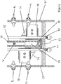
- FIG. 1 is an inventive linear selector 1, consisting of a fine selector 2 and a reversing switch 3, shown.
- the fine selector 2 has two rows of vertically arranged stage contacts 4 1 , 4 3 , 4 5 , ...; 5 0 , 5 2 , 5 4 , ...; on.
- a first row 40 carries the odd numbered stage contacts 4 1 , 4 3 , 4 5 , ... and a second row 50 carries the even numbered stage contacts 5 0 , 5 2 , 5 4 , ..., all in a wall 37 of the linear selector 1 are used.
- This wall 37 is formed as a segment of a cylinder, but may also consist of several rods arranged in a semicircle.
- the Maltese cross 8 is driven by a driver 9.
- the drive for the driver 9 is an electric motor (not shown here), which may be configured in the form of a three-phase motor.
- the linear selector 1 has a first diverter contact 10 and a second diverter contact 11.
- the Ableitessore 10, 11 parallel to each other, to a diverter switch, not shown here.
- the traction means 12 is mechanically coupled to a contact carriage 13.
- the traction means 12 may be a chain, a toothed belt or the like.
- a detailed representation of the contact carriage 13 is shown in FIG FIG. 2 shown in section.
- the contact carriage 13 carries a first contact arm 14 and a second contact arm 15. Each contact arm 14, 15 has a Gleitcardschreib 16.
- the contact carriage 13 can be moved with the traction means 12 in a vertical direction V in the linear selector 1 up and down.
- the first contact arm 14 contacts with the sliding contact pair 16 the odd-numbered stage contacts 4 1 , 4 3 , 4 5 ,...
- the second contact arm 15 with its sliding contact pair 16 contacts the even-numbered stage contacts 5 0 , 5 2 , 5 4 , ... of the linear selector 1.
- a driving pin 18 is arranged on the traction means 12, via which the contact carriage 13 is moved or taken away.
- the fine selector 2 a guide 19, by means of which the contact carriage 13 is guided in the movement in the vertical direction V.
- the linear selector 1 also consists of a reversing switch 3, which cooperates with the gear 6 via a shaft 20.
- a first contact fan 21 and a second contact fan 22 are arranged on the shaft 20.
- the first and the second contact compartments 21, 22 are mounted one above the other in the axial direction on the shaft 20 spaced from each other.
- the first contact fan 21 has a GleitCountsuper 24 and the second contact fan 22 also has a GleitCountschreib 24.
- the first contact fan 21 and the second contact fan 22 have the shape of a Circular segments, wherein on the segmental arch each sliding contact 24 is provided.
- the first contact compartments 21 are associated with three reversing contacts A, B, D, which are arranged along a circle segment arc K BAD , that they are contacted by Gleitcardcru 24 of the first contact fan 21 in its pivoting movement.
- the second contact fan 22 also three WenderAuthe B, C, D are assigned, which are arranged along a circle segment arc K DCB , that they are contacted by Gleitcardcru 24 of the second contact fan 22 in its pivoting movement.
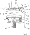
- FIG. 3 is a detailed view of the transmission 6 of the linear selector 1 shown.
- the transmission 6 consists essentially of a Geneva wheel 7, a first bevel gear 30 and a second bevel gear 31.
- the Geneva wheel 7 is connected in a rotationally fixed manner to the first bevel gear 30 via a connecting shaft 29.
- the second bevel gear 31 is mechanically connected in meshing engagement with the first bevel gear 30, wherein the second bevel gear 31 is seated on a Switzerlandstoffwelle 32.
- the Maltese wheel 7 consists of a Maltese cross 8, which sits non-rotatably on a disc 35. On a side facing away from the Maltese cross 8 side, the disc 35 carries a cam 25 on the circumference.
- the cam 25 cooperates with a groove 26 of a fork 27 of the shaft 20 of the first contact fan 21 and the second contact fan 22 of the reversing switch 3.
- the cam 25 engages in dependence on the rotational movement of the Geneva wheel 7 temporarily in the groove 26 of the fork 27 a. This happens when the Geneva wheel 7 reaches a certain position when turning.
- the pivoting movement in turn results in a pivoting movement of the first contact fan 21 and the second contact fan 22.
- the driver 9 is driven continuously.
- the rollers 28 fastened to it alternately engage with grooves 38 of the Maltese cross 8.
- the alternating engagement in the grooves 38 of the Maltese cross 8 results in a stepwise rotational movement of the Geneva wheel 7.
- the Geneva wheel 7 is rotatably connected via the connecting shaft 29 with the first bevel gear 30, so that the stepwise movement of the Geneva wheel 7 is transmitted to the first bevel gear 30.
- the first bevel gear 30 transmits the stepwise movement to the second bevel gear 31.
- the second bevel gear 31 is in mechanical connection with a Buchstoffwelle 32.
- the electrically conductive connection arises in each case by the Gleitcardcru 16 of the first contact arm 14 or the second contact arm 15 on the one hand, the odd-numbered stage contacts 4 1 , 4 third , 4 5 .... or the even-numbered stage contacts 5 0 , 5 2 , 5 4 , ... and on the other hand the Ableitcarde 10, 11 touch or contact.
- This embodiment ensures that at least one electrically conductive connection either between an odd-numbered stage contact 4 1 , 4 3 , 4 5 ,... And the first diverter contact 10 or an even-numbered stage contact 5 0 , 5 2 , 5 4 , the second diverter 11 is.
- the reversing switch 3 ensures with the first contact fan 21st and the second contact fan 22 is a permanent Potentialanlenkung the control winding, so that it is not separated at any time from the parent winding.
- Such reversing switch 3 with WenderAuthen on two levels are also referred to as double turner.
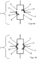
- the first contact fan 21 and the second contact fan 22 from the initial position in which the first contact fan 21, the first WenderURIe A and D and the second contact fan 22, the first WenderAuthe B and C electrically conductively connected to each other, pivoted.
- the first contact fan 21 and the second contact fan 22 first all WenderAuthe B, A, D of the first circle segment arc K BAD or all WenderAuthe D, C, B of the second circular segment arc K DCB electrically conductive and connect them together.
- first contact fan 21 and the second contact fan 22 are pivoted further until the first contact fan 21, the WenderAuthe A and B and the second contact fan 22, the WenderAuthe C and D electrically conductively interconnects, as in Figure 4c you can see.
Landscapes
- Transmission Devices (AREA)
- Structures Of Non-Positive Displacement Pumps (AREA)
- Mechanisms For Operating Contacts (AREA)
- Housings And Mounting Of Transformers (AREA)
- Details Of Connecting Devices For Male And Female Coupling (AREA)
Claims (10)
- Sélecteur linéaire (1) permettant la présélection sans fil des contacts à gradins (4, 5) d'un transformateur à gradins (100) comprenant un sélecteur fin (2) et un commutateur rotatif (3), le sélecteur fin (2) comportant des contacts à gradins impairs (41, 43, 45...) qui sont situés dans une première rangée (40) et des contacts à gradins pairs (50, 52, 54... ) qui sont situés dans une seconde rangée (50),
caractérisé en ce que
le sélecteur linéaire (1) porte une transmission (6) avec laquelle un unique coulisseau de contact (13) permet d'actionner directement les contacts à gradins impairs (41, 43, 45...) et les contacts à gradins pairs (50, 52, 54...) du sélecteur fin (2) ainsi qu'un premier éventail de contact (21) et un second éventail de contact (22) du commutateur rotatif (3) situés sur un arbre (20). - Sélecteur linéaire (1) conforme à la revendication 1, dans lequel la transmission (6) est constituée par une roue en croix de Malte (7), une première roue conique (30) et une seconde roue conique (31), la roue en croix de Malte (7) est reliée solidairement en rotation avec la première roue conique (30) par l'intermédiaire d'un arbre de liaison (29) et la seconde roue conique (31) est située sur un arbre de moyen de traction (32) et peut être entraînée au moyen de la première roue conique (30).
- Sélecteur linéaire (1) conforme à la revendication 2, dans lequel la roue en croix de Malte (7) est constituée par une croix de Malte (8) qui est montée solidairement en rotation sur un disque (35) qui, porte à sa périphérie, sur sa face située à l'opposé de la croix de Malte (8) une came (25) qui coopère avec une rainure (26) d'une fourche (27) de l'arbre (20) du premier éventail de contact (21) et du second éventail de contact (22) du commutateur rotatif (3).
- Sélecteur linéaire (1) conforme à la revendication 3, dans lequel en venant en prise dans la rainure (26) de la fourche (27) de l'arbre (20) du premier éventail de contact (21) et du second éventail de contact (22) du commutateur inverseur (3), la came (25) permet d'entraîner l'arbre (20) selon un mouvement de pivotement.
- Sélecteur linéaire (1) conforme aux revendications 1 à 4, dans lequel un élément de commande (9) tournant en continu porte plusieurs galets (26) qui coopèrent avec la croix de Malte (8) de la roue en croix de Malte (7) de façon à permettre d'obtenir un déplacement pas à pas de cette roue en croix de Malte (7).
- Sélecteur linéaire (1) conforme à la revendication 5, dans lequel le déplacement pas à pas de la roue en croix de Malte (7) peut être transmis par l'intermédiaire de l'arbre de liaison (29) à la première roue conique (30) et à la seconde roue conique (31), et le moyen de traction (12) du coulisseau de contact (13) peut être actionné pas à pas et linéairement par l'arbre (32) du moyen de traction.
- Sélecteur linéaire (1) conforme à la revendication 6, dans lequel l'élément de traction (12) comprend un boulon d'entraînement (18), et ce boulon d'entraînement (18) est relié mécaniquement solidairement au coulisseau de contact (13) de sorte que ce coulisseau de contact (13) puisse être déplacé en direction verticale par l'intermédiaire du moyen de traction (12).
- Sélecteur linéaire (1) conforme à l'une des revendications précédentes, dans lequel de coulisseau de contact (13) comprend un premier bras de contact (14) équipé d'une paire de contacts glissants (16) et un second bras de contact (15) équipé d'une paire de contacts glissants (16), et, le premier bras de contact (14) permet d'obtenir par sa paire de contacts glissants (16), une liaison électriquement conductrice entre les contacts à gradins impairs (41, 43, 45...) montés verticalement et un premier contact de décharge (10) tandis que le second bras de contact (15), permet d'obtenir par sa paire de contacts glissants (16) une liaison électriquement conductrice entre les contacts à gradins pairs (50, 52, 54...) montés verticalement et un second contact de décharge (11).
- Sélecteur linéaire (1) conforme à la revendication 8, dans lequel, le déplacement vertical pas à pas du coulisseau de contact (13) par l'intermédiaire de l'élément de traction (12), permet d'obtenir une liaison électriquement conductrice entre l'un des contacts à gradins impairs (41, 43, 45... ) et le premier contact de décharge (10) et/ou entre l'un des contacts à gradins pairs (50, 52, 54...) et le second contact de décharge (11).
- Sélecteur linéaire (1) conforme à l'une des revendications précédentes, dans lequel le premier éventail de contact (21) et le second éventail de contact (22) du commutateur rotatif (3) sont décalés axialement sur l'arbre (20), le premier éventail de contact (21) et le second éventail de contact (22) comprennent chacun une paire de contacts glissants (24), et, au premier éventail de contact (21) sont associés trois contacts rotatifs (B, A, D) situés dans le plan horizontal d'un premier arc de segment de cercle (KBAD) et au second éventail de contact (22) sont associés trois contacts rotatifs (D, C, B) situés dans le plan horizontal d'un second arc de segment de cercle (KDCB).
Applications Claiming Priority (2)
| Application Number | Priority Date | Filing Date | Title |
|---|---|---|---|
| DE102013102299.5A DE102013102299B4 (de) | 2013-03-08 | 2013-03-08 | Linearwähler |
| PCT/EP2014/051338 WO2014135302A1 (fr) | 2013-03-08 | 2014-01-23 | Sélecteur linéaire |
Publications (2)
| Publication Number | Publication Date |
|---|---|
| EP2965336A1 EP2965336A1 (fr) | 2016-01-13 |
| EP2965336B1 true EP2965336B1 (fr) | 2017-01-11 |
Family
ID=50023555
Family Applications (1)
| Application Number | Title | Priority Date | Filing Date |
|---|---|---|---|
| EP14701520.0A Active EP2965336B1 (fr) | 2013-03-08 | 2014-01-23 | Sélecteur lineaire |
Country Status (6)
| Country | Link |
|---|---|
| US (1) | US9570248B2 (fr) |
| EP (1) | EP2965336B1 (fr) |
| CN (1) | CN105027245B (fr) |
| DE (1) | DE102013102299B4 (fr) |
| UA (1) | UA115349C2 (fr) |
| WO (1) | WO2014135302A1 (fr) |
Families Citing this family (3)
| Publication number | Priority date | Publication date | Assignee | Title |
|---|---|---|---|---|
| DE102016116338A1 (de) | 2016-09-01 | 2018-03-01 | Stahl Gmbh | Schalteinrichtung zur Kontaktierung einer elektrischen Baugruppe |
| EP3989253B1 (fr) * | 2020-10-26 | 2026-03-25 | Hitachi Energy Ltd | Système de commande d'un interrupteur à vide pour un commutateur de dérivation de puissance, commutateur de dérivation de puissance et changeur de prises en charge |
| EP4084032B1 (fr) * | 2021-04-28 | 2025-06-04 | Hitachi Energy Ltd | Ensemble interrupteur à vide pour un commutateur de dérivation de puissance, commutateur de dérivation de puissance pour un commutateur de prises en charge de transformateur et commutateur de prises en charge de transformateur |
Family Cites Families (21)
| Publication number | Priority date | Publication date | Assignee | Title |
|---|---|---|---|---|
| DE580086C (de) * | 1931-10-02 | 1933-07-05 | Bernhard Jansen Dr Ing | Stufenwaehler |
| DE763245C (de) * | 1938-03-15 | 1954-03-22 | Siemens Schuckertwerke A G | Stufenschaltvorrichtung fuer Anzapftransformatoren |
| DE900248C (de) | 1943-01-17 | 1953-12-21 | Siemens Ag | Ohne Unterbrechung umschaltender doppelpoliger Wendeschalter fuer eine Transformatorstufenregeleinrichtung |
| FR956570A (fr) * | 1943-02-23 | 1950-02-02 | ||
| DE913933C (de) * | 1943-03-10 | 1954-06-21 | Siemens Ag | Stufenregeleinrichtung fuer Transformatoren |
| DE892176C (de) | 1943-05-20 | 1953-10-05 | Aeg | Waehler fuer unter Last regelbare Transformatoren |
| US4532386A (en) * | 1983-10-05 | 1985-07-30 | Rte Corporation | Dual voltage switch |
| US4562316A (en) * | 1984-06-07 | 1985-12-31 | Asea Electric, Inc. | High voltage linear tap changer |
| AT386091B (de) * | 1986-07-02 | 1988-06-27 | Elin Union Ag | Schaltanordnung fuer den wenderschalter eines stufenschalters fuer transformatoren |
| US5191179A (en) * | 1989-11-09 | 1993-03-02 | Cooper Power Systems, Inc. | Tap selector anti-arcing system |
| DE9308424U1 (de) * | 1992-10-16 | 1994-02-17 | Maschinenfabrik Reinhausen Gmbh, 93059 Regensburg | Stufenwähler mit Mehrfach-Grobwähler für Stufenschalter |
| CN1037040C (zh) * | 1993-05-06 | 1998-01-14 | 赖茵豪森机械制造公司 | 直接接触式单极分接开关 |
| DE19549238A1 (de) * | 1995-12-21 | 1997-06-26 | Aeg Tro Transformatoren Gmbh | Schrittschaltgetriebe für Lastwähler |
| CN2302587Y (zh) * | 1997-04-07 | 1998-12-30 | 常衍太 | 干式变压器有载开关 |
| DE19836463C1 (de) * | 1998-08-12 | 1999-10-21 | Reinhausen Maschf Scheubeck | Stufenschalter mit einem Vorwähler |
| US6825426B2 (en) * | 2002-10-02 | 2004-11-30 | Mcgraw-Edison Company | Make-before-break selector switch |
| CN1841583A (zh) * | 2005-03-28 | 2006-10-04 | 上海华明电力设备制造有限公司 | 组合式有载分接开关 |
| US7649147B2 (en) * | 2007-09-14 | 2010-01-19 | Riming Xiao | Off-circuit tap changer device |
| DE102009043171B4 (de) * | 2009-09-26 | 2014-11-20 | Maschinenfabrik Reinhausen Gmbh | Stufenschalter mit Vakuumschaltröhren |
| DE102010015051B4 (de) * | 2010-04-15 | 2012-06-14 | Maschinenfabrik Reinhausen Gmbh | Mechanischer Schaltkontakt |
| CN202711974U (zh) * | 2012-04-23 | 2013-01-30 | 莱茵豪森机械制造公司 | 由负载切换器和选级器构成的用于分级变压器的分接开关 |
-
2013
- 2013-03-08 DE DE102013102299.5A patent/DE102013102299B4/de not_active Expired - Fee Related
-
2014
- 2014-01-23 UA UAA201508570A patent/UA115349C2/uk unknown
- 2014-01-23 CN CN201480012897.8A patent/CN105027245B/zh active Active
- 2014-01-23 US US14/766,906 patent/US9570248B2/en active Active
- 2014-01-23 WO PCT/EP2014/051338 patent/WO2014135302A1/fr not_active Ceased
- 2014-01-23 EP EP14701520.0A patent/EP2965336B1/fr active Active
Non-Patent Citations (1)
| Title |
|---|
| None * |
Also Published As
| Publication number | Publication date |
|---|---|
| DE102013102299A1 (de) | 2014-09-11 |
| WO2014135302A1 (fr) | 2014-09-12 |
| EP2965336A1 (fr) | 2016-01-13 |
| US20160005554A1 (en) | 2016-01-07 |
| CN105027245A (zh) | 2015-11-04 |
| US9570248B2 (en) | 2017-02-14 |
| DE102013102299B4 (de) | 2014-12-04 |
| CN105027245B (zh) | 2017-09-26 |
| HK1214679A1 (zh) | 2016-07-29 |
| UA115349C2 (uk) | 2017-10-25 |
Similar Documents
| Publication | Publication Date | Title |
|---|---|---|
| EP3427284B1 (fr) | Changeur de prises en charge | |
| DE102009043171B4 (de) | Stufenschalter mit Vakuumschaltröhren | |
| EP0907192B1 (fr) | Sélecteur de prises | |
| EP2686856B1 (fr) | Changeur de prises en charge | |
| EP2862190B1 (fr) | Changeur de prises en charge | |
| DE102010015051B4 (de) | Mechanischer Schaltkontakt | |
| EP2891166B1 (fr) | Accumulateur de force pour un commutateur d'étage de charge | |
| DE3833126A1 (de) | Lastwaehler fuer stufentransformatoren | |
| DE102011113718A1 (de) | Laststufenschalter | |
| WO2008138430A1 (fr) | Dispositif de commutation | |
| EP2815413B1 (fr) | Commutateur de prises en charge avec au moins deux vacuostats et actionnement pour un commutateur de prises en charge avec au moins deux vacuostats | |
| WO2010149483A1 (fr) | Fenêtre d'inspection et borne de mise à la terre pour un ensemble haute tension | |
| EP2840282B1 (fr) | Actionneur comprenant des interrupteurs de fin de course | |
| EP2965336B1 (fr) | Sélecteur lineaire | |
| DE102016117786A1 (de) | Elektrischer Schalter | |
| DE2329707B2 (de) | Schalteinrichtung fuer einen zeitschalter | |
| DE102019130460A1 (de) | Laststufenschalter | |
| EP4042462B1 (fr) | Sélecteur pour changeur de prises en charge | |
| WO2009015995A1 (fr) | Actionneur de boîte de vitesses pour actionner un dispositif de commutation d'une boîte de vitesses | |
| DE102010050259B4 (de) | Umsteller für einen Stufentransformator | |
| WO2012097958A1 (fr) | Changeur de prise | |
| DE202011109824U1 (de) | Stufenschalter | |
| DE3139007C2 (de) | Vorrichtung zum Einstellen der Ausrichtung von Scheinwerfern, insbesondere von Kraftfahrzeugscheinwerfern | |
| WO2013092111A1 (fr) | Unité de commande pour un changeur de prises en charge | |
| WO2014048650A1 (fr) | Changeur de prises en charge muni d'un présélecteur |
Legal Events
| Date | Code | Title | Description |
|---|---|---|---|
| PUAI | Public reference made under article 153(3) epc to a published international application that has entered the european phase |
Free format text: ORIGINAL CODE: 0009012 |
|
| 17P | Request for examination filed |
Effective date: 20151008 |
|
| AK | Designated contracting states |
Kind code of ref document: A1 Designated state(s): AL AT BE BG CH CY CZ DE DK EE ES FI FR GB GR HR HU IE IS IT LI LT LU LV MC MK MT NL NO PL PT RO RS SE SI SK SM TR |
|
| AX | Request for extension of the european patent |
Extension state: BA ME |
|
| DAX | Request for extension of the european patent (deleted) | ||
| REG | Reference to a national code |
Ref country code: HK Ref legal event code: DE Ref document number: 1214679 Country of ref document: HK |
|
| GRAP | Despatch of communication of intention to grant a patent |
Free format text: ORIGINAL CODE: EPIDOSNIGR1 |
|
| INTG | Intention to grant announced |
Effective date: 20161017 |
|
| GRAS | Grant fee paid |
Free format text: ORIGINAL CODE: EPIDOSNIGR3 |
|
| GRAA | (expected) grant |
Free format text: ORIGINAL CODE: 0009210 |
|
| AK | Designated contracting states |
Kind code of ref document: B1 Designated state(s): AL AT BE BG CH CY CZ DE DK EE ES FI FR GB GR HR HU IE IS IT LI LT LU LV MC MK MT NL NO PL PT RO RS SE SI SK SM TR |
|
| REG | Reference to a national code |
Ref country code: GB Ref legal event code: FG4D Free format text: NOT ENGLISH |
|
| REG | Reference to a national code |
Ref country code: CH Ref legal event code: EP |
|
| REG | Reference to a national code |
Ref country code: AT Ref legal event code: REF Ref document number: 861953 Country of ref document: AT Kind code of ref document: T Effective date: 20170115 |
|
| REG | Reference to a national code |
Ref country code: IE Ref legal event code: FG4D Free format text: LANGUAGE OF EP DOCUMENT: GERMAN |
|
| REG | Reference to a national code |
Ref country code: DE Ref legal event code: R096 Ref document number: 502014002481 Country of ref document: DE |
|
| REG | Reference to a national code |
Ref country code: SE Ref legal event code: TRGR |
|
| REG | Reference to a national code |
Ref country code: FR Ref legal event code: PLFP Year of fee payment: 4 |
|
| REG | Reference to a national code |
Ref country code: LT Ref legal event code: MG4D |
|
| REG | Reference to a national code |
Ref country code: NL Ref legal event code: MP Effective date: 20170111 |
|
| PG25 | Lapsed in a contracting state [announced via postgrant information from national office to epo] |
Ref country code: BE Free format text: LAPSE BECAUSE OF NON-PAYMENT OF DUE FEES Effective date: 20170131 |
|
| PG25 | Lapsed in a contracting state [announced via postgrant information from national office to epo] |
Ref country code: NL Free format text: LAPSE BECAUSE OF FAILURE TO SUBMIT A TRANSLATION OF THE DESCRIPTION OR TO PAY THE FEE WITHIN THE PRESCRIBED TIME-LIMIT Effective date: 20170111 |
|
| PG25 | Lapsed in a contracting state [announced via postgrant information from national office to epo] |
Ref country code: GR Free format text: LAPSE BECAUSE OF FAILURE TO SUBMIT A TRANSLATION OF THE DESCRIPTION OR TO PAY THE FEE WITHIN THE PRESCRIBED TIME-LIMIT Effective date: 20170412 Ref country code: IS Free format text: LAPSE BECAUSE OF FAILURE TO SUBMIT A TRANSLATION OF THE DESCRIPTION OR TO PAY THE FEE WITHIN THE PRESCRIBED TIME-LIMIT Effective date: 20170511 Ref country code: HR Free format text: LAPSE BECAUSE OF FAILURE TO SUBMIT A TRANSLATION OF THE DESCRIPTION OR TO PAY THE FEE WITHIN THE PRESCRIBED TIME-LIMIT Effective date: 20170111 Ref country code: NO Free format text: LAPSE BECAUSE OF FAILURE TO SUBMIT A TRANSLATION OF THE DESCRIPTION OR TO PAY THE FEE WITHIN THE PRESCRIBED TIME-LIMIT Effective date: 20170411 Ref country code: FI Free format text: LAPSE BECAUSE OF FAILURE TO SUBMIT A TRANSLATION OF THE DESCRIPTION OR TO PAY THE FEE WITHIN THE PRESCRIBED TIME-LIMIT Effective date: 20170111 Ref country code: LT Free format text: LAPSE BECAUSE OF FAILURE TO SUBMIT A TRANSLATION OF THE DESCRIPTION OR TO PAY THE FEE WITHIN THE PRESCRIBED TIME-LIMIT Effective date: 20170111 |
|
| PG25 | Lapsed in a contracting state [announced via postgrant information from national office to epo] |
Ref country code: PL Free format text: LAPSE BECAUSE OF FAILURE TO SUBMIT A TRANSLATION OF THE DESCRIPTION OR TO PAY THE FEE WITHIN THE PRESCRIBED TIME-LIMIT Effective date: 20170111 Ref country code: PT Free format text: LAPSE BECAUSE OF FAILURE TO SUBMIT A TRANSLATION OF THE DESCRIPTION OR TO PAY THE FEE WITHIN THE PRESCRIBED TIME-LIMIT Effective date: 20170511 Ref country code: LV Free format text: LAPSE BECAUSE OF FAILURE TO SUBMIT A TRANSLATION OF THE DESCRIPTION OR TO PAY THE FEE WITHIN THE PRESCRIBED TIME-LIMIT Effective date: 20170111 Ref country code: ES Free format text: LAPSE BECAUSE OF FAILURE TO SUBMIT A TRANSLATION OF THE DESCRIPTION OR TO PAY THE FEE WITHIN THE PRESCRIBED TIME-LIMIT Effective date: 20170111 Ref country code: RS Free format text: LAPSE BECAUSE OF FAILURE TO SUBMIT A TRANSLATION OF THE DESCRIPTION OR TO PAY THE FEE WITHIN THE PRESCRIBED TIME-LIMIT Effective date: 20170111 |
|
| REG | Reference to a national code |
Ref country code: CH Ref legal event code: PL |
|
| REG | Reference to a national code |
Ref country code: DE Ref legal event code: R097 Ref document number: 502014002481 Country of ref document: DE |
|
| PG25 | Lapsed in a contracting state [announced via postgrant information from national office to epo] |
Ref country code: SK Free format text: LAPSE BECAUSE OF FAILURE TO SUBMIT A TRANSLATION OF THE DESCRIPTION OR TO PAY THE FEE WITHIN THE PRESCRIBED TIME-LIMIT Effective date: 20170111 Ref country code: CZ Free format text: LAPSE BECAUSE OF FAILURE TO SUBMIT A TRANSLATION OF THE DESCRIPTION OR TO PAY THE FEE WITHIN THE PRESCRIBED TIME-LIMIT Effective date: 20170111 Ref country code: CH Free format text: LAPSE BECAUSE OF NON-PAYMENT OF DUE FEES Effective date: 20170131 Ref country code: EE Free format text: LAPSE BECAUSE OF FAILURE TO SUBMIT A TRANSLATION OF THE DESCRIPTION OR TO PAY THE FEE WITHIN THE PRESCRIBED TIME-LIMIT Effective date: 20170111 Ref country code: RO Free format text: LAPSE BECAUSE OF FAILURE TO SUBMIT A TRANSLATION OF THE DESCRIPTION OR TO PAY THE FEE WITHIN THE PRESCRIBED TIME-LIMIT Effective date: 20170111 Ref country code: LI Free format text: LAPSE BECAUSE OF NON-PAYMENT OF DUE FEES Effective date: 20170131 |
|
| REG | Reference to a national code |
Ref country code: IE Ref legal event code: MM4A |
|
| PLBE | No opposition filed within time limit |
Free format text: ORIGINAL CODE: 0009261 |
|
| STAA | Information on the status of an ep patent application or granted ep patent |
Free format text: STATUS: NO OPPOSITION FILED WITHIN TIME LIMIT |
|
| PG25 | Lapsed in a contracting state [announced via postgrant information from national office to epo] |
Ref country code: MC Free format text: LAPSE BECAUSE OF FAILURE TO SUBMIT A TRANSLATION OF THE DESCRIPTION OR TO PAY THE FEE WITHIN THE PRESCRIBED TIME-LIMIT Effective date: 20170111 Ref country code: SM Free format text: LAPSE BECAUSE OF FAILURE TO SUBMIT A TRANSLATION OF THE DESCRIPTION OR TO PAY THE FEE WITHIN THE PRESCRIBED TIME-LIMIT Effective date: 20170111 Ref country code: LU Free format text: LAPSE BECAUSE OF NON-PAYMENT OF DUE FEES Effective date: 20170123 Ref country code: DK Free format text: LAPSE BECAUSE OF FAILURE TO SUBMIT A TRANSLATION OF THE DESCRIPTION OR TO PAY THE FEE WITHIN THE PRESCRIBED TIME-LIMIT Effective date: 20170111 |
|
| 26N | No opposition filed |
Effective date: 20171012 |
|
| REG | Reference to a national code |
Ref country code: FR Ref legal event code: PLFP Year of fee payment: 5 |
|
| REG | Reference to a national code |
Ref country code: BE Ref legal event code: MM Effective date: 20170131 |
|
| PG25 | Lapsed in a contracting state [announced via postgrant information from national office to epo] |
Ref country code: SI Free format text: LAPSE BECAUSE OF FAILURE TO SUBMIT A TRANSLATION OF THE DESCRIPTION OR TO PAY THE FEE WITHIN THE PRESCRIBED TIME-LIMIT Effective date: 20170111 Ref country code: IE Free format text: LAPSE BECAUSE OF NON-PAYMENT OF DUE FEES Effective date: 20170123 |
|
| REG | Reference to a national code |
Ref country code: HK Ref legal event code: GR Ref document number: 1214679 Country of ref document: HK |
|
| GBPC | Gb: european patent ceased through non-payment of renewal fee |
Effective date: 20180123 |
|
| PG25 | Lapsed in a contracting state [announced via postgrant information from national office to epo] |
Ref country code: MT Free format text: LAPSE BECAUSE OF FAILURE TO SUBMIT A TRANSLATION OF THE DESCRIPTION OR TO PAY THE FEE WITHIN THE PRESCRIBED TIME-LIMIT Effective date: 20170111 |
|
| PG25 | Lapsed in a contracting state [announced via postgrant information from national office to epo] |
Ref country code: GB Free format text: LAPSE BECAUSE OF NON-PAYMENT OF DUE FEES Effective date: 20180123 |
|
| PG25 | Lapsed in a contracting state [announced via postgrant information from national office to epo] |
Ref country code: HU Free format text: LAPSE BECAUSE OF FAILURE TO SUBMIT A TRANSLATION OF THE DESCRIPTION OR TO PAY THE FEE WITHIN THE PRESCRIBED TIME-LIMIT; INVALID AB INITIO Effective date: 20140123 |
|
| PG25 | Lapsed in a contracting state [announced via postgrant information from national office to epo] |
Ref country code: CY Free format text: LAPSE BECAUSE OF FAILURE TO SUBMIT A TRANSLATION OF THE DESCRIPTION OR TO PAY THE FEE WITHIN THE PRESCRIBED TIME-LIMIT Effective date: 20170111 |
|
| PG25 | Lapsed in a contracting state [announced via postgrant information from national office to epo] |
Ref country code: MK Free format text: LAPSE BECAUSE OF FAILURE TO SUBMIT A TRANSLATION OF THE DESCRIPTION OR TO PAY THE FEE WITHIN THE PRESCRIBED TIME-LIMIT Effective date: 20170111 |
|
| REG | Reference to a national code |
Ref country code: AT Ref legal event code: MM01 Ref document number: 861953 Country of ref document: AT Kind code of ref document: T Effective date: 20190123 |
|
| PG25 | Lapsed in a contracting state [announced via postgrant information from national office to epo] |
Ref country code: AT Free format text: LAPSE BECAUSE OF NON-PAYMENT OF DUE FEES Effective date: 20190123 |
|
| PG25 | Lapsed in a contracting state [announced via postgrant information from national office to epo] |
Ref country code: AL Free format text: LAPSE BECAUSE OF FAILURE TO SUBMIT A TRANSLATION OF THE DESCRIPTION OR TO PAY THE FEE WITHIN THE PRESCRIBED TIME-LIMIT Effective date: 20170111 |
|
| PGFP | Annual fee paid to national office [announced via postgrant information from national office to epo] |
Ref country code: BG Payment date: 20250121 Year of fee payment: 12 |
|
| P01 | Opt-out of the competence of the unified patent court (upc) registered |
Free format text: CASE NUMBER: APP_23377/2025 Effective date: 20250515 |
|
| PGFP | Annual fee paid to national office [announced via postgrant information from national office to epo] |
Ref country code: SE Payment date: 20260121 Year of fee payment: 13 |
|
| PGFP | Annual fee paid to national office [announced via postgrant information from national office to epo] |
Ref country code: DE Payment date: 20260120 Year of fee payment: 13 |
|
| PGFP | Annual fee paid to national office [announced via postgrant information from national office to epo] |
Ref country code: IT Payment date: 20260130 Year of fee payment: 13 |
|
| PGFP | Annual fee paid to national office [announced via postgrant information from national office to epo] |
Ref country code: FR Payment date: 20260121 Year of fee payment: 13 |
|
| PGFP | Annual fee paid to national office [announced via postgrant information from national office to epo] |
Ref country code: TR Payment date: 20260119 Year of fee payment: 13 |