EP2965423B1 - System und verfahren zum betreiben von niedrigleistungsschaltungen bei hohen temperaturen - Google Patents
System und verfahren zum betreiben von niedrigleistungsschaltungen bei hohen temperaturen Download PDFInfo
- Publication number
- EP2965423B1 EP2965423B1 EP14709842.0A EP14709842A EP2965423B1 EP 2965423 B1 EP2965423 B1 EP 2965423B1 EP 14709842 A EP14709842 A EP 14709842A EP 2965423 B1 EP2965423 B1 EP 2965423B1
- Authority
- EP
- European Patent Office
- Prior art keywords
- mode
- current
- high temperature
- temperature
- accordance
- Prior art date
- Legal status (The legal status is an assumption and is not a legal conclusion. Google has not performed a legal analysis and makes no representation as to the accuracy of the status listed.)
- Active
Links
Images
Classifications
-
- G—PHYSICS
- G05—CONTROLLING; REGULATING
- G05F—SYSTEMS FOR REGULATING ELECTRIC OR MAGNETIC VARIABLES
- G05F3/00—Non-retroactive systems for regulating electric variables by using an uncontrolled element, or an uncontrolled combination of elements, such element or such combination having self-regulating properties
- G05F3/02—Regulating voltage or current
-
- H—ELECTRICITY
- H03—ELECTRONIC CIRCUITRY
- H03K—PULSE TECHNIQUE
- H03K3/00—Circuits for generating electric pulses; Monostable, bistable or multistable circuits
- H03K3/01—Details
- H03K3/011—Modifications of generator to compensate for variations in physical values, e.g. voltage, temperature
Definitions
- This invention relates generally to low-power circuits and, particularly, to low-power circuits capable of operating at relatively high temperatures.
- circuits configured to function with low standby currents, e.g., standby current as low as 9 nA.
- standby current e.g., standby current as low as 9 nA.
- circuits are specified to function from -40 C to 85 C.
- extended temperature applications, referred to as “extended temperature” applications, require functionality at temperatures up to 150 C.
- leakage current increases exponentially. This results in circuit failure because all or most of the bias current flowing in the circuit can leak to ground and/or to the power supply rail.
- circuitry is provided in which the amount of current used is adjusted responsive to temperature.
- the circuitry is operable in two modes: low-power and high-temperature.
- a system for use in an integrated circuit includes first circuitry including first elements for operating in a low power mode; second circuitry including second elements for operating in a high-temperature mode; and one or more switching elements for selecting between the low power mode and the high temperature mode.
- a method for ensuring temperature-related circuit operation includes providing a temperature-based control signal; and switching circuit operation between first and second circuitry responsive to the temperature-based control signal, wherein the first circuitry includes first elements for operating in a low power mode and the second circuitry includes second elements for operating in a high-temperature mode.
- a control circuit measures the temperature and then automatically selects low-power or high-temperature mode, hysteresis could be added to avoid quickly toggling between the two modes as the sensed temperature crosses the trip point.
- circuitry is provided implementing low current standby operation.
- the circuitry is operable in a first, low-power mode in a standard temperature range and at least one second mode operable at temperatures that exceed the standard temperature range.
- An exemplary standard temperature range is -40 to 85 C.
- An exemplary extended temperature range is up to approximately 150 C.
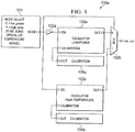
- FIGURE 1 a diagram of an exemplary circuit 100 for low-power and high-temperature modes in accordance with embodiments is shown.
- the circuit 100 includes a circuit 103a configured for low-power operation and a circuit 103b configured for high-temperature operation.
- the circuits 103a, 103b are oscillator circuits, although the circuits 103a, 103b can represent any circuit function that is sensitive to degradation at high temperature and where power consumption is a concern. Further, it is noted that, while only two discrete operating modes are discussed herein, other embodiments may include circuits functioning at a continuum of operating power levels as a function of temperature.
- a mode selection module 101 is provided to deliver a mode select signal or control to the circuit.
- the mode select module 101 may be implemented as any suitable circuit or control for selecting modes.
- the mode select module may be implemented as an on-chip fuse that is programmed to pre-select whether the part's operation will be optimized for low-power or high-temperature; a bond-wire that is placed during assembly; the output of a circuit that measures temperature and selects the mode of operation; or a mode register (that is controlled by the user's software).
- the mode select module 101 may be implemented as a manual control or as an automatic control, for example responsive to a temperature sensing function.
- the mode select input is provided to an inverter 102a, a multiplexer 102b's control input, and to the high-temperature circuit 103b.
- the low-power mode is selected if the mode select input is low (0) but the high-temperature mode is selected if the mode select input is high (1).
- the inverter 102a thus functions to enable the corresponding circuit 103a, 103b, while the multiplexer 102b selects its output.
- additional circuits 104a, 104b functioning as calibration units may be provided.
- the calibration units 104a, 104b may serve to "trim" the functions of the corresponding circuits 103, 103b respectively, that serve to optimize performance for the respective temperature range of operation
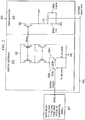
- FIGURE 2 illustrates another embodiment. More particularly, in FIGURE 2 , a single circuit 202 is provided which includes circuit elements that are sensitive to high temperatures.
- the mode select unit 201 is generally similar to the mode select unit 101 of FIGURE 1 . In this embodiment, however, the mode select signal may be an analog signal representing temperature.
- Circuit 202 is a function that is sensitive to disruption or degradation in operation due to leakage current present at high temperatures.
- a ramp generator 204 generates a ramp by creating a reference current 203 that is used to charge a capacitor 204a.
- resistor 203b couples to the circuit via switch 208b.
- desired currents can be used in 203 as generated by enabling a different resistor 203b (via switch 208a), rather than resistor 203a for the low current mode.
- desired currents can be generated that are larger than the leakage currents, although at the expense of higher power consumption.
- the charging capacitance value may likewise need to change.
- a second charging capacitor 204b may be provided for the high temperature, higher current mode, switchable using switch 210.
- the mode select signal 206 controls operation of switches 208a, 208b and 210 for changing the resistances and capacitances and thus the current usage, depending on temperature.
Landscapes
- Engineering & Computer Science (AREA)
- Physics & Mathematics (AREA)
- Electromagnetism (AREA)
- General Physics & Mathematics (AREA)
- Radar, Positioning & Navigation (AREA)
- Automation & Control Theory (AREA)
- Semiconductor Integrated Circuits (AREA)
- Electronic Switches (AREA)
Claims (15)
- System zur Sicherstellung des Betriebs von Niedrigleistungsschaltungen bei hoher Temperatur, das aufweist:eine integrierte Funktionseinheit, die ein Ausgangssignal erzeugt mit einem Oszillator (202), der eine Stromreferenz (203) und einen Sägezahngenerator (204) aufweist, wobei die Funktionseinheit gesteuert werden kann, um in einem ersten Modus und in einem zweiten Modus zu arbeiten, um das Ausgangssignal zu erzeugen, wobei der erste Modus ein Niedrigleistungsmodus ist und der zweite Modus ein Hochtemperaturmodus ist, wobei der Oszillator einen Steuereingang aufweist, der ein Steuersignal empfängt, und wobei in Abhängigkeit von dem Steuersignal Stromreferenz (203) und Sägezahngenerator (204) entweder in dem ersten oder zweiten Modus arbeiten, wobei der Oszillator (202) in dem Hochtemperaturmodus gesteuert wird, um Leckströme zu kompensieren; undeine Auswahleinheit (201) zur Steuerung der Funktionseinheit, um in dem Niedrigleistungsmodus oder dem Hochtemperaturmodus zu arbeiten.
- System gemäß Anspruch 1, wobei die Stromreferenz (203) steuerbar ist, um im ersten Modus einen ersten Strom und im zweiten Modus einen zweiten Strom zu erzeugen, wobei der zweite Strom in einem Hochtemperaturbereich Leckströme kompensiert.
- System gemäß Anspruch 2, wobei der Sägezahngenerator (204) einen ersten Ladekondensator (204a) aufweist, der eine Sägezahnrate im ersten Modus bestimmt, und einen zweiten Ladekondensator (204b) aufweist, der parallel zu dem ersten Ladekondensator (204a) geschaltet werden kann, um im zweiten Modus eine zweite Sägezahnrate zu bestimmen.
- System gemäß Anspruch 2 oder 3, das eine Schalteinheit (208) zur Auswahl eines ersten oder eines zweiten Widerstands aufweist, wobei der erste Widerstand den ersten Strom festlegt und der zweite Widerstand den zweiten Strom festlegt.
- System gemäß Anspruch 3, wobei die Stromreferenz (203) einen Stromspiegel aufweist.
- System gemäß Anspruch 5, wobei der Sägezahngenerator (204) derart mit dem Stromspiegel gekoppelt ist, dass durch den Stromspiegel ein Sägezahnstrom festgelegt wird.
- System gemäß einem der vorherigen Ansprüche, wobei die Auswahleinheit (201) eine Temperaturauswahlsteuereinheit ist.
- System gemäß einem der vorherigen Ansprüche 1 bis 6, wobei die Auswahleinheit (201) ein Verbindungsdraht ist.
- System gemäß einem der vorherigen Ansprüche 1 bis 6, wobei die Auswahleinheit (201) eine Modusregistersteuerung ist.
- System gemäß einem der vorherigen Ansprüche 1 bis 6, wobei die Auswahleinheit (201) eine Sicherung ist.
- Verfahren zur Sicherstellung temperaturbezogenen Schaltungsbetriebs, das aufweist:Bereitstellen eines temperaturbasierten Steuersignals;Bereitstellen eines Oszillators (202), der eine Stromreferenz (203) und einen Sägezahngenerator (204) zur Erzeugung eines Ausgangstaktsignals aufweist, wobei Stromreferenz (203) und Sägezahngenerator (204) gesteuert werden können, um in einem ersten oder zweiten Modus zu arbeiten,basierend auf dem Steuersignal Betreiben der Schaltung, um das Ausgangssignal in einem ersten oder zweiten Modus zu erzeugen, wobei der erste Modus ein Niedrigleistungsmodus ist und der zweite Modus ein Hochtemperaturmodus ist, wobei der Oszillator (202) in dem Hochtemperaturmodus gesteuert wird, um Leckströme zu kompensieren.
- Verfahren nach Anspruch 11, wobei Umschalten zwischen dem ersten und zweiten Modus Einregeln von Stromfluss, Spannungen oder Ladung für den Schaltungsbetrieb aufweist.
- Verfahren nach Anspruch 11 oder 12, das weiterhin Steuern der Stromreferenz (203) aufweist, um einen ersten Strom im ersten Modus und einen zweiten Strom im zweiten Modus zu erzeugen, wobei der zweite Strom Leckströme im Hochtemperaturbereich kompensiert.
- Verfahren nach Anspruch 13, wobei der Sägezahngenerator (204) einen ersten Ladekondensator (204a), der eine Sägezahnrate im ersten Modus bestimmt, und einen zweiten Ladekondensator (204b) aufweist, der parallel zu dem ersten Ladekondensator (204a) geschaltet werden kann, um im zweiten Modus eine zweite Sägezahnrate zu bestimmen.
- Verfahren gemäß Anspruch 13 oder 14, wobei eine Schalteinheit (201) einen ersten oder einen zweiten Widerstand auswählt, wobei der erste Widerstand den ersten Strom bestimmt und der zweite Widerstand den zweiten Strom bestimmt.
Applications Claiming Priority (2)
| Application Number | Priority Date | Filing Date | Title |
|---|---|---|---|
| US13/784,655 US8988134B2 (en) | 2013-03-04 | 2013-03-04 | System and method for operating low power circuits at high temperatures |
| PCT/US2014/018297 WO2014137666A1 (en) | 2013-03-04 | 2014-02-25 | System and method for operating low power circuits at high temperatures |
Publications (2)
| Publication Number | Publication Date |
|---|---|
| EP2965423A1 EP2965423A1 (de) | 2016-01-13 |
| EP2965423B1 true EP2965423B1 (de) | 2017-10-04 |
Family
ID=50272758
Family Applications (1)
| Application Number | Title | Priority Date | Filing Date |
|---|---|---|---|
| EP14709842.0A Active EP2965423B1 (de) | 2013-03-04 | 2014-02-25 | System und verfahren zum betreiben von niedrigleistungsschaltungen bei hohen temperaturen |
Country Status (7)
| Country | Link |
|---|---|
| US (1) | US8988134B2 (de) |
| EP (1) | EP2965423B1 (de) |
| KR (1) | KR20150128649A (de) |
| CN (1) | CN104685787B (de) |
| ES (1) | ES2654103T3 (de) |
| TW (1) | TWI638254B (de) |
| WO (1) | WO2014137666A1 (de) |
Families Citing this family (1)
| Publication number | Priority date | Publication date | Assignee | Title |
|---|---|---|---|---|
| US10879420B2 (en) | 2018-07-09 | 2020-12-29 | University Of Iowa Research Foundation | Cascaded superlattice LED system |
Family Cites Families (13)
| Publication number | Priority date | Publication date | Assignee | Title |
|---|---|---|---|---|
| US3440521A (en) | 1967-01-23 | 1969-04-22 | Westinghouse Electric Corp | Temperature control means |
| JPS55118207A (en) | 1979-03-05 | 1980-09-11 | Toshiba Corp | Non-linear type characteristic compensation system |
| US5526320A (en) * | 1994-12-23 | 1996-06-11 | Micron Technology Inc. | Burst EDO memory device |
| US6020792A (en) * | 1998-03-19 | 2000-02-01 | Microchip Technology Inc. | Precision relaxation oscillator integrated circuit with temperature compensation |
| US6191637B1 (en) * | 1999-03-05 | 2001-02-20 | National Semiconductor Corporation | Switched capacitor bias circuit for generating a reference signal proportional to absolute temperature, capacitance and clock frequency |
| US6342817B1 (en) * | 2000-10-06 | 2002-01-29 | Linear Technology Corporation | Precision oscillator circuits and methods with switched capacitor frequency control and frequency-setting resistor |
| KR100502971B1 (ko) | 2002-12-04 | 2005-07-22 | 주식회사 코아매직 | 온도 센서를 구비한 리프레쉬 동작용 클럭발생기 |
| US7123105B2 (en) | 2003-12-19 | 2006-10-17 | Infineon Technologies North American Corporation | Oscillator with temperature control |
| US7573250B2 (en) * | 2004-08-24 | 2009-08-11 | International Rectifier Corporation | Method and apparatus for calibrating a ramp signal |
| TWI387208B (zh) * | 2005-03-21 | 2013-02-21 | 整合裝置科技公司 | 用於單片式時脈產生器及時序/頻率參考器之低延遲的起動 |
| US7768342B1 (en) | 2008-05-23 | 2010-08-03 | Maxim Integrated Products | Bias circuit with non-linear temperature characteristics |
| US8134413B2 (en) * | 2009-10-27 | 2012-03-13 | Qualcomm Incorporated | Low-power oscillator |
| US8536932B2 (en) | 2011-07-12 | 2013-09-17 | Intel IP Corporation | Temperature compensation circuit |
-
2013
- 2013-03-04 US US13/784,655 patent/US8988134B2/en active Active
-
2014
- 2014-02-25 ES ES14709842.0T patent/ES2654103T3/es active Active
- 2014-02-25 WO PCT/US2014/018297 patent/WO2014137666A1/en not_active Ceased
- 2014-02-25 EP EP14709842.0A patent/EP2965423B1/de active Active
- 2014-02-25 KR KR1020157007936A patent/KR20150128649A/ko not_active Ceased
- 2014-02-25 CN CN201480002568.5A patent/CN104685787B/zh active Active
- 2014-03-03 TW TW103107074A patent/TWI638254B/zh active
Non-Patent Citations (1)
| Title |
|---|
| None * |
Also Published As
| Publication number | Publication date |
|---|---|
| TWI638254B (zh) | 2018-10-11 |
| WO2014137666A1 (en) | 2014-09-12 |
| TW201447532A (zh) | 2014-12-16 |
| CN104685787B (zh) | 2018-08-28 |
| US8988134B2 (en) | 2015-03-24 |
| ES2654103T3 (es) | 2018-02-12 |
| US20140247086A1 (en) | 2014-09-04 |
| EP2965423A1 (de) | 2016-01-13 |
| KR20150128649A (ko) | 2015-11-18 |
| CN104685787A (zh) | 2015-06-03 |
Similar Documents
| Publication | Publication Date | Title |
|---|---|---|
| US7705575B2 (en) | Standby regulator | |
| KR101387214B1 (ko) | 전류 제한 검출기 | |
| EP2076951B1 (de) | System und verfahren zur erkennung mehrerer strombegrenzungen | |
| US8531234B2 (en) | Temperature detection device | |
| US7274180B2 (en) | Constant voltage outputting method and apparatus capable of changing output voltage rise time | |
| EP3652611B1 (de) | Digitaler leistungsmultiplexer | |
| JP2019009633A (ja) | 半導体装置および電子制御ユニット | |
| KR101052384B1 (ko) | 집적회로의 정적 누설을 최소화하기 위한 시스템 및 방법 | |
| US8766679B1 (en) | Power on reset (POR) circuit | |
| US11967510B2 (en) | Chip, heating circuit and heating control method for chip | |
| US8040160B2 (en) | Driver arrangement and signal generation method | |
| Jo et al. | A design of boost converter with time-domain MPPT and digital self-tracking ZCD for thermoelectric energy harvesting applications | |
| US7453304B2 (en) | Integrated circuit and method for generating a clock signal | |
| TWI596984B (zh) | A Two-End Integrated Circuit with Time-Varying Voltage and Current Characteristics and Phase-Locked Power Supply | |
| US8988134B2 (en) | System and method for operating low power circuits at high temperatures | |
| JP6248926B2 (ja) | 半導体装置、半導体装置の電源制御方法及びセンサノード | |
| US20080048746A1 (en) | Hysteresis Comparator with Programmable Hysteresis Width | |
| US20220311439A1 (en) | Multiplexer circuit using a transmission gate circuit with a selectively boosted switch control signal | |
| CN107422770B (zh) | 一种带隙基准电压电路及其控制方法 | |
| CN107577261A (zh) | 一种温度控制开关电路 | |
| EP4035269B1 (de) | Por-schaltung | |
| CN104137416B (zh) | 电压检测电路和电子电路 | |
| JP2003087965A (ja) | 温度プロテクション回路および電子装置 | |
| JP2010066936A (ja) | 電子装置 |
Legal Events
| Date | Code | Title | Description |
|---|---|---|---|
| PUAI | Public reference made under article 153(3) epc to a published international application that has entered the european phase |
Free format text: ORIGINAL CODE: 0009012 |
|
| 17P | Request for examination filed |
Effective date: 20150330 |
|
| AK | Designated contracting states |
Kind code of ref document: A1 Designated state(s): AL AT BE BG CH CY CZ DE DK EE ES FI FR GB GR HR HU IE IS IT LI LT LU LV MC MK MT NL NO PL PT RO RS SE SI SK SM TR |
|
| AX | Request for extension of the european patent |
Extension state: BA ME |
|
| DAX | Request for extension of the european patent (deleted) | ||
| GRAP | Despatch of communication of intention to grant a patent |
Free format text: ORIGINAL CODE: EPIDOSNIGR1 |
|
| STAA | Information on the status of an ep patent application or granted ep patent |
Free format text: STATUS: GRANT OF PATENT IS INTENDED |
|
| INTG | Intention to grant announced |
Effective date: 20170421 |
|
| GRAS | Grant fee paid |
Free format text: ORIGINAL CODE: EPIDOSNIGR3 |
|
| GRAA | (expected) grant |
Free format text: ORIGINAL CODE: 0009210 |
|
| STAA | Information on the status of an ep patent application or granted ep patent |
Free format text: STATUS: THE PATENT HAS BEEN GRANTED |
|
| AK | Designated contracting states |
Kind code of ref document: B1 Designated state(s): AL AT BE BG CH CY CZ DE DK EE ES FI FR GB GR HR HU IE IS IT LI LT LU LV MC MK MT NL NO PL PT RO RS SE SI SK SM TR |
|
| REG | Reference to a national code |
Ref country code: GB Ref legal event code: FG4D |
|
| REG | Reference to a national code |
Ref country code: CH Ref legal event code: EP |
|
| REG | Reference to a national code |
Ref country code: AT Ref legal event code: REF Ref document number: 934909 Country of ref document: AT Kind code of ref document: T Effective date: 20171015 |
|
| REG | Reference to a national code |
Ref country code: IE Ref legal event code: FG4D |
|
| REG | Reference to a national code |
Ref country code: DE Ref legal event code: R096 Ref document number: 602014015339 Country of ref document: DE |
|
| REG | Reference to a national code |
Ref country code: NL Ref legal event code: FP |
|
| REG | Reference to a national code |
Ref country code: FR Ref legal event code: PLFP Year of fee payment: 5 |
|
| REG | Reference to a national code |
Ref country code: ES Ref legal event code: FG2A Ref document number: 2654103 Country of ref document: ES Kind code of ref document: T3 Effective date: 20180212 |
|
| REG | Reference to a national code |
Ref country code: LT Ref legal event code: MG4D |
|
| REG | Reference to a national code |
Ref country code: AT Ref legal event code: MK05 Ref document number: 934909 Country of ref document: AT Kind code of ref document: T Effective date: 20171004 |
|
| PG25 | Lapsed in a contracting state [announced via postgrant information from national office to epo] |
Ref country code: NO Free format text: LAPSE BECAUSE OF FAILURE TO SUBMIT A TRANSLATION OF THE DESCRIPTION OR TO PAY THE FEE WITHIN THE PRESCRIBED TIME-LIMIT Effective date: 20180104 Ref country code: LT Free format text: LAPSE BECAUSE OF FAILURE TO SUBMIT A TRANSLATION OF THE DESCRIPTION OR TO PAY THE FEE WITHIN THE PRESCRIBED TIME-LIMIT Effective date: 20171004 Ref country code: SE Free format text: LAPSE BECAUSE OF FAILURE TO SUBMIT A TRANSLATION OF THE DESCRIPTION OR TO PAY THE FEE WITHIN THE PRESCRIBED TIME-LIMIT Effective date: 20171004 Ref country code: FI Free format text: LAPSE BECAUSE OF FAILURE TO SUBMIT A TRANSLATION OF THE DESCRIPTION OR TO PAY THE FEE WITHIN THE PRESCRIBED TIME-LIMIT Effective date: 20171004 |
|
| PG25 | Lapsed in a contracting state [announced via postgrant information from national office to epo] |
Ref country code: GR Free format text: LAPSE BECAUSE OF FAILURE TO SUBMIT A TRANSLATION OF THE DESCRIPTION OR TO PAY THE FEE WITHIN THE PRESCRIBED TIME-LIMIT Effective date: 20180105 Ref country code: LV Free format text: LAPSE BECAUSE OF FAILURE TO SUBMIT A TRANSLATION OF THE DESCRIPTION OR TO PAY THE FEE WITHIN THE PRESCRIBED TIME-LIMIT Effective date: 20171004 Ref country code: RS Free format text: LAPSE BECAUSE OF FAILURE TO SUBMIT A TRANSLATION OF THE DESCRIPTION OR TO PAY THE FEE WITHIN THE PRESCRIBED TIME-LIMIT Effective date: 20171004 Ref country code: HR Free format text: LAPSE BECAUSE OF FAILURE TO SUBMIT A TRANSLATION OF THE DESCRIPTION OR TO PAY THE FEE WITHIN THE PRESCRIBED TIME-LIMIT Effective date: 20171004 Ref country code: BG Free format text: LAPSE BECAUSE OF FAILURE TO SUBMIT A TRANSLATION OF THE DESCRIPTION OR TO PAY THE FEE WITHIN THE PRESCRIBED TIME-LIMIT Effective date: 20180104 Ref country code: AT Free format text: LAPSE BECAUSE OF FAILURE TO SUBMIT A TRANSLATION OF THE DESCRIPTION OR TO PAY THE FEE WITHIN THE PRESCRIBED TIME-LIMIT Effective date: 20171004 Ref country code: IS Free format text: LAPSE BECAUSE OF FAILURE TO SUBMIT A TRANSLATION OF THE DESCRIPTION OR TO PAY THE FEE WITHIN THE PRESCRIBED TIME-LIMIT Effective date: 20180204 |
|
| REG | Reference to a national code |
Ref country code: DE Ref legal event code: R097 Ref document number: 602014015339 Country of ref document: DE |
|
| PG25 | Lapsed in a contracting state [announced via postgrant information from national office to epo] |
Ref country code: DK Free format text: LAPSE BECAUSE OF FAILURE TO SUBMIT A TRANSLATION OF THE DESCRIPTION OR TO PAY THE FEE WITHIN THE PRESCRIBED TIME-LIMIT Effective date: 20171004 Ref country code: EE Free format text: LAPSE BECAUSE OF FAILURE TO SUBMIT A TRANSLATION OF THE DESCRIPTION OR TO PAY THE FEE WITHIN THE PRESCRIBED TIME-LIMIT Effective date: 20171004 Ref country code: SK Free format text: LAPSE BECAUSE OF FAILURE TO SUBMIT A TRANSLATION OF THE DESCRIPTION OR TO PAY THE FEE WITHIN THE PRESCRIBED TIME-LIMIT Effective date: 20171004 Ref country code: CZ Free format text: LAPSE BECAUSE OF FAILURE TO SUBMIT A TRANSLATION OF THE DESCRIPTION OR TO PAY THE FEE WITHIN THE PRESCRIBED TIME-LIMIT Effective date: 20171004 |
|
| PLBE | No opposition filed within time limit |
Free format text: ORIGINAL CODE: 0009261 |
|
| STAA | Information on the status of an ep patent application or granted ep patent |
Free format text: STATUS: NO OPPOSITION FILED WITHIN TIME LIMIT |
|
| PG25 | Lapsed in a contracting state [announced via postgrant information from national office to epo] |
Ref country code: RO Free format text: LAPSE BECAUSE OF FAILURE TO SUBMIT A TRANSLATION OF THE DESCRIPTION OR TO PAY THE FEE WITHIN THE PRESCRIBED TIME-LIMIT Effective date: 20171004 Ref country code: SM Free format text: LAPSE BECAUSE OF FAILURE TO SUBMIT A TRANSLATION OF THE DESCRIPTION OR TO PAY THE FEE WITHIN THE PRESCRIBED TIME-LIMIT Effective date: 20171004 Ref country code: PL Free format text: LAPSE BECAUSE OF FAILURE TO SUBMIT A TRANSLATION OF THE DESCRIPTION OR TO PAY THE FEE WITHIN THE PRESCRIBED TIME-LIMIT Effective date: 20171004 |
|
| 26N | No opposition filed |
Effective date: 20180705 |
|
| REG | Reference to a national code |
Ref country code: CH Ref legal event code: PL |
|
| PG25 | Lapsed in a contracting state [announced via postgrant information from national office to epo] |
Ref country code: MC Free format text: LAPSE BECAUSE OF FAILURE TO SUBMIT A TRANSLATION OF THE DESCRIPTION OR TO PAY THE FEE WITHIN THE PRESCRIBED TIME-LIMIT Effective date: 20171004 |
|
| REG | Reference to a national code |
Ref country code: BE Ref legal event code: MM Effective date: 20180228 |
|
| PG25 | Lapsed in a contracting state [announced via postgrant information from national office to epo] |
Ref country code: CH Free format text: LAPSE BECAUSE OF NON-PAYMENT OF DUE FEES Effective date: 20180228 Ref country code: LI Free format text: LAPSE BECAUSE OF NON-PAYMENT OF DUE FEES Effective date: 20180228 Ref country code: LU Free format text: LAPSE BECAUSE OF NON-PAYMENT OF DUE FEES Effective date: 20180225 Ref country code: SI Free format text: LAPSE BECAUSE OF FAILURE TO SUBMIT A TRANSLATION OF THE DESCRIPTION OR TO PAY THE FEE WITHIN THE PRESCRIBED TIME-LIMIT Effective date: 20171004 |
|
| PG25 | Lapsed in a contracting state [announced via postgrant information from national office to epo] |
Ref country code: BE Free format text: LAPSE BECAUSE OF NON-PAYMENT OF DUE FEES Effective date: 20180228 |
|
| PG25 | Lapsed in a contracting state [announced via postgrant information from national office to epo] |
Ref country code: MT Free format text: LAPSE BECAUSE OF NON-PAYMENT OF DUE FEES Effective date: 20180225 |
|
| PG25 | Lapsed in a contracting state [announced via postgrant information from national office to epo] |
Ref country code: TR Free format text: LAPSE BECAUSE OF FAILURE TO SUBMIT A TRANSLATION OF THE DESCRIPTION OR TO PAY THE FEE WITHIN THE PRESCRIBED TIME-LIMIT Effective date: 20171004 |
|
| PG25 | Lapsed in a contracting state [announced via postgrant information from national office to epo] |
Ref country code: PT Free format text: LAPSE BECAUSE OF FAILURE TO SUBMIT A TRANSLATION OF THE DESCRIPTION OR TO PAY THE FEE WITHIN THE PRESCRIBED TIME-LIMIT Effective date: 20171004 |
|
| PG25 | Lapsed in a contracting state [announced via postgrant information from national office to epo] |
Ref country code: CY Free format text: LAPSE BECAUSE OF FAILURE TO SUBMIT A TRANSLATION OF THE DESCRIPTION OR TO PAY THE FEE WITHIN THE PRESCRIBED TIME-LIMIT Effective date: 20171004 Ref country code: HU Free format text: LAPSE BECAUSE OF FAILURE TO SUBMIT A TRANSLATION OF THE DESCRIPTION OR TO PAY THE FEE WITHIN THE PRESCRIBED TIME-LIMIT; INVALID AB INITIO Effective date: 20140225 Ref country code: MK Free format text: LAPSE BECAUSE OF NON-PAYMENT OF DUE FEES Effective date: 20171004 |
|
| PG25 | Lapsed in a contracting state [announced via postgrant information from national office to epo] |
Ref country code: AL Free format text: LAPSE BECAUSE OF FAILURE TO SUBMIT A TRANSLATION OF THE DESCRIPTION OR TO PAY THE FEE WITHIN THE PRESCRIBED TIME-LIMIT Effective date: 20171004 |
|
| P01 | Opt-out of the competence of the unified patent court (upc) registered |
Effective date: 20230528 |
|
| PGFP | Annual fee paid to national office [announced via postgrant information from national office to epo] |
Ref country code: NL Payment date: 20260121 Year of fee payment: 13 |
|
| PGFP | Annual fee paid to national office [announced via postgrant information from national office to epo] |
Ref country code: GB Payment date: 20260121 Year of fee payment: 13 |
|
| PGFP | Annual fee paid to national office [announced via postgrant information from national office to epo] |
Ref country code: ES Payment date: 20260302 Year of fee payment: 13 |
|
| PGFP | Annual fee paid to national office [announced via postgrant information from national office to epo] |
Ref country code: DE Payment date: 20260121 Year of fee payment: 13 Ref country code: IE Payment date: 20260123 Year of fee payment: 13 |
|
| PGFP | Annual fee paid to national office [announced via postgrant information from national office to epo] |
Ref country code: IT Payment date: 20260121 Year of fee payment: 13 |
|
| PGFP | Annual fee paid to national office [announced via postgrant information from national office to epo] |
Ref country code: FR Payment date: 20260121 Year of fee payment: 13 |