EP2965458B1 - Schaltung zur erzeugung schwankender abtastung von serieller datenübertragung - Google Patents
Schaltung zur erzeugung schwankender abtastung von serieller datenübertragung Download PDFInfo
- Publication number
- EP2965458B1 EP2965458B1 EP14711432.6A EP14711432A EP2965458B1 EP 2965458 B1 EP2965458 B1 EP 2965458B1 EP 14711432 A EP14711432 A EP 14711432A EP 2965458 B1 EP2965458 B1 EP 2965458B1
- Authority
- EP
- European Patent Office
- Prior art keywords
- period
- clock
- value
- length
- nibble
- Prior art date
- Legal status (The legal status is an assumption and is not a legal conclusion. Google has not performed a legal analysis and makes no representation as to the accuracy of the status listed.)
- Active
Links
Images





Classifications
-
- H—ELECTRICITY
- H04—ELECTRIC COMMUNICATION TECHNIQUE
- H04L—TRANSMISSION OF DIGITAL INFORMATION, e.g. TELEGRAPHIC COMMUNICATION
- H04L7/00—Arrangements for synchronising receiver with transmitter
- H04L7/0079—Receiver details
-
- H—ELECTRICITY
- H04—ELECTRIC COMMUNICATION TECHNIQUE
- H04L—TRANSMISSION OF DIGITAL INFORMATION, e.g. TELEGRAPHIC COMMUNICATION
- H04L7/00—Arrangements for synchronising receiver with transmitter
- H04L7/02—Speed or phase control by the received code signals, the signals containing no special synchronisation information
- H04L7/033—Speed or phase control by the received code signals, the signals containing no special synchronisation information using the transitions of the received signal to control the phase of the synchronising-signal-generating means, e.g. using a phase-locked loop
- H04L7/0331—Speed or phase control by the received code signals, the signals containing no special synchronisation information using the transitions of the received signal to control the phase of the synchronising-signal-generating means, e.g. using a phase-locked loop with a digital phase-locked loop [PLL] processing binary samples, e.g. add/subtract logic for correction of receiver clock
-
- H—ELECTRICITY
- H04—ELECTRIC COMMUNICATION TECHNIQUE
- H04L—TRANSMISSION OF DIGITAL INFORMATION, e.g. TELEGRAPHIC COMMUNICATION
- H04L7/00—Arrangements for synchronising receiver with transmitter
- H04L7/04—Speed or phase control by synchronisation signals
- H04L7/041—Speed or phase control by synchronisation signals using special codes as synchronising signal
- H04L7/044—Speed or phase control by synchronisation signals using special codes as synchronising signal using a single bit, e.g. start stop bit
-
- H—ELECTRICITY
- H04—ELECTRIC COMMUNICATION TECHNIQUE
- H04L—TRANSMISSION OF DIGITAL INFORMATION, e.g. TELEGRAPHIC COMMUNICATION
- H04L25/00—Baseband systems
- H04L25/38—Synchronous or start-stop systems, e.g. for Baudot code
- H04L25/40—Transmitting circuits; Receiving circuits
- H04L25/49—Transmitting circuits; Receiving circuits using code conversion at the transmitter; using predistortion; using insertion of idle bits for obtaining a desired frequency spectrum; using three or more amplitude levels ; Baseband coding techniques specific to data transmission systems
-
- H—ELECTRICITY
- H04—ELECTRIC COMMUNICATION TECHNIQUE
- H04L—TRANSMISSION OF DIGITAL INFORMATION, e.g. TELEGRAPHIC COMMUNICATION
- H04L25/00—Baseband systems
- H04L25/38—Synchronous or start-stop systems, e.g. for Baudot code
- H04L25/40—Transmitting circuits; Receiving circuits
- H04L25/49—Transmitting circuits; Receiving circuits using code conversion at the transmitter; using predistortion; using insertion of idle bits for obtaining a desired frequency spectrum; using three or more amplitude levels ; Baseband coding techniques specific to data transmission systems
- H04L25/4902—Pulse width modulation; Pulse position modulation
Definitions
- the present disclosure relates to a dithering circuit for serial data transmission and, in particular, to a dithering circuit for a J2716 Single Edge Nibble Transmission (SENT) protocol nibble period detection.
- SENT Single Edge Nibble Transmission
- the SAE J2716 SENT protocol is a point-to-point scheme for transmitting signal values, for example from a sensor to a controller. It requires three wires, wherein one wire is used as a signal line and the other two for a supply voltage and ground and provides for an asynchronous one-way voltage interface. It allows for high resolution data transmission with a lower system cost than available serial data solutions.
- a SENT protocol message encodes data values in the falling edge to falling edge period of the signal.
- the message is preceded for synchronization/calibration by a fixed length period which provides a 56 unit time (also known as "ticks") reference.
- Data values are encoded into nibbles using 12 to 27 unit times.
- the nibble period detector in a SENT receiver must use a relatively fast clock source to accurately decode the nibble time values.
- a SENT communication fundamental unit of time can be in the range of 3 ⁇ s to 10 ⁇ s, wherein the maximum allowed clock variation is ⁇ 20% from the nominal unit time.
- a nibble must be detected asynchronously.
- the protocol provides for a synchronization/calibration pulse which is defined to be 56 unit times long. The pulse starts with a falling edge and remains low for 5 or more unit times followed by pulse that fills the remainder of the 56 unit times (UT).
- a receiver can easily determine the respective unit time after receiving such a synchronization/calibration pulse.
- each data nibble is determined by a fixed start pulse (12 UT) followed by a data pulse whose length is defined by its actual value.
- the variable time portion defined by the nibble value N has a length of N * UT.
- EP 0 335 797 A1 discloses a method and apparatus to synchronize by reception of a local clock belonging to a communication network, in particular of a transport vehicle.
- a method for determining a unit time of a serial transmission protocol, wherein the serial transmission protocol defines a unit time (UT) by transmitting a calibration pulse having a predetermined length of N*UT and wherein a receiver is operated by system clock, includes: dividing the system clock by M, wherein M evenly divides N, and sampling a received data nibble length by using a dithered sampling clock.
- using the dithered sampling clock comprises dividing a number of clock cycles by N/M and dithering each N/M unit times based on a remainder from the division.
- a system for determining a unit time of a serial transmission protocol, wherein the serial transmission protocol defines a unit time (UT) by transmitting a calibration pulse having a predetermined length of N*UT and wherein a receiver is operated by system clock, includes: a clock divider for dividing the system clock by M, wherein M evenly divides N, and a detector for sampling a received data nibble length by using a dithered sampling clock.
- using the dithered sampling clock comprises dividing a number of clock cycles by N/M and dithering each N/M unit times based on a remainder from the division.
- a method for receiving a serial transmission includes detecting a falling edge; dividing a clock by M, where M evenly divides N, where N*UT is a length of a predetermined calibration pulse and UT is a unit time; counting clock cycles over the length of the calibration pulse; dividing the number of clock cycles by N/M to obtain a number of clock cycles per calibration period; dithering each N/M unit times proportionally based on the remainder of the number of clock cycles per calibration period; and detecting received data nibble periods based on the dithering.
- a period dithering technique is used in a nibble period detector. This allows the SENT protocol receiver to operate from a clock source that is a fraction of the required frequency. According to various embodiments, a SENT protocol receiver can be operated from a much lower clock frequency than usual high speed serial interfaces. This saves power in the end application. It also allows users to take advantage of, for example, an 8-MHz on-chip RC-oscillator source that is commonly available, for example on microcontrollers manufactured by Microchip Technology, Inc. According to various embodiments, the count period of the SENT nibble detection logic is automatically dithered to obtain greater accuracy from a lower frequency clock source.
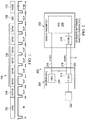
- the data message 100 includes a sync period 102 of 56 unit times; a status nibble 104 of 12-27 unit times; one to six data nibbles 106 of 12-27 unit times each; a CRC nibble of 12-27 unit times; and an optional pause period 110 of 12-768 unit times.
- FIG. 2 A diagram illustrating an exemplary SENT system in accordance with embodiments is shown in FIG. 2 .
- the system 200 includes one or more transmitters 202 and a receiver 204 communicatively coupled via supply voltage line 216, signal line 218, and ground line 220.
- the receiver 204 may include a supply voltage source 214 and one or more line filters 212.
- the receiver 204 may include a SENT receiver peripheral 222.
- the transmitter 202 may likewise include one or more line filters 210, as well as a control device such as a microcontroller unit 206.
- the system 200 may be embodied as a sensor system for an automotive engine or other system.
- the transmitter 202 may comprise an O2 sensor, an MAF sensor, a throttle position sensor, and the like.
- the receiver 204 in such embodiments may be an engine control unit.
- FIG. 3 A diagram of the SENT receiver peripheral 222 is shown in greater detail in FIG. 3 .
- the SENT peripheral receiver 222 includes receiver portion 303 and a control portion 301.
- the control portion 301 may include a plurality of control registers, as will be explained in greater detail below.
- the receiver portion 303 includes a Sync Period Detector 302 including a clock divider 304 and a sync timer 306.
- the SENT peripheral receiver further includes a Tick Period Generator 308, a Nibble Period Detector 310, and Control and Error Detection module 312.
- the SENTCON1 control register 316 may be used to select a particular mode of operation. For example, in embodiments in which the peripheral is a transceiver, the SENTCON1 control register 316 may be used to select whether the peripheral is operating in a transmit or receive mode.
- the SENTCON2 control register 318 and the SENTCON3 control register 320 may be used in a receive mode to define the maximum sync period time and the minimum sync period time, respectively. In receive mode, the registers may be referred to as SYNCMAX and SYNCMIN, respectively.
- a receiver according to various embodiments can be integrated into a microcontroller or can be combined with a transmitter to form a transceiver which could also be integrated into a microcontroller.
- the SENTSTAT control register 322 may be used to receive status messages from the control and error detection module 312.
- the SENTSYNC control register 324 may be used to receive the captured sync period that sets the period for the Tick Period Generator 308. In receive mode, the register may be referred to as the SYNCTIME register.
- the Sync Period Detector 302 In order to receive a SENT message, the Sync Period Detector 302 must first measure the time of the sync period 102, which as mentioned above is always 56 unit times (ticks) in duration. Specifically, the Sync Period Detector 302 must determine the number of CPU clock cycles in one 56 tick period. Once the sync period time is known, this data can be used by the Tick Period Generator 308 to determine the length of each incoming data nibble. The nibble data value is encoded in the amount of time between falling edges and can vary between 12 and 27 tick times.
- One method of making this sync period measurement is to divide the CPU clock by 56 and then count the number of divided clocks that occur during an incoming sync period. This resulting value then represents the number of CPU clocks in 1 tick time and can be used as a count period for Tick Period Generator 308 which measures the length of the incoming data nibbles.
- Tick Period Generator 308 which measures the length of the incoming data nibbles.
- the clock divider 304 of the Sync Period Detector 302 divides the CPU clock by 7 or 14 instead. Note that these divide values are evenly divisible into 56. So, the Sync Timer 306 of the Sync Period Detector 302 will count the number of CPU clocks in 8 or 4 tick times, respectively.
- embodiments In order to increase the accuracy of the nibble length measurement, embodiments 'dither' the period value used by the Tick Period Generator 308.
- the Sync Period Detector 302 has two functions. First, it validates that a period of time within a SENT message is Sync period and not a nibble period. Second, the Sync Period Detector 302 captures the actual Sync period time value for use by the Tick Period Generator 308. The Sync Period Detector may operate at all times during message reception. This may allow the receiver to re-synchronize at any time within a SENT message frame.
- the Sync Period Detector 302 has a dedicated timer 306 that is reset on every falling edge of the SENT message.
- the SYNCMIN[15:0] 320 and SYNCMAX[15:0] 318 control registers allow user software to configure a time window for the expected Sync period. These registers are configured with the minimum and maximum times expected for a valid Sync period.
- the Sync period timer contains a value between SYNCMIN and SYNCMAX, then the time period is treated as a valid Sync period.
- the Sync period timer value is captured in the SENTSYNC register 324.
- the value in the SENTSYNC register 324 is used by the Tick Period Generator 308. In addition, this value allows user software to compare the present Sync period time with those of prior messages.
- the SENT protocol allows no more than 1.5625% (1 in 64) timing variation between successive messages.
- the receiver When a valid sync period has been received, the receiver will expect 3 - 8 nibble periods to follow containing 12-27 tick periods each.
- the Tick Period Generator 308 uses the time value captured and stored in the SENTSYNC register 324 to determine the time period for TTICK.
- the Tick Period Generator 302 is active when a valid time between SYNCMIN and SYNCMAX has been detected.
- the Nibble Period Counter 310 uses a clock generated by the Tick Period Generator 308 and determines the amount of time actually elapsed during a nibble period.
- the minimum nibble period is 12 ticks for a data value of'0' and the maximum nibble period is 27 ticks for a data value of '15'.
- the Nibble Period Counter 310 removes this offset of 12 ticks and provides the actual nibble data value in the SENTDATA register 326.
- reception of a nibble data value occurs for the following conditions: a valid Sync period within the valid time window has been detected; fewer than 8 nibbles have been received since the last Sync period; and a falling edge has been detected.
- the time since the last falling edge is at least 12 tick times, but no more than 27 tick times.
- the receiver configuration requires knowledge of the nominal tick period sent by the transmitter, TTICK and the Input clock frequency to the SENT Protocol Receiver, Fclk.
- the input clock period to the receiver should be at least 1/8th the tick period, TTICK, or smaller. This will provide a captured value in the SENTSYNC register that is at least 64.
- the SENT protocol requires software verify that the length of the sync period does not change more than 1 in 64 between messages.
- the receiver clock frequency, Fclk is either Fcy or Fcy/4 depending on the setting of a SENTCON1.PS control bit.
- the module will produce an interrupt event when a valid sync period has occurred followed by 3- 8 valid nibble time periods.
- user software may read the status nibble, CRC nibble, and the 1 - 6 data nibbles from the SENTDATA register.
- the J2716 specification requires that the Sync period of the SENT data frame varies by no more than 1.5625% (1 in 64) between consecutive data frames. To verify this condition is met, user software should save the value captured in SENTSYNC after each data frame is received. The old value can then be compared to the value received during the next data frame.
- the Sync Period Detector 302 is a dedicated timebase with a time window comparison function and a time capture function.
- the Sync Period Detector logic operates on every falling edge of received data input. This allows the Sync Period Detector to resynchronize to a data frame at any time.
- the Sync Period Detector 302 has a 16-bit timebase The sync period timebase is compared to the two values, SYNCMIN and SYNCMAX. In some embodiments, the Sync Period Detector 302 will produce a synchronization event signal for the rest of the module to use on the following events: a falling edge has been detected on the SENT data input AND a true comparison of the timebase with SYNCMIN has occurred since the last falling edge, AND a true timebase comparison with SYNCMAX has NOT occurred since the last falling edge.
- the sync period timebase value is captured in the SENTSYNC register 324 and a SENTSTAT.SYNC bit is set At this time, the receiver will begin looking for data nibble time periods that are 12-27 ticks in length.
- the window comparison described above is performed; the sync period timebase is reset; and the time base and time window comparison logic for the SYNCMIN and SYNCMAX registers are reset to prepare for the next window comparison.
- the timebase is reset to '0'.
- the timebase remains at '0' until another falling edge is dctcctcd.
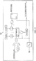
- FIG. 4 A conceptual exemplary block diagram of the Sync Period Detector 302 is shown in FIG. 4 .
- the timing for the detection of a valid synchronization period is shown in FIG. 5 . It is assumed that the valid sync period was preceded by a nibble period which is much shorter than a sync period. Therefore, the sync period timebase has been counting since the last detected falling edge.
- the timebase is reset to 0 when the first falling edge is detected.
- the second falling edge falls within the window of SYNCMIN and SYNCMAX, so SYNC is set and the timebase value is captured in SENTSYNC.
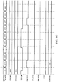
- FIG. 5B shows the timing for successive periods that are longer than the time of a valid sync period.
- the sync period timebase is held in Reset once a match with SYNCMAX occurs. No capture value is stored in the SENTSYNC register.
- FIG. 5C shows the timing for successive periods that are shorter than SYNCMIN.
- the sync period time- base is reset on each detected falling edge and no capture value is stored in the SENTSYNC register.
- the Tick Period Generator contains a 13-bit timebase.
- the count period for this timebase is set by the SENTSYNC[15:3] value.
- the period of a valid sync pulse is 56 tick times (It is noted that in other embodiments, the clock may be divided by a number other than 7).
- the value of SENTSYNC[15:3] represents the number of upbm_fsm_clk cycles in one tick period of the SENT protocol. This value can be used as a divider value for the Tick Period Generator timebase.
- the value of SENTSYNC[15:4] represents the number of upbm_fsm_clk cycles in 1/2 of a tick period.
- the Tick Period Generator 308 operates as follows:
- the count period of the Tick Period Generator timebase is dithered over a period of 4 count cycles.
- the SENTSYNC register 324 is loaded with the captured sync period from the sync timer 306. As noted above, this is the number of clock cycles in a number of sync periods. For example, in some embodiments, where the number of unit times in a sync period is 56 and is divided by 7, this number is 8.
- the dithering of the timebase period may be performed based on the value of the SENTSYNC[2:1] register as follows:
- FIG. 6 represents the SENTSYNC register 324 which uses the SENTSYNC[15:3] bits divided by 8 to obtain the number of cycles in a single sync period, SYNCTIME. The remaining, least significant bits provide the remainder and are thus used to determine the dithering, which results in a proportional, averaged over time, lengthening of the timebase period.
- FIG. 7 shows the timing for the Tick Period Generator 324.
- t1 is the count period determined by SENTSYNC[15:4] and t2 is the count period determined by SENTSYNC[15:3].
- the Nibble Period Counter 310 works along with the Tick Period Generator to determine the data value of each nibble.
- the Nibble Period Counter 310 has a 4-bit counter. If the macro is in a state in which nibble data is expected to be received, the Nibble Period Counter 310 will count pulses from the Tick Period Generator 324.
- FIG. 7 also shows the timing for the Nibble Period Counter 310. After a falling edge of the SENT data input, the Nibble Period Counter 310 is first configured to count 12 clocks from the Tick Period Generator 324. No further falling edges should occur on the SENT data input during this time. After 12 clocks have been counted, the counter is reset and will count clocks from the Tick Period Generator 324 until another falling edge is detected on the SENT data input
- the count value is captured for storage in the appropriate data register. Secondly, the counter is reset to prepare for the next nibble data period.
- the nibble data should be set to '0' and a framing error should be generated.
- the Nibble Period Counter 310 may be held in Reset until another valid sync period is found and the module is in a state to receive nibble data again.
- Each data nibble is stored in the appropriate 4-bit SENTDATA register location as it is received. Old nibble data must be read before a new nibble value is received.
- the SENTCON1.NIBCNT[2:0] control bits set the number of expected data nibbles to be received in a data frame.
- the DATA2 - DATA6 fields in the SENTDATA register may be skipped and not written by the module depending on the NIBCNT[2:0] setting.
- the SENT receive peripheral's clock divider 304 Upon detection of a falling edge and, depending on the embodiment, one or more other status indicia (step 802), the SENT receive peripheral's clock divider 304 will divide the sync period length (N unit times or ticks) by a number M, preferably where M divides N evenly, to obtain a number of sync periods K.
- the number of clock cycles C per sync period is then obtained (step 808).
- the number of clock cycles counted may be divided by the number K. Based on the remainder (if any), this number is dithered proportionally so that a predetermined number of the next K unit times are C cycles in length and a predetermined number are C + (remainder) unit times in length.
- the number of cycles K*C is loaded to the Tick Period Generator 308 and the SENTSYNC control register 324, as discussed above.
- the number C is obtained by examining the appropriate most significant bits of the SENTSYNC register.
- the least significant bits of the Sync Period Detector 306 are examined and the dithering is based on the result.
- the Nibble Period Detector 310 then detects nibbles based upon the Tick Periods lengths received from the Tick Period Generator, as discussed above (step 812).
- the terms “comprises,” “comprising,” “includes,” “including,” “has,” “having,” or any other variation thereof, are intended to cover a non-exclusive inclusion.
- a process, product, article, or apparatus that comprises a list of elements is not necessarily limited only those elements but may include other elements not expressly listed or inherent to such process, process, article, or apparatus.
Landscapes
- Engineering & Computer Science (AREA)
- Computer Networks & Wireless Communication (AREA)
- Signal Processing (AREA)
- Synchronisation In Digital Transmission Systems (AREA)
Claims (15)
- Verfahren zum Bestimmen einer Zeiteinheit eines seriellen Übertragungsprotokolls, wobei das serielle Übertragungsprotokoll eine Zeiteinheit UT definiert, indem ein Kalibrierungsimpuls (102) mit einer vorbestimmten Länge von N * UT gesendet wird und wobei ein Empfänger (204) von einem Systemtakt betrieben wird, wobei das Verfahren aufweist:Teilen des Systemtakts durch M, wobei M N gleichmäßig teilt,Messen eines Kalibrierungsimpuls- (102) Längenwerts unter Verwendung des geteilten Systemtakts;Bestimmen einer Anzahl von Systemtaktimpulsen pro Zeiteinheit aus dem gemessenen Kalibrierungsimpulswert;Abtasten einer empfangenen Daten-Nibble-Länge unter Verwendung eines durch einen Taktteiler vom Systemtakt abgeleiteten Abtasttakts, wobei der Abtasttakt eine durch den Taktteiler festgelegte variable Periode aufweist, wobei ein erster Periodenwert für eine erste Anzahl von Zählperioden verwendet wird und ein zweiter Periodenwert für eine zweite Zählperiode verwendet wird, um eine durchschnittliche Zählperiode zu erzeugen, wobei eine Addition der Anzahl der ersten Zählperioden und der Anzahl der zweiten Zählperioden gleich dem bestimmten Kalibrierungsimpulslängenwert ist, undwobei das serielle Übertragungsprotokoll eine Vielzahl von nachfolgenden Daten-Nibble-Impulsen (104, 106, 108) überträgt, wobei jeder Daten-Nibble-Wert in eine Länge eines Impulses codiert ist, wobei die Länge durch Vielfache der Zeiteinheit UT definiert ist und wobei eine Länge eines Daten-Nibble-Impulses (104, 106, 108) oder des Kalibrierungsimpulses (102) durch die Zeit zwischen zwei fallenden Flanken eines seriellen Übertragungssignals definiert ist.
- Verfahren gemäß Anspruch 1, wobei jeder Daten-Nibble-Impuls (104, 106, 108) eine erste Daten-Nibble-Periode auf einem ersten Logikpegel mit einer festen Länge aufweist, gefolgt von einer zweiten Daten-Nibble-Periode auf einem zweiten Logikpegel mit einer variablen Länge, wobei die Länge der zweiten Daten-Nibble-Periode vom Daten-Nibble-Wert abhängt.
- Verfahren gemäß einem der vorhergehenden Ansprüche, wobei N = 56 und M = 7 oder wobei N = 56 und M = 14.
- Verfahren gemäß einem der vorhergehenden Ansprüche 1 bis 2, wobei N = 56 und M = 28.
- Verfahren gemäß einem der vorhergehenden Ansprüche, wobei ein Periodenwert eines durch den Systemtakt getakteten Abtasttaktperiodengenerators (308) gedithert wird.
- Verfahren gemäß einem der vorhergehenden Ansprüche, wobei der Systemtaktteiler einen Abtasttaktperiodengenerator (308) aufweist, der durch den Systemtakt getaktet wird, der zum Bestimmen der Zeiteinheit verwendet wird, und wobei ein Periodenzeitgeber des Abtasttaktperiodengenerators (308) für drei Zeiträume mit dem ersten Periodenwert X = 7 und für einen Zeitraum mit dem zweiten Periodenwert X = 8 geladen wird, um die durchschnittliche Zählperiode zu erzeugen.
- Verfahren gemäß einem der vorhergehenden Ansprüche 1 bis 5, wobei das Verwenden des Abtasttakts das Teilen einer gemessenen Anzahl von Taktzyklen des Kalibrierungsimpulses (102) unter Verwendung des mittels N/M geteilten Systemtakts und Dithering jeder N/M Zeiteinheiten basierend auf einem Rest des Teilens aufweist.
- System zum Bestimmen einer Zeiteinheit eines seriellen Übertragungsprotokolls, wobei das serielle Übertragungsprotokoll eine Zeiteinheit UT definiert, indem ein Kalibrierungsimpuls (102) mit einer vorbestimmten Länge von N * UT gesendet wird und wobei ein Empfänger (204) durch einen Systemtakt betrieben wird, wobei das System aufweist:einen Taktteiler (304) zum Teilen des Systemtakts durch M, wobei M N gleichmäßig teilt,einen Zeitgeber (306), der ausgebildet ist, um einen Kalibrierungsimpulslängenwert unter Verwendung des geteilten Systemtakts zu messen, wobei das System weiterhin ausgebildet ist, um eine Anzahl von Systemtaktimpulsen pro Zeiteinheit aus dem gemessenen Kalibrierungsimpulslängenwert zu bestimmen;einen Zeiteinheitperiodengenerator (308), der einen Taktteiler aufweist und ausgebildet ist, um einen Abtasttakt unter Verwendung des Systemtakts mit einer variablen Periode zu erzeugen, indem der Taktteiler so programmiert wird, dass er einen ersten Periodenwert für eine erste Anzahl von Zählperioden und einen zweiten Periodenwert für die zweite Zählperiode verwendet, um eine durchschnittliche Zählperiode zu erzeugen, wobei die Addition der Anzahl der ersten Zählperioden und der Anzahl der zweiten Zählperioden gleich dem gemessenen Kalibrierungsimpulslängenwert ist; undeinen Detektor (310) zum Abtasten einer empfangenen Daten-Nibble-Länge unter Verwendung des Abtasttakts, wobei das serielle Übertragungsprotokoll eine Vielzahl von nachfolgenden Daten-Nibble-Impulsen (104, 106, 108) überträgt, wobei jeder Daten-Nibble-Wert in eine Länge eines Impulses codiert ist, wobei die Länge durch Vielfache der Zeiteinheit UT definiert ist und wobei eine Länge eines Daten-Nibble-Impulses (104, 106, 108) oder des Kalibrierungsimpulses (102) durch die Zeit zwischen zwei fallenden Flanken eines seriellen Übertragungssignals definiert ist.
- System gemäß Anspruch 8, wobei jeder Daten-Nibble-Impuls (104, 106, 108) eine erste Daten-Nibble-Periode auf einem ersten Logikpegel mit einer festen Länge aufweist, gefolgt von einer zweiten Daten-Nibble-Periode auf einem zweiten Logikpegel mit einer variablen Länge, wobei die Länge der zweiten Daten-Nibble-Periode vom Daten-Nibble-Wert abhängt.
- System gemäß einem der vorhergehenden Ansprüche 8 bis 9, wobei N = 56 und M = 7 oder N = 56 und M = 14.
- System gemäß einem der vorhergehenden Ansprüche 8 bis 9, wobei N = 56 und M = 28.
- System gemäß einem der vorhergehenden Ansprüche, das einen Abtasttaktperiodengenerator (308) aufweist, der durch den Systemtakt getaktet ist, wobei ein Periodenwert des Abtasttaktperiodengenerators (308) gedithert wird.
- System gemäß einem der vorhergehenden Ansprüche 8 bis 12, wobei der Zeiteinheitperiodengenerator (308) ausgebildet ist, um eine Zeiteinheit zu bestimmen, und einen Periodenzeitgeber aufweist, der für drei Zeitperioden mit dem ersten Periodenwert X = 7 und für eine Zeitperiode mit dem zweiten Periodenwert X = 8 geladen wird, um die durchschnittliche Zählperiode zu erzeugen.
- System gemäß einem der vorhergehenden Ansprüche 8 bis 12, ausgebildet zum Teilen einer gemessenen Anzahl von Taktzyklen des Kalibrierungsimpulses unter Verwendung des mittels N/M geteilten Systemtakts und Dithering jeder N/M Zeiteinheiten basierend auf einem Rest des Teilens.
- Verfahren zum Empfangen einer seriellen Übertragung, das aufweist:Erkennen einer fallenden Flanke;Abtasten einer eingehenden Übertragung unter Verwendung des Abtasttakts, der durch ein Verfahren gemäß einem der vorhergehenden Ansprüche 1 bis 7 erzeugt wurde.
Applications Claiming Priority (3)
| Application Number | Priority Date | Filing Date | Title |
|---|---|---|---|
| US201361775355P | 2013-03-08 | 2013-03-08 | |
| US14/197,812 US9054851B2 (en) | 2013-03-08 | 2014-03-05 | Dithering circuit for serial data transmission |
| PCT/US2014/021005 WO2014138334A1 (en) | 2013-03-08 | 2014-03-06 | Dithering circuit for serial data transmission |
Publications (2)
| Publication Number | Publication Date |
|---|---|
| EP2965458A1 EP2965458A1 (de) | 2016-01-13 |
| EP2965458B1 true EP2965458B1 (de) | 2020-12-02 |
Family
ID=51487807
Family Applications (1)
| Application Number | Title | Priority Date | Filing Date |
|---|---|---|---|
| EP14711432.6A Active EP2965458B1 (de) | 2013-03-08 | 2014-03-06 | Schaltung zur erzeugung schwankender abtastung von serieller datenübertragung |
Country Status (6)
| Country | Link |
|---|---|
| US (1) | US9054851B2 (de) |
| EP (1) | EP2965458B1 (de) |
| KR (1) | KR20150128658A (de) |
| CN (1) | CN104969507B (de) |
| TW (1) | TWI602046B (de) |
| WO (1) | WO2014138334A1 (de) |
Families Citing this family (9)
| Publication number | Priority date | Publication date | Assignee | Title |
|---|---|---|---|---|
| DE102014116909B4 (de) * | 2014-11-19 | 2016-07-28 | Infineon Technologies Ag | Empfänger, Sender, Verfahren zum Wiedergewinnen eines zusätzlichen Datenwerts aus einem Signal und Verfahren zum Übertragen eines Datenwerts und eines zusätzlichen Datenwerts in einem Signal |
| JP2016197807A (ja) * | 2015-04-03 | 2016-11-24 | 株式会社デンソー | 通信装置、および、通信方法 |
| DE102017130933B3 (de) * | 2017-12-21 | 2019-05-02 | Infineon Technologies Ag | Flankenbasierte Kommunikation mit einer Vielzahl von Slave-Vorrichtungen unter Verwendung von Timern |
| JP2019149656A (ja) * | 2018-02-27 | 2019-09-05 | 日立オートモティブシステムズ株式会社 | 信号通信装置 |
| JP7139697B2 (ja) * | 2018-06-05 | 2022-09-21 | 富士電機株式会社 | 送信装置、送信プログラム、受信装置、および受信プログラム |
| JP7205103B2 (ja) * | 2018-08-08 | 2023-01-17 | 富士電機株式会社 | 受信装置、受信方法、および受信プログラム |
| KR101987890B1 (ko) * | 2019-04-09 | 2019-09-30 | 브이에스아이 주식회사 | 통신모듈의 버스에의 연결을 매개하기 위해 그 통신모듈의 전송속도를 확인하는 방법과 그 방법을 위한 기기 |
| EP4451623A1 (de) * | 2023-04-18 | 2024-10-23 | Nxp B.V. | Controller area network modul und verfahren für das can modul |
| EP4451624A1 (de) | 2023-04-18 | 2024-10-23 | Nxp B.V. | Verzögerungsmodul für ein controller area network (can), can-vorrichtung und verfahren für das verzögerungsmodul |
Family Cites Families (6)
| Publication number | Priority date | Publication date | Assignee | Title |
|---|---|---|---|---|
| FR2629608B1 (fr) | 1988-03-31 | 1992-01-10 | Peugeot | Procede et dispositif de synchronisation en reception d'une horloge locale d'une station d'un reseau de communication, notamment d'un vehicule automobile |
| JPH0342911A (ja) * | 1989-07-10 | 1991-02-25 | Pioneer Electron Corp | D/aコンバータの入力データ処理装置 |
| DE102006003281A1 (de) | 2006-01-23 | 2007-08-09 | Micronas Gmbh | Integrierte Schaltung für eine asynchrone, serielle Datenübertragung mit einem Bitlängen Zähler |
| TWI444021B (zh) * | 2007-09-17 | 2014-07-01 | Htc Corp | 解譯串列傳輸訊號之方法 |
| WO2011031775A1 (en) | 2009-09-09 | 2011-03-17 | Marvell World Trade Ltd | Programmable universal asynchronous receiver/transmitter (uart) based on reference frequency |
| US8290094B2 (en) | 2010-01-18 | 2012-10-16 | Infineon Technologies Ag | Methods and systems for measuring data pulses |
-
2014
- 2014-03-05 US US14/197,812 patent/US9054851B2/en active Active
- 2014-03-06 EP EP14711432.6A patent/EP2965458B1/de active Active
- 2014-03-06 CN CN201480006926.XA patent/CN104969507B/zh active Active
- 2014-03-06 WO PCT/US2014/021005 patent/WO2014138334A1/en not_active Ceased
- 2014-03-06 KR KR1020157020555A patent/KR20150128658A/ko not_active Abandoned
- 2014-03-07 TW TW103108037A patent/TWI602046B/zh active
Non-Patent Citations (1)
| Title |
|---|
| None * |
Also Published As
| Publication number | Publication date |
|---|---|
| US20140254731A1 (en) | 2014-09-11 |
| TW201439712A (zh) | 2014-10-16 |
| TWI602046B (zh) | 2017-10-11 |
| CN104969507B (zh) | 2019-01-04 |
| US9054851B2 (en) | 2015-06-09 |
| EP2965458A1 (de) | 2016-01-13 |
| KR20150128658A (ko) | 2015-11-18 |
| WO2014138334A1 (en) | 2014-09-12 |
| CN104969507A (zh) | 2015-10-07 |
Similar Documents
| Publication | Publication Date | Title |
|---|---|---|
| US9054851B2 (en) | Dithering circuit for serial data transmission | |
| US9904637B2 (en) | In-band interrupt time stamp | |
| CN110120815B (zh) | 多个模数转换器的低功耗同步 | |
| EP2965460B1 (de) | Dynamische berechnung der pausenperiode für eine serielle datenübertragung | |
| KR20180074684A (ko) | 제어기와 센서들을 동기화하기 위한 장치 및 방법들 | |
| KR102374869B1 (ko) | 센서 동기화를 위한 방법 및 장치 | |
| CN108965082A (zh) | 低功率数据总线接收器 | |
| CN102594741B (zh) | 通信电路以及采样调整方法 | |
| CN102183695A (zh) | 用于测量数据脉冲的方法和接收器 | |
| EP3629556B2 (de) | Sensorvorrichtung, system und entsprechendes verfahren | |
| US20040264620A1 (en) | Communication device | |
| CN110635854A (zh) | 一种传输协议自适应解码系统及方法 | |
| US20130346022A1 (en) | Physical quantity measuring apparatus and physical quantity measuring method | |
| CN210518362U (zh) | 一种单线通信电路及通信系统 | |
| JP2003134098A (ja) | シリアル受信装置 | |
| US7827377B2 (en) | Method for reading out sensor data | |
| CN110768778A (zh) | 一种单线通信电路、通信方法及通信系统 | |
| US12107748B2 (en) | Information processing device, non-transitory computer-readable storage medium, and information processing method | |
| JP2009118315A (ja) | 通信システム、送信装置、受信装置、通信装置及び半導体装置並びに通信方式 | |
| CN102332975A (zh) | 一种接口自适应采样方法和装置 | |
| JP2559237Y2 (ja) | シリアルデータサンプリング信号発生装置 | |
| JP2003263404A (ja) | シリアル通信方式とそれを用いたマイクロコンピュータ | |
| KR101092850B1 (ko) | 기지국과 단말기 통신 시스템의 클럭 주파수 옵셋 보상방법 및 장치 | |
| JP4421844B2 (ja) | 人工衛星搭載用ホイール制御方法および装置 | |
| KR100435558B1 (ko) | 데이터 캐리어 검출회로 |
Legal Events
| Date | Code | Title | Description |
|---|---|---|---|
| PUAI | Public reference made under article 153(3) epc to a published international application that has entered the european phase |
Free format text: ORIGINAL CODE: 0009012 |
|
| 17P | Request for examination filed |
Effective date: 20151005 |
|
| AK | Designated contracting states |
Kind code of ref document: A1 Designated state(s): AL AT BE BG CH CY CZ DE DK EE ES FI FR GB GR HR HU IE IS IT LI LT LU LV MC MK MT NL NO PL PT RO RS SE SI SK SM TR |
|
| AX | Request for extension of the european patent |
Extension state: BA ME |
|
| DAX | Request for extension of the european patent (deleted) | ||
| STAA | Information on the status of an ep patent application or granted ep patent |
Free format text: STATUS: EXAMINATION IS IN PROGRESS |
|
| 17Q | First examination report despatched |
Effective date: 20190918 |
|
| GRAP | Despatch of communication of intention to grant a patent |
Free format text: ORIGINAL CODE: EPIDOSNIGR1 |
|
| STAA | Information on the status of an ep patent application or granted ep patent |
Free format text: STATUS: GRANT OF PATENT IS INTENDED |
|
| INTG | Intention to grant announced |
Effective date: 20200626 |
|
| GRAS | Grant fee paid |
Free format text: ORIGINAL CODE: EPIDOSNIGR3 |
|
| GRAA | (expected) grant |
Free format text: ORIGINAL CODE: 0009210 |
|
| STAA | Information on the status of an ep patent application or granted ep patent |
Free format text: STATUS: THE PATENT HAS BEEN GRANTED |
|
| AK | Designated contracting states |
Kind code of ref document: B1 Designated state(s): AL AT BE BG CH CY CZ DE DK EE ES FI FR GB GR HR HU IE IS IT LI LT LU LV MC MK MT NL NO PL PT RO RS SE SI SK SM TR |
|
| REG | Reference to a national code |
Ref country code: GB Ref legal event code: FG4D |
|
| REG | Reference to a national code |
Ref country code: AT Ref legal event code: REF Ref document number: 1342112 Country of ref document: AT Kind code of ref document: T Effective date: 20201215 Ref country code: CH Ref legal event code: EP |
|
| REG | Reference to a national code |
Ref country code: DE Ref legal event code: R096 Ref document number: 602014072884 Country of ref document: DE |
|
| REG | Reference to a national code |
Ref country code: IE Ref legal event code: FG4D |
|
| PG25 | Lapsed in a contracting state [announced via postgrant information from national office to epo] |
Ref country code: GR Free format text: LAPSE BECAUSE OF FAILURE TO SUBMIT A TRANSLATION OF THE DESCRIPTION OR TO PAY THE FEE WITHIN THE PRESCRIBED TIME-LIMIT Effective date: 20210303 Ref country code: FI Free format text: LAPSE BECAUSE OF FAILURE TO SUBMIT A TRANSLATION OF THE DESCRIPTION OR TO PAY THE FEE WITHIN THE PRESCRIBED TIME-LIMIT Effective date: 20201202 Ref country code: RS Free format text: LAPSE BECAUSE OF FAILURE TO SUBMIT A TRANSLATION OF THE DESCRIPTION OR TO PAY THE FEE WITHIN THE PRESCRIBED TIME-LIMIT Effective date: 20201202 Ref country code: NO Free format text: LAPSE BECAUSE OF FAILURE TO SUBMIT A TRANSLATION OF THE DESCRIPTION OR TO PAY THE FEE WITHIN THE PRESCRIBED TIME-LIMIT Effective date: 20210302 |
|
| REG | Reference to a national code |
Ref country code: NL Ref legal event code: MP Effective date: 20201202 |
|
| REG | Reference to a national code |
Ref country code: AT Ref legal event code: MK05 Ref document number: 1342112 Country of ref document: AT Kind code of ref document: T Effective date: 20201202 |
|
| PG25 | Lapsed in a contracting state [announced via postgrant information from national office to epo] |
Ref country code: LV Free format text: LAPSE BECAUSE OF FAILURE TO SUBMIT A TRANSLATION OF THE DESCRIPTION OR TO PAY THE FEE WITHIN THE PRESCRIBED TIME-LIMIT Effective date: 20201202 Ref country code: SE Free format text: LAPSE BECAUSE OF FAILURE TO SUBMIT A TRANSLATION OF THE DESCRIPTION OR TO PAY THE FEE WITHIN THE PRESCRIBED TIME-LIMIT Effective date: 20201202 Ref country code: PL Free format text: LAPSE BECAUSE OF FAILURE TO SUBMIT A TRANSLATION OF THE DESCRIPTION OR TO PAY THE FEE WITHIN THE PRESCRIBED TIME-LIMIT Effective date: 20201202 Ref country code: BG Free format text: LAPSE BECAUSE OF FAILURE TO SUBMIT A TRANSLATION OF THE DESCRIPTION OR TO PAY THE FEE WITHIN THE PRESCRIBED TIME-LIMIT Effective date: 20210302 |
|
| PG25 | Lapsed in a contracting state [announced via postgrant information from national office to epo] |
Ref country code: NL Free format text: LAPSE BECAUSE OF FAILURE TO SUBMIT A TRANSLATION OF THE DESCRIPTION OR TO PAY THE FEE WITHIN THE PRESCRIBED TIME-LIMIT Effective date: 20201202 Ref country code: HR Free format text: LAPSE BECAUSE OF FAILURE TO SUBMIT A TRANSLATION OF THE DESCRIPTION OR TO PAY THE FEE WITHIN THE PRESCRIBED TIME-LIMIT Effective date: 20201202 |
|
| REG | Reference to a national code |
Ref country code: LT Ref legal event code: MG9D |
|
| PG25 | Lapsed in a contracting state [announced via postgrant information from national office to epo] |
Ref country code: PT Free format text: LAPSE BECAUSE OF FAILURE TO SUBMIT A TRANSLATION OF THE DESCRIPTION OR TO PAY THE FEE WITHIN THE PRESCRIBED TIME-LIMIT Effective date: 20210405 Ref country code: RO Free format text: LAPSE BECAUSE OF FAILURE TO SUBMIT A TRANSLATION OF THE DESCRIPTION OR TO PAY THE FEE WITHIN THE PRESCRIBED TIME-LIMIT Effective date: 20201202 Ref country code: SK Free format text: LAPSE BECAUSE OF FAILURE TO SUBMIT A TRANSLATION OF THE DESCRIPTION OR TO PAY THE FEE WITHIN THE PRESCRIBED TIME-LIMIT Effective date: 20201202 Ref country code: LT Free format text: LAPSE BECAUSE OF FAILURE TO SUBMIT A TRANSLATION OF THE DESCRIPTION OR TO PAY THE FEE WITHIN THE PRESCRIBED TIME-LIMIT Effective date: 20201202 Ref country code: SM Free format text: LAPSE BECAUSE OF FAILURE TO SUBMIT A TRANSLATION OF THE DESCRIPTION OR TO PAY THE FEE WITHIN THE PRESCRIBED TIME-LIMIT Effective date: 20201202 Ref country code: EE Free format text: LAPSE BECAUSE OF FAILURE TO SUBMIT A TRANSLATION OF THE DESCRIPTION OR TO PAY THE FEE WITHIN THE PRESCRIBED TIME-LIMIT Effective date: 20201202 Ref country code: CZ Free format text: LAPSE BECAUSE OF FAILURE TO SUBMIT A TRANSLATION OF THE DESCRIPTION OR TO PAY THE FEE WITHIN THE PRESCRIBED TIME-LIMIT Effective date: 20201202 |
|
| PG25 | Lapsed in a contracting state [announced via postgrant information from national office to epo] |
Ref country code: AT Free format text: LAPSE BECAUSE OF FAILURE TO SUBMIT A TRANSLATION OF THE DESCRIPTION OR TO PAY THE FEE WITHIN THE PRESCRIBED TIME-LIMIT Effective date: 20201202 |
|
| REG | Reference to a national code |
Ref country code: DE Ref legal event code: R097 Ref document number: 602014072884 Country of ref document: DE |
|
| PG25 | Lapsed in a contracting state [announced via postgrant information from national office to epo] |
Ref country code: IS Free format text: LAPSE BECAUSE OF FAILURE TO SUBMIT A TRANSLATION OF THE DESCRIPTION OR TO PAY THE FEE WITHIN THE PRESCRIBED TIME-LIMIT Effective date: 20210402 |
|
| PLBE | No opposition filed within time limit |
Free format text: ORIGINAL CODE: 0009261 |
|
| STAA | Information on the status of an ep patent application or granted ep patent |
Free format text: STATUS: NO OPPOSITION FILED WITHIN TIME LIMIT |
|
| PG25 | Lapsed in a contracting state [announced via postgrant information from national office to epo] |
Ref country code: IT Free format text: LAPSE BECAUSE OF FAILURE TO SUBMIT A TRANSLATION OF THE DESCRIPTION OR TO PAY THE FEE WITHIN THE PRESCRIBED TIME-LIMIT Effective date: 20201202 Ref country code: AL Free format text: LAPSE BECAUSE OF FAILURE TO SUBMIT A TRANSLATION OF THE DESCRIPTION OR TO PAY THE FEE WITHIN THE PRESCRIBED TIME-LIMIT Effective date: 20201202 Ref country code: MC Free format text: LAPSE BECAUSE OF FAILURE TO SUBMIT A TRANSLATION OF THE DESCRIPTION OR TO PAY THE FEE WITHIN THE PRESCRIBED TIME-LIMIT Effective date: 20201202 |
|
| REG | Reference to a national code |
Ref country code: CH Ref legal event code: PL |
|
| 26N | No opposition filed |
Effective date: 20210903 |
|
| GBPC | Gb: european patent ceased through non-payment of renewal fee |
Effective date: 20210306 |
|
| PG25 | Lapsed in a contracting state [announced via postgrant information from national office to epo] |
Ref country code: SI Free format text: LAPSE BECAUSE OF FAILURE TO SUBMIT A TRANSLATION OF THE DESCRIPTION OR TO PAY THE FEE WITHIN THE PRESCRIBED TIME-LIMIT Effective date: 20201202 Ref country code: DK Free format text: LAPSE BECAUSE OF FAILURE TO SUBMIT A TRANSLATION OF THE DESCRIPTION OR TO PAY THE FEE WITHIN THE PRESCRIBED TIME-LIMIT Effective date: 20201202 Ref country code: ES Free format text: LAPSE BECAUSE OF FAILURE TO SUBMIT A TRANSLATION OF THE DESCRIPTION OR TO PAY THE FEE WITHIN THE PRESCRIBED TIME-LIMIT Effective date: 20201202 |
|
| REG | Reference to a national code |
Ref country code: BE Ref legal event code: MM Effective date: 20210331 |
|
| PG25 | Lapsed in a contracting state [announced via postgrant information from national office to epo] |
Ref country code: LI Free format text: LAPSE BECAUSE OF NON-PAYMENT OF DUE FEES Effective date: 20210331 Ref country code: LU Free format text: LAPSE BECAUSE OF NON-PAYMENT OF DUE FEES Effective date: 20210306 Ref country code: CH Free format text: LAPSE BECAUSE OF NON-PAYMENT OF DUE FEES Effective date: 20210331 Ref country code: IE Free format text: LAPSE BECAUSE OF NON-PAYMENT OF DUE FEES Effective date: 20210306 Ref country code: GB Free format text: LAPSE BECAUSE OF NON-PAYMENT OF DUE FEES Effective date: 20210306 Ref country code: FR Free format text: LAPSE BECAUSE OF NON-PAYMENT OF DUE FEES Effective date: 20210331 |
|
| PG25 | Lapsed in a contracting state [announced via postgrant information from national office to epo] |
Ref country code: IS Free format text: LAPSE BECAUSE OF FAILURE TO SUBMIT A TRANSLATION OF THE DESCRIPTION OR TO PAY THE FEE WITHIN THE PRESCRIBED TIME-LIMIT Effective date: 20210402 |
|
| PG25 | Lapsed in a contracting state [announced via postgrant information from national office to epo] |
Ref country code: BE Free format text: LAPSE BECAUSE OF NON-PAYMENT OF DUE FEES Effective date: 20210331 |
|
| PG25 | Lapsed in a contracting state [announced via postgrant information from national office to epo] |
Ref country code: HU Free format text: LAPSE BECAUSE OF FAILURE TO SUBMIT A TRANSLATION OF THE DESCRIPTION OR TO PAY THE FEE WITHIN THE PRESCRIBED TIME-LIMIT; INVALID AB INITIO Effective date: 20140306 |
|
| PG25 | Lapsed in a contracting state [announced via postgrant information from national office to epo] |
Ref country code: CY Free format text: LAPSE BECAUSE OF FAILURE TO SUBMIT A TRANSLATION OF THE DESCRIPTION OR TO PAY THE FEE WITHIN THE PRESCRIBED TIME-LIMIT Effective date: 20201202 |
|
| P01 | Opt-out of the competence of the unified patent court (upc) registered |
Effective date: 20230528 |
|
| PG25 | Lapsed in a contracting state [announced via postgrant information from national office to epo] |
Ref country code: MK Free format text: LAPSE BECAUSE OF FAILURE TO SUBMIT A TRANSLATION OF THE DESCRIPTION OR TO PAY THE FEE WITHIN THE PRESCRIBED TIME-LIMIT Effective date: 20201202 |
|
| PG25 | Lapsed in a contracting state [announced via postgrant information from national office to epo] |
Ref country code: MT Free format text: LAPSE BECAUSE OF FAILURE TO SUBMIT A TRANSLATION OF THE DESCRIPTION OR TO PAY THE FEE WITHIN THE PRESCRIBED TIME-LIMIT Effective date: 20201202 |
|
| PG25 | Lapsed in a contracting state [announced via postgrant information from national office to epo] |
Ref country code: TR Free format text: LAPSE BECAUSE OF FAILURE TO SUBMIT A TRANSLATION OF THE DESCRIPTION OR TO PAY THE FEE WITHIN THE PRESCRIBED TIME-LIMIT Effective date: 20201202 |
|
| PGFP | Annual fee paid to national office [announced via postgrant information from national office to epo] |
Ref country code: DE Payment date: 20260219 Year of fee payment: 13 |