EP2965605A1 - Landwirtschaftliches gerät - Google Patents
Landwirtschaftliches gerät Download PDFInfo
- Publication number
- EP2965605A1 EP2965605A1 EP15401064.9A EP15401064A EP2965605A1 EP 2965605 A1 EP2965605 A1 EP 2965605A1 EP 15401064 A EP15401064 A EP 15401064A EP 2965605 A1 EP2965605 A1 EP 2965605A1
- Authority
- EP
- European Patent Office
- Prior art keywords
- support
- transport position
- parking
- support beams
- abstellstützen
- Prior art date
- Legal status (The legal status is an assumption and is not a legal conclusion. Google has not performed a legal analysis and makes no representation as to the accuracy of the status listed.)
- Granted
Links
Images

Classifications
-
- A—HUMAN NECESSITIES
- A01—AGRICULTURE; FORESTRY; ANIMAL HUSBANDRY; HUNTING; TRAPPING; FISHING
- A01B—SOIL WORKING IN AGRICULTURE OR FORESTRY; PARTS, DETAILS, OR ACCESSORIES OF AGRICULTURAL MACHINES OR IMPLEMENTS, IN GENERAL
- A01B73/00—Means or arrangements to facilitate transportation of agricultural machines or implements, e.g. folding frames to reduce overall width
- A01B73/02—Folding frames
- A01B73/04—Folding frames foldable about a horizontal axis
- A01B73/044—Folding frames foldable about a horizontal axis the axis being oriented in a longitudinal direction
-
- A—HUMAN NECESSITIES
- A01—AGRICULTURE; FORESTRY; ANIMAL HUSBANDRY; HUNTING; TRAPPING; FISHING
- A01B—SOIL WORKING IN AGRICULTURE OR FORESTRY; PARTS, DETAILS, OR ACCESSORIES OF AGRICULTURAL MACHINES OR IMPLEMENTS, IN GENERAL
- A01B21/00—Harrows with rotary non-driven tools
- A01B21/08—Harrows with rotary non-driven tools with disc-like tools
- A01B21/086—Harrows with rotary non-driven tools with disc-like tools of the type in which the disc-like tools are individually mounted
-
- A—HUMAN NECESSITIES
- A01—AGRICULTURE; FORESTRY; ANIMAL HUSBANDRY; HUNTING; TRAPPING; FISHING
- A01B—SOIL WORKING IN AGRICULTURE OR FORESTRY; PARTS, DETAILS, OR ACCESSORIES OF AGRICULTURAL MACHINES OR IMPLEMENTS, IN GENERAL
- A01B49/00—Combined machines
- A01B49/02—Combined machines with two or more soil-working tools of different kind
- A01B49/027—Combined machines with two or more soil-working tools of different kind with a rotating, soil working support element, e.g. a roller
Definitions
- the invention relates to an agricultural device according to the preamble of claim 1.
- Such an agricultural device is in the DE 10 2004 031 818 A1 described.
- This agricultural device is designed as a pulled harrow.
- This harrow has a support frame, are arranged on the pointing in the direction of travel hinge axes from an approximately horizontal working position in an approximately vertical transport position pivotable support beams of the side sections.
- On the support beam processing elements are arranged. If the support beams of the side sections arranged on the support frame are in the vertical position in the transport position, the inner ends of the support beams in this position point in the direction of the ground surface.
- the device is in the front area on at least one Abstell mon to park the machine when the support beams are in transport position, parked.
- the parking supports are arranged here on the drawbar of the device. For this purpose, a relatively elaborately configured parking support is used. In addition, a corresponding arrangement must be provided on the drawbar to which the parking support is secured in a corresponding manner in a removable and / or adjustable manner.
- the known Abstell span are also designed telescopic and thus relatively expensive.
- the invention is based on the object to provide a simplified arrangement and design of Abstell span for stopping the device.
- This object is achieved in that at least one parking support at the lower end of a carrier beam located in transport position can be arranged.
- the folded-in transport position device can be safely turned off.
- the device can in each case simply be placed on the support foot of the parking supports arranged on the support beam located in the transport position. Furthermore, the movement of the drawbar is not obstructed. Thus, the device can be easily coupled to the device pulling tractor and disconnected.
- the already located near the bottom ends of the support beam located in transport position in connection with the arranged and / or arranged Abstell sensible for safe parking of the device in the parking position are used.
- the arranged at the lower end of the carrier beam in the transport position Abstell matter is arranged by means of a quick coupling in a removable manner.
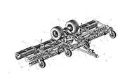
- Trained as a disc harrow agricultural device has the central frame 1 with the drawbar 2. At the central frame 1 are by means of joints 3, the two side sections 4 and 5 in the direction of travel 6 extending pivot axes 7 from the in Fig.1 shown employment position in the Fig.2 shown transport position pivotally arranged.
- the side sections 4 and 5 have the support frames 8 and 9.
- the hydraulic cylinder 10 for pivoting the side sections 4 and 5 from the working position according to Fig.1 in the in Fig.2 arranged transport position shown.
- the hydraulic cylinders 10 are connected by means not shown hydraulic lines with a hydraulic system, such as a tractor designed as a harrow tillage tractor pulling tractor.
- roller elements 15 are arranged with corresponding support arms in height adjustable manner relative to the discs 14 for compressing the loosened by the discs 14 soil in a known and therefore not shown in detail and explanatory manner.
- chassis 16 At the rear end of the central frame 1 which is pivotable by means of at least one hydraulic cylinder chassis 16 is arranged.
- the chassis 16 In the in Fig.1 illustrated working position of the harrow, the chassis 16 is excavated and located above the central frame 1 in a pivoted manner.
- This chassis 16 can be when the disc harrow in transport position according to Fig.2 is moved back to a position so that the tools 14 and 15 of the harrow can be lifted off the ground and the device can be transported by the chassis 16 accordingly.
- the traction coupling 10 On the front of the drawbar 2 is the traction coupling 10, with which the device is to be coupled to a traction device of a tractors, not shown.
- the in transport position according to Fig.2 brought disc harrow can be parked in their parking position on Abstell gan 18, as in Fig.2 and 4 is shown.
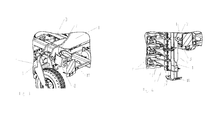
- Abstell gan 18 which are in the working position of the device in the central frame 1 or the drawbar 2 arranged storage brackets 19 are carried with the device, taken from this storage position 19 and located at the lower ends of the carrier beam located in the transport position 11 of the side sections 4, 5th arranged by means not shown quick couplings in a detachable manner. If in the Abstell Sen 18 at the lower ends of the located in transport position support beams 11 are arranged, the device, as in Fig.2 and 4 shown parked on the Abstell gan 18.
Landscapes
- Life Sciences & Earth Sciences (AREA)
- Engineering & Computer Science (AREA)
- Mechanical Engineering (AREA)
- Soil Sciences (AREA)
- Environmental Sciences (AREA)
- Agricultural Machines (AREA)
Abstract
Description
- Die Erfindung betrifft ein landwirtschaftliches Gerät gemäß des Oberbegriffes des Patentanspruches 1.
- Ein derartiges landwirtschaftliches Gerät ist in der
DE 10 2004 031 818 A1 beschrieben. Dieses landwirtschaftliche Gerät ist als gezogenes Bodenbearbeitungsgerät ausgebildet. Dieses Bodenbearbeitungsgerät weist einen Tragrahmen auf, an den um in Fahrtrichtung weisende Gelenkachsen aus einer etwa horizontalen Arbeitsstellung in eine etwa vertikale Transportstellung verschwenkbare Trägerbalken der Seitensektionen angeordnet sind. An den Trägerbalken sind Bearbeitungselemente angeordnet. Wenn die an dem Tragrahmen angeordneten Trägerbalken der Seitensektionen sich in vertikaler Ausrichtung in Transportstellung befinden, weisen die inneren Enden der Trägerbalken in dieser Stellung in Richtung der Bodenoberfläche. Wenn das Gerät mit den sich in Transportstellung befindlichen Trägerbalken der Seitensektionen nach Beendigung des Arbeitseinsatzes abgestellt werden soll, wird das Gerät im vorderen Bereich auf zumindest einer Abstellstützen zum Abstellen der Maschine, wenn die Trägerbalken sich in Transportstellung befinden, abgestellt. Die Abstellstützen sind hier an der Zugdeichsel des Gerätes angeordnet. Hierzu wird eine relativ aufwändig ausgestaltete Abstellstütze verwendet. Außerdem muss an der Zugdeichsel eine entsprechende Anordnung vorgesehen werden, an der die Abstellstütze in entsprechender Weise in abnehmbarer und/oder verstellbarer Weise befestigt ist. Die bekannten Abstellstützen sind darüber hinaus teleskopierbar ausgebildet und damit relativ teuer. - Der Erfindung liegt die Aufgabe zu Grunde, eine vereinfachte Anordnung und Ausgestaltung der Abstellstützen zum Abstellen des Gerätes zu schaffen.
- Diese Aufgabe wird erfindungsgemäß dadurch gelöst, dass zumindest eine Abstellstütze an dem unteren Ende eines sich in Transportstellung befindlichen Trägerbalkens anordbar ist.
- Infolge dieser Maßnahme kann das in Transportstellung eingeklappte Gerät sicher abgestellt werden. Das Gerät kann jeweils einfach auf den an dem sich in Transportstellung befindlichen Trägerbalken angeordneten Stützfuß der Abstellstützen abgestellt werden. Weiterhin ist die Bewegung der Deichsel nicht behindert. Somit kann das Gerät problemlos an dem das Gerät ziehenden Schlepper angekoppelt und abgekoppelt werden. Somit werden die sich bereits in Bodennähe befindlichen Enden der sich in Transportstellung befindlichen Tragbalken in Verbindung mit den daran anzuordnenden und/oder angeordneten Abstellstützen zum sicheren Abstellen des Gerätes in Abstellposition benutzt. Darüber hinaus wird aufgrund der sich gegenüber den Tragbalken zur Maschinenmitte hin versetzt angeordneten Gelenken, um welche die Trägerbalken der Seitensektionen von Arbeitsstellung in Transportstellung verschwenkbar sind, gewährleistet, dass das so abgestellte Gerät gegen ein ungewolltes Aufklappen der Trägerbalken der Seitensektionen, aufgrund nachlassender Hydraulikzylinder zusätzlich ohne weitere Maßnahmen automatisch gesichert ist.
- Um die Abstellstützen schnell und einfach an den Trägerbalken anzuordnen oder auch wieder abnehmen zu können, ist vorgesehen, dass die an dem unteren Ende des sich in Transportstellung befindlichen Trägerbalkens anzuordnende Abstellstütze mittels einer Schnellkupplung in abnehmbarer Weise angeordnet ist.
- Um die Abstellstützen in Arbeitsstellung der Trägerbalken einfach mit dem Gerät mitführen zu können, ist vorgesehen, dass an dem Tragrahmen eine Halterung angeordnet ist, an welcher die Abstellstütze bei sich in Arbeitsstellung befindlichen Trägerbalken befestigbar ist.
- Weitere Einzelheiten der Erfindung sind der Beispielsbeschreibung zu entnehmen. Die Zeichnungen zeigen
- Fig.1
- das als Scheibenegge ausgebildete landwirtschaftliche Gerät in Arbeitsstellung und in perspektivischer Ansicht,
- Fig.2
- das als Scheibenegge ausgebildete landwirtschaftliches Gerät in Transportstellung und in perspektivischer Ansicht,
- Fig.3
- die Anordnung einer der Abstellstützen bei sich in Arbeitsstellung befindlichen Gerät am Rahmen des Gerätes in einer Aufbewahrungsposition in perspektivischer Ansicht, in Teilansicht und vergrößerter Darstellung und
- Fig.4
- die Anordnung einer der Abstellstützen bei sich in Transportstellung befindlichen Gerät an dem Boden zugewandten Ende eines Trägerbalkens einer Seitensektion in perspektivischer Ansicht, in Teilansicht und vergrößerter Darstellung.
- Das als Scheibenegge ausgebildete landwirtschaftliche Gerät weist den Zentralrahmen 1 mit der Zugdeichsel 2 auf. An dem Zentralrahmen 1 sind mittels Gelenken 3 die beiden Seitensektionen 4 und 5 um in Fahrtrichtung 6 verlaufende Schwenkachsen 7 aus der in
Fig.1 dargestellten Arbeitsstellung in die inFig.2 dargestellte Transportstellung schwenkbar angeordnet. Die Seitensektionen 4 und 5 weisen die Tragrahmen 8 und 9 auf. Zwischen dem Tragrahmen 8 und 9 einerseits und dem Zentralrahmen 1 andererseits die Hydraulikzylinder 10 zum Verschwenken der Seitensektionen 4 und 5 aus der Arbeitsposition gemäßFig.1 in die inFig.2 dargestellte Transportposition angeordnet. Die Hydraulikzylinder 10 sind mittels nicht dargestellter Hydraulikleitungen mit einer Hydraulikanlage, beispielsweise eines als Scheibenegge ausgebildete Bodenbearbeitungsgerätes ziehenden Ackerschlepper verbunden. An dem Tragrahmen 8 und 9 sind zwei hintereinander und zumindest annähernd parallel zueinander angeordnete quer zur Bewegungsrichtung 6 der Scheibenegge verlaufende und vorzugsweise zueinander verschiebbare Trägerbalken 11 angeordnet. An jedem Trägerbalken 11 ist eine Vielzahl von Armen 12 mittels einer sogenannten Gummilagerung federnd gelagert angeordnet. Somit ist eine elastische Anordnung und Lagerung 12 der Arme 13 an den Trägerbalken 11 geschaffen. An dem der Gummilagerung 12 entgegengesetzten Enden der Arme 13 sind schräg zur Fahrtrichtung 6 angestellte Scheiben zur Bodenbearbeitung in bekannter und 3 nicht näher dargestellter Weise frei drehbar gelagert. Die Scheiben 14 in der vorderen Querreihe sind entgegengesetzt schräg zu den Scheiben 14 in der hinteren Querreihe angestellt. - Hinter den als den Boden lockernden Bodenbearbeitungswerkzeugen ausgebildeten Scheiben 14 sind die Walzenelemente 15 mit entsprechenden Tragarmen in höhenverstellbarer Weise gegenüber den Scheiben 14 zum Verdichten des von den Scheiben 14 gelockerten Bodens in bekannter und daher nicht näher dargestellter und erläuternder Weise angeordnet.
- Am hinteren Ende des Zentralrahmens 1 ist das mittels zumindest eines Hydraulikzylinders verschwenkbare Fahrwerk 16 angeordnet. In der in
Fig.1 dargestellten Arbeitsstellung des Bodenbearbeitungsgerätes ist das Fahrwerk 16 ausgehoben und befindet sich oberhalb des Zentralrahmens 1 in verschwenkter Weise. Dieses Fahrwerk 16 lässt sich, wenn die Scheibenegge in Transportstellung gemäßFig.2 gebracht wird, in eine Position nach hinten schwenken, so dass die Werkzeuge 14 und 15 des Bodenbearbeitungsgerätes vom Boden abgehoben werden und das Gerät mittels des Fahrwerks 16 entsprechend transportiert werden kann. Auf der Vorderseite der Zugdeichsel 2 befindet sich die Zugkupplung 10, mit welcher das Gerät an eine Zugvorrichtung eines nicht gezeigten Ackerschleppers anzukuppeln ist. - Die in Transportstellung gemäß
Fig.2 gebrachte Scheibenegge lässt sich in ihrer Abstellposition auf Abstellstützen 18 abstellen, wie inFig.2 und4 gezeigt ist. Hierzu werden die Abstellstützen 18, die in Arbeitsstellung des Gerätes in am Zentralrahmen 1 oder der Zugdeichsel 2 angeordneten Aufbewahrungshalterungen 19 mit dem Gerät mitgeführt werden, aus diesem Aufbewahrungshaltung 19 entnommen und an den unteren Enden der sich in Transportstellung befindlichen Trägerbalken 11 der Seitensektionen 4, 5 mittels nicht näher dargestellter Schnellkupplungen in abnehmbar Weise angeordnet. Wenn in die Abstellstützen 18 an den unteren Enden der sich in Transportstellung befindlichen Trägerbalken 11 angeordnet sind, kann das Gerät, wie inFig.2 und4 gezeigt, auf den Abstellstützen 18 abgestellt werden. - Wenn das Gerät aus der in den
Fig.2 und4 dargestellte Transportstellung in die in derFig.1 dargestellten Arbeitsstellung verbracht werden soll, werden vor dem Verschwenken der Seitensektionen 4, 5 aus der Transportstellung in die Arbeitsstellung die Abstellstützen 18 von den unteren Enden der Trägerbalken 11 abgenommen und in die Aufbewahrungshalterung 19 verbracht.
Claims (3)
- Landwirtschaftliches Gerät, insbesondere Bodenbearbeitungsgerät, mit einem Tragrahmen (1) an den um in Fahrtrichtung weisende Gelenkachsen (6) aus einer etwa horizontalen Arbeitsstellung (Fig.1) in eine etwa vertikale Transportstellung (Fig.2) verschwenkbare Trägerbalken (11) ausgebildete Seitensektionen (4, 5) angeordnet sind, wobei an den Trägerbalken (11) Bearbeitungselemente (14, angeordnet sind, wobei Abstellstützen (18) zum Abstellen der Maschine, wenn die Trägerbalken (11) sich in Transportstellung befinden, vorgesehen sind, dadurch gekennzeichnet, dass zumindest eine Abstellstütze (18) an dem unteren Ende eines sich in Transportstellung befindlichen Trägerbalkens (11) anordbar ist.
- Landwirtschaftliches Gerät nach Anspruch 1, dadurch gekennzeichnet, dass die an dem unteren Ende des sich in Transportstellung befindlichen Trägerbalken (11) anzuordnende Abstellstütze (18) mittels einer Schnellkupplung in abnehmbar Weise angeordnet ist.
- Landwirtschaftliches Gerät nach einem der vorstehenden Ansprüche, dadurch gekennzeichnet, dass an dem Tragrahmen (1) eine Halterung (19) angeordnet ist, an welcher die Abstellstütze (18) bei sich in Arbeitsstellung befindlichen Trägerbalken (11) befestigbar ist.
Applications Claiming Priority (1)
| Application Number | Priority Date | Filing Date | Title |
|---|---|---|---|
| DE102014109502.2A DE102014109502A1 (de) | 2014-07-08 | 2014-07-08 | Landwirtschaftliches Gerät |
Publications (2)
| Publication Number | Publication Date |
|---|---|
| EP2965605A1 true EP2965605A1 (de) | 2016-01-13 |
| EP2965605B1 EP2965605B1 (de) | 2017-03-08 |
Family
ID=53716425
Family Applications (1)
| Application Number | Title | Priority Date | Filing Date |
|---|---|---|---|
| EP15401064.9A Active EP2965605B1 (de) | 2014-07-08 | 2015-07-06 | Landwirtschaftliches gerät |
Country Status (2)
| Country | Link |
|---|---|
| EP (1) | EP2965605B1 (de) |
| DE (1) | DE102014109502A1 (de) |
Cited By (1)
| Publication number | Priority date | Publication date | Assignee | Title |
|---|---|---|---|---|
| DE102022105183A1 (de) | 2022-03-04 | 2023-09-07 | Horsch Maschinen Gmbh | Landwirtschaftliche arbeitsmaschine mit zusatzfahrwerk und verfahren zur einstellung einer achslast |
Citations (2)
| Publication number | Priority date | Publication date | Assignee | Title |
|---|---|---|---|---|
| DE102004031818A1 (de) | 2004-07-01 | 2006-01-26 | Amazonen-Werke H. Dreyer Gmbh & Co. Kg | Scheibengerät |
| DE102006047890A1 (de) * | 2006-10-10 | 2008-04-17 | Lemken Gmbh & Co. Kg | Bodenbearbeitungsgerät mit großer Arbeitsbreite |
-
2014
- 2014-07-08 DE DE102014109502.2A patent/DE102014109502A1/de not_active Withdrawn
-
2015
- 2015-07-06 EP EP15401064.9A patent/EP2965605B1/de active Active
Patent Citations (2)
| Publication number | Priority date | Publication date | Assignee | Title |
|---|---|---|---|---|
| DE102004031818A1 (de) | 2004-07-01 | 2006-01-26 | Amazonen-Werke H. Dreyer Gmbh & Co. Kg | Scheibengerät |
| DE102006047890A1 (de) * | 2006-10-10 | 2008-04-17 | Lemken Gmbh & Co. Kg | Bodenbearbeitungsgerät mit großer Arbeitsbreite |
Cited By (1)
| Publication number | Priority date | Publication date | Assignee | Title |
|---|---|---|---|---|
| DE102022105183A1 (de) | 2022-03-04 | 2023-09-07 | Horsch Maschinen Gmbh | Landwirtschaftliche arbeitsmaschine mit zusatzfahrwerk und verfahren zur einstellung einer achslast |
Also Published As
| Publication number | Publication date |
|---|---|
| EP2965605B1 (de) | 2017-03-08 |
| DE102014109502A1 (de) | 2016-01-14 |
Similar Documents
| Publication | Publication Date | Title |
|---|---|---|
| EP3122168B1 (de) | Bodenbearbeitungsgerät mit striegel- oder einebnungsvorrichtung | |
| DE1915825A1 (de) | Bodenbearbeitungsgeraet | |
| DE102011122537B4 (de) | Integriertes Bodenbearbeitungsgerät für Drehpflüge | |
| DE3105639A1 (de) | "geraetekombination fuer die landwirtschaft" | |
| EP2854495B1 (de) | Landwirtschaftliches bodenbearbeitungsgeraet | |
| EP2965599A1 (de) | Bodenbearbeitungsvorrichtung | |
| EP2232974B1 (de) | Ein an das Kupplungselement eines Ackerschleppers ankuppelbares landwirschaftliches Gerät | |
| EP2965605B1 (de) | Landwirtschaftliches gerät | |
| EP2944170B1 (de) | Landwirtschaftliche verteilmaschine, insbesondere sämaschine, und verfahren zur höhenverstellung von säscharen | |
| EP2840880B1 (de) | Gezogenes landwirtschaftliches gerät | |
| EP3085219B1 (de) | Landwirtschaftliches gerät | |
| DE102005030923A1 (de) | Landwirtschaftsmaschine in Form einer Scheibenegge | |
| DE102008021539A1 (de) | Grubber | |
| DE6939693U (de) | Geraeterahmen, insbesondere fuer bodenbearbeitungsgeraete | |
| EP1529427B1 (de) | Landwirtschaftliches Bodenbearbeitungsgerät und/oder Bestellgerät | |
| DE1457719A1 (de) | Scheibenegge mit einem Tragrahmen und einem vom Tragrahmen gehaltenen Scheibensatz sowie mit Bodenraedern | |
| DE2322848C2 (de) | Frontlader für Ackerschlepper od.dgl | |
| EP3000295B1 (de) | Gezogenes landwirtschaftliches gerät | |
| EP2656709A1 (de) | Bodenbearbeitungsgerät mit zwei durch eine Schnellkupplung verbindbaren Bodenbearbeitungsvorrichtungen | |
| DE4306599A1 (de) | Aufgesatteltes Bodenbearbeitungsgerät | |
| DE102014110100A1 (de) | Drehpflug | |
| DE102006047890A1 (de) | Bodenbearbeitungsgerät mit großer Arbeitsbreite | |
| AT14314U1 (de) | Hebeeinrichtung | |
| DE19858985A1 (de) | Boden-Bearbeitungsgerät | |
| DE4139229A1 (de) | Schwenkpflug |
Legal Events
| Date | Code | Title | Description |
|---|---|---|---|
| PUAI | Public reference made under article 153(3) epc to a published international application that has entered the european phase |
Free format text: ORIGINAL CODE: 0009012 |
|
| AK | Designated contracting states |
Kind code of ref document: A1 Designated state(s): AL AT BE BG CH CY CZ DE DK EE ES FI FR GB GR HR HU IE IS IT LI LT LU LV MC MK MT NL NO PL PT RO RS SE SI SK SM TR |
|
| AX | Request for extension of the european patent |
Extension state: BA ME |
|
| 17P | Request for examination filed |
Effective date: 20160704 |
|
| RBV | Designated contracting states (corrected) |
Designated state(s): AL AT BE BG CH CY CZ DE DK EE ES FI FR GB GR HR HU IE IS IT LI LT LU LV MC MK MT NL NO PL PT RO RS SE SI SK SM TR |
|
| GRAP | Despatch of communication of intention to grant a patent |
Free format text: ORIGINAL CODE: EPIDOSNIGR1 |
|
| RIC1 | Information provided on ipc code assigned before grant |
Ipc: A01B 73/04 20060101AFI20161123BHEP |
|
| INTG | Intention to grant announced |
Effective date: 20161214 |
|
| GRAS | Grant fee paid |
Free format text: ORIGINAL CODE: EPIDOSNIGR3 |
|
| GRAA | (expected) grant |
Free format text: ORIGINAL CODE: 0009210 |
|
| RIN1 | Information on inventor provided before grant (corrected) |
Inventor name: ANDRICH, ROBERT |
|
| AK | Designated contracting states |
Kind code of ref document: B1 Designated state(s): AL AT BE BG CH CY CZ DE DK EE ES FI FR GB GR HR HU IE IS IT LI LT LU LV MC MK MT NL NO PL PT RO RS SE SI SK SM TR |
|
| REG | Reference to a national code |
Ref country code: GB Ref legal event code: FG4D Free format text: NOT ENGLISH |
|
| REG | Reference to a national code |
Ref country code: CH Ref legal event code: EP Ref country code: AT Ref legal event code: REF Ref document number: 872683 Country of ref document: AT Kind code of ref document: T Effective date: 20170315 |
|
| REG | Reference to a national code |
Ref country code: IE Ref legal event code: FG4D Free format text: LANGUAGE OF EP DOCUMENT: GERMAN |
|
| REG | Reference to a national code |
Ref country code: DE Ref legal event code: R096 Ref document number: 502015000686 Country of ref document: DE |
|
| REG | Reference to a national code |
Ref country code: FR Ref legal event code: PLFP Year of fee payment: 3 |
|
| REG | Reference to a national code |
Ref country code: LT Ref legal event code: MG4D |
|
| REG | Reference to a national code |
Ref country code: NL Ref legal event code: MP Effective date: 20170308 |
|
| PG25 | Lapsed in a contracting state [announced via postgrant information from national office to epo] |
Ref country code: HR Free format text: LAPSE BECAUSE OF FAILURE TO SUBMIT A TRANSLATION OF THE DESCRIPTION OR TO PAY THE FEE WITHIN THE PRESCRIBED TIME-LIMIT Effective date: 20170308 Ref country code: NO Free format text: LAPSE BECAUSE OF FAILURE TO SUBMIT A TRANSLATION OF THE DESCRIPTION OR TO PAY THE FEE WITHIN THE PRESCRIBED TIME-LIMIT Effective date: 20170608 Ref country code: GR Free format text: LAPSE BECAUSE OF FAILURE TO SUBMIT A TRANSLATION OF THE DESCRIPTION OR TO PAY THE FEE WITHIN THE PRESCRIBED TIME-LIMIT Effective date: 20170609 Ref country code: FI Free format text: LAPSE BECAUSE OF FAILURE TO SUBMIT A TRANSLATION OF THE DESCRIPTION OR TO PAY THE FEE WITHIN THE PRESCRIBED TIME-LIMIT Effective date: 20170308 Ref country code: LT Free format text: LAPSE BECAUSE OF FAILURE TO SUBMIT A TRANSLATION OF THE DESCRIPTION OR TO PAY THE FEE WITHIN THE PRESCRIBED TIME-LIMIT Effective date: 20170308 |
|
| PG25 | Lapsed in a contracting state [announced via postgrant information from national office to epo] |
Ref country code: RS Free format text: LAPSE BECAUSE OF FAILURE TO SUBMIT A TRANSLATION OF THE DESCRIPTION OR TO PAY THE FEE WITHIN THE PRESCRIBED TIME-LIMIT Effective date: 20170308 Ref country code: ES Free format text: LAPSE BECAUSE OF FAILURE TO SUBMIT A TRANSLATION OF THE DESCRIPTION OR TO PAY THE FEE WITHIN THE PRESCRIBED TIME-LIMIT Effective date: 20170308 Ref country code: LV Free format text: LAPSE BECAUSE OF FAILURE TO SUBMIT A TRANSLATION OF THE DESCRIPTION OR TO PAY THE FEE WITHIN THE PRESCRIBED TIME-LIMIT Effective date: 20170308 Ref country code: SE Free format text: LAPSE BECAUSE OF FAILURE TO SUBMIT A TRANSLATION OF THE DESCRIPTION OR TO PAY THE FEE WITHIN THE PRESCRIBED TIME-LIMIT Effective date: 20170308 Ref country code: BG Free format text: LAPSE BECAUSE OF FAILURE TO SUBMIT A TRANSLATION OF THE DESCRIPTION OR TO PAY THE FEE WITHIN THE PRESCRIBED TIME-LIMIT Effective date: 20170608 |
|
| PG25 | Lapsed in a contracting state [announced via postgrant information from national office to epo] |
Ref country code: NL Free format text: LAPSE BECAUSE OF FAILURE TO SUBMIT A TRANSLATION OF THE DESCRIPTION OR TO PAY THE FEE WITHIN THE PRESCRIBED TIME-LIMIT Effective date: 20170308 |
|
| PG25 | Lapsed in a contracting state [announced via postgrant information from national office to epo] |
Ref country code: SK Free format text: LAPSE BECAUSE OF FAILURE TO SUBMIT A TRANSLATION OF THE DESCRIPTION OR TO PAY THE FEE WITHIN THE PRESCRIBED TIME-LIMIT Effective date: 20170308 Ref country code: RO Free format text: LAPSE BECAUSE OF FAILURE TO SUBMIT A TRANSLATION OF THE DESCRIPTION OR TO PAY THE FEE WITHIN THE PRESCRIBED TIME-LIMIT Effective date: 20170308 Ref country code: IT Free format text: LAPSE BECAUSE OF FAILURE TO SUBMIT A TRANSLATION OF THE DESCRIPTION OR TO PAY THE FEE WITHIN THE PRESCRIBED TIME-LIMIT Effective date: 20170308 Ref country code: EE Free format text: LAPSE BECAUSE OF FAILURE TO SUBMIT A TRANSLATION OF THE DESCRIPTION OR TO PAY THE FEE WITHIN THE PRESCRIBED TIME-LIMIT Effective date: 20170308 Ref country code: CZ Free format text: LAPSE BECAUSE OF FAILURE TO SUBMIT A TRANSLATION OF THE DESCRIPTION OR TO PAY THE FEE WITHIN THE PRESCRIBED TIME-LIMIT Effective date: 20170308 |
|
| PG25 | Lapsed in a contracting state [announced via postgrant information from national office to epo] |
Ref country code: SM Free format text: LAPSE BECAUSE OF FAILURE TO SUBMIT A TRANSLATION OF THE DESCRIPTION OR TO PAY THE FEE WITHIN THE PRESCRIBED TIME-LIMIT Effective date: 20170308 Ref country code: IS Free format text: LAPSE BECAUSE OF FAILURE TO SUBMIT A TRANSLATION OF THE DESCRIPTION OR TO PAY THE FEE WITHIN THE PRESCRIBED TIME-LIMIT Effective date: 20170708 Ref country code: PL Free format text: LAPSE BECAUSE OF FAILURE TO SUBMIT A TRANSLATION OF THE DESCRIPTION OR TO PAY THE FEE WITHIN THE PRESCRIBED TIME-LIMIT Effective date: 20170308 Ref country code: PT Free format text: LAPSE BECAUSE OF FAILURE TO SUBMIT A TRANSLATION OF THE DESCRIPTION OR TO PAY THE FEE WITHIN THE PRESCRIBED TIME-LIMIT Effective date: 20170710 |
|
| REG | Reference to a national code |
Ref country code: DE Ref legal event code: R097 Ref document number: 502015000686 Country of ref document: DE |
|
| PLBE | No opposition filed within time limit |
Free format text: ORIGINAL CODE: 0009261 |
|
| STAA | Information on the status of an ep patent application or granted ep patent |
Free format text: STATUS: NO OPPOSITION FILED WITHIN TIME LIMIT |
|
| PG25 | Lapsed in a contracting state [announced via postgrant information from national office to epo] |
Ref country code: DK Free format text: LAPSE BECAUSE OF FAILURE TO SUBMIT A TRANSLATION OF THE DESCRIPTION OR TO PAY THE FEE WITHIN THE PRESCRIBED TIME-LIMIT Effective date: 20170308 |
|
| 26N | No opposition filed |
Effective date: 20171211 |
|
| PG25 | Lapsed in a contracting state [announced via postgrant information from national office to epo] |
Ref country code: SI Free format text: LAPSE BECAUSE OF FAILURE TO SUBMIT A TRANSLATION OF THE DESCRIPTION OR TO PAY THE FEE WITHIN THE PRESCRIBED TIME-LIMIT Effective date: 20170308 |
|
| REG | Reference to a national code |
Ref country code: IE Ref legal event code: MM4A |
|
| PG25 | Lapsed in a contracting state [announced via postgrant information from national office to epo] |
Ref country code: IE Free format text: LAPSE BECAUSE OF NON-PAYMENT OF DUE FEES Effective date: 20170706 |
|
| REG | Reference to a national code |
Ref country code: BE Ref legal event code: MM Effective date: 20170731 |
|
| REG | Reference to a national code |
Ref country code: FR Ref legal event code: PLFP Year of fee payment: 4 |
|
| PG25 | Lapsed in a contracting state [announced via postgrant information from national office to epo] |
Ref country code: LU Free format text: LAPSE BECAUSE OF NON-PAYMENT OF DUE FEES Effective date: 20170706 |
|
| PG25 | Lapsed in a contracting state [announced via postgrant information from national office to epo] |
Ref country code: BE Free format text: LAPSE BECAUSE OF NON-PAYMENT OF DUE FEES Effective date: 20170731 |
|
| PG25 | Lapsed in a contracting state [announced via postgrant information from national office to epo] |
Ref country code: MT Free format text: LAPSE BECAUSE OF FAILURE TO SUBMIT A TRANSLATION OF THE DESCRIPTION OR TO PAY THE FEE WITHIN THE PRESCRIBED TIME-LIMIT Effective date: 20170308 |
|
| REG | Reference to a national code |
Ref country code: CH Ref legal event code: PL |
|
| PG25 | Lapsed in a contracting state [announced via postgrant information from national office to epo] |
Ref country code: LI Free format text: LAPSE BECAUSE OF NON-PAYMENT OF DUE FEES Effective date: 20180731 Ref country code: CH Free format text: LAPSE BECAUSE OF NON-PAYMENT OF DUE FEES Effective date: 20180731 |
|
| PG25 | Lapsed in a contracting state [announced via postgrant information from national office to epo] |
Ref country code: MC Free format text: LAPSE BECAUSE OF FAILURE TO SUBMIT A TRANSLATION OF THE DESCRIPTION OR TO PAY THE FEE WITHIN THE PRESCRIBED TIME-LIMIT Effective date: 20170308 Ref country code: HU Free format text: LAPSE BECAUSE OF FAILURE TO SUBMIT A TRANSLATION OF THE DESCRIPTION OR TO PAY THE FEE WITHIN THE PRESCRIBED TIME-LIMIT; INVALID AB INITIO Effective date: 20150706 |
|
| PG25 | Lapsed in a contracting state [announced via postgrant information from national office to epo] |
Ref country code: CY Free format text: LAPSE BECAUSE OF FAILURE TO SUBMIT A TRANSLATION OF THE DESCRIPTION OR TO PAY THE FEE WITHIN THE PRESCRIBED TIME-LIMIT Effective date: 20170308 |
|
| PG25 | Lapsed in a contracting state [announced via postgrant information from national office to epo] |
Ref country code: MK Free format text: LAPSE BECAUSE OF FAILURE TO SUBMIT A TRANSLATION OF THE DESCRIPTION OR TO PAY THE FEE WITHIN THE PRESCRIBED TIME-LIMIT Effective date: 20170308 |
|
| GBPC | Gb: european patent ceased through non-payment of renewal fee |
Effective date: 20190706 |
|
| PG25 | Lapsed in a contracting state [announced via postgrant information from national office to epo] |
Ref country code: TR Free format text: LAPSE BECAUSE OF FAILURE TO SUBMIT A TRANSLATION OF THE DESCRIPTION OR TO PAY THE FEE WITHIN THE PRESCRIBED TIME-LIMIT Effective date: 20170308 |
|
| PG25 | Lapsed in a contracting state [announced via postgrant information from national office to epo] |
Ref country code: GB Free format text: LAPSE BECAUSE OF NON-PAYMENT OF DUE FEES Effective date: 20190706 |
|
| PG25 | Lapsed in a contracting state [announced via postgrant information from national office to epo] |
Ref country code: AL Free format text: LAPSE BECAUSE OF FAILURE TO SUBMIT A TRANSLATION OF THE DESCRIPTION OR TO PAY THE FEE WITHIN THE PRESCRIBED TIME-LIMIT Effective date: 20170308 |
|
| REG | Reference to a national code |
Ref country code: DE Ref legal event code: R081 Ref document number: 502015000686 Country of ref document: DE Owner name: AMAZONEN-WERKE H. DREYER SE & CO. KG, DE Free format text: FORMER OWNER: AMAZONEN-WERKE H. DREYER GMBH & CO. KG, 49205 HASBERGEN, DE |
|
| REG | Reference to a national code |
Ref country code: AT Ref legal event code: MM01 Ref document number: 872683 Country of ref document: AT Kind code of ref document: T Effective date: 20200706 |
|
| PG25 | Lapsed in a contracting state [announced via postgrant information from national office to epo] |
Ref country code: AT Free format text: LAPSE BECAUSE OF NON-PAYMENT OF DUE FEES Effective date: 20200706 |
|
| P01 | Opt-out of the competence of the unified patent court (upc) registered |
Effective date: 20230523 |
|
| PGFP | Annual fee paid to national office [announced via postgrant information from national office to epo] |
Ref country code: FR Payment date: 20250610 Year of fee payment: 11 |
|
| PGFP | Annual fee paid to national office [announced via postgrant information from national office to epo] |
Ref country code: DE Payment date: 20250604 Year of fee payment: 11 |