EP2965660B1 - Sitzmöbel - Google Patents
Sitzmöbel Download PDFInfo
- Publication number
- EP2965660B1 EP2965660B1 EP15176150.9A EP15176150A EP2965660B1 EP 2965660 B1 EP2965660 B1 EP 2965660B1 EP 15176150 A EP15176150 A EP 15176150A EP 2965660 B1 EP2965660 B1 EP 2965660B1
- Authority
- EP
- European Patent Office
- Prior art keywords
- furniture
- piece
- socket
- energy store
- energy storage
- Prior art date
- Legal status (The legal status is an assumption and is not a legal conclusion. Google has not performed a legal analysis and makes no representation as to the accuracy of the status listed.)
- Active
Links
Images

Classifications
-
- A—HUMAN NECESSITIES
- A47—FURNITURE; DOMESTIC ARTICLES OR APPLIANCES; COFFEE MILLS; SPICE MILLS; SUCTION CLEANERS IN GENERAL
- A47C—CHAIRS; SOFAS; BEDS
- A47C1/00—Chairs adapted for special purposes
- A47C1/02—Reclining or easy chairs
- A47C1/022—Reclining or easy chairs having independently-adjustable supporting parts
- A47C1/024—Reclining or easy chairs having independently-adjustable supporting parts the parts, being the back-rest, or the back-rest and seat unit, having adjustable inclination
- A47C1/0242—Reclining or easy chairs having independently-adjustable supporting parts the parts, being the back-rest, or the back-rest and seat unit, having adjustable inclination by electric motors
-
- A—HUMAN NECESSITIES
- A47—FURNITURE; DOMESTIC ARTICLES OR APPLIANCES; COFFEE MILLS; SPICE MILLS; SUCTION CLEANERS IN GENERAL
- A47C—CHAIRS; SOFAS; BEDS
- A47C7/00—Parts, details, or accessories of chairs or stools
- A47C7/50—Supports for the feet or the legs
- A47C7/506—Supports for the feet or the legs of adjustable type
-
- A—HUMAN NECESSITIES
- A47—FURNITURE; DOMESTIC ARTICLES OR APPLIANCES; COFFEE MILLS; SPICE MILLS; SUCTION CLEANERS IN GENERAL
- A47C—CHAIRS; SOFAS; BEDS
- A47C7/00—Parts, details, or accessories of chairs or stools
- A47C7/62—Accessories for chairs
- A47C7/72—Adaptations for incorporating lamps, radio sets, bars, telephones, ventilation, heating or cooling arrangements or the like
- A47C7/74—Adaptations for incorporating lamps, radio sets, bars, telephones, ventilation, heating or cooling arrangements or the like for ventilation, heating or cooling
- A47C7/748—Adaptations for incorporating lamps, radio sets, bars, telephones, ventilation, heating or cooling arrangements or the like for ventilation, heating or cooling for heating
Definitions
- the present invention relates to a sitting or lying furniture with at least one electrically operable or operated unit.
- the furniture may be, for example, a chair, in particular a padded seat, e.g. TV armchair or massage chair, act.
- Such furniture is generally known (eg. DE102010002833 A1 or US7735931 B1 ).
- an electric drive can be provided by means of which, for example, a backrest of the furniture can be adjusted.
- Power is always supplied by a cable that connects the furniture to the public power grid.
- the cable restricts the mobility of the furniture. So the furniture must always be placed near a power outlet. Also, the cable can be a hindrance to a change of location of the furniture. Furthermore, the cable may pose a risk of tripping. Last but not least, a cable that extends from a piece of furniture to a socket is visually less appealing.
- the sitting or lying furniture is directly connectable to and / or connected to an energy store, in particular accumulator, which forms an energy source for the unit.
- the energy store can preferably be attached directly to the furniture.
- the sitting or lying furniture can be powered independently of the public power grid with electrical energy.
- the furniture is particularly self-sufficient with power. Disturbing cables are therefore not provided.
- the energy store may preferably be rechargeable.
- a rechargeable battery can be used, for example, as lithium-ion rechargeable battery, lithium-cobalt dioxide rechargeable battery, lithium-polymer rechargeable battery, lithium-manganese rechargeable battery, lithium-iron-phosphate rechargeable battery, lithium-iron-yttrium-phosphate rechargeable battery, lithium-air rechargeable battery.
- Rechargeable battery lithium titanate rechargeable battery, lithium sulfur rechargeable battery, lithium metal polymer rechargeable battery, sodium nickel chloride rechargeable battery, sodium sulfur rechargeable battery, nickel cadmium rechargeable battery, nickel iron rechargeable battery, nickel hydrogen Accumulator, nickel-metal hydride accumulator, nickel-zinc accumulator, lead accumulator, organic polymer, alkali-manganese accumulator, tin-sulfur lithium accumulator, silver-zinc accumulator, vanadium redox accumulator, zinc-bromine accumulator and / or silicon-air accumulator.
- the energy storage device can also be designed as a primary cell, in particular as an alkali-manganese battery, zinc chloride battery or zinc-carbon battery.
- special batteries are conceivable, for example a zinc air battery, mercury oxide zinc battery, silver oxide zinc battery, nickel oxyhydroxide battery, lithium battery, lithium iron sulfide battery, aluminum air battery and / or biobattery.
- the unit is designed as an adjustable footrest, headrest, armrest, backrest, massage unit and / or heating unit.
- a piece of furniture can be moved from a sitting position to a lying position.
- the height of the furniture can be electrically adjusted.
- the footrest, the headrest, the inclination of the backrest and / or the armrests can be electrically adjusted by preferably a drive of the unit is supplied with power from the energy storage.
- an electrically operable massage unit can be provided.
- a heating unit which heats the furniture electrically.
- the furniture may comprise several different units, for example both an adjustable footrest and a heating unit.
- all electrical units of the furniture can be powered by a single energy store.
- multiple energy storage can be provided.
- the control of the electrically operable unit can be done via a control module.
- This can be integrated into the furniture, for example an armrest, integrated or designed as, in particular wireless, remote control.
- a control by means of a smartphone or tablet is conceivable.
- the energy store is releasably coupled to the seating or reclining furniture and / or coupled.
- the energy store can thus be removed in particular from the furniture, for example for loading or in the event of a defect.
- a recharged energy storage or other energy storage can then be coupled back to the furniture to to provide the unit with energy.
- the coupling allows in particular a quick and easy replacement of the energy storage.
- a coupling element may be provided on the furniture, in particular a socket.
- a plug of the energy storage can be plugged.
- a plug may be provided on the furniture as a coupling element, which e.g. can be connected to a socket of the energy storage.
- the sitting or lying furniture comprises a socket for receiving a plug of the energy store, wherein the socket has at least one at least substantially rectangular, preferably square, extending recess.
- the rectangle or square formed by the depression may in particular have rounded corners.
- two concentrically arranged recesses, in particular with parallel sides, may be provided.
- the plug can have projections which can engage in the recesses.
- the plug may have at least one at least substantially rectangular, preferably square, extending projection.
- two concentrically arranged projections, in particular with parallel sides, may be provided.
- This embodiment of the socket makes it possible to attach the energy storage in different orientations on the socket.
- a rectangular shape for example, two different orientations are possible, while in a square shape four different orientations are conceivable.
- the coupling process is greatly facilitated because it does not have to pay attention to the orientation of the energy storage.
- a further fastening element may be provided for the energy storage, whereby the energy storage in addition, especially without tools, can be secured to the furniture. Any locking, clicking, turning and / or screw connections are conceivable here.
- the charging station can have recesses corresponding to those of the socket.
- the charging station may in particular have at least one at least substantially rectangular, preferably square, extending recess.
- two concentric depressions, in particular with parallel sides, can be provided.
- the charging station may comprise a, preferably optical and / or acoustic, signal unit, for example one or more LEDs which indicate the state of charge or the charging progress.
- the energy storage can be firmly connected to the furniture or integrated into the furniture.
- such energy storage can be connected in particular via a power supply to the public power grid.
- the energy store is arranged in a rear region of the piece of furniture, in particular on the rear side of the backrest.
- the energy storage device can in principle be arranged at any point of the furniture and integrated, for example, in one of the armrests.
- the energy store can be arranged on or in a padding.
- a metal plate may be provided on the frame of the furniture, to which a socket for the energy storage can be attached.
- the energy storage only a recess for a coupling element, so for example a socket or a plug, have.
- the energy storage is located outside the cover and thus easily accessible. For visual improvement, this can be hidden, for example, in a bag.
- the panel may be adapted to the color of the cover.
- the energy store can be arranged in a recess of the padding, in particular in the backrest or one of the armrests. When energy storage is used, the energy storage can fill the recess and so close flush with the rest of the padding.
- the energy store may comprise a, preferably optical and / or acoustic, signal unit, for example one or more LEDs which indicate the state of charge.
- a signal can be emitted when the state of charge falls below a certain threshold. It is also possible to display the state of charge in the control module.
- Fig. 1 shows an example of an inventive seating furniture with a backrest 10, an armrest 12 and a footrest 14.
- an accumulator 16 is provided which forms an energy storage.
- an electrically operable unit 18, so for example the adjustable footrest 14, are supplied with power.
- FIG. 2 an energy storage 16 is shown, which can be connected to a socket 20.
- the energy store 16 has four LEDs 22, which can indicate the state of charge.
- the socket 20 can be firmly connected to a sitting or lying furniture.
- fastening means are provided, which are designed as screws 24 in the present case.
- the sleeve 20 has a diaphragm 26. This can be exchanged in particular, for example by a panel with a different color.
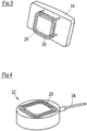
- the bush 20 has two square recesses 28. In these recesses 28, a plug 29 of the energy accumulator 16 with two square extending projections 30 engage, which in Fig. 3 is shown. Due to the square configuration of the depressions 28 or of the projections 30, the energy store 16 can be plugged into the bushing 20 at different orientations offset from one another at 90-degree angles.
- a charger 32 for an energy storage 16 is shown, which is connected via a cable 34 to the public power grid. Also the charger 32 has two square recesses 28 in order to accommodate projections 30 of an energy store 16 can.
- the sitting or lying furniture can thus be powered by an energy storage self-sufficient with electricity, so that can be dispensed with a cable that connects the furniture to the public power grid.
Landscapes
- Health & Medical Sciences (AREA)
- Dentistry (AREA)
- General Health & Medical Sciences (AREA)
- Chair Legs, Seat Parts, And Backrests (AREA)
- Charge And Discharge Circuits For Batteries Or The Like (AREA)
Description
- Die vorliegende Erfindung betrifft ein Sitz- oder Liegemöbel mit zumindest einer elektrisch betreibbaren bzw. betriebenen Einheit.
- Bei dem Möbel kann es sich beispielsweise um einen, insbesondere mit einer Polsterung versehenen, Sessel, z.B. Fernsehsessel oder Massagesessel, handeln.
- Derartige Möbel sind grundsätzlich bekannt (z. B.
DE102010002833 A1 oderUS7735931 B1 ). So kann beispielsweise ein elektrischer Antrieb vorgesehen sein, mithilfe dessen sich z.B. eine Rückenlehne des Möbels verstellen lässt. Die Stromversorgung erfolgt hierbei stets mithilfe eines Kabels, welches das Möbel mit dem öffentlichen Stromnetz verbindet. - Nachteilig daran ist, dass das Kabel die Mobilität des Möbels einschränkt. So muss das Möbel stets in der Nähe einer Steckdose platziert werden. Auch kann das Kabel bei einem Standortwechsel des Möbels hinderlich sein. Ferner kann das Kabel eine Stolpergefahr bergen. Nicht zuletzt ist ein sich von einem Möbel zu einer Steckdose erstreckendes Kabel optisch wenig ansprechend.
- Es ist eine Aufgabe der Erfindung, ein Sitz- oder Liegemöbel zu schaffen, welches kabellos mit elektrischer Energie versorgt wird.
- Die Lösung dieser Aufgabe erfolgt durch eine Vorrichtung mit den Merkmalen des Anspruchs 1.
- Erfindungsgemäß ist das Sitz- oder Liegemöbel unmittelbar mit einem Energiespeicher, insbesondere Akkumulator, verbindbar und/oder verbunden, welcher eine Energiequelle für die Einheit bildet. Der Energiespeicher kann vorzugsweise direkt am Möbel befestigt werden.
- Auf diese Weise kann das Sitz- oder Liegemöbel unabhängig vom öffentlichen Stromnetz mit elektrischer Energie versorgt werden. Das Möbel wird insbesondere autark mit Strom versorgt. Störende Kabel sind somit nicht vorgesehen.
- Der Energiespeicher kann vorzugsweise wiederaufladbar sein. Ein derartiger Akkumulator kann beispielsweise als Lithium-Ionen-Akkumulator, Lithium-Cobaltdioxid-Akkumulator, Lithium-Polymer-Akkumulator, Lithium-Mangan-Akkumulator, Lithium-Eisenphosphat-Akkumulator, Lithium-Eisen-Yttrium-Phosphat-Akkumulator, Lithium-Luft-Akkumulator, Lithium-Titanat-Akkumulator, Lithium-Schwefel-Akkumulator, Lithium-Metall-Polymer-Akkumulator, Natrium-Nickelchlorid-Akkumulator, Natrium-Schwefel-Akkumulator, Nickel-Cadmium-Akkumulator, Nickel-Eisen-Akkumulator, Nickel-Wasserstoff-Akkumulator, Nickel-Metallhydrid-Akkumulator, Nickel-Zink-Akkumulator, Bleiakkumulator, organisches Polymer, Alkali-Mangan-Akkumulator, Zinn-Schwefel-Lithium-Akkumulator, Silber-Zink-Akkumulator, Vanadium-Redox-Akkumulator, Zink-Brom-Akkumulator und/oder Silizium-Luft-Akkumulator ausgebildet sein.
- Alternativ kann der Energiespeicher auch als Primärzelle ausgebildet sein, insbesondere als Alkali-Mangan-Batterie, Zinkchlorid-Batterie oder Zink-Kohle-Batterie. Auch Spezialbatterien sind denkbar, beispielsweise eine Zink-Luft-Batterie, Quecksilberoxid-Zink-Batterie, Silberoxid-Zink-Batterie, Nickel-Oxyhydroxid-Batterie, Lithiumbatterie, Lithium-Eisensulfid-Batterie, Aluminium-Luft-Batterie und/oder Biobatterie.
- Weiterbildungen der Erfindung sind auch den abhängigen Ansprüchen, der Beschreibung sowie den beigefügten Zeichnungen zu entnehmen.
- Gemäß einer Ausführungsform ist die Einheit als verstellbare Fußstütze, Kopfstütze, Armlehne, Rückenlehne, Massageeinheit und/oder Heizeinheit ausgebildet. So kann ein Möbel beispielsweise aus einer Sitz- in eine Liegeposition verstellt werden. Auch kann z.B. die Höhe des Möbels elektrisch verstellt werden. Insbesondere können die Fußstütze, die Kopfstütze, die Neigung der Rückenlehne und/oder die Armlehnen elektrisch verstellt werden, indem vorzugsweise ein Antrieb der Einheit mit Strom aus dem Energiespeicher versorgt wird. Ferner kann eine elektrisch betreibbare Massageeinheit vorgesehen sein. Denkbar ist insbesondere auch eine Heizeinheit, welche das Möbel elektrisch heizt. Das Möbel kann mehrere verschiedene Einheiten umfassen, beispielsweise sowohl eine verstellbare Fußstütze als auch eine Heizeinheit.
- Vorzugsweise können sämtliche elektrische Einheiten des Möbels mithilfe eines einzigen Energiespeichers mit Strom versorgt werden. Alternativ können auch mehrere Energiespeicher vorgesehen sein.
- Die Steuerung der elektrisch betreibbaren Einheit kann über ein Steuermodul erfolgen. Dieses kann in das Möbel, beispielsweise eine Armlehne, integriert oder als, insbesondere drahtlose, Fernbedienung ausgebildet sein. Auch eine Steuerung mittels eines Smartphones oder Tablets ist denkbar.
- Nach einer weiteren Ausführungsform ist der Energiespeicher lösbar mit dem Sitz- oder Liegemöbel koppelbar und/oder gekoppelt. Der Energiespeicher kann somit insbesondere vom Möbel abgenommen werden, beispielsweise zum Laden oder im Falle eines Defekts. Ein erneut aufgeladener Energiespeicher bzw. ein anderer Energiespeicher kann anschließend wieder mit dem Möbel gekoppelt werden, um die Einheit mit Energie zu versorgen. Die Kopplung ermöglicht insbesondere einen schnellen und unkomplizierten Austausch des Energiespeichers.
- Zur Kopplung kann am Möbel ein Kopplungselement vorgesehen sein, insbesondere eine Buchse. In diese Buchse kann ein Stecker des Energiespeichers gesteckt werden. Alternativ kann am Möbel ein Stecker als Kopplungselement vorgesehen sein, welcher z.B. mit einer Buchse des Energiespeichers verbunden werden kann.
- Gemäß einer Ausführungsform umfasst das Sitz- oder Liegemöbel eine Buchse zur Aufnahme eines Steckers des Energiespeichers, wobei die Buchse wenigstens eine zumindest im Wesentlichen rechteckig, vorzugsweise quadratisch, verlaufende Vertiefung aufweist. Das durch die Vertiefung gebildete Rechteck bzw. Quadrat kann insbesondere abgerundete Ecken aufweisen. Bevorzugt können auch zwei konzentrisch angeordnete Vertiefungen, insbesondere mit parallelen Seiten, vorgesehen sein.
- Entsprechend der Form und Anzahl der Vertiefungen kann der Stecker Vorsprünge aufweisen, welche in die Vertiefungen eingreifen können. So kann der Stecker beispielsweise wenigstens einen zumindest im Wesentlichen rechteckig, vorzugsweise quadratisch, verlaufenden Vorsprung aufweisen. Bevorzugt können auch zwei konzentrisch angeordnete Vorsprünge, insbesondere mit parallelen Seiten, vorgesehen sein.
- Diese Ausgestaltung der Buchse ermöglicht es, den Energiespeicher in verschiedenen Orientierungen an der Buchse zu befestigen. Bei einer rechteckigen Form sind beispielsweise zwei verschiedene Orientierungen möglich, während bei einer quadratischen Form vier verschiedene Orientierungen denkbar sind. Der Kopplungsvorgang wird dadurch deutlich erleichtert, da nicht auf die Orientierung des Energiespeichers geachtet werden muss.
- Zusätzlich zur Buchse kann ein weiteres Befestigungselement für den Energiespeicher vorgesehen sein, wodurch der Energiespeicher zusätzlich, insbesondere werkzeuglos, am Möbel gesichert werden kann. Hierbei sind beliebige Rast-, Klick-, Dreh- und/oder Schraubverbindungen denkbar.
- Zum Laden kann der Energiespeicher auf einfache Weise entnommen und in eine Ladestation gesteckt werden. Die Ladestation kann hierbei Vertiefungen aufweisen, die denen der Buchse entsprechen. So kann die Ladestation insbesondere wenigstens eine zumindest im Wesentlichen rechteckig, vorzugsweise quadratisch, verlaufende Vertiefung aufweisen. Bevorzugt können zwei konzentrische Vertiefungen, insbesondere mit parallelen Seiten, vorgesehen sein.
- Insbesondere kann die Ladestation eine, vorzugsweise optische und/oder akustische, Signaleinheit umfassen, beispielsweise eine oder mehrere LEDs, welche den Ladezustand bzw. den Ladefortschritt anzeigen.
- In einer alternativen Ausführungsform kann der Energiespeicher fest mit dem Möbel verbunden bzw. in das Möbel integriert sein. Zum Laden kann ein derartiger Energiespeicher insbesondere über ein Netzteil mit dem öffentlichen Stromnetz verbunden werden.
- Gemäß einer Ausführungsform ist der Energiespeicher in einem hinteren Bereich des Möbels, insbesondere an der Rückseite der Rückenlehne, angeordnet. Der Energiespeicher kann grundsätzlich jedoch an einer beliebigen Stelle des Möbels angeordnet und beispielsweise in eine der Armlehnen integriert sein.
- Insbesondere kann der Energiespeicher an bzw. in einer Polsterung angeordnet sein. Vorzugsweise kann am Rahmen des Möbels eine Metallplatte vorgesehen sein, an welcher eine Buchse für den Energiespeicher befestigt werden kann. Ein Bezug des Möbels kann den Energiespeicher lediglich eine Aussparung für ein Kopplungselement, also z.B. eine Buchse oder einen Stecker, aufweisen. In jedem Fall ist der Energiespeicher außerhalb des Bezugs angeordnet und somit leicht zugänglich. Zur optischen Verbesserung kann dieser beispielsweise in einer Tasche verborgen werden. Ferner ist es möglich, verschiedene Blenden für die Buchse vorzusehen. So kann die Blende beispielsweise an die Farbgebung des Bezugs angepasst sein. Vorzugsweise kann der Energiespeicher in einer Aussparung der Polsterung, insbesondere in der Rückenlehne oder einer der Armlehnen, angeordnet sein. Bei eingesetztem Energiespeicher kann der Energiespeicher die Aussparung ausfüllen und so bündig mit der restlichen Polsterung schließen.
- Insbesondere kann der Energiespeicher eine, vorzugsweise optische und/oder akustische, Signaleinheit umfassen, beispielsweise eine oder mehrere LEDs, welche den Ladezustand anzeigen. Vorzugsweise kann ein Signal abgegeben werden, wenn der Ladezustand einen bestimmten Grenzwert unterschreitet. Auch ist es möglich, den Ladezustand im Steuermodul anzuzeigen.
- Die Erfindung wird im Folgenden beispielhaft unter Bezugnahme auf die Zeichnungen beschrieben. Es zeigen:
- Fig. 1
- eine schematische Seitenansicht einer Ausführungsform eines erfindungsgemäßen Sitz- oder Liegemöbels,
- Fig. 2
- eine Perspektivansicht eines Energiespeichers sowie einer Buchse eines erfindungsgemäßen Sitz- oder Liegemöbels,
- Fig. 3
- eine Rückansicht des Energiespeichers gemäß
Fig. 2 , und - Fig. 4
- eine Perspektivansicht einer Ladestation für einen Energiespeicher gemäß
Fig. 2 . -
Fig. 1 zeigt beispielhaft ein erfindungsgemäßes Sitzmöbel mit einer Rückenlehne 10, einer Armlehne 12 und einer Fußstütze 14. An der Rückseite der Rückenlehne 10 ist ein Akkumulator 16 vorgesehen, welcher einen Energiespeicher bildet. Mithilfe des Akkumulators 16 kann eine elektrisch betreibbare Einheit 18, also beispielsweise die verstellbare Fußstütze 14, mit Strom versorgt werden. - In
Fig. 2 ist ein Energiespeicher 16 gezeigt, welcher mit einer Buchse 20 verbunden werden kann. Der Energiespeicher 16 weist vier LEDs 22 auf, welche den Ladezustand anzeigen können. - Die Buchse 20 kann fest mit einem Sitz- oder Liegemöbel verbunden sein. Hierzu sind Befestigungsmittel vorgesehen, welche vorliegend als Schrauben 24 ausgebildet sind. An der Vorderseite weist die Buchse 20 eine Blende 26 auf. Diese kann insbesondere ausgetauscht werden, beispielsweise durch eine Blende mit einer anderen Farbe.
- Die Buchse 20 weist zwei quadratisch verlaufende Vertiefungen 28 auf. In diese Vertiefungen 28 kann ein Stecker 29 des Energiespeichers 16 mit zwei quadratisch verlaufenden Vorsprüngen 30 eingreifen, welcher in
Fig. 3 gezeigt ist. Durch die quadratische Ausgestaltung der Vertiefungen 28 bzw. der Vorsprünge 30 kann der Energiespeicher 16 in verschiedenen, in 90-Grad-Winkeln zueinander versetzten Orientierungen in die Buchse 20 gesteckt werden. - In
Fig. 4 ist ein Ladegerät 32 für einen Energiespeicher 16 gezeigt, welches über ein Kabel 34 mit dem öffentlichen Stromnetz verbunden ist. Auch das Ladegerät 32 weist zwei quadratische Vertiefungen 28 auf, um Vorsprünge 30 eines Energiespeichers 16 aufnehmen zu können. - Das Sitz- oder Liegemöbel kann somit durch einen Energiespeicher autark mit Strom versorgt werden, sodass auf ein Kabel, welches das Möbel mit dem öffentlichen Stromnetz verbindet, verzichtet werden kann.
-
- 10
- Rückenlehne
- 12
- Armlehne
- 14
- Fußstütze
- 16
- Akkumulator, Energiespeicher
- 18
- elektrisch betreibbare Einheit
- 20
- Buchse
- 22
- LED
- 24
- Schraube
- 26
- Blende
- 28
- Vertiefung
- 29
- Stecker
- 30
- Vorsprung
- 32
- Ladegerät
- 34
- Kabel
Claims (4)
- Sitz- oder Liegemöbel, insbesondere Sessel, mit einem Bezug und zumindest einer elektrisch betreibbaren Einheit (18),
wobei das Sitz- oder Liegemöbel unmittelbar mit einem Energiespeicher (16), insbesondere Akkumulator, verbindbar ist, welcher eine Energiequelle für die Einheit (18) bildet,
wobei an dem Sitz- oder Liegemöbel eine Buchse (20), in die ein Stecker (29) des Energiespeichers (18) steckbar ist, oder ein Stecker, der mit einer Buchse des Energiespeichers (18) verbindbar ist, vorgesehen ist, und wobei der Energiespeicher (18) im mit dem Sitz- oder Liegemöbel verbundenen Zustand außerhalb des Bezugs des Sitz- oder Liegemöbels angeordnet ist. - Sitz- oder Liegemöbel nach Anspruch 1,
dadurch gekennzeichnet, dass
die Einheit (18) als verstellbare Fußstütze (14), Kopfstütze, Armlehne (12), Rückenlehne (10), Massageeinheit und/oder Heizeinheit ausgebildet ist. - Sitz- oder Liegemöbel nach Anspruch 1 oder 2,
dadurch gekennzeichnet, dass
der Energiespeicher (16) lösbar mit dem Sitz- oder Liegemöbel koppelbar ist. - Sitz- oder Liegemöbel nach einem der vorhergehenden Ansprüche,
dadurch gekennzeichnet, dass
das Sitz- oder Liegemöbel eine Buchse (20) zur Aufnahme eines Steckers (29) des Energiespeichers (16) umfasst, wobei die Buchse (20) wenigstens eine zumindest im Wesentlichen rechteckig, vorzugsweise quadratisch, verlaufende Vertiefung (28) aufweist.
Applications Claiming Priority (1)
| Application Number | Priority Date | Filing Date | Title |
|---|---|---|---|
| DE102014109689.4A DE102014109689A1 (de) | 2014-07-10 | 2014-07-10 | Sitzmöbel |
Publications (2)
| Publication Number | Publication Date |
|---|---|
| EP2965660A1 EP2965660A1 (de) | 2016-01-13 |
| EP2965660B1 true EP2965660B1 (de) | 2017-05-03 |
Family
ID=53673747
Family Applications (1)
| Application Number | Title | Priority Date | Filing Date |
|---|---|---|---|
| EP15176150.9A Active EP2965660B1 (de) | 2014-07-10 | 2015-07-09 | Sitzmöbel |
Country Status (2)
| Country | Link |
|---|---|
| EP (1) | EP2965660B1 (de) |
| DE (1) | DE102014109689A1 (de) |
Citations (1)
| Publication number | Priority date | Publication date | Assignee | Title |
|---|---|---|---|---|
| EP2915452A1 (de) * | 2014-03-07 | 2015-09-09 | Ciar S.P.A. | Gepolsterter Sitz |
Family Cites Families (2)
| Publication number | Priority date | Publication date | Assignee | Title |
|---|---|---|---|---|
| US7735931B1 (en) * | 2007-12-19 | 2010-06-15 | Weiner Steven L | Portable chair apparatus |
| DE102010002833A1 (de) * | 2010-03-12 | 2011-09-15 | Kintec-Solution Gmbh | Möbel |
-
2014
- 2014-07-10 DE DE102014109689.4A patent/DE102014109689A1/de not_active Ceased
-
2015
- 2015-07-09 EP EP15176150.9A patent/EP2965660B1/de active Active
Patent Citations (1)
| Publication number | Priority date | Publication date | Assignee | Title |
|---|---|---|---|---|
| EP2915452A1 (de) * | 2014-03-07 | 2015-09-09 | Ciar S.P.A. | Gepolsterter Sitz |
Also Published As
| Publication number | Publication date |
|---|---|
| EP2965660A1 (de) | 2016-01-13 |
| DE102014109689A1 (de) | 2016-01-14 |
Similar Documents
| Publication | Publication Date | Title |
|---|---|---|
| EP2819207B1 (de) | Kombination aus Tragesystem, Batterie und anzutreibendem Gerät | |
| DE102005029020A1 (de) | Tragbare Werkzeugaufbewahrungsvorrichtung mit Energieversorgungseinheit | |
| DE102008024007B4 (de) | Akkumulator-Einheit und damit ausgestattetes Elektrofahrzeug | |
| AT508742B1 (de) | Einsatz für ein akkumulatorteil | |
| DE102007046565A1 (de) | Stromerzeugungsvorrichtung wie etwa ein Generator | |
| EP3229337B1 (de) | Ladegerät | |
| DE102020128342B4 (de) | Rasenmäher mit einer Batterie-Adapterplatte | |
| EP2126979A2 (de) | Vorrichtung zur umwandlung und speicherung von energie | |
| EP2323197A2 (de) | Batterie mit Haltevorrichtung | |
| EP3649770A1 (de) | Halterungsanordnung für mobile endgeräte | |
| DE4142159C1 (de) | ||
| EP2965660B1 (de) | Sitzmöbel | |
| EP3643591B1 (de) | Fahrradsattel mit einer elektrischen heizeinrichtung | |
| DE102013001741A1 (de) | Wandbeleuchtungseinheit | |
| DE102008022925A1 (de) | Wiederaufladbare Hörhilfe und Ladevorrichtung | |
| WO2023285638A1 (de) | Vorrichtung zum abstellen eines gegenstands | |
| DE102015009994A1 (de) | Bauteil mit einer Aufnahmeeinrichtung für eine mobile elektronische Einrichtung | |
| DE202016000172U1 (de) | Transportmittel mit integriertem elektrischen Energiegenerator, Ladegerät | |
| DE102019214718A1 (de) | Rollstuhlbeleuchtungs-Steuerungseinheit | |
| WO2011110540A1 (de) | Möbel | |
| DE102020100115B4 (de) | Induktive Ladevorrichtung | |
| WO2017017019A1 (de) | Beheizbares kopfstützenkissen | |
| DE202011100803U1 (de) | Ladegerät für Kleinststromverbraucher | |
| DE202017107844U1 (de) | Sitzbank aus Beton mit einer Ladestation für elektrische oder elektronische Geräte | |
| DE9214219U1 (de) | Sitzmöbel mit Luftzellen |
Legal Events
| Date | Code | Title | Description |
|---|---|---|---|
| PUAI | Public reference made under article 153(3) epc to a published international application that has entered the european phase |
Free format text: ORIGINAL CODE: 0009012 |
|
| AK | Designated contracting states |
Kind code of ref document: A1 Designated state(s): AL AT BE BG CH CY CZ DE DK EE ES FI FR GB GR HR HU IE IS IT LI LT LU LV MC MK MT NL NO PL PT RO RS SE SI SK SM TR |
|
| AX | Request for extension of the european patent |
Extension state: BA ME |
|
| 17P | Request for examination filed |
Effective date: 20160713 |
|
| RBV | Designated contracting states (corrected) |
Designated state(s): AL AT BE BG CH CY CZ DE DK EE ES FI FR GB GR HR HU IE IS IT LI LT LU LV MC MK MT NL NO PL PT RO RS SE SI SK SM TR |
|
| R17P | Request for examination filed (corrected) |
Effective date: 20160713 |
|
| GRAP | Despatch of communication of intention to grant a patent |
Free format text: ORIGINAL CODE: EPIDOSNIGR1 |
|
| STAA | Information on the status of an ep patent application or granted ep patent |
Free format text: STATUS: GRANT OF PATENT IS INTENDED |
|
| RIC1 | Information provided on ipc code assigned before grant |
Ipc: A47C 7/74 20060101ALI20161018BHEP Ipc: A47C 7/50 20060101ALI20161018BHEP Ipc: A47C 1/024 20060101AFI20161018BHEP |
|
| INTG | Intention to grant announced |
Effective date: 20161114 |
|
| GRAS | Grant fee paid |
Free format text: ORIGINAL CODE: EPIDOSNIGR3 |
|
| GRAA | (expected) grant |
Free format text: ORIGINAL CODE: 0009210 |
|
| STAA | Information on the status of an ep patent application or granted ep patent |
Free format text: STATUS: THE PATENT HAS BEEN GRANTED |
|
| AK | Designated contracting states |
Kind code of ref document: B1 Designated state(s): AL AT BE BG CH CY CZ DE DK EE ES FI FR GB GR HR HU IE IS IT LI LT LU LV MC MK MT NL NO PL PT RO RS SE SI SK SM TR |
|
| REG | Reference to a national code |
Ref country code: GB Ref legal event code: FG4D Free format text: NOT ENGLISH |
|
| REG | Reference to a national code |
Ref country code: AT Ref legal event code: REF Ref document number: 888990 Country of ref document: AT Kind code of ref document: T Effective date: 20170515 Ref country code: CH Ref legal event code: EP |
|
| REG | Reference to a national code |
Ref country code: IE Ref legal event code: FG4D Free format text: LANGUAGE OF EP DOCUMENT: GERMAN |
|
| REG | Reference to a national code |
Ref country code: DE Ref legal event code: R096 Ref document number: 502015000967 Country of ref document: DE |
|
| REG | Reference to a national code |
Ref country code: CH Ref legal event code: NV Representative=s name: INTELLECTUAL PROPERTY SERVICES GMBH, CH |
|
| REG | Reference to a national code |
Ref country code: FR Ref legal event code: PLFP Year of fee payment: 3 |
|
| REG | Reference to a national code |
Ref country code: NL Ref legal event code: FP |
|
| REG | Reference to a national code |
Ref country code: LT Ref legal event code: MG4D |
|
| PG25 | Lapsed in a contracting state [announced via postgrant information from national office to epo] |
Ref country code: FI Free format text: LAPSE BECAUSE OF FAILURE TO SUBMIT A TRANSLATION OF THE DESCRIPTION OR TO PAY THE FEE WITHIN THE PRESCRIBED TIME-LIMIT Effective date: 20170503 Ref country code: ES Free format text: LAPSE BECAUSE OF FAILURE TO SUBMIT A TRANSLATION OF THE DESCRIPTION OR TO PAY THE FEE WITHIN THE PRESCRIBED TIME-LIMIT Effective date: 20170503 Ref country code: GR Free format text: LAPSE BECAUSE OF FAILURE TO SUBMIT A TRANSLATION OF THE DESCRIPTION OR TO PAY THE FEE WITHIN THE PRESCRIBED TIME-LIMIT Effective date: 20170804 Ref country code: NO Free format text: LAPSE BECAUSE OF FAILURE TO SUBMIT A TRANSLATION OF THE DESCRIPTION OR TO PAY THE FEE WITHIN THE PRESCRIBED TIME-LIMIT Effective date: 20170803 Ref country code: LT Free format text: LAPSE BECAUSE OF FAILURE TO SUBMIT A TRANSLATION OF THE DESCRIPTION OR TO PAY THE FEE WITHIN THE PRESCRIBED TIME-LIMIT Effective date: 20170503 Ref country code: HR Free format text: LAPSE BECAUSE OF FAILURE TO SUBMIT A TRANSLATION OF THE DESCRIPTION OR TO PAY THE FEE WITHIN THE PRESCRIBED TIME-LIMIT Effective date: 20170503 |
|
| PG25 | Lapsed in a contracting state [announced via postgrant information from national office to epo] |
Ref country code: IS Free format text: LAPSE BECAUSE OF FAILURE TO SUBMIT A TRANSLATION OF THE DESCRIPTION OR TO PAY THE FEE WITHIN THE PRESCRIBED TIME-LIMIT Effective date: 20170903 Ref country code: SE Free format text: LAPSE BECAUSE OF FAILURE TO SUBMIT A TRANSLATION OF THE DESCRIPTION OR TO PAY THE FEE WITHIN THE PRESCRIBED TIME-LIMIT Effective date: 20170503 Ref country code: RS Free format text: LAPSE BECAUSE OF FAILURE TO SUBMIT A TRANSLATION OF THE DESCRIPTION OR TO PAY THE FEE WITHIN THE PRESCRIBED TIME-LIMIT Effective date: 20170503 Ref country code: BG Free format text: LAPSE BECAUSE OF FAILURE TO SUBMIT A TRANSLATION OF THE DESCRIPTION OR TO PAY THE FEE WITHIN THE PRESCRIBED TIME-LIMIT Effective date: 20170803 Ref country code: PL Free format text: LAPSE BECAUSE OF FAILURE TO SUBMIT A TRANSLATION OF THE DESCRIPTION OR TO PAY THE FEE WITHIN THE PRESCRIBED TIME-LIMIT Effective date: 20170503 Ref country code: LV Free format text: LAPSE BECAUSE OF FAILURE TO SUBMIT A TRANSLATION OF THE DESCRIPTION OR TO PAY THE FEE WITHIN THE PRESCRIBED TIME-LIMIT Effective date: 20170503 |
|
| PG25 | Lapsed in a contracting state [announced via postgrant information from national office to epo] |
Ref country code: SK Free format text: LAPSE BECAUSE OF FAILURE TO SUBMIT A TRANSLATION OF THE DESCRIPTION OR TO PAY THE FEE WITHIN THE PRESCRIBED TIME-LIMIT Effective date: 20170503 Ref country code: EE Free format text: LAPSE BECAUSE OF FAILURE TO SUBMIT A TRANSLATION OF THE DESCRIPTION OR TO PAY THE FEE WITHIN THE PRESCRIBED TIME-LIMIT Effective date: 20170503 Ref country code: CZ Free format text: LAPSE BECAUSE OF FAILURE TO SUBMIT A TRANSLATION OF THE DESCRIPTION OR TO PAY THE FEE WITHIN THE PRESCRIBED TIME-LIMIT Effective date: 20170503 Ref country code: RO Free format text: LAPSE BECAUSE OF FAILURE TO SUBMIT A TRANSLATION OF THE DESCRIPTION OR TO PAY THE FEE WITHIN THE PRESCRIBED TIME-LIMIT Effective date: 20170503 Ref country code: DK Free format text: LAPSE BECAUSE OF FAILURE TO SUBMIT A TRANSLATION OF THE DESCRIPTION OR TO PAY THE FEE WITHIN THE PRESCRIBED TIME-LIMIT Effective date: 20170503 |
|
| REG | Reference to a national code |
Ref country code: DE Ref legal event code: R097 Ref document number: 502015000967 Country of ref document: DE |
|
| PG25 | Lapsed in a contracting state [announced via postgrant information from national office to epo] |
Ref country code: SM Free format text: LAPSE BECAUSE OF FAILURE TO SUBMIT A TRANSLATION OF THE DESCRIPTION OR TO PAY THE FEE WITHIN THE PRESCRIBED TIME-LIMIT Effective date: 20170503 |
|
| PLBE | No opposition filed within time limit |
Free format text: ORIGINAL CODE: 0009261 |
|
| STAA | Information on the status of an ep patent application or granted ep patent |
Free format text: STATUS: NO OPPOSITION FILED WITHIN TIME LIMIT |
|
| 26N | No opposition filed |
Effective date: 20180206 |
|
| REG | Reference to a national code |
Ref country code: IE Ref legal event code: MM4A |
|
| PG25 | Lapsed in a contracting state [announced via postgrant information from national office to epo] |
Ref country code: IE Free format text: LAPSE BECAUSE OF NON-PAYMENT OF DUE FEES Effective date: 20170709 |
|
| PG25 | Lapsed in a contracting state [announced via postgrant information from national office to epo] |
Ref country code: SI Free format text: LAPSE BECAUSE OF FAILURE TO SUBMIT A TRANSLATION OF THE DESCRIPTION OR TO PAY THE FEE WITHIN THE PRESCRIBED TIME-LIMIT Effective date: 20170503 |
|
| PG25 | Lapsed in a contracting state [announced via postgrant information from national office to epo] |
Ref country code: LU Free format text: LAPSE BECAUSE OF NON-PAYMENT OF DUE FEES Effective date: 20170709 |
|
| REG | Reference to a national code |
Ref country code: FR Ref legal event code: PLFP Year of fee payment: 4 |
|
| PG25 | Lapsed in a contracting state [announced via postgrant information from national office to epo] |
Ref country code: MT Free format text: LAPSE BECAUSE OF FAILURE TO SUBMIT A TRANSLATION OF THE DESCRIPTION OR TO PAY THE FEE WITHIN THE PRESCRIBED TIME-LIMIT Effective date: 20170503 |
|
| PG25 | Lapsed in a contracting state [announced via postgrant information from national office to epo] |
Ref country code: MC Free format text: LAPSE BECAUSE OF FAILURE TO SUBMIT A TRANSLATION OF THE DESCRIPTION OR TO PAY THE FEE WITHIN THE PRESCRIBED TIME-LIMIT Effective date: 20170503 Ref country code: HU Free format text: LAPSE BECAUSE OF FAILURE TO SUBMIT A TRANSLATION OF THE DESCRIPTION OR TO PAY THE FEE WITHIN THE PRESCRIBED TIME-LIMIT; INVALID AB INITIO Effective date: 20150709 |
|
| PG25 | Lapsed in a contracting state [announced via postgrant information from national office to epo] |
Ref country code: CY Free format text: LAPSE BECAUSE OF FAILURE TO SUBMIT A TRANSLATION OF THE DESCRIPTION OR TO PAY THE FEE WITHIN THE PRESCRIBED TIME-LIMIT Effective date: 20170503 |
|
| PG25 | Lapsed in a contracting state [announced via postgrant information from national office to epo] |
Ref country code: MK Free format text: LAPSE BECAUSE OF FAILURE TO SUBMIT A TRANSLATION OF THE DESCRIPTION OR TO PAY THE FEE WITHIN THE PRESCRIBED TIME-LIMIT Effective date: 20170503 |
|
| PG25 | Lapsed in a contracting state [announced via postgrant information from national office to epo] |
Ref country code: TR Free format text: LAPSE BECAUSE OF FAILURE TO SUBMIT A TRANSLATION OF THE DESCRIPTION OR TO PAY THE FEE WITHIN THE PRESCRIBED TIME-LIMIT Effective date: 20170503 |
|
| PG25 | Lapsed in a contracting state [announced via postgrant information from national office to epo] |
Ref country code: PT Free format text: LAPSE BECAUSE OF FAILURE TO SUBMIT A TRANSLATION OF THE DESCRIPTION OR TO PAY THE FEE WITHIN THE PRESCRIBED TIME-LIMIT Effective date: 20170503 |
|
| PG25 | Lapsed in a contracting state [announced via postgrant information from national office to epo] |
Ref country code: AL Free format text: LAPSE BECAUSE OF FAILURE TO SUBMIT A TRANSLATION OF THE DESCRIPTION OR TO PAY THE FEE WITHIN THE PRESCRIBED TIME-LIMIT Effective date: 20170503 |
|
| PGFP | Annual fee paid to national office [announced via postgrant information from national office to epo] |
Ref country code: NL Payment date: 20250721 Year of fee payment: 11 |
|
| PGFP | Annual fee paid to national office [announced via postgrant information from national office to epo] |
Ref country code: IT Payment date: 20250724 Year of fee payment: 11 |
|
| PGFP | Annual fee paid to national office [announced via postgrant information from national office to epo] |
Ref country code: BE Payment date: 20250721 Year of fee payment: 11 Ref country code: GB Payment date: 20250722 Year of fee payment: 11 |
|
| PGFP | Annual fee paid to national office [announced via postgrant information from national office to epo] |
Ref country code: AT Payment date: 20250722 Year of fee payment: 11 Ref country code: FR Payment date: 20250725 Year of fee payment: 11 |
|
| PGFP | Annual fee paid to national office [announced via postgrant information from national office to epo] |
Ref country code: CH Payment date: 20250801 Year of fee payment: 11 |
|
| PGFP | Annual fee paid to national office [announced via postgrant information from national office to epo] |
Ref country code: DE Payment date: 20250926 Year of fee payment: 11 |