EP2965771A1 - Valve pour un appareil de dialyse et appareil de dialyse - Google Patents
Valve pour un appareil de dialyse et appareil de dialyse Download PDFInfo
- Publication number
- EP2965771A1 EP2965771A1 EP15172872.2A EP15172872A EP2965771A1 EP 2965771 A1 EP2965771 A1 EP 2965771A1 EP 15172872 A EP15172872 A EP 15172872A EP 2965771 A1 EP2965771 A1 EP 2965771A1
- Authority
- EP
- European Patent Office
- Prior art keywords
- valve
- flow path
- fluid
- membrane
- housing
- Prior art date
- Legal status (The legal status is an assumption and is not a legal conclusion. Google has not performed a legal analysis and makes no representation as to the accuracy of the status listed.)
- Granted
Links
Images



Classifications
-
- A—HUMAN NECESSITIES
- A61—MEDICAL OR VETERINARY SCIENCE; HYGIENE
- A61M—DEVICES FOR INTRODUCING MEDIA INTO, OR ONTO, THE BODY; DEVICES FOR TRANSDUCING BODY MEDIA OR FOR TAKING MEDIA FROM THE BODY; DEVICES FOR PRODUCING OR ENDING SLEEP OR STUPOR
- A61M1/00—Suction or pumping devices for medical purposes; Devices for carrying-off, for treatment of, or for carrying-over, body-liquids; Drainage systems
- A61M1/14—Dialysis systems; Artificial kidneys; Blood oxygenators ; Reciprocating systems for treatment of body fluids, e.g. single needle systems for hemofiltration or pheresis
-
- A—HUMAN NECESSITIES
- A61—MEDICAL OR VETERINARY SCIENCE; HYGIENE
- A61M—DEVICES FOR INTRODUCING MEDIA INTO, OR ONTO, THE BODY; DEVICES FOR TRANSDUCING BODY MEDIA OR FOR TAKING MEDIA FROM THE BODY; DEVICES FOR PRODUCING OR ENDING SLEEP OR STUPOR
- A61M39/00—Tubes, tube connectors, tube couplings, valves, access sites or the like, specially adapted for medical use
- A61M39/22—Valves or arrangement of valves
-
- A—HUMAN NECESSITIES
- A61—MEDICAL OR VETERINARY SCIENCE; HYGIENE
- A61M—DEVICES FOR INTRODUCING MEDIA INTO, OR ONTO, THE BODY; DEVICES FOR TRANSDUCING BODY MEDIA OR FOR TAKING MEDIA FROM THE BODY; DEVICES FOR PRODUCING OR ENDING SLEEP OR STUPOR
- A61M1/00—Suction or pumping devices for medical purposes; Devices for carrying-off, for treatment of, or for carrying-over, body-liquids; Drainage systems
- A61M1/14—Dialysis systems; Artificial kidneys; Blood oxygenators ; Reciprocating systems for treatment of body fluids, e.g. single needle systems for hemofiltration or pheresis
- A61M1/16—Dialysis systems; Artificial kidneys; Blood oxygenators ; Reciprocating systems for treatment of body fluids, e.g. single needle systems for hemofiltration or pheresis with membranes
- A61M1/1621—Constructional aspects thereof
-
- A—HUMAN NECESSITIES
- A61—MEDICAL OR VETERINARY SCIENCE; HYGIENE
- A61M—DEVICES FOR INTRODUCING MEDIA INTO, OR ONTO, THE BODY; DEVICES FOR TRANSDUCING BODY MEDIA OR FOR TAKING MEDIA FROM THE BODY; DEVICES FOR PRODUCING OR ENDING SLEEP OR STUPOR
- A61M39/00—Tubes, tube connectors, tube couplings, valves, access sites or the like, specially adapted for medical use
- A61M39/22—Valves or arrangement of valves
- A61M39/227—Valves actuated by a secondary fluid, e.g. hydraulically or pneumatically actuated valves
-
- A—HUMAN NECESSITIES
- A61—MEDICAL OR VETERINARY SCIENCE; HYGIENE
- A61M—DEVICES FOR INTRODUCING MEDIA INTO, OR ONTO, THE BODY; DEVICES FOR TRANSDUCING BODY MEDIA OR FOR TAKING MEDIA FROM THE BODY; DEVICES FOR PRODUCING OR ENDING SLEEP OR STUPOR
- A61M39/00—Tubes, tube connectors, tube couplings, valves, access sites or the like, specially adapted for medical use
- A61M39/22—Valves or arrangement of valves
- A61M39/24—Check- or non-return valves
-
- F—MECHANICAL ENGINEERING; LIGHTING; HEATING; WEAPONS; BLASTING
- F16—ENGINEERING ELEMENTS AND UNITS; GENERAL MEASURES FOR PRODUCING AND MAINTAINING EFFECTIVE FUNCTIONING OF MACHINES OR INSTALLATIONS; THERMAL INSULATION IN GENERAL
- F16K—VALVES; TAPS; COCKS; ACTUATING-FLOATS; DEVICES FOR VENTING OR AERATING
- F16K47/00—Means in valves for absorbing fluid energy
- F16K47/04—Means in valves for absorbing fluid energy for decreasing pressure or noise level, the throttle being incorporated in the closure member
-
- F—MECHANICAL ENGINEERING; LIGHTING; HEATING; WEAPONS; BLASTING
- F16—ENGINEERING ELEMENTS AND UNITS; GENERAL MEASURES FOR PRODUCING AND MAINTAINING EFFECTIVE FUNCTIONING OF MACHINES OR INSTALLATIONS; THERMAL INSULATION IN GENERAL
- F16K—VALVES; TAPS; COCKS; ACTUATING-FLOATS; DEVICES FOR VENTING OR AERATING
- F16K7/00—Diaphragm valves or cut-off apparatus, e.g. with a member deformed, but not moved bodily, to close the passage ; Pinch valves
- F16K7/12—Diaphragm valves or cut-off apparatus, e.g. with a member deformed, but not moved bodily, to close the passage ; Pinch valves with flat, dished, or bowl-shaped diaphragm
-
- A—HUMAN NECESSITIES
- A61—MEDICAL OR VETERINARY SCIENCE; HYGIENE
- A61M—DEVICES FOR INTRODUCING MEDIA INTO, OR ONTO, THE BODY; DEVICES FOR TRANSDUCING BODY MEDIA OR FOR TAKING MEDIA FROM THE BODY; DEVICES FOR PRODUCING OR ENDING SLEEP OR STUPOR
- A61M1/00—Suction or pumping devices for medical purposes; Devices for carrying-off, for treatment of, or for carrying-over, body-liquids; Drainage systems
- A61M1/14—Dialysis systems; Artificial kidneys; Blood oxygenators ; Reciprocating systems for treatment of body fluids, e.g. single needle systems for hemofiltration or pheresis
- A61M1/16—Dialysis systems; Artificial kidneys; Blood oxygenators ; Reciprocating systems for treatment of body fluids, e.g. single needle systems for hemofiltration or pheresis with membranes
- A61M1/1621—Constructional aspects thereof
- A61M1/1635—Constructional aspects thereof with volume chamber balancing devices between used and fresh dialysis fluid
-
- A—HUMAN NECESSITIES
- A61—MEDICAL OR VETERINARY SCIENCE; HYGIENE
- A61M—DEVICES FOR INTRODUCING MEDIA INTO, OR ONTO, THE BODY; DEVICES FOR TRANSDUCING BODY MEDIA OR FOR TAKING MEDIA FROM THE BODY; DEVICES FOR PRODUCING OR ENDING SLEEP OR STUPOR
- A61M39/00—Tubes, tube connectors, tube couplings, valves, access sites or the like, specially adapted for medical use
- A61M39/22—Valves or arrangement of valves
- A61M39/24—Check- or non-return valves
- A61M2039/2406—Check- or non-return valves designed to quickly shut upon the presence of back-pressure
-
- A—HUMAN NECESSITIES
- A61—MEDICAL OR VETERINARY SCIENCE; HYGIENE
- A61M—DEVICES FOR INTRODUCING MEDIA INTO, OR ONTO, THE BODY; DEVICES FOR TRANSDUCING BODY MEDIA OR FOR TAKING MEDIA FROM THE BODY; DEVICES FOR PRODUCING OR ENDING SLEEP OR STUPOR
- A61M39/00—Tubes, tube connectors, tube couplings, valves, access sites or the like, specially adapted for medical use
- A61M39/22—Valves or arrangement of valves
- A61M39/24—Check- or non-return valves
- A61M2039/2433—Valve comprising a resilient or deformable element, e.g. flap valve, deformable disc
- A61M2039/2446—Flexible disc
- A61M2039/246—Flexible disc being fixed along all or a part of its periphery
-
- A—HUMAN NECESSITIES
- A61—MEDICAL OR VETERINARY SCIENCE; HYGIENE
- A61M—DEVICES FOR INTRODUCING MEDIA INTO, OR ONTO, THE BODY; DEVICES FOR TRANSDUCING BODY MEDIA OR FOR TAKING MEDIA FROM THE BODY; DEVICES FOR PRODUCING OR ENDING SLEEP OR STUPOR
- A61M2205/00—General characteristics of the apparatus
- A61M2205/42—Reducing noise
Definitions
- the invention is based on a valve, in particular a pressure compensation valve, for a dialysis machine. Furthermore, the invention relates to a dialysis machine with such a valve.
- Such a dialysis machine is disclosed.
- fresh dialysis fluid is conveyed via a pump from a dialysis fluid source to a dialyzer.
- Consumed dialysis fluid flows from the dialyzer to a dialysis fluid sink.
- an accounting facility is provided.
- This has a first and second accounting chamber.
- a flexible membrane is arranged, which separates two cells from each other. The first cells of the balancing chambers can be fed independently of each other via switching valves with fresh dialysis fluid and fresh dialysis fluid can be discharged therefrom.
- the second cells of the balancing chambers can be charged independently of one another via switching valves with spent dialysis fluid, and spent dialysis fluid can be discharged therefrom.
- a first outlet pressure equalizer is provided to compensate for the pressures on the output side of the cells.
- an input pressure equalizer is provided to compensate for the pressures on the input side of the cells.
- the disadvantage here is that pressures can be corrected with the pressure equalizers, but it is not possible to define the pressure with which the dialysis fluid pumping are applied.
- the pressure equalizers cause strong vibrations and have a high noise emission. On the one hand, this can adversely affect the functioning of the dialysis machine and, on the other hand, it can be uncomfortable for a patient treated with the dialysis machine.
- the object of the invention to provide a valve with which a pressure equalization can be done in a dialysis machine, wherein in operation Device technology simple manner prevail low noise and / or low vibration. It is another object of the present invention to provide a dialysis machine having a valve which has high accuracy with respect to a quantity of dialyzing fluid supplied and discharged to a dialyzer.
- a valve in particular a pressure compensation valve, in particular a pressure follower valve, is provided for a dialysis machine.
- This has a valve housing in which a first flow path for fresh dialysis fluid and a second flow path for spent dialysis fluid is formed. A respective flow path is connected to a respective input port and a respective output port.
- a compensation element is provided in the valve housing. About the compensating element are the dialysis fluid of a respective flow path in operative connection.
- the compensation element is designed such that a vibration and / or noise emission is reduced or is comparatively low or prevented.
- a valve seat is associated with the compensating element in order to set a size of a flow cross-section of the-in particular second-flow path with the compensating element.
- vibration and noise emission of the valve can be significantly reduced or prevented by simply adjusting its geometry. There are thus no additional components necessary to minimize vibration and noise, but it is space-saving, device technology easily and inexpensively adjusted the compensation element.
- the reduction of Vibrations and noise emissions are preferably achieved by optimizing a flow geometry of the compensating element. If a valve seat is provided, a pressure equalization can be carried out in a simple manner.
- the compensation element is configured and arranged in the valve such that a pressure difference between the flow paths at the output ports present at the input ports is zero or substantially zero.
- the compensation element is preferably a membrane. This can be acted upon on the one hand by fresh dialysis fluid of the first flow path and on the other hand by spent dialysis fluid of the second flow path. To reduce or prevent the vibrations or noise emissions, the membrane has a membrane projection which is covered in particular by dialysis fluid. Through the membrane, fresh dialysis fluid and spent dialysis fluid can be in operative connection without direct contact within the valve, wherein both flow paths can have the same flow rate (ml / min).
- the membrane projection is preferably formed simply device-wise integrally with the membrane.
- the membrane consists for example of silicone, whereby the membrane is very flexible.
- the membrane may, for example, be inexpensively manufactured by an injection molding process.
- the membrane projection is arranged centrally of the membrane.
- the membrane projection is arranged on that membrane side of the membrane, which limits the second flow path and thus can be acted upon, for example, by used dialysis fluid.
- the membrane can be designed symmetrically and in particular have an approximately circular circumference.
- the membrane may have an annular piping, via which it is fastened in the valve housing.
- the piping can additionally be used as a sealing element and thus fulfill a dual function, namely to fix the membrane in the valve housing and in addition to separate the flow paths from each other sealingly. Thus, no further sealing elements are required cost.
- annular groove is formed in a membrane side, in particular in the membrane side with the membrane projection, which extends circumferentially around the membrane projection.
- the membrane In the area of the annular groove, the membrane has a reduced wall thickness, which makes it extremely flexible.
- the annular groove may be formed, for example between the diaphragm projection and the piping.
- the membrane delimits on the side of the second flow path a fluid chamber or a fluid space of the flow path, in which a channel section of the second flow path opens.
- the channel section and the membrane are arranged in such a way to each other that the membrane projection can dive into the channel section.
- the membrane projection thus limits, together with the channel section, an annular fluid space through which dialysis fluid can flow. It has been found that this can effectively lead to noise reduction and vibration reduction.
- the size of a flow cross section of the channel section is preferably dependent on a position of the membrane projection, with which the size of the flow cross section through the membrane projection can be changed. If, for example, the pressure in the first flow path increases and / or the pressure in the second flow path decreases, the flow cross section through the membrane projection can be reduced. Conversely, when the pressure in the first flow path drops and / or the pressure in the second flow path increases, the flow cross section through the diaphragm protrusion can be increased.
- the second flow path from the membrane at corresponding pressure conditions completely can be closed.
- the mouth opening of the channel section is covered by a valve seat surface of the valve seat for the membrane.
- the valve seat thus forms the valve seat for closing the channel section for the membrane.
- the diaphragm preferably has an annular stop shoulder which can extend circumferentially around the diaphragm projection.
- the stop shoulder is formed, for example, in the radial direction between the diaphragm projection and the annular groove.
- a mouth opening of the channel portion of the second flow path is preferably coaxial with the membrane and thus formed coaxially with the membrane protrusion. If used dialyzing fluid flows in the second flow path from the fluid chamber via the orifice into the channel section, it has been shown that together with the membrane this leads to advantageous flow conditions which reduce or prevent vibrations and / or noise emissions of the membrane.
- the membrane projection is of conical or frusto-conical shape and tapers in a direction away from the membrane.
- An end portion of the membrane protrusion may be configured in this case additionally spherical segment.
- the membrane projection thus has a rounded tip.
- the mouth opening of the channel portion of the second flow path preferably has an approximately frusto-conical inner lateral surface which tapers in a direction away from the membrane.
- a flow-through annular space is limited whose flow cross-section can be dependent on the position of the diaphragm projection.
- an angle of incidence of the frusto-conical inner lateral surface of the mouth opening and an angle of incidence of the frustoconical outer circumferential surface of the diaphragm protrusion are each such it is chosen so that the surfaces move towards each other towards the membrane.
- the frusto-conical inner surface of the mouth opening extends from the valve seat surface. If the valve seat surface is encompassed by a frusto-conical peripheral surface, which widens in the direction away from the membrane, this leads to a precise definition of the valve seat surface.
- the channel section opens with its mouth opening as a projection in the fluid chamber and defines an annular space therein, which is extremely advantageous in terms of flow.
- the annular space is designed, for example, approximately rotationally symmetrical, wherein the longitudinal axis may extend approximately coaxially to the longitudinal axis of the channel portion and / or to the longitudinal axis of the membrane.
- the channel portion is connected to the second output port and the fluid space to the second input port.
- the second input connection is connected to the fluid chamber via a connection channel which opens approximately in the fluid chamber.
- the connecting channel preferably opens radially or tangentially into the fluid space and is preferably maximally spaced from the membrane.
- a bypass channel can branch off. This is for example connected to a bypass port of the valve housing. This bypass channel is particularly required if a substitution or online infusion bolus delivery is provided in the dialysis machine.
- a by-pass valve may be connected to the bypass port. This is preferably connected directly to the valve housing and thus can form a unit with this. With the bypass valve, for example, the bypass channel can be opened and closed. A valve element of the bypass valve in this case can be actuated in particular via an electromagnetic actuator.
- the first flow path preferably also has a fluid chamber bounded by a membrane side of the membrane.
- the valve housing has two housing parts, wherein the membrane is arranged between the housing parts.
- the first housing part may be configured as an upper shell and the second housing part may have the valve seat or the valve seat surface.
- a respective flow path is formed in a respective housing part.
- the housing parts may together define an annular Kederabilityraum in which the membrane is used with their piping.
- the first flow path in the first housing part can simply be designed as a substantially straight channel section or channel bore, wherein the channel section completely penetrates the valve housing and is connected on the one hand to the first input connection and on the other hand to the first output connection.
- Radial to the channel portion the fluid chamber may be formed, which is bounded by the membrane.
- the fluid chamber can thus be easily introduced from a side surface of the housing part forth in this.
- the fluid chamber is formed, for example, starting from the channel portion of the first flow path circular cylindrical or cylindrical.
- An end portion of the fluid chamber remote from the channel portion preferably has a frusto-conical inner circumferential surface which widens toward the diaphragm.
- a maximum diameter of the fluid chamber of the first flow path corresponds to a maximum diameter of the fluid chamber of the second flow path, wherein the fluid chambers are arranged coaxially with each other.
- the membrane arranged therebetween can have in a simple manner on both sides equal pressure application surfaces.
- one of the housing parts can have a housing projection, which dips into a housing recess of the other housing part.
- the housing projection has an outer circumferential surface with an approximately cylindrical or circular cylindrical cross-section.
- the housing projection can in particular be coaxially penetrated by the fluid chamber of the first flow path or alternatively of the second flow path.
- the projection is configured annular.
- An inner circumferential surface of the housing recess is then adapted to the housing projection and thus also has a cylindrical or circular cylindrical cross section.
- an annular end face of the housing projection and an annular bottom surface of the housing recess each have an annular groove which together define the Kederabilityraum.
- the keder of the membrane inserted therein can then additionally act in a simple manner as a sealing ring.
- connections of the flow paths are preferably designed as hose nozzles, which are screwed to the valve housing.
- a dialysis machine with a valve can have a pump with which fresh dialysis fluid can be conveyed from a dialysis fluid source to a dialyzer via an balancing device. About the same or another pump, the used dialysis fluid from the dialyzer on the balancing device to a dialysis fluid sink can be conveyed.
- the first flow path of the valve is connected to a flow path with the fresh dialysis fluid and the second flow path of the valve is connected to a flow path with the used dialysis fluid.
- This solution has the advantage that a change of pressures in the flow paths through the valve can be compensated, and thus an ultrafiltration quantity predetermined by the balancing device remains essentially the same.
- the dialysis fluid flowing out of the balancing device is equal to the recycled dialysis fluid. If the pressure difference were not compensated, then, as of a certain pressure difference between the flow paths with the fresh dialysis fluid and the used dialysis fluid - due to a change in the expansion of the components of the dialysis machine - a balance of the balancing device could be outside a permissible tolerance limit.
- the first flow path of the valve can be fluidly connected between the balancing device and the dialyzer to the flow path with the fresh dialysis fluid.
- the second flow path of the fluid is preferably fluidic between Balancing device and the pressure medium sink connected to the flow path with the used dialysis fluid.
- a (first) constant-pressure valve Downstream of the valve in the flow path with the fresh dialysis fluid, a (first) constant-pressure valve can be arranged. Additionally or alternatively, a (second) constant-pressure valve can be provided downstream of the valve in the flow path with the used dialysis fluid.
- the use of constant pressure valves leads to constant pressure conditions.
- the combination of one or both constant pressure valves with the valve according to the invention results in that a constant pressure or admission pressure for the pump or the pumps is adjustable, whereby an ultrafiltration accuracy is increased.
- the first pump is preferably arranged upstream of the balancing device in the flow path with the fresh dialysis fluid and the second pump is arranged fluidically between the balancing device and the dialyzer in the flow path with the used dialysis fluid.
- the first constant pressure valve may then be provided in the flow path of the fresh dialysis fluid between the valve and the dialyzer and the second constant pressure valve in the flow path of the used dialysis fluid downstream of the valve.
- a dialysis fluid filter can be provided between the first constant-pressure valve and the valve.
- a measurement and control of the ultrafiltration amount via the balancing device and an ultrafiltration pump is preferably connected on the input side between the second pump and the balancing device and preferably on the output side between the balancing device and the valve (or alternatively downstream of the valve), whereby a dialysis fluid delivered by the ultrafiltration pump bypasses the balancing device.
- the balancing device preferably has at least one balancing chamber with two cells, which can be separated from one another by a membrane.
- the one cell is in this case preferably with the flow path connected to the fresh dialysis fluid and the other cell to the flow path with the used dialysis fluid.
- two balancing chambers are provided, each with two cells.
- a loading and discharge of dialysis fluid can be controlled in one or more balancing chambers via switching valves, which are in particular electromagnetically actuated.
- FIG. 1 a dialysis machine 1 with a dialyzer 2 is shown. Since the basic structure of the dialysis machine 1 is well known, only what is essential to the invention will be explained below.
- a first pump (flow pump) is provided for conveying the dialysis fluid to the dialyzer 2.
- a second pump 14 (flow pump) is provided for conveying the dialysis fluid to the dialyzer 2.
- the pumps 12 and 14 are designed for example as gear pumps.
- an balancing device 16 is provided between the first pump 12 and the dialyzer 2. This is further in the flow path with the used dialysis fluid between the second pump 14 and one in the FIG. 1 switched not shown pressure medium sink.
- the balancing device 16 has a first balancing chamber 18 and a second balancing chamber 20.
- the balancing chambers 18 and 20 each have first and second cells 22 and 24 separated by a membrane.
- the accounting chambers 18 and 20 are configured identically.
- the membrane provided therein is flexibly deflectable on both sides.
- the first cell 22 of the first balancing chamber 18 is connected via a first switching valve 26 to a pump line 28, which is connected on the output side to the first pump 12.
- the first cell 22 of the first balancing chamber 18 is connected via a switching valve 32 to a supply line 34, to which the first cell 22 of the second balancing chamber 20 is connected via a switching valve 36.
- the first cells 22 are thus connected to the flow path with fresh dialysis fluid.
- the second cells 24 of the balancing chamber 18 and 20 are connected to the flow path with spent dialysis fluid.
- a respective second cell 24 is connected via a switching valve 38 or 40 to a pump line 42, which is connected to the output side of the second pump 14.
- a respective switching valve 44, 46 a respective second cell 24 is connected to a discharge line 48, which leads to the dialysis fluid sink.
- the switching valves 30, 32, 36, 38, 40, 44, 46 are electromagnetically actuated.
- the mode of operation of the balancing device 16 is explained below. Initially (before the start of treatment), the rotational speeds of the pumps 12 and 14 are aligned with each other, whereby a synchronization of the membranes of the balancing chambers 18 and 20 is initially ensured. In a first step, the switching valves 26, 36, 40, 44 are opened and the switching valves 30, 32, 38, 46 controlled closed. Fresh dialyzing fluid thus flows from the first pump 12 into the first cell 22 of the first balancing chamber 18 and displaces the dialysis fluid consumed in the dialyzer fluid sink via the diaphragm arranged therein.
- used dialysis fluid from the pump 14 flows into the second cell 24 of the second balancing chamber 20, whereby fresh dialysis fluid in the first cell 22 is displaced in the direction of the dialyzer 2.
- all switching valves 30, 32, 36, 38, 40, 44, 46 are closed.
- the switching valves 30, 32, 38, 46 are opened and the switching valves 26, 36, 40, 44 controlled.
- fresh dialyzing fluid from the first pump 12 flows into the first cell 22 of the second balancing chamber 20 and displaces spent dialysis fluid in the second cell 24 via the discharge line 48 to the dialysis fluid sink.
- a constant pressure valve 50 is provided in order to keep a pressure between the balancing device 16 and the dialyzer 2 in the flow path with the fresh dialysis fluid constant.
- a further constant-pressure valve 52 is arranged in the flow path with the used dialysis fluid downstream of the balancing device 16.
- a dialysis fluid filter 54 is further arranged between the balancing device 16 and the dialyzer 2. This is provided in particular downstream of the constant pressure valve 50.
- a position of the membrane of a respective balancing chamber 28 can be detected via a respective inductive diaphragm position sensor 56, 58.
- a respective diaphragm position sensor 56, 58 is in this case connected to a respective membrane and has a sensor element which is movable in a coil for inductive position determination.
- part of the used dialysis fluid can be diverted between the second pump 14 and the balancing device 16 and conveyed to the dialysis fluid sink, bypassing the balancing device 16.
- the quantity of liquid discharged in this case corresponds, for example, to the quantity of liquid passing from the blood into the dialysis fluid in the dialyzer 2.
- the constant pressure valves 50, 52 serve to cause the pumps 12 and 14 to move the diaphragms of the balancing chambers 18 and 20 against defined flow resistances and counterpressures in both balancing chambers 18 and 20 to be identical. If the rotational speeds of the pumps 12 and 14 are changed for varying a volume flow of the dialysis fluid, this also changes in particular a flow resistance of the dialysis fluid filter 54. If the constant pressure valves 50 and 52 are not changed, the back pressures of the balancing chambers 18 and 20 thus change changing pressures also changes an extension of the lines or hoses of the dialysis machine and the components of the balancing device 16, whereby the balance of the dialysis fluid of the balancing device 16 is pressure-dependent.
- the back pressures of the two balancing chambers 18 and 20 may also change due to a clogging of the dialysis fluid filter 54. By changing the back pressures of the balancing chambers 18 and 20, under different operating conditions, there may be significant deviations in the ultrafiltration rates.
- the valve or pressure equalization valve 60 is provided. This is connected on the one hand to the flow path with the fresh dialysis fluid between the balancing device 16 and the constant pressure valve 50 and on the other to the flow path with the used dialysis fluid between the balancing device 16 and the constant pressure valve 52.
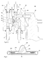
- the pressure compensation valve 60 is shown, which is a valve housing 62 having a first housing part 64 and a second housing part 66 having.
- the first housing part 64 has a first input connection 68 and a first output connection 70.
- the second housing part 66 has a second input connection 72 and a second output connection 74.
- the terminals 68 to 74 are formed as hose nozzles, which are screwed to the valve housing 62.
- the first input port 68 is connected to the supply line 34, see also FIG. 1 , connected.
- the output port 70 is connected via an intermediate line 76 to the constant pressure valve 50.
- the input port 72 is connected to the discharge line 48 and the output port 74 via an intermediate line 78 to the second constant pressure valve 52.
- a first flow path for the fresh dialysis fluid and in the second housing part 66, a second flow path for the used dialysis fluid is formed.
- the first housing part 64 is penetrated by a bore 80. Radially to this, a fluid chamber 82 is introduced into the first housing part 64, which extends toward the second housing part 66.
- the second housing part 66 also has a fluid chamber 84 which extends from the fluid chamber 82.
- the fluid chambers 82, 84 are fluidly separated from each other by a compensating element in the form of a membrane 86.
- the membrane 86 is fixed in position between the housing parts 64 and 66.
- a channel section 88 In the fluid chamber 84 opens approximately coaxially with the membrane 86, a channel section 88. This projects into sections in the fluid chamber 84 and defines an annular space therein. Into the channel section 88, the membrane 86 is immersed with a conical membrane projection 90. The channel section 88 is formed by a blind hole, in which a further blind hole opens approximately radially thereto, which is connected to the second output terminal 74. Radially into the fluid chamber 84 opens a bore 92, which is connected to the second input port 72. From this branches off a bypass channel in the form of a bore 94 which is introduced from the outside into the second housing part 66 and serves to connect a bypass valve 96. Spent dialyzing fluid thus flows via the second input port 72, the bore 92 into the fluid chamber 84 and from there via the channel section 88 to the second output port 74.
- the membrane 86 is rotationally symmetrical with an approximately circular cylindrical cross-section. On the circumference, it has a piping 98, over which it can be fixed between the housing parts 64 and 66 and additionally serves as a sealing element.
- the diaphragm projection 90 is formed coaxially with the diaphragm 86 and has a frusto-conical outer circumferential surface 100 and a rounded end face 102. When viewed in the radial direction, the diaphragm projection 90 is adjoined by an annular surface as a stop shoulder 104, which faces the channel section 88, see also FIG FIG. 2 , can strike to close the channel section 88, which is explained in more detail below. Following the stop shoulder 104, viewed in the radial direction, an annular groove 106 is introduced, through which a wall thickness of the membrane 86 is reduced to increase flexibility.
- the channel portion 88 of the first housing portion 64 has an orifice 108 with a frusto-conical inner surface 110 extending in a direction away from the membrane 86 FIG. 2 , rejuvenated.
- the end face of the channel portion 88 is followed by the mouth opening 108 an annular valve seat surface 112, to which the membrane 86 with the stop shoulder 104, see FIG. 3 , can be applied.
- the peripheral surface 114 radially adjoining the valve seat surface is frusto-conical and widens in a direction away from the diaphragm 86, see FIG FIG. 2 ,
- the fluid chamber 82 of the first housing part 64 is formed as a radial bore and has about twice the diameter of the bore 80, see FIG. 2 , Towards the second housing part 64, the fluid chamber 82 widens with a frustoconical inner lateral surface 16.
- the first housing part 64 further has an approximately circular-cylindrical cross-section housing projection 118, which is coaxially penetrated by the fluid chamber 82. This immersed in the assembled state of the housing parts 64 and 66 in a housing recess 120 of the second housing part 66 a. Front side of the housing projection 118, an annular groove 122 is introduced. Furthermore, a further annular groove 124 is introduced on the bottom side of the housing recess 120.
- bypass valve 96 is also preferably bolted to the valve housing 62.
- the setting of a constant pressure (admission pressure) for the pumps 12 and 14 and the ultrafiltration pump 59 is made possible.
- Positive range means that the pressure on the input side is greater than 0.
- the balancing chambers 18 and 20 can thus for example consist of a softer material and / or be made thinner and / or have less struts.
- the pressurized components of the dialysis machine can furthermore also be cost-effective injection-molded parts.
- the lines of the dialysis machine 1 can consist of cost-effective, comparatively thin-walled silicone tubes, which for example have a wall thickness of between 2 to 2.5 mm. So far, silicone tubes that are used for a dialysis machine, usually have a wall thickness of 3mm.
- FIG. 5 is a pressure difference 126 of the dialysis machine 1 according to the invention between the flow path with the used dialysis fluid and the flow path with the fresh dialysis fluid over time shown. It can be seen that the pressure difference 126 has small fluctuations. In contrast, at a pressure difference of 128 from a dialysis machine of the prior art, large fluctuations can be seen. Furthermore, the FIG. 5 a set resistance coefficient 130 can be removed.
- the table according to FIG. 6a shows mean values given for the average ultrafiltration rate (UF) deviation (ml / hour) in data sheets of known devices (Type I and Type II). Accordingly, the deviation of the ultrafiltration amount in known dialysis machines with increasing operating time is relatively high. In contrast, remains FIG. 6b the ultrafiltration amount in the dialysis machine 1 according to the invention over the operating time substantially constant.
- UF ultrafiltration rate
- a pressure compensation valve for a dialysis machine.
- This has a valve housing in which a flow path with fresh dialysis fluid is separated from a flow path with spent dialysis fluid through a membrane.
- the membrane and the valve housing are designed such that a pressure equalization is possible.
- the membrane is designed such that during operation no or reduced vibrations and / or no or reduced noise emissions occur.
- a dialysis machine with such a pressure compensation valve has an accounting device, wherein the pressure compensation valve is arranged on the output side of the balancing device.
Landscapes
- Health & Medical Sciences (AREA)
- Heart & Thoracic Surgery (AREA)
- Engineering & Computer Science (AREA)
- Animal Behavior & Ethology (AREA)
- Public Health (AREA)
- Biomedical Technology (AREA)
- Hematology (AREA)
- Life Sciences & Earth Sciences (AREA)
- Veterinary Medicine (AREA)
- General Health & Medical Sciences (AREA)
- Anesthesiology (AREA)
- Urology & Nephrology (AREA)
- Pulmonology (AREA)
- General Engineering & Computer Science (AREA)
- Emergency Medicine (AREA)
- Vascular Medicine (AREA)
- Mechanical Engineering (AREA)
- External Artificial Organs (AREA)
Applications Claiming Priority (1)
| Application Number | Priority Date | Filing Date | Title |
|---|---|---|---|
| DE102014109639.8A DE102014109639A1 (de) | 2014-07-09 | 2014-07-09 | Ventil für ein Dialysegerät und Dialysegerät |
Publications (2)
| Publication Number | Publication Date |
|---|---|
| EP2965771A1 true EP2965771A1 (fr) | 2016-01-13 |
| EP2965771B1 EP2965771B1 (fr) | 2017-08-09 |
Family
ID=53488174
Family Applications (1)
| Application Number | Title | Priority Date | Filing Date |
|---|---|---|---|
| EP15172872.2A Active EP2965771B1 (fr) | 2014-07-09 | 2015-06-19 | Valve pour un appareil de dialyse et appareil de dialyse |
Country Status (4)
| Country | Link |
|---|---|
| US (1) | US10024442B2 (fr) |
| EP (1) | EP2965771B1 (fr) |
| CN (1) | CN105251114B (fr) |
| DE (1) | DE102014109639A1 (fr) |
Cited By (1)
| Publication number | Priority date | Publication date | Assignee | Title |
|---|---|---|---|---|
| US10632298B2 (en) | 2015-05-04 | 2020-04-28 | Carefusion 303, Inc. | Fluid infusion systems and methods |
Families Citing this family (7)
| Publication number | Priority date | Publication date | Assignee | Title |
|---|---|---|---|---|
| US10195418B2 (en) | 2014-10-10 | 2019-02-05 | Nxstage Medical, Inc. | Pinch clamp devices, methods, and systems |
| DE102018102171A1 (de) | 2018-01-31 | 2019-08-01 | B. Braun Avitum Ag | Überwachungsvorrichtung und Verfahren zur Überwachung einer extrakorporalen Blutbehandlungsvorrichtung |
| DE102019130294A1 (de) | 2019-11-11 | 2021-05-12 | Fresenius Medical Care Deutschland Gmbh | Dialysemaschine zur Durchführung einer Push-Pull-Dialysebehandlung |
| EP3991764B1 (fr) | 2020-10-27 | 2024-03-06 | Bellco S.r.l. | Débitmètre pour dosage de l'eau dans un système de dialyse |
| US12318528B2 (en) | 2020-10-30 | 2025-06-03 | Mozarc Medical Us Llc | Variable orifice fistula graft |
| EP3991770B1 (fr) | 2020-10-30 | 2024-10-30 | Bellco S.r.l. | Cassette de dialyse comportant des fonctions de pompe |
| EP4008376A1 (fr) | 2020-12-03 | 2022-06-08 | Medtronic, Inc. | Accessoire de routage de tubes flexibles pour système de dialyse péritonéale |
Citations (7)
| Publication number | Priority date | Publication date | Assignee | Title |
|---|---|---|---|---|
| US5009775A (en) * | 1988-04-13 | 1991-04-23 | Med-Tech Inc. | Method of controlling amount of removed water by ultrafiltration and control device for controlling amount of removed water by ultrafiltration in hemodialysis |
| JPH05146506A (ja) * | 1991-07-19 | 1993-06-15 | Asahi Medical Co Ltd | 血液透析装置 |
| EP0597817A2 (fr) | 1992-11-12 | 1994-05-18 | Althin Cd Medical, Inc. | Méthode et appareillage pour dialyse rénale |
| DE69328271T2 (de) * | 1992-03-23 | 2000-12-21 | Baxter International Inc., Deerfield | Flüssigkeitssteuervorrichtung mit automatischen Ventil |
| WO2002056992A1 (fr) * | 2000-11-22 | 2002-07-25 | Baxter International Inc. | Cassette a dispositif de separation solidaire |
| DE69819715T2 (de) * | 1997-06-05 | 2004-04-15 | Gambro Lundia Ab | Zweiwegeventil |
| WO2009055639A2 (fr) * | 2007-10-24 | 2009-04-30 | Baxter International Inc. | Système d'hémodialyse individuel |
Family Cites Families (1)
| Publication number | Priority date | Publication date | Assignee | Title |
|---|---|---|---|---|
| CN205127126U (zh) | 2015-07-08 | 2016-04-06 | B·布莱恩·阿维图姆股份公司 | 用于透析机的阀和透析机 |
-
2014
- 2014-07-09 DE DE102014109639.8A patent/DE102014109639A1/de not_active Withdrawn
-
2015
- 2015-06-19 EP EP15172872.2A patent/EP2965771B1/fr active Active
- 2015-07-02 US US14/790,232 patent/US10024442B2/en active Active
- 2015-07-08 CN CN201510398171.9A patent/CN105251114B/zh active Active
Patent Citations (7)
| Publication number | Priority date | Publication date | Assignee | Title |
|---|---|---|---|---|
| US5009775A (en) * | 1988-04-13 | 1991-04-23 | Med-Tech Inc. | Method of controlling amount of removed water by ultrafiltration and control device for controlling amount of removed water by ultrafiltration in hemodialysis |
| JPH05146506A (ja) * | 1991-07-19 | 1993-06-15 | Asahi Medical Co Ltd | 血液透析装置 |
| DE69328271T2 (de) * | 1992-03-23 | 2000-12-21 | Baxter International Inc., Deerfield | Flüssigkeitssteuervorrichtung mit automatischen Ventil |
| EP0597817A2 (fr) | 1992-11-12 | 1994-05-18 | Althin Cd Medical, Inc. | Méthode et appareillage pour dialyse rénale |
| DE69819715T2 (de) * | 1997-06-05 | 2004-04-15 | Gambro Lundia Ab | Zweiwegeventil |
| WO2002056992A1 (fr) * | 2000-11-22 | 2002-07-25 | Baxter International Inc. | Cassette a dispositif de separation solidaire |
| WO2009055639A2 (fr) * | 2007-10-24 | 2009-04-30 | Baxter International Inc. | Système d'hémodialyse individuel |
Cited By (1)
| Publication number | Priority date | Publication date | Assignee | Title |
|---|---|---|---|---|
| US10632298B2 (en) | 2015-05-04 | 2020-04-28 | Carefusion 303, Inc. | Fluid infusion systems and methods |
Also Published As
| Publication number | Publication date |
|---|---|
| CN105251114A (zh) | 2016-01-20 |
| US20160010755A1 (en) | 2016-01-14 |
| US10024442B2 (en) | 2018-07-17 |
| EP2965771B1 (fr) | 2017-08-09 |
| CN105251114B (zh) | 2019-08-20 |
| DE102014109639A1 (de) | 2016-01-14 |
Similar Documents
| Publication | Publication Date | Title |
|---|---|---|
| EP2965771B1 (fr) | Valve pour un appareil de dialyse et appareil de dialyse | |
| DE102009026172A1 (de) | Mehrweghahn und Verfahren zu dessen Herstellung | |
| EP2666491B2 (fr) | Appareil d'hémodialyse | |
| WO2005108146A1 (fr) | Dispositif destine a transporter du carburant d'un reservoir a un moteur a combustion interne | |
| DE102012218903A1 (de) | Hydraulische Ventilanordnung und hydraulische Maschinenanordnung mit einer derartigen Ventilanordnung | |
| EP3377167A1 (fr) | Robinet à voies multiples pourvu d'une bague de retenue multiple | |
| WO2015018524A1 (fr) | Module de type cartouche | |
| DE102013012366B3 (de) | Extrakorporale Blutbehandlungsvorrichtung | |
| DE102016006887B4 (de) | Konstantflussdrossel und Dialysegerät | |
| EP3079736B1 (fr) | Dispositif de traitement extracorporel du sang | |
| DE102018121080A1 (de) | Verfahren und Vorrichtung zur intermittierenden, pulsierenden Proportionierung einer Dialysierflüssigkeitsmischung | |
| DE102014226378A1 (de) | Elektrisch angesteuertes Druckregelventil für eine verstellbare hydrostatische Pumpe | |
| WO2018010917A1 (fr) | Dispositif de filtration de liquide | |
| DE2548759C3 (de) | Gerät zur Messung der Ultrafiltration eines Dialysators | |
| DE112013001322T5 (de) | Rückdruckregulierung | |
| DE19541220C1 (de) | Förderpumpe | |
| EP3460299B1 (fr) | Dispositif doté d'une unité de soupape, d'une unité de refoulement et d'un corps de soupape | |
| DE102011107273A1 (de) | Regelventileinrichtung mit Differenzdruckregler | |
| DE102010054765B4 (de) | Drucksteuereinrichtung | |
| EP3344309A1 (fr) | Procédé d'étalonnage et/ou de surveillance d'un capteur de débit | |
| EP4363035B1 (fr) | Élément de serrage pour un dispositif de pompe | |
| EP4156473B1 (fr) | Entraînement | |
| DE1476772A1 (de) | Druck erzeugendes Abflussventil | |
| CN205127126U (zh) | 用于透析机的阀和透析机 | |
| DE102020108755A1 (de) | Pumpe mit elektroaktiven Polymeren |
Legal Events
| Date | Code | Title | Description |
|---|---|---|---|
| PUAI | Public reference made under article 153(3) epc to a published international application that has entered the european phase |
Free format text: ORIGINAL CODE: 0009012 |
|
| AK | Designated contracting states |
Kind code of ref document: A1 Designated state(s): AL AT BE BG CH CY CZ DE DK EE ES FI FR GB GR HR HU IE IS IT LI LT LU LV MC MK MT NL NO PL PT RO RS SE SI SK SM TR |
|
| AX | Request for extension of the european patent |
Extension state: BA ME |
|
| 17P | Request for examination filed |
Effective date: 20160504 |
|
| RBV | Designated contracting states (corrected) |
Designated state(s): AL AT BE BG CH CY CZ DE DK EE ES FI FR GB GR HR HU IE IS IT LI LT LU LV MC MK MT NL NO PL PT RO RS SE SI SK SM TR |
|
| REG | Reference to a national code |
Ref country code: DE Ref legal event code: R079 Ref document number: 502015001614 Country of ref document: DE Free format text: PREVIOUS MAIN CLASS: A61M0001160000 Ipc: F16K0007120000 |
|
| RIC1 | Information provided on ipc code assigned before grant |
Ipc: F16K 7/12 20060101AFI20161212BHEP Ipc: A61M 39/22 20060101ALI20161212BHEP Ipc: F16K 47/04 20060101ALI20161212BHEP Ipc: A61M 1/14 20060101ALI20161212BHEP Ipc: A61M 39/24 20060101ALI20161212BHEP |
|
| GRAP | Despatch of communication of intention to grant a patent |
Free format text: ORIGINAL CODE: EPIDOSNIGR1 |
|
| INTG | Intention to grant announced |
Effective date: 20170207 |
|
| GRAS | Grant fee paid |
Free format text: ORIGINAL CODE: EPIDOSNIGR3 |
|
| GRAA | (expected) grant |
Free format text: ORIGINAL CODE: 0009210 |
|
| AK | Designated contracting states |
Kind code of ref document: B1 Designated state(s): AL AT BE BG CH CY CZ DE DK EE ES FI FR GB GR HR HU IE IS IT LI LT LU LV MC MK MT NL NO PL PT RO RS SE SI SK SM TR |
|
| REG | Reference to a national code |
Ref country code: GB Ref legal event code: FG4D Free format text: NOT ENGLISH |
|
| REG | Reference to a national code |
Ref country code: CH Ref legal event code: EP Ref country code: AT Ref legal event code: REF Ref document number: 917230 Country of ref document: AT Kind code of ref document: T Effective date: 20170815 |
|
| REG | Reference to a national code |
Ref country code: IE Ref legal event code: FG4D Free format text: LANGUAGE OF EP DOCUMENT: GERMAN |
|
| REG | Reference to a national code |
Ref country code: DE Ref legal event code: R096 Ref document number: 502015001614 Country of ref document: DE |
|
| REG | Reference to a national code |
Ref country code: SE Ref legal event code: TRGR |
|
| REG | Reference to a national code |
Ref country code: NL Ref legal event code: MP Effective date: 20170809 |
|
| REG | Reference to a national code |
Ref country code: LT Ref legal event code: MG4D |
|
| PG25 | Lapsed in a contracting state [announced via postgrant information from national office to epo] |
Ref country code: NL Free format text: LAPSE BECAUSE OF FAILURE TO SUBMIT A TRANSLATION OF THE DESCRIPTION OR TO PAY THE FEE WITHIN THE PRESCRIBED TIME-LIMIT Effective date: 20170809 Ref country code: HR Free format text: LAPSE BECAUSE OF FAILURE TO SUBMIT A TRANSLATION OF THE DESCRIPTION OR TO PAY THE FEE WITHIN THE PRESCRIBED TIME-LIMIT Effective date: 20170809 Ref country code: NO Free format text: LAPSE BECAUSE OF FAILURE TO SUBMIT A TRANSLATION OF THE DESCRIPTION OR TO PAY THE FEE WITHIN THE PRESCRIBED TIME-LIMIT Effective date: 20171109 Ref country code: LT Free format text: LAPSE BECAUSE OF FAILURE TO SUBMIT A TRANSLATION OF THE DESCRIPTION OR TO PAY THE FEE WITHIN THE PRESCRIBED TIME-LIMIT Effective date: 20170809 Ref country code: FI Free format text: LAPSE BECAUSE OF FAILURE TO SUBMIT A TRANSLATION OF THE DESCRIPTION OR TO PAY THE FEE WITHIN THE PRESCRIBED TIME-LIMIT Effective date: 20170809 |
|
| PG25 | Lapsed in a contracting state [announced via postgrant information from national office to epo] |
Ref country code: LV Free format text: LAPSE BECAUSE OF FAILURE TO SUBMIT A TRANSLATION OF THE DESCRIPTION OR TO PAY THE FEE WITHIN THE PRESCRIBED TIME-LIMIT Effective date: 20170809 Ref country code: BG Free format text: LAPSE BECAUSE OF FAILURE TO SUBMIT A TRANSLATION OF THE DESCRIPTION OR TO PAY THE FEE WITHIN THE PRESCRIBED TIME-LIMIT Effective date: 20171109 Ref country code: RS Free format text: LAPSE BECAUSE OF FAILURE TO SUBMIT A TRANSLATION OF THE DESCRIPTION OR TO PAY THE FEE WITHIN THE PRESCRIBED TIME-LIMIT Effective date: 20170809 Ref country code: IS Free format text: LAPSE BECAUSE OF FAILURE TO SUBMIT A TRANSLATION OF THE DESCRIPTION OR TO PAY THE FEE WITHIN THE PRESCRIBED TIME-LIMIT Effective date: 20171209 Ref country code: PL Free format text: LAPSE BECAUSE OF FAILURE TO SUBMIT A TRANSLATION OF THE DESCRIPTION OR TO PAY THE FEE WITHIN THE PRESCRIBED TIME-LIMIT Effective date: 20170809 Ref country code: GR Free format text: LAPSE BECAUSE OF FAILURE TO SUBMIT A TRANSLATION OF THE DESCRIPTION OR TO PAY THE FEE WITHIN THE PRESCRIBED TIME-LIMIT Effective date: 20171110 Ref country code: ES Free format text: LAPSE BECAUSE OF FAILURE TO SUBMIT A TRANSLATION OF THE DESCRIPTION OR TO PAY THE FEE WITHIN THE PRESCRIBED TIME-LIMIT Effective date: 20170809 |
|
| PG25 | Lapsed in a contracting state [announced via postgrant information from national office to epo] |
Ref country code: RO Free format text: LAPSE BECAUSE OF FAILURE TO SUBMIT A TRANSLATION OF THE DESCRIPTION OR TO PAY THE FEE WITHIN THE PRESCRIBED TIME-LIMIT Effective date: 20170809 Ref country code: DK Free format text: LAPSE BECAUSE OF FAILURE TO SUBMIT A TRANSLATION OF THE DESCRIPTION OR TO PAY THE FEE WITHIN THE PRESCRIBED TIME-LIMIT Effective date: 20170809 Ref country code: CZ Free format text: LAPSE BECAUSE OF FAILURE TO SUBMIT A TRANSLATION OF THE DESCRIPTION OR TO PAY THE FEE WITHIN THE PRESCRIBED TIME-LIMIT Effective date: 20170809 |
|
| REG | Reference to a national code |
Ref country code: DE Ref legal event code: R097 Ref document number: 502015001614 Country of ref document: DE |
|
| PG25 | Lapsed in a contracting state [announced via postgrant information from national office to epo] |
Ref country code: SK Free format text: LAPSE BECAUSE OF FAILURE TO SUBMIT A TRANSLATION OF THE DESCRIPTION OR TO PAY THE FEE WITHIN THE PRESCRIBED TIME-LIMIT Effective date: 20170809 Ref country code: EE Free format text: LAPSE BECAUSE OF FAILURE TO SUBMIT A TRANSLATION OF THE DESCRIPTION OR TO PAY THE FEE WITHIN THE PRESCRIBED TIME-LIMIT Effective date: 20170809 Ref country code: SM Free format text: LAPSE BECAUSE OF FAILURE TO SUBMIT A TRANSLATION OF THE DESCRIPTION OR TO PAY THE FEE WITHIN THE PRESCRIBED TIME-LIMIT Effective date: 20170809 |
|
| PLBE | No opposition filed within time limit |
Free format text: ORIGINAL CODE: 0009261 |
|
| STAA | Information on the status of an ep patent application or granted ep patent |
Free format text: STATUS: NO OPPOSITION FILED WITHIN TIME LIMIT |
|
| 26N | No opposition filed |
Effective date: 20180511 |
|
| PG25 | Lapsed in a contracting state [announced via postgrant information from national office to epo] |
Ref country code: SI Free format text: LAPSE BECAUSE OF FAILURE TO SUBMIT A TRANSLATION OF THE DESCRIPTION OR TO PAY THE FEE WITHIN THE PRESCRIBED TIME-LIMIT Effective date: 20170809 |
|
| PG25 | Lapsed in a contracting state [announced via postgrant information from national office to epo] |
Ref country code: MT Free format text: LAPSE BECAUSE OF FAILURE TO SUBMIT A TRANSLATION OF THE DESCRIPTION OR TO PAY THE FEE WITHIN THE PRESCRIBED TIME-LIMIT Effective date: 20170809 |
|
| REG | Reference to a national code |
Ref country code: CH Ref legal event code: PL |
|
| REG | Reference to a national code |
Ref country code: BE Ref legal event code: MM Effective date: 20180630 |
|
| REG | Reference to a national code |
Ref country code: IE Ref legal event code: MM4A |
|
| PG25 | Lapsed in a contracting state [announced via postgrant information from national office to epo] |
Ref country code: LU Free format text: LAPSE BECAUSE OF NON-PAYMENT OF DUE FEES Effective date: 20180619 Ref country code: MC Free format text: LAPSE BECAUSE OF FAILURE TO SUBMIT A TRANSLATION OF THE DESCRIPTION OR TO PAY THE FEE WITHIN THE PRESCRIBED TIME-LIMIT Effective date: 20170809 |
|
| PG25 | Lapsed in a contracting state [announced via postgrant information from national office to epo] |
Ref country code: IE Free format text: LAPSE BECAUSE OF NON-PAYMENT OF DUE FEES Effective date: 20180619 Ref country code: LI Free format text: LAPSE BECAUSE OF NON-PAYMENT OF DUE FEES Effective date: 20180630 Ref country code: CH Free format text: LAPSE BECAUSE OF NON-PAYMENT OF DUE FEES Effective date: 20180630 Ref country code: FR Free format text: LAPSE BECAUSE OF NON-PAYMENT OF DUE FEES Effective date: 20180630 |
|
| PG25 | Lapsed in a contracting state [announced via postgrant information from national office to epo] |
Ref country code: BE Free format text: LAPSE BECAUSE OF NON-PAYMENT OF DUE FEES Effective date: 20180630 |
|
| GBPC | Gb: european patent ceased through non-payment of renewal fee |
Effective date: 20190619 |
|
| PG25 | Lapsed in a contracting state [announced via postgrant information from national office to epo] |
Ref country code: TR Free format text: LAPSE BECAUSE OF FAILURE TO SUBMIT A TRANSLATION OF THE DESCRIPTION OR TO PAY THE FEE WITHIN THE PRESCRIBED TIME-LIMIT Effective date: 20170809 |
|
| PG25 | Lapsed in a contracting state [announced via postgrant information from national office to epo] |
Ref country code: GB Free format text: LAPSE BECAUSE OF NON-PAYMENT OF DUE FEES Effective date: 20190619 |
|
| PG25 | Lapsed in a contracting state [announced via postgrant information from national office to epo] |
Ref country code: PT Free format text: LAPSE BECAUSE OF FAILURE TO SUBMIT A TRANSLATION OF THE DESCRIPTION OR TO PAY THE FEE WITHIN THE PRESCRIBED TIME-LIMIT Effective date: 20170809 |
|
| PG25 | Lapsed in a contracting state [announced via postgrant information from national office to epo] |
Ref country code: MK Free format text: LAPSE BECAUSE OF NON-PAYMENT OF DUE FEES Effective date: 20170809 Ref country code: CY Free format text: LAPSE BECAUSE OF FAILURE TO SUBMIT A TRANSLATION OF THE DESCRIPTION OR TO PAY THE FEE WITHIN THE PRESCRIBED TIME-LIMIT Effective date: 20170809 Ref country code: HU Free format text: LAPSE BECAUSE OF FAILURE TO SUBMIT A TRANSLATION OF THE DESCRIPTION OR TO PAY THE FEE WITHIN THE PRESCRIBED TIME-LIMIT; INVALID AB INITIO Effective date: 20150619 |
|
| PG25 | Lapsed in a contracting state [announced via postgrant information from national office to epo] |
Ref country code: AL Free format text: LAPSE BECAUSE OF FAILURE TO SUBMIT A TRANSLATION OF THE DESCRIPTION OR TO PAY THE FEE WITHIN THE PRESCRIBED TIME-LIMIT Effective date: 20170809 |
|
| REG | Reference to a national code |
Ref country code: AT Ref legal event code: MM01 Ref document number: 917230 Country of ref document: AT Kind code of ref document: T Effective date: 20200619 |
|
| PG25 | Lapsed in a contracting state [announced via postgrant information from national office to epo] |
Ref country code: AT Free format text: LAPSE BECAUSE OF NON-PAYMENT OF DUE FEES Effective date: 20200619 |
|
| P01 | Opt-out of the competence of the unified patent court (upc) registered |
Free format text: CASE NUMBER: APP_5270/2025 Effective date: 20250131 |
|
| PGFP | Annual fee paid to national office [announced via postgrant information from national office to epo] |
Ref country code: DE Payment date: 20250618 Year of fee payment: 11 |
|
| PGFP | Annual fee paid to national office [announced via postgrant information from national office to epo] |
Ref country code: SE Payment date: 20250618 Year of fee payment: 11 |
|
| PGFP | Annual fee paid to national office [announced via postgrant information from national office to epo] |
Ref country code: IT Payment date: 20250630 Year of fee payment: 11 |