EP2965788B1 - Motorisierter aktuator für einen feuerlöscher - Google Patents
Motorisierter aktuator für einen feuerlöscher Download PDFInfo
- Publication number
- EP2965788B1 EP2965788B1 EP15176050.1A EP15176050A EP2965788B1 EP 2965788 B1 EP2965788 B1 EP 2965788B1 EP 15176050 A EP15176050 A EP 15176050A EP 2965788 B1 EP2965788 B1 EP 2965788B1
- Authority
- EP
- European Patent Office
- Prior art keywords
- fire extinguisher
- cutter
- drive shaft
- activation device
- burst disc
- Prior art date
- Legal status (The legal status is an assumption and is not a legal conclusion. Google has not performed a legal analysis and makes no representation as to the accuracy of the status listed.)
- Active
Links
Images




Classifications
-
- A—HUMAN NECESSITIES
- A62—LIFE-SAVING; FIRE-FIGHTING
- A62C—FIRE-FIGHTING
- A62C37/00—Control of fire-fighting equipment
- A62C37/36—Control of fire-fighting equipment an actuating signal being generated by a sensor separate from an outlet device
- A62C37/46—Construction of the actuator
-
- A—HUMAN NECESSITIES
- A62—LIFE-SAVING; FIRE-FIGHTING
- A62C—FIRE-FIGHTING
- A62C13/00—Portable extinguishers which are permanently pressurised or pressurised immediately before use
- A62C13/62—Portable extinguishers which are permanently pressurised or pressurised immediately before use with a single permanently pressurised container
- A62C13/64—Portable extinguishers which are permanently pressurised or pressurised immediately before use with a single permanently pressurised container the extinguishing material being released by means of a valve
-
- A—HUMAN NECESSITIES
- A62—LIFE-SAVING; FIRE-FIGHTING
- A62C—FIRE-FIGHTING
- A62C35/00—Permanently-installed equipment
- A62C35/02—Permanently-installed equipment with containers for delivering the extinguishing substance
- A62C35/11—Permanently-installed equipment with containers for delivering the extinguishing substance controlled by a signal from the danger zone
- A62C35/13—Permanently-installed equipment with containers for delivering the extinguishing substance controlled by a signal from the danger zone with a finite supply of extinguishing material
-
- A—HUMAN NECESSITIES
- A62—LIFE-SAVING; FIRE-FIGHTING
- A62C—FIRE-FIGHTING
- A62C3/00—Fire prevention, containment or extinguishing specially adapted for particular objects or places
- A62C3/07—Fire prevention, containment or extinguishing specially adapted for particular objects or places in vehicles, e.g. in road vehicles
- A62C3/08—Fire prevention, containment or extinguishing specially adapted for particular objects or places in vehicles, e.g. in road vehicles in aircraft
Definitions
- the subject matter disclosed herein relates to a fire extinguisher actuator. More specifically, the subject matter disclosed relates to a fire extinguisher actuator that activates the release of a fire extinguishing agent.
- hermetically sealed fire extinguishers are typically activated by direct explosive impingement energy using a pyrotechnic trigger device, such as a pyrotechnic cartridge or squib.
- a pyrotechnic trigger device such as a pyrotechnic cartridge or squib.
- the impingement energy is focused on a dome-shaped fire extinguisher outlet burst disc such that the fire extinguisher outlet burst disc will rupture as a result of the impingement.
- the fire extinguisher outlet burst disc is typically fabricated from corrosion resistant steel.
- the pyrotechnic trigger device is retained in a discharge head in such a manner that it directly faces the fire extinguisher outlet burst disc.
- the discharge head is attached to an outlet of the fire extinguisher and is typically used to direct the flow of extinguishing agent to an aircraft interface, such as plumbing or tubing, which directs the extinguishing agent to a desired location.
- a filter screen is located within the discharge head to catch any large fire extinguisher outlet burst disc fragments created as a result of the explosive impingement energy.
- pyrotechnic trigger devices can be effective; however, pyrotechnic trigger devices require special handling procedures and training that add to overall aircraft management and maintenance costs. Additionally, pyrotechnic trigger devices may have a limited expected life span and thus require periodic replacement.
- US 6164383 A discloses a fire extinguisher which uses an explosive squib or an electronically driven solenoid to drive a firing pin.
- DE 405777 C1 discloses a device for delayed activation of a valve which includes a motor driven spindle.
- a fire extinguisher comprising a fire extinguisher actuator assembly is provided as defined by claim 1.
- a method of installing a fire extinguisher actuator assembly in a fire extinguisher is provided as defined by claim 9.
- a fire extinguisher actuator assembly for a fire extinguisher is provided that is activated without a pyrotechnic trigger device.
- the fire extinguisher actuator assembly includes a motorized activation device that drives a cutter to release a pressurized fire extinguishing agent from the fire extinguisher.
- the cutter pierces a fire extinguisher outlet burst disc that retains the pressurized fire extinguishing agent in the fire extinguisher.
- the cutter may be detachably coupled to a pusher on a drive shaft of the motorized activation device such that upon piercing of the fire extinguisher outlet burst disc, the pressure of the pressurized fire extinguishing agent drives the cutter rapidly through the fire extinguisher outlet burst disc.
- Using a cutter to open a fire extinguisher outlet burst disc of a fire extinguisher may remove the need to include a debris screen in a discharge head of the fire extinguisher system, as loose fire extinguisher outlet burst disc fragments typically resulting from pyrotechnic trigger device ignition are no longer present.
- the fire extinguisher system 100 includes a fire extinguisher 102 and a discharge head 104.
- the fire extinguisher 102 includes a fire extinguisher reservoir 106 and a fire extinguisher outlet burst disc 108 that forms a discharge barrier between the fire extinguisher reservoir 106 and the discharge head 104 to retain a pressurized fire extinguishing agent within the fire extinguisher reservoir 106.
- the discharge head 104 can be interfaced to plumbing/tubing to direct fire extinguishing agent to a desired location, for example, within an aircraft.
- FIG. 2 is a detailed view of a fire extinguisher actuator assembly 200 according to an embodiment.
- the fire extinguisher actuator assembly 200 includes a cutter shuttle assembly 202 having a cutter 204 coupled to a shuttle body 206.
- the cutter shuttle assembly 202 including the cutter 204 is detained within the fire extinguisher 102 proximate the fire extinguisher outlet burst disc 108.
- the cutter shuttle assembly 202 can be detained by at least one flexible seal 210 (referred to as flexible seal 210 herein) until a force exerted by a motorized activation device 220 is sufficient to overcome a holding force of the flexible seal 210.
- the flexible seal 210 also serves as a detent to hold the cutter shuttle assembly 202 in place during shock and vibration such that the cutter 204 does not prematurely cut through the fire extinguisher outlet burst disc 108.
- Pressurized fire extinguishing agent 212 is held in the fire extinguisher reservoir 106 under internal fire extinguisher pressure 214.
- the fire extinguisher actuator assembly 200 also includes the motorized activation device 220 having a drive shaft 222 that drives a pusher 208.
- the drive shaft 222 may include helical threading to mesh with the pusher 208, and thus the drive shaft 222 may also be referred to as a helical drive shaft.
- the drive shaft 222 can also include a shaft end cap 209 to retain the pusher 208 on the drive shaft 222.
- the motorized activation device 220 is operable to rotate the drive shaft 222 and push the cutter 204 to pierce the fire extinguisher outlet burst disc 108, thereby releasing the pressurized fire extinguishing agent 212 through the discharge head 104. As can be seen in the FIG.
- the motorized activation device 220 can be mounted in the fire extinguisher reservoir 106.
- Anti-rotation guides 215 can be used to prevent the cutter shuttle assembly 202 from rotating while the motorized activation device 220 rotates the drive shaft 222.
- the anti-rotation guides 215 can be rigidly coupled to the motorized activation device 220 or another structure within the fire extinguisher 102.
- the motorized activation device 220 can be electrically driven, absent a pyrotechnic trigger device.
- the motorized activation device 220 can be a de motor, a de geared motor, a linear motor, a rotational solenoid using a ratcheted drive, or other electrical motor type known in the art.
- the fire extinguisher actuator assembly 200 can include other structure elements to support and stabilize the motorized activation device 220, as well as electrical connections, which are not depicted to simplify the drawings.
- the fire extinguisher reservoir 106 can be sized to accommodate a wide variety of installations.
- the fire extinguisher reservoir 106 can range in size from 40 cubic inches (655.5 cm 3 ) to 2,500+ cubic inches (40,968+ cm 3 ). Pressure changes within the fire extinguisher reservoir 106 can occur due to ambient temperature variations.
- the fire extinguisher 102 may be at 240 degrees F (115.6 degrees C) on the ground on a hot day and after takeoff be at -65 degrees F (-53.9 degrees C) at altitude. These temperature changes cause substantial changes to the internal fire extinguisher pressure 214.
- Example nominal pressure values of the internal fire extinguisher pressure 214 can range from between about 300 pounds-per-square-inch (2,068 kPa) to about 800 pounds-per-square-inch (5,515 kPa) at 70 degrees F (21.1 degrees C), with higher pressures at higher temperatures and lower pressures at lower temperatures.
- the internal fire extinguisher pressure 214 can drive the cutter shuttle assembly 202 to disengage with the pusher 208 and the anti-rotation guides 215 to fully open the fire extinguisher outlet burst disc 108.
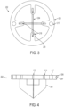
- FIG. 3 is a top view of the cutter shuttle assembly 202 according to an embodiment.
- the shuttle body 206 includes an engagement interface 219 to engage with the pusher 208 of FIG. 2 .
- the engagement interface 219 includes one or more pin holes 216.
- the engagement interface 219 can include pins, a combination of pins and pin holes, or an alternate structure to engage the pusher 208 of FIG. 2 .
- the pin holes 216 can be located in close proximity to blades of the cutter 204.
- the shuttle body 206 also includes one or more anti-rotation holes 217 to engage one or more anti-rotation guides 215 of FIG. 2 .
- the shuttle body 206 further includes a gland 207 around its circumference to hold the flexible seal 210 of FIG. 2 .
- FIG. 5 is a perspective view of the cutter 204 according to an embodiment.
- the cutter 204 includes four blades 224 intersecting at a central point 226 or cutting tip.
- the blades 224 may be uniformly spaced with about a 90 degree separation between the blades 224.
- the blades 224 may also be angled or sloped such that the central point 226 is a peak of the cutter 204.
- FIG. 6 is a perspective view of the fire extinguisher outlet burst disc 108 prior to cutting according to an embodiment.
- the fire extinguisher outlet burst disc 108 may be hermetically sealed by applying a weld to an outer perimeter of the fire extinguisher outlet burst disc 108 relative to a fire extinguisher outlet burst disc mounting assembly 211.
- FIG. 7 is a perspective view of the fire extinguisher outlet burst disc 108 after cutting according to an embodiment.
- the cutter 204 of FIG. 2 is forced through the fire extinguisher outlet burst disc 108, the fire extinguisher outlet burst disc 108 splits and opens into a plurality of petals 228.
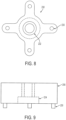
- FIG. 8 is a top view of the pusher 208 according to an embodiment.
- the pusher 208 includes four pusher pins 230 that engage with the pin holes 216 of FIGS. 3 and 4 .
- the pusher 208 also includes helical internal threads 232 to mesh with the drive shaft 222 of FIG. 2 .
- the pusher 208 may also include a recess 234 to receive the shaft end cap 209 of FIG. 2 .
- the recess 234 and the shaft end cap 209 of FIG. 2 can prevent the pusher 208 from coming off of the drive shaft 222 of FIG. 2 when the cutter 204 of FIG. 2 pushes through the fire extinguisher outlet burst disc 108 of FIG. 2 .
- FIG. 10 is a view of the motorized activation device 220 and drive shaft 222 according to an embodiment.
- Helical threads 236 can span a length of the drive shaft 222 between the motorized activation device 220 and the shaft end cap 209. Alternatively, only a portion of the drive shaft 222 upon which the pusher 208 of FIG. 2 engages may include the helical threads 236.
- the helical threads 236 are sized to engage with the helical internal threads 232 of the pusher 208 as depicted in FIG. 8 .
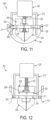
- FIG. 11 is a view of the fire extinguisher actuator assembly 200 prior to activation according to an embodiment.
- the one or more pusher pins 230 of the pusher 208 are inserted into the pin holes 216 of the shuttle body 206.
- the pusher 208 is also threaded on the drive shaft 222.
- the anti-rotation guides 215 pass through the anti-rotation holes 217 of the shuttle body 206 to prevent rotation of the cutter shuttle assembly 202.
- the flexible seal 210 holds the cutter shuttle assembly 202 in place prior to the motorized activation device 220 driving the cutter 204 to pierce the fire extinguisher outlet burst disc 108.
- FIG. 12 is a view of the fire extinguisher actuator assembly 200 after activation according to an embodiment.
- the internal fire extinguisher pressure 214 of FIG. 2 can drive the cutter 204 through the fire extinguisher outlet burst disc 108 to fully open it.
- the pusher pins 230 of the pusher 208 can disengage from the pin holes 216, and the anti-rotation guides 215 can disengage from the anti-rotation holes 217.
- the pusher 208 is captured on the end of the drive shaft 222 by the shaft end cap 209. Not shown in FIG.
- the cutter shuttle assembly 202 will be restrained internally so it cannot become a projectile if the fire extinguisher 102 is inadvertently discharged while the discharge head 104 or other protective device are not in place at the time of the inadvertent discharge.
- the cutter shuttle assembly 202 will normally be retained in, and stopped by the discharge head 104 such that it does not become a projectile.
- the fire extinguisher actuator assembly 200 can be installed in a fire extinguisher 102 according to an installation method.
- the fire extinguisher 102 includes a fire extinguisher reservoir 106 and a fire extinguisher outlet burst disc 108 that forms a discharge barrier between the fire extinguisher reservoir 106 and a discharge head 104 to retain a pressurized fire extinguishing agent 212 at within the fire extinguisher reservoir 106.
- a cutter shuttle assembly 202 that includes a cutter 204 coupled to a shuttle body 206 is detained within the fire extinguisher 102 to position the cutter 204 proximate the fire extinguisher outlet burst disc 108.
- a motorized activation device 220 including a drive shaft 222 is mounted within the fire extinguisher 102 such that the motorized activation device 220 is operable to rotate the drive shaft 222 and push the cutter 204 to pierce the fire extinguisher outlet burst disc 108, thereby releasing the pressurized fire extinguishing agent 212 through the discharge head 104.
- a pusher 208 can be arranged on the drive shaft 222.
- the cutter shuttle assembly 202 can include an engagement interface 219 to engage with the pusher 208.
- the cutter shuttle assembly 202 may be detained by at least one flexible seal 210 until a force exerted by the motorized activation device 220 is sufficient to overcome a holding force of the flexible seal 210.
- the shuttle body 206 can also include one or more anti-rotation holes 217 to engage one or more anti-rotation guides 215.
- the motorized activation device 220 can be electrically driven, absent a pyrotechnic trigger device.
Landscapes
- Health & Medical Sciences (AREA)
- Public Health (AREA)
- Business, Economics & Management (AREA)
- Emergency Management (AREA)
- Fire-Extinguishing By Fire Departments, And Fire-Extinguishing Equipment And Control Thereof (AREA)
Claims (11)
- Feuerlöscher (102), umfassend einen Feuerlöscherbehälter (106), eine Feuerlöscher-Auslassberstscheibe (108), die eine Auslassbarriere zwischen dem Feuerlöscherbehälter (106) und einem Auslasskopf (104) bildet, um ein unter Druck stehendes Feuerlöschmittel (212) in dem Feuerlöscherbehälter (106) zurückzuhalten, und eine Feuerlöscher-Aktuatorbaugruppe (200); dadurch gekennzeichnet, dass die Feuerlöscher-Aktuatorbaugruppe (200) Folgendes umfasst:ein Schneidwerkzeug (204), das innerhalb des Feuerlöschers (102) in der Nähe der Feuerlöscher-Auslassberstscheibe (108) positioniert ist, wobei das Schneidwerkzeug (204) mit einem Pendelkörper (206) gekoppelt ist, um eine Schneidwerkzeug-Pendelbaugruppe (202) zu bilden, und die Schneidwerkzeug-Pendelbaugruppe (202) ferner eine Eingriffsschnittstelle (219) umfasst, um mit einem Drücker (208) auf einer Antriebswelle (222) in Eingriff zu kommen, und die Schneidwerkzeug-Pendelbaugruppe (202) im Inneren eingeschränkt oder durch den Auslasskopf (104) zurückgehalten wird; undeine motorisierte Aktivierungsvorrichtung (220), umfassend eine Antriebswelle (222), wobei die motorisierte Aktivierungsvorrichtung (220) betätigbar ist, um die Antriebswelle (222) zu drehen und das Schneidwerkzeug (204) zu drücken, um die Feuerlöscher-Auslassberstscheibe (108) zu durchstoßen, wodurch das unter Druck stehende Feuerlöschmittel (212) durch den Auslasskopf (104) freigesetzt wird.
- Feuerlöscher (102) nach Anspruch 1, wobei die Antriebswelle (222) eine schraubenförmige Antriebswelle ist und ferner eine Wellenendkappe (209) umfasst, um den Drücker (208) auf der Antriebswelle (222) zurückzuhalten.
- Feuerlöscher (102) nach Anspruch 1, wobei die Eingriffsschnittstelle (219) ein oder mehrere Stiftlöcher (216) umfasst und der Drücker (208) einen oder mehrere Drückerstifte (230) umfasst, die in das eine oder die mehreren Stiftlöcher (216) eingreifen.
- Feuerlöscher (102) nach Anspruch 3, wobei der Pendelkörper (206) ferner ein oder mehrere Verdrehsicherungslöcher (217) umfasst, die in eine oder mehrere Verdrehsicherungsführungen (215) eingreifen.
- Feuerlöscher (102) nach Anspruch 4, wobei die eine oder die mehreren Verdrehsicherungsführungen (215) mit der motorisierten Aktivierungsvorrichtung (220) gekoppelt sind.
- Feuerlöscher (102) nach einem der Ansprüche 3 bis 5, wobei die Schneidwerkzeug-Pendelbaugruppe (202) durch mindestens eine flexible Dichtung (210) festgehalten wird, bis eine durch die motorisierte Aktivierungsvorrichtung (220) ausgeübte Kraft ausreicht, um eine Haltekraft der mindestens einen flexiblen Dichtung (210) zu überwinden.
- Feuerlöscher (102) nach einem der vorhergehenden Ansprüche, wobei die Feuerlöscher-Auslassberstscheibe (108) hermetisch abgedichtet ist.
- Feuerlöscher (102) nach einem der vorhergehenden Ansprüche, wobei die motorisierte Aktivierungsvorrichtung (220) elektrisch angetrieben wird, ohne dass eine pyrotechnische Auslösevorrichtung vorhanden ist.
- Verfahren zum Installieren einer Feuerlöscher-Aktuatorbaugruppe (200) in einem Feuerlöscher (102), wobei der Feuerlöscher (102) einen Feuerlöscherbehälter (106) und eine Feuerlöscher-Auslassberstscheibe (108) umfasst, die eine Auslassbarriere zwischen dem Feuerlöscherbehälter (106) und einem Auslasskopf (104) bildet, um ein unter Druck stehendes Feuerlöschmittel (212) in dem Feuerlöscherbehälter (106) zurückzuhalten, wobei das Verfahren gekennzeichnet ist durch:Positionieren eines Schneidwerkzeugs (204) innerhalb des Feuerlöschers (102) in der Nähe der Feuerlöscher-Auslassberstscheibe (108), wobei das Schneidwerkzeug (204) mit einem Pendelkörper (206) gekoppelt ist, um eine Schneidwerkzeug-Pendelbaugruppe (202) zu bilden, und die Schneidwerkzeug-Pendelbaugruppe (202) ferner eine Eingriffsschnittstelle (219) umfasst, um mit einem Drücker (208) auf einer Antriebswelle (222) in Eingriff zu kommen, und die Schneidwerkzeug-Pendelbaugruppe (202) im Inneren eingeschränkt oder durch den Auslasskopf (104) zurückgehalten wird; undMontieren einer motorisierten Aktivierungsvorrichtung (220), die die Antriebswelle (222) umfasst, innerhalb des Feuerlöschers (102), sodass die motorisierte Aktivierungsvorrichtung (220) betätigbar ist, um die Antriebswelle (222) zu drehen und das Schneidwerkzeug (204) zu drücken, um die Feuerlöscher-Auslassberstscheibe (108) zu durchstoßen, wodurch das unter Druck stehende Feuerlöschmittel (212) durch den Auslasskopf (104) freigesetzt wird.
- Verfahren nach Anspruch 9, wobei die Schneidwerkzeug-Pendelbaugruppe (202) durch mindestens eine flexible Dichtung (210) festgehalten wird, bis eine durch die motorisierte Aktivierungsvorrichtung (220) ausgeübte Kraft ausreicht, um eine Haltekraft der mindestens einen flexiblen Dichtung (210) zu überwinden, und der Pendelkörper (206) ferner ein oder mehrere Verdrehsicherungslöcher (217) umfasst, um in eine oder mehrere Verdrehsicherungsführungen (215) einzugreifen.
- Verfahren nach einem der Ansprüche 9 oder 10, wobei die motorisierte Aktivierungsvorrichtung (220) elektrisch angetrieben wird, ohne dass eine pyrotechnische Auslösevorrichtung vorhanden ist.
Applications Claiming Priority (1)
| Application Number | Priority Date | Filing Date | Title |
|---|---|---|---|
| US14/328,810 US9821183B2 (en) | 2014-07-11 | 2014-07-11 | Motorized actuator for a fire extinguisher |
Publications (2)
| Publication Number | Publication Date |
|---|---|
| EP2965788A1 EP2965788A1 (de) | 2016-01-13 |
| EP2965788B1 true EP2965788B1 (de) | 2024-02-28 |
Family
ID=53610769
Family Applications (1)
| Application Number | Title | Priority Date | Filing Date |
|---|---|---|---|
| EP15176050.1A Active EP2965788B1 (de) | 2014-07-11 | 2015-07-09 | Motorisierter aktuator für einen feuerlöscher |
Country Status (7)
| Country | Link |
|---|---|
| US (1) | US9821183B2 (de) |
| EP (1) | EP2965788B1 (de) |
| JP (1) | JP6539526B2 (de) |
| CN (1) | CN105268145B (de) |
| BR (1) | BR102015016520B1 (de) |
| CA (1) | CA2896600C (de) |
| ES (1) | ES2972535T3 (de) |
Families Citing this family (3)
| Publication number | Priority date | Publication date | Assignee | Title |
|---|---|---|---|---|
| US9649520B2 (en) * | 2014-07-11 | 2017-05-16 | Kidde Technologies, Inc. | Burst disc puncture pressure-imbalance actuator for a fire extinguisher |
| AT520540B1 (de) * | 2017-11-14 | 2019-05-15 | Hoerbiger Kompressortech Hold | Elektromagnetische Auslösung |
| US20250229115A1 (en) * | 2024-01-16 | 2025-07-17 | Kidde Technologies Inc. | Integral outlet fire extinguisher assembly |
Family Cites Families (46)
| Publication number | Priority date | Publication date | Assignee | Title |
|---|---|---|---|---|
| US1918191A (en) | 1931-04-11 | 1933-07-11 | Charles L Paulus | Fire extinguisher |
| US3948540A (en) | 1972-08-04 | 1976-04-06 | Eaton Corporation | Controlled flow fluid supply for occupant restraint systems |
| GB1567895A (en) | 1978-04-26 | 1980-05-21 | Glover & Co Ltd T | Operating head for a fire extinguisher |
| GB2048062B (en) | 1979-03-19 | 1983-09-01 | Rampart Eng Co Ltd | Operating head for firing extinguisher |
| US4492103A (en) | 1983-02-11 | 1985-01-08 | Bs&B Safety Systems, Inc. | Apparatus for manufacturing rupture disks |
| US4620598A (en) | 1983-10-07 | 1986-11-04 | Reeder Frank F | Disposable fire extinguisher |
| US4596289A (en) | 1985-05-10 | 1986-06-24 | Johnson Kimball W | Quick response automatic fire sprinkler head |
| FR2608720B1 (fr) * | 1986-12-18 | 1989-03-03 | Electricite De France | Dispositif de securite a membrane a couteau d'eclatement amont actif |
| DE3826300A1 (de) | 1988-08-03 | 1988-12-29 | Rusch Hans Joachim | Elektromechanische verzoegerungseinrichtung zur betaetigung eines schnelloeffnungsventiles |
| US5010911A (en) * | 1989-12-15 | 1991-04-30 | Wormald U.S., Inc. | Electromagnetic valve operator |
| DE4005777C1 (de) * | 1990-02-23 | 1991-05-16 | Total Walther Feuerschutz Gmbh, 5000 Koeln, De | |
| US5230531A (en) * | 1990-10-22 | 1993-07-27 | Oea, Inc. | Gas generator ignition assembly using a projectile |
| US5458202A (en) | 1993-09-09 | 1995-10-17 | Systron Donner Corporation | Pressurized extinguishant release device with rolling diaphragm |
| US5615743A (en) | 1994-05-24 | 1997-04-01 | Katsutoshi Matsumoto | Fire extinguisher |
| US5462307A (en) | 1994-12-27 | 1995-10-31 | General Motors Corporation | Supplemental inflation restraint inflator |
| JPH08238330A (ja) | 1995-03-06 | 1996-09-17 | Safety Syst:Kk | 噴射起動方法及びその消火装置 |
| IL114190A (en) | 1995-06-16 | 1999-08-17 | Nestle Sa | Valve assembly |
| US5918681A (en) | 1996-04-22 | 1999-07-06 | Thomas; Orrett H. | Fire extinguishing system for automotive vehicles |
| US6076610A (en) | 1996-08-30 | 2000-06-20 | Zwergel; James C. | Vehicular fire extinguishing device |
| US6394188B1 (en) | 1997-08-29 | 2002-05-28 | Fire Safety Products, Inc. | Vehicular fire extinguishing device |
| AUPO906897A0 (en) | 1997-09-09 | 1997-10-02 | F F Seeley Nominees Pty Ltd | Improvements in actuators |
| US6164383A (en) | 1999-08-17 | 2000-12-26 | Thomas; Orrett H. | Fire extinguishing system for automotive vehicles |
| IT1309902B1 (it) | 1999-12-23 | 2002-02-05 | Domenico Piatti | Estintore automatico di incendio pirotecnico. |
| FI115291B (fi) | 2002-01-17 | 2005-04-15 | Marioff Corp Oy | Venttiilielin |
| FI118987B (fi) | 2002-04-19 | 2008-06-13 | Marioff Corp Oy | Venttiilielin |
| JP3763412B2 (ja) * | 2002-09-30 | 2006-04-05 | 泰男 北村 | 台所用の消火器装置 |
| FR2850875B1 (fr) | 2003-02-07 | 2005-04-15 | Eurofeu Sa | Extincteur d'incendie comportant un reservoir en matiere plastique |
| ITRM20030473A1 (it) | 2003-10-15 | 2005-04-16 | Benedetto Fedeli | Dispositivo di perforazione di una bomboletta di gas |
| US7281672B2 (en) | 2004-03-11 | 2007-10-16 | Kidde-Fenwal, Inc. | Dual burst disk |
| US7562670B1 (en) * | 2006-04-28 | 2009-07-21 | Jones H Stephen | Flat valve for orbital applications |
| US7703471B2 (en) * | 2007-05-25 | 2010-04-27 | Tsm Corporation | Single-action discharge valve |
| EP2201984B1 (de) | 2007-10-19 | 2023-03-22 | Hideo Yoshida | Gasejektor für feuerlöscher |
| CN201350611Y (zh) * | 2008-12-22 | 2009-11-25 | 上海美瑞实业有限公司 | 一种双螺旋棘轮螺丝批的螺杆锁紧机构 |
| GB2466659A (en) | 2009-01-05 | 2010-07-07 | Robert John Wightman | A motor driven activator for a fire extinguisher |
| US8511397B2 (en) | 2010-01-12 | 2013-08-20 | Kidde Technologies, Inc. | Highly integrated data bus automatic fire extinguishing system |
| US8714175B2 (en) | 2010-02-24 | 2014-05-06 | Applied Separations, Inc. | Pressure relief system for pressure vessels |
| US20120043096A1 (en) * | 2010-03-09 | 2012-02-23 | Butz James R | Microemulsion Fire Protection Device and Method |
| US9038742B2 (en) | 2011-08-02 | 2015-05-26 | Kidde Technologies, Inc. | Suppressant actuator |
| US9302128B2 (en) | 2011-10-25 | 2016-04-05 | Kidde Technologies, Inc. | Automatic fire extinguishing system with internal dip tube |
| US9192798B2 (en) * | 2011-10-25 | 2015-11-24 | Kidde Technologies, Inc. | Automatic fire extinguishing system with gaseous and dry powder fire suppression agents |
| EP2617467A1 (de) | 2012-01-20 | 2013-07-24 | Kidde Technologies, Inc. | Feuerlöschanlage mit Mehrfachabgabe |
| JP6144062B2 (ja) * | 2012-03-13 | 2017-06-07 | 吉田 英夫 | 自動消火装置 |
| US9168406B2 (en) | 2012-03-15 | 2015-10-27 | Kidde Technologies, Inc. | Automatic actuation of a general purpose hand extinguisher |
| US9153400B2 (en) | 2013-03-15 | 2015-10-06 | Kidde Technologies, Inc. | Pneumatic detector integrated alarm and fault switch |
| US9309981B2 (en) | 2013-10-18 | 2016-04-12 | Kidde Technologies, Inc. | Poppet valve with a frangible sealing disc for a pressure vessel |
| CN103845830B (zh) * | 2014-03-31 | 2016-02-10 | 徐鹏 | 一种用于汽车自燃的自动灭火装置 |
-
2014
- 2014-07-11 US US14/328,810 patent/US9821183B2/en active Active
-
2015
- 2015-07-08 CA CA2896600A patent/CA2896600C/en active Active
- 2015-07-09 ES ES15176050T patent/ES2972535T3/es active Active
- 2015-07-09 BR BR102015016520-0A patent/BR102015016520B1/pt active IP Right Grant
- 2015-07-09 EP EP15176050.1A patent/EP2965788B1/de active Active
- 2015-07-10 CN CN201510404263.3A patent/CN105268145B/zh active Active
- 2015-07-10 JP JP2015138285A patent/JP6539526B2/ja active Active
Also Published As
| Publication number | Publication date |
|---|---|
| US20160008648A1 (en) | 2016-01-14 |
| BR102015016520B1 (pt) | 2021-10-13 |
| JP6539526B2 (ja) | 2019-07-03 |
| EP2965788A1 (de) | 2016-01-13 |
| US9821183B2 (en) | 2017-11-21 |
| BR102015016520A2 (pt) | 2016-01-12 |
| CN105268145B (zh) | 2020-03-03 |
| JP2016019732A (ja) | 2016-02-04 |
| CA2896600A1 (en) | 2016-01-11 |
| ES2972535T3 (es) | 2024-06-13 |
| CN105268145A (zh) | 2016-01-27 |
| CA2896600C (en) | 2021-12-21 |
Similar Documents
| Publication | Publication Date | Title |
|---|---|---|
| EP2965786B1 (de) | Berstplatten-druckungleichgewichtsstellglied für feuerlöscher | |
| EP2965788B1 (de) | Motorisierter aktuator für einen feuerlöscher | |
| US9539452B2 (en) | Rapid pressure diffusion actuator for a fire extinguisher | |
| TW200946804A (en) | Single-action discharge valve | |
| EP3023123B1 (de) | Tellerventil mit berstscheibe für einen druckbehälter | |
| EP2778486B1 (de) | Ventilmechanismus mit zerbrechlichem Stecker | |
| BR102016008474B1 (pt) | Válvula para controlar a liberação de supressor de fogo a partir de um recipiente pressurizado, e, aparelho | |
| EP3026309B1 (de) | Berstmembran zur verwendung in einem ventilmechanismus | |
| CA2908145C (en) | A frangible plug for use in a valve mechanism | |
| EP3209921B1 (de) | Rohrschneider | |
| CN105816980B (zh) | 用于启动灭火器的弹簧筒夹机构 | |
| JP2015181556A (ja) | スプリンクラーヘッド | |
| RU210860U1 (ru) | Импульсное устройство выпуска текучего огнетушащего вещества, находящегося под давлением в герметичной емкости |
Legal Events
| Date | Code | Title | Description |
|---|---|---|---|
| PUAI | Public reference made under article 153(3) epc to a published international application that has entered the european phase |
Free format text: ORIGINAL CODE: 0009012 |
|
| AK | Designated contracting states |
Kind code of ref document: A1 Designated state(s): AL AT BE BG CH CY CZ DE DK EE ES FI FR GB GR HR HU IE IS IT LI LT LU LV MC MK MT NL NO PL PT RO RS SE SI SK SM TR |
|
| AX | Request for extension of the european patent |
Extension state: BA ME |
|
| 17P | Request for examination filed |
Effective date: 20160713 |
|
| RBV | Designated contracting states (corrected) |
Designated state(s): AL AT BE BG CH CY CZ DE DK EE ES FI FR GB GR HR HU IE IS IT LI LT LU LV MC MK MT NL NO PL PT RO RS SE SI SK SM TR |
|
| R17P | Request for examination filed (corrected) |
Effective date: 20160713 |
|
| STAA | Information on the status of an ep patent application or granted ep patent |
Free format text: STATUS: EXAMINATION IS IN PROGRESS |
|
| 17Q | First examination report despatched |
Effective date: 20211013 |
|
| GRAP | Despatch of communication of intention to grant a patent |
Free format text: ORIGINAL CODE: EPIDOSNIGR1 |
|
| STAA | Information on the status of an ep patent application or granted ep patent |
Free format text: STATUS: GRANT OF PATENT IS INTENDED |
|
| RIC1 | Information provided on ipc code assigned before grant |
Ipc: A62C 37/46 20060101ALI20230926BHEP Ipc: A62C 13/64 20060101ALI20230926BHEP Ipc: A62C 13/78 20060101ALI20230926BHEP Ipc: A62C 3/08 20060101ALI20230926BHEP Ipc: A62C 35/13 20060101AFI20230926BHEP |
|
| INTG | Intention to grant announced |
Effective date: 20231010 |
|
| RIN1 | Information on inventor provided before grant (corrected) |
Inventor name: PORTERFIELD, JR., JOHN WRIGHT Inventor name: FRASURE, DAVID |
|
| GRAS | Grant fee paid |
Free format text: ORIGINAL CODE: EPIDOSNIGR3 |
|
| GRAA | (expected) grant |
Free format text: ORIGINAL CODE: 0009210 |
|
| STAA | Information on the status of an ep patent application or granted ep patent |
Free format text: STATUS: THE PATENT HAS BEEN GRANTED |
|
| AK | Designated contracting states |
Kind code of ref document: B1 Designated state(s): AL AT BE BG CH CY CZ DE DK EE ES FI FR GB GR HR HU IE IS IT LI LT LU LV MC MK MT NL NO PL PT RO RS SE SI SK SM TR |
|
| REG | Reference to a national code |
Ref country code: GB Ref legal event code: FG4D |
|
| REG | Reference to a national code |
Ref country code: CH Ref legal event code: EP |
|
| REG | Reference to a national code |
Ref country code: DE Ref legal event code: R096 Ref document number: 602015087687 Country of ref document: DE |
|
| REG | Reference to a national code |
Ref country code: IE Ref legal event code: FG4D |
|
| REG | Reference to a national code |
Ref country code: ES Ref legal event code: FG2A Ref document number: 2972535 Country of ref document: ES Kind code of ref document: T3 Effective date: 20240613 |
|
| REG | Reference to a national code |
Ref country code: LT Ref legal event code: MG9D |
|
| PG25 | Lapsed in a contracting state [announced via postgrant information from national office to epo] |
Ref country code: IS Free format text: LAPSE BECAUSE OF FAILURE TO SUBMIT A TRANSLATION OF THE DESCRIPTION OR TO PAY THE FEE WITHIN THE PRESCRIBED TIME-LIMIT Effective date: 20240628 |
|
| REG | Reference to a national code |
Ref country code: NL Ref legal event code: MP Effective date: 20240228 |
|
| PG25 | Lapsed in a contracting state [announced via postgrant information from national office to epo] |
Ref country code: LT Free format text: LAPSE BECAUSE OF FAILURE TO SUBMIT A TRANSLATION OF THE DESCRIPTION OR TO PAY THE FEE WITHIN THE PRESCRIBED TIME-LIMIT Effective date: 20240228 |
|
| PG25 | Lapsed in a contracting state [announced via postgrant information from national office to epo] |
Ref country code: GR Free format text: LAPSE BECAUSE OF FAILURE TO SUBMIT A TRANSLATION OF THE DESCRIPTION OR TO PAY THE FEE WITHIN THE PRESCRIBED TIME-LIMIT Effective date: 20240529 |
|
| PG25 | Lapsed in a contracting state [announced via postgrant information from national office to epo] |
Ref country code: HR Free format text: LAPSE BECAUSE OF FAILURE TO SUBMIT A TRANSLATION OF THE DESCRIPTION OR TO PAY THE FEE WITHIN THE PRESCRIBED TIME-LIMIT Effective date: 20240228 Ref country code: RS Free format text: LAPSE BECAUSE OF FAILURE TO SUBMIT A TRANSLATION OF THE DESCRIPTION OR TO PAY THE FEE WITHIN THE PRESCRIBED TIME-LIMIT Effective date: 20240528 Ref country code: NL Free format text: LAPSE BECAUSE OF FAILURE TO SUBMIT A TRANSLATION OF THE DESCRIPTION OR TO PAY THE FEE WITHIN THE PRESCRIBED TIME-LIMIT Effective date: 20240228 |
|
| PG25 | Lapsed in a contracting state [announced via postgrant information from national office to epo] |
Ref country code: RS Free format text: LAPSE BECAUSE OF FAILURE TO SUBMIT A TRANSLATION OF THE DESCRIPTION OR TO PAY THE FEE WITHIN THE PRESCRIBED TIME-LIMIT Effective date: 20240528 Ref country code: NO Free format text: LAPSE BECAUSE OF FAILURE TO SUBMIT A TRANSLATION OF THE DESCRIPTION OR TO PAY THE FEE WITHIN THE PRESCRIBED TIME-LIMIT Effective date: 20240528 Ref country code: NL Free format text: LAPSE BECAUSE OF FAILURE TO SUBMIT A TRANSLATION OF THE DESCRIPTION OR TO PAY THE FEE WITHIN THE PRESCRIBED TIME-LIMIT Effective date: 20240228 Ref country code: LT Free format text: LAPSE BECAUSE OF FAILURE TO SUBMIT A TRANSLATION OF THE DESCRIPTION OR TO PAY THE FEE WITHIN THE PRESCRIBED TIME-LIMIT Effective date: 20240228 Ref country code: IS Free format text: LAPSE BECAUSE OF FAILURE TO SUBMIT A TRANSLATION OF THE DESCRIPTION OR TO PAY THE FEE WITHIN THE PRESCRIBED TIME-LIMIT Effective date: 20240628 Ref country code: HR Free format text: LAPSE BECAUSE OF FAILURE TO SUBMIT A TRANSLATION OF THE DESCRIPTION OR TO PAY THE FEE WITHIN THE PRESCRIBED TIME-LIMIT Effective date: 20240228 Ref country code: GR Free format text: LAPSE BECAUSE OF FAILURE TO SUBMIT A TRANSLATION OF THE DESCRIPTION OR TO PAY THE FEE WITHIN THE PRESCRIBED TIME-LIMIT Effective date: 20240529 Ref country code: FI Free format text: LAPSE BECAUSE OF FAILURE TO SUBMIT A TRANSLATION OF THE DESCRIPTION OR TO PAY THE FEE WITHIN THE PRESCRIBED TIME-LIMIT Effective date: 20240228 Ref country code: BG Free format text: LAPSE BECAUSE OF FAILURE TO SUBMIT A TRANSLATION OF THE DESCRIPTION OR TO PAY THE FEE WITHIN THE PRESCRIBED TIME-LIMIT Effective date: 20240228 |
|
| PG25 | Lapsed in a contracting state [announced via postgrant information from national office to epo] |
Ref country code: PT Free format text: LAPSE BECAUSE OF FAILURE TO SUBMIT A TRANSLATION OF THE DESCRIPTION OR TO PAY THE FEE WITHIN THE PRESCRIBED TIME-LIMIT Effective date: 20240628 Ref country code: PL Free format text: LAPSE BECAUSE OF FAILURE TO SUBMIT A TRANSLATION OF THE DESCRIPTION OR TO PAY THE FEE WITHIN THE PRESCRIBED TIME-LIMIT Effective date: 20240228 |
|
| REG | Reference to a national code |
Ref country code: AT Ref legal event code: MK05 Ref document number: 1660711 Country of ref document: AT Kind code of ref document: T Effective date: 20240228 |
|
| PG25 | Lapsed in a contracting state [announced via postgrant information from national office to epo] |
Ref country code: SE Free format text: LAPSE BECAUSE OF FAILURE TO SUBMIT A TRANSLATION OF THE DESCRIPTION OR TO PAY THE FEE WITHIN THE PRESCRIBED TIME-LIMIT Effective date: 20240228 Ref country code: PT Free format text: LAPSE BECAUSE OF FAILURE TO SUBMIT A TRANSLATION OF THE DESCRIPTION OR TO PAY THE FEE WITHIN THE PRESCRIBED TIME-LIMIT Effective date: 20240628 Ref country code: PL Free format text: LAPSE BECAUSE OF FAILURE TO SUBMIT A TRANSLATION OF THE DESCRIPTION OR TO PAY THE FEE WITHIN THE PRESCRIBED TIME-LIMIT Effective date: 20240228 Ref country code: LV Free format text: LAPSE BECAUSE OF FAILURE TO SUBMIT A TRANSLATION OF THE DESCRIPTION OR TO PAY THE FEE WITHIN THE PRESCRIBED TIME-LIMIT Effective date: 20240228 |
|
| PG25 | Lapsed in a contracting state [announced via postgrant information from national office to epo] |
Ref country code: DK Free format text: LAPSE BECAUSE OF FAILURE TO SUBMIT A TRANSLATION OF THE DESCRIPTION OR TO PAY THE FEE WITHIN THE PRESCRIBED TIME-LIMIT Effective date: 20240228 |
|
| PG25 | Lapsed in a contracting state [announced via postgrant information from national office to epo] |
Ref country code: SM Free format text: LAPSE BECAUSE OF FAILURE TO SUBMIT A TRANSLATION OF THE DESCRIPTION OR TO PAY THE FEE WITHIN THE PRESCRIBED TIME-LIMIT Effective date: 20240228 |
|
| PG25 | Lapsed in a contracting state [announced via postgrant information from national office to epo] |
Ref country code: CZ Free format text: LAPSE BECAUSE OF FAILURE TO SUBMIT A TRANSLATION OF THE DESCRIPTION OR TO PAY THE FEE WITHIN THE PRESCRIBED TIME-LIMIT Effective date: 20240228 Ref country code: EE Free format text: LAPSE BECAUSE OF FAILURE TO SUBMIT A TRANSLATION OF THE DESCRIPTION OR TO PAY THE FEE WITHIN THE PRESCRIBED TIME-LIMIT Effective date: 20240228 |
|
| PG25 | Lapsed in a contracting state [announced via postgrant information from national office to epo] |
Ref country code: AT Free format text: LAPSE BECAUSE OF FAILURE TO SUBMIT A TRANSLATION OF THE DESCRIPTION OR TO PAY THE FEE WITHIN THE PRESCRIBED TIME-LIMIT Effective date: 20240228 |
|
| PG25 | Lapsed in a contracting state [announced via postgrant information from national office to epo] |
Ref country code: SK Free format text: LAPSE BECAUSE OF FAILURE TO SUBMIT A TRANSLATION OF THE DESCRIPTION OR TO PAY THE FEE WITHIN THE PRESCRIBED TIME-LIMIT Effective date: 20240228 |
|
| PG25 | Lapsed in a contracting state [announced via postgrant information from national office to epo] |
Ref country code: SM Free format text: LAPSE BECAUSE OF FAILURE TO SUBMIT A TRANSLATION OF THE DESCRIPTION OR TO PAY THE FEE WITHIN THE PRESCRIBED TIME-LIMIT Effective date: 20240228 Ref country code: SK Free format text: LAPSE BECAUSE OF FAILURE TO SUBMIT A TRANSLATION OF THE DESCRIPTION OR TO PAY THE FEE WITHIN THE PRESCRIBED TIME-LIMIT Effective date: 20240228 Ref country code: RO Free format text: LAPSE BECAUSE OF FAILURE TO SUBMIT A TRANSLATION OF THE DESCRIPTION OR TO PAY THE FEE WITHIN THE PRESCRIBED TIME-LIMIT Effective date: 20240228 Ref country code: EE Free format text: LAPSE BECAUSE OF FAILURE TO SUBMIT A TRANSLATION OF THE DESCRIPTION OR TO PAY THE FEE WITHIN THE PRESCRIBED TIME-LIMIT Effective date: 20240228 Ref country code: DK Free format text: LAPSE BECAUSE OF FAILURE TO SUBMIT A TRANSLATION OF THE DESCRIPTION OR TO PAY THE FEE WITHIN THE PRESCRIBED TIME-LIMIT Effective date: 20240228 Ref country code: CZ Free format text: LAPSE BECAUSE OF FAILURE TO SUBMIT A TRANSLATION OF THE DESCRIPTION OR TO PAY THE FEE WITHIN THE PRESCRIBED TIME-LIMIT Effective date: 20240228 Ref country code: AT Free format text: LAPSE BECAUSE OF FAILURE TO SUBMIT A TRANSLATION OF THE DESCRIPTION OR TO PAY THE FEE WITHIN THE PRESCRIBED TIME-LIMIT Effective date: 20240228 |
|
| REG | Reference to a national code |
Ref country code: DE Ref legal event code: R097 Ref document number: 602015087687 Country of ref document: DE |
|
| PLBE | No opposition filed within time limit |
Free format text: ORIGINAL CODE: 0009261 |
|
| STAA | Information on the status of an ep patent application or granted ep patent |
Free format text: STATUS: NO OPPOSITION FILED WITHIN TIME LIMIT |
|
| 26N | No opposition filed |
Effective date: 20241129 |
|
| PG25 | Lapsed in a contracting state [announced via postgrant information from national office to epo] |
Ref country code: MC Free format text: LAPSE BECAUSE OF FAILURE TO SUBMIT A TRANSLATION OF THE DESCRIPTION OR TO PAY THE FEE WITHIN THE PRESCRIBED TIME-LIMIT Effective date: 20240228 |
|
| REG | Reference to a national code |
Ref country code: CH Ref legal event code: PL |
|
| PG25 | Lapsed in a contracting state [announced via postgrant information from national office to epo] |
Ref country code: LU Free format text: LAPSE BECAUSE OF NON-PAYMENT OF DUE FEES Effective date: 20240709 |
|
| PG25 | Lapsed in a contracting state [announced via postgrant information from national office to epo] |
Ref country code: LU Free format text: LAPSE BECAUSE OF NON-PAYMENT OF DUE FEES Effective date: 20240709 |
|
| PG25 | Lapsed in a contracting state [announced via postgrant information from national office to epo] |
Ref country code: SI Free format text: LAPSE BECAUSE OF FAILURE TO SUBMIT A TRANSLATION OF THE DESCRIPTION OR TO PAY THE FEE WITHIN THE PRESCRIBED TIME-LIMIT Effective date: 20240228 Ref country code: BE Free format text: LAPSE BECAUSE OF NON-PAYMENT OF DUE FEES Effective date: 20240731 Ref country code: CH Free format text: LAPSE BECAUSE OF NON-PAYMENT OF DUE FEES Effective date: 20240731 |
|
| REG | Reference to a national code |
Ref country code: BE Ref legal event code: MM Effective date: 20240731 |
|
| PGFP | Annual fee paid to national office [announced via postgrant information from national office to epo] |
Ref country code: GB Payment date: 20250619 Year of fee payment: 11 |
|
| PGFP | Annual fee paid to national office [announced via postgrant information from national office to epo] |
Ref country code: FR Payment date: 20250620 Year of fee payment: 11 |
|
| PG25 | Lapsed in a contracting state [announced via postgrant information from national office to epo] |
Ref country code: IE Free format text: LAPSE BECAUSE OF NON-PAYMENT OF DUE FEES Effective date: 20240709 |
|
| PGFP | Annual fee paid to national office [announced via postgrant information from national office to epo] |
Ref country code: ES Payment date: 20250801 Year of fee payment: 11 |
|
| PGFP | Annual fee paid to national office [announced via postgrant information from national office to epo] |
Ref country code: DE Payment date: 20250620 Year of fee payment: 11 |
|
| PGFP | Annual fee paid to national office [announced via postgrant information from national office to epo] |
Ref country code: IT Payment date: 20250619 Year of fee payment: 11 |
|
| PG25 | Lapsed in a contracting state [announced via postgrant information from national office to epo] |
Ref country code: CY Free format text: LAPSE BECAUSE OF FAILURE TO SUBMIT A TRANSLATION OF THE DESCRIPTION OR TO PAY THE FEE WITHIN THE PRESCRIBED TIME-LIMIT; INVALID AB INITIO Effective date: 20150709 |
|
| PG25 | Lapsed in a contracting state [announced via postgrant information from national office to epo] |
Ref country code: HU Free format text: LAPSE BECAUSE OF FAILURE TO SUBMIT A TRANSLATION OF THE DESCRIPTION OR TO PAY THE FEE WITHIN THE PRESCRIBED TIME-LIMIT; INVALID AB INITIO Effective date: 20150709 |