EP2965862B1 - Machine-outil - Google Patents
Machine-outil Download PDFInfo
- Publication number
- EP2965862B1 EP2965862B1 EP14760475.5A EP14760475A EP2965862B1 EP 2965862 B1 EP2965862 B1 EP 2965862B1 EP 14760475 A EP14760475 A EP 14760475A EP 2965862 B1 EP2965862 B1 EP 2965862B1
- Authority
- EP
- European Patent Office
- Prior art keywords
- frame
- spindle head
- saddle
- machine tool
- processing region
- Prior art date
- Legal status (The legal status is an assumption and is not a legal conclusion. Google has not performed a legal analysis and makes no representation as to the accuracy of the status listed.)
- Active
Links
Images


Classifications
-
- B—PERFORMING OPERATIONS; TRANSPORTING
- B23—MACHINE TOOLS; METAL-WORKING NOT OTHERWISE PROVIDED FOR
- B23Q—DETAILS, COMPONENTS, OR ACCESSORIES FOR MACHINE TOOLS, e.g. ARRANGEMENTS FOR COPYING OR CONTROLLING; MACHINE TOOLS IN GENERAL CHARACTERISED BY THE CONSTRUCTION OF PARTICULAR DETAILS OR COMPONENTS; COMBINATIONS OR ASSOCIATIONS OF METAL-WORKING MACHINES, NOT DIRECTED TO A PARTICULAR RESULT
- B23Q1/00—Members which are comprised in the general build-up of a form of machine, particularly relatively large fixed members
- B23Q1/70—Stationary or movable members for carrying working-spindles for attachment of tools or work
-
- B—PERFORMING OPERATIONS; TRANSPORTING
- B23—MACHINE TOOLS; METAL-WORKING NOT OTHERWISE PROVIDED FOR
- B23Q—DETAILS, COMPONENTS, OR ACCESSORIES FOR MACHINE TOOLS, e.g. ARRANGEMENTS FOR COPYING OR CONTROLLING; MACHINE TOOLS IN GENERAL CHARACTERISED BY THE CONSTRUCTION OF PARTICULAR DETAILS OR COMPONENTS; COMBINATIONS OR ASSOCIATIONS OF METAL-WORKING MACHINES, NOT DIRECTED TO A PARTICULAR RESULT
- B23Q11/00—Accessories fitted to machine tools for keeping tools or parts of the machine in good working condition or for cooling work; Safety devices specially combined with or arranged in, or specially adapted for use in connection with, machine tools
- B23Q11/08—Protective coverings for parts of machine tools; Splash guards
-
- B—PERFORMING OPERATIONS; TRANSPORTING
- B23—MACHINE TOOLS; METAL-WORKING NOT OTHERWISE PROVIDED FOR
- B23Q—DETAILS, COMPONENTS, OR ACCESSORIES FOR MACHINE TOOLS, e.g. ARRANGEMENTS FOR COPYING OR CONTROLLING; MACHINE TOOLS IN GENERAL CHARACTERISED BY THE CONSTRUCTION OF PARTICULAR DETAILS OR COMPONENTS; COMBINATIONS OR ASSOCIATIONS OF METAL-WORKING MACHINES, NOT DIRECTED TO A PARTICULAR RESULT
- B23Q1/00—Members which are comprised in the general build-up of a form of machine, particularly relatively large fixed members
- B23Q1/25—Movable or adjustable work or tool supports
- B23Q1/44—Movable or adjustable work or tool supports using particular mechanisms
- B23Q1/56—Movable or adjustable work or tool supports using particular mechanisms with sliding pairs only, the sliding pairs being the first two elements of the mechanism
- B23Q1/60—Movable or adjustable work or tool supports using particular mechanisms with sliding pairs only, the sliding pairs being the first two elements of the mechanism two sliding pairs only, the sliding pairs being the first two elements of the mechanism
- B23Q1/62—Movable or adjustable work or tool supports using particular mechanisms with sliding pairs only, the sliding pairs being the first two elements of the mechanism two sliding pairs only, the sliding pairs being the first two elements of the mechanism with perpendicular axes, e.g. cross-slides
- B23Q1/621—Movable or adjustable work or tool supports using particular mechanisms with sliding pairs only, the sliding pairs being the first two elements of the mechanism two sliding pairs only, the sliding pairs being the first two elements of the mechanism with perpendicular axes, e.g. cross-slides a single sliding pair followed perpendicularly by a single sliding pair
- B23Q1/626—Movable or adjustable work or tool supports using particular mechanisms with sliding pairs only, the sliding pairs being the first two elements of the mechanism two sliding pairs only, the sliding pairs being the first two elements of the mechanism with perpendicular axes, e.g. cross-slides a single sliding pair followed perpendicularly by a single sliding pair followed perpendicularly by a single sliding pair
-
- B—PERFORMING OPERATIONS; TRANSPORTING
- B23—MACHINE TOOLS; METAL-WORKING NOT OTHERWISE PROVIDED FOR
- B23Q—DETAILS, COMPONENTS, OR ACCESSORIES FOR MACHINE TOOLS, e.g. ARRANGEMENTS FOR COPYING OR CONTROLLING; MACHINE TOOLS IN GENERAL CHARACTERISED BY THE CONSTRUCTION OF PARTICULAR DETAILS OR COMPONENTS; COMBINATIONS OR ASSOCIATIONS OF METAL-WORKING MACHINES, NOT DIRECTED TO A PARTICULAR RESULT
- B23Q3/00—Devices holding, supporting, or positioning work or tools, of a kind normally removable from the machine
- B23Q3/155—Arrangements for automatic insertion or removal of tools, e.g. combined with manual handling
- B23Q3/157—Arrangements for automatic insertion or removal of tools, e.g. combined with manual handling of rotary tools
- B23Q3/15713—Arrangements for automatic insertion or removal of tools, e.g. combined with manual handling of rotary tools a transfer device taking a single tool from a storage device and inserting it in a spindle
- B23Q3/1572—Arrangements for automatic insertion or removal of tools, e.g. combined with manual handling of rotary tools a transfer device taking a single tool from a storage device and inserting it in a spindle the storage device comprising rotating or circulating storing means
- B23Q3/15722—Rotary discs or drums
Definitions
- the present disclosure relates to a machine tool, and more particularly, to a machine tool which is provided with a covering device applicable to a machine tool in which an ATC and a spindle head are integrally provided.
- Document US2003/0143048A1 which forms the basis for the preamble of claim 1, discloses a machine tool comprising a covering device for protecting the machine bed from chips and coolant.
- a machine tool is a machine used to process metallic or nonmetallic materials (hereinafter, referred to as a base material) to have a shape and a dimension using appropriate tools through various types of cutting or non-cutting operations, or used to more precisely process the base material.
- the machine tool includes a table for fixing and moving the base material, and a tool post for processing the base material.
- the multitasking machine which is a single machine tool capable of performing various types of machining operations.
- the multitasking machine is provided with an automatic tool changer (ATC) capable of changing a plurality of tools mounted on a tool magazine in order to perform various types of machining operations.
- ATC automatic tool changer
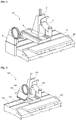
- FIG. 1 is a perspective view of a machine tool provided with an ATC 5 in the related art.
- the machine tool in the related art includes a tool post 10 including a spindle head 1, a column 2, a saddle 3, a feed unit 4, and the ATC 5, and a table 20 on which a base material is mounted.
- a processing region is defined at a front side in the machine tool where the spindle head 1 and the table 20 are positioned, and a non-processing region is defined at a rear side in the machine tool where the column 2, the saddle 3, the ATC 5, and the feed unit 4 are positioned.
- a tool for processing the base material is mounted on the spindle head 1, and the tool processes the base material by receiving rotational force from the spindle head 1.
- the spindle head 1 is mounted at a front side of the column 2, and the column 2 moves the spindle head 1 upward and downward.
- the column 2 is mounted at an upper side of the saddle 3, and the saddle 3 moves the column 2 forward and rearward. That is, as the saddle 3 moves forward and rearward, the column 2 and the spindle head 1 are also moved forward and rearward.
- the saddle 3 is mounted at an upper side of the feed unit 4, and the feed unit 4 moves the saddle 3 left and right. That is, the left and right movement of the feed unit 4 moves the saddle 3, the column 2, and the spindle head 1 left and right.
- the table 20 is provided at an upper side of the feed unit 4, and a base material, which will be processed by the spindle head 1, is mounted on the table 20.
- the position of the spindle head 1 may be changed in all directions by the movements of the column 2, the saddle 3, and the feed unit 4, and it is possible to process the base material mounted on the table 20 in all directions.
- a separate cover is installed on the ATC 5 to prevent chips or a coolant from entering the ATC 5 during a process of processing a workpiece, and protects the ATC 5.
- a cover of the ATC 5 makes the structure of the ATC 5 itself complicated, and only prevents foreign substances from entering the ATC 5, and as a result, there is a problem in that it is somewhat difficult to prevent foreign substances from entering other components, that is, components in the non-processing region.
- the present disclosure has been made in an effort to solve the above problems, and an object of the present disclosure is to provide a machine tool capable of reducing tool changing time even though a transfer axis of a feed unit is extended.
- Another object of the present disclosure is to provide a machine tool that prevents foreign substances from entering a non-processing region while processing.
- the present disclosure provides a machine tool according to claim 1 of the present application.
- the present disclosure has an effect in that the tool changing time is reduced compared to the related art even though a transfer axis is extended, and consequently, processing time is reduced, and productivity is improved.
- the present disclosure has an effect in that foreign substances are basically prevented from entering the non-processing region, thereby improving durability of the machine tool.
- FIG. 2 is a perspective view of a machine tool according to an exemplary embodiment of the present disclosure in which an ATC 150 is provided on a saddle 130
- FIG. 3 is a perspective view of the machine tool provided with a covering device 300 according to the exemplary embodiment of the present disclosure.
- the machine tool includes a tool post 100 including a spindle head 110, a column 120, the saddle 130, a feed unit 140, and the ATC 150, a table 200 on which a base material is mounted, and the covering device 300.
- a processing region is defined at a front side in the machine tool where the spindle head 110 and the table 200 are positioned, and a non-processing region is defined at a rear side in the machine tool where the column 120, the saddle 130, the ATC 150, and the feed unit 140 are positioned.
- a tool for processing the base material is mounted on the spindle head 110, and the tool processes the base material mounted on the table 200 by receiving rotational force from the spindle head 110.
- the spindle head 110 is mounted at a front side of the column 120, and the column 120 moves the spindle head 110 upward and downward.
- the column 120 is mounted at an upper side of the saddle 130, and the saddle 130 moves the column 120 forward and rearward. That is, as the saddle 130 moves forward and rearward, the column 120 and the spindle head 110 are also moved forward and rearward.
- the saddle 130 is mounted at an upper side of the feed unit 140, and the feed unit 140 moves the saddle 130 left and right. That is, the left and right movement of the feed unit 140 moves the saddle 130, the column 120, and the spindle head 110 left and right.
- the table 200 is provided at an upper side of the feed unit 140, and a base material, which will be processed by the spindle head 110, is mounted on the table 200.
- the position of the spindle head 110 may be changed in all directions by the movements of the column 120, the saddle 130, and the feed unit 140, and it is possible to process the base material mounted on the table 200 in all directions.
- an automatic tool changer (ATC) 150 which changes the tools to be mounted on the spindle head 110, is provided at one side of the saddle 130 in order to reduce the time required to change the tools.
- the ATC 150 is a device capable of changing tools to be clamped to the spindle head 110 after a plurality of tools is mounted in a tool magazine, and the saddle 130 may be provided with a bracket 151 for mounting the ATC 150.
- the ATC 150 is provided on the saddle 130 as described above, in other words, the ATC 150 is provided to be adjacent to the spindle head 110, and as a result, with the ATC 150 that is moved together with the spindle head 110 when the spindle head 110 is moved, the present disclosure may consequently improve productivity by reducing the tool changing time.
- the ATC 150 in a case in which the ATC 150 is provided to be adjacent to the spindle head 110, the ATC 150 becomes more likely to be exposed to foreign substances, such as chips produced when the base material is processed, in comparison with the case, like the related art, in which the ATC is provided at one end of a transfer axis.
- the present disclosure includes a covering device 300 which shields the non-processing region including the column 120, the saddle 130, and the feed unit 140 from the processing region in a state in which the processing region including the spindle head 110 and the table 200 is exposed.
- the covering device 300 includes an main frame 310, a transfer frame 320, an opening and closing frame 330, and a curtain portion 340.
- the main frame 310 is a large rectangular frame fixedly provided to divide a region into the processing region and the non-processing region, a lower end of the main frame 310 may be mounted on the feed unit 140 at a rear side of the table 200, and an upper end of the main frame 310 may be mounted on a housing (not illustrated) of the machine tool. In addition, both surfaces of the main frame 310 may be fixed to an inner wall of the housing of the machine tool.
- the transfer frame 320 is mounted at upper and lower sides of the fixed main frame 310 so as to be movable left and right.
- force to move the transfer frame 320 left and right is provided by the movement of the spindle head 110. That is, when the spindle head 110 is moved left and right by the movement of the feed unit 140, the transfer frame 320 is also moved.
- FIG. 4 is a front perspective view of the covering device 300 according to the exemplary embodiment of the present disclosure
- FIG. 5 is a partial perspective view illustrating a portion of the transfer frame 320 when viewed from a rear side of the covering device 300 according to the exemplary embodiment of the present disclosure.
- the opening and closing frame 330 is mounted on the transfer frame 320 and moved upward and downward, and the spindle head 110 is exposed through the opening and closing frame 330.
- force to move the opening and closing frame 330 upward and downward is provided by the movement of the spindle head 110. That is, when the spindle head 110 is moved upward and downward by the movement of the column 120, the opening and closing frame 330 is also moved.
- the opening and closing frame 330 includes a pair of lateral frames 332 which is mounted on both surfaces of the transfer frame 320 and moved upward and downward, an upper frame 331 which is provided at upper ends of the pair of lateral frames 332, and a lower frame 333 which is separated from lower ends of the pair of lateral frames 332 when the spindle head 110 is moved forward and rearward.
- the spindle head 110 is moved rearward to change the tool selected from the plurality of tools provided on the ATC 150, and in this case, if the lower frame 333 is not separated from the pair of lateral frames 332, the spindle head 110 is caught by the lower frame 333 and cannot be moved rearward.
- the lower frame 333 may be separated by using a cylinder 350.
- the opening and closing frame 330 may further include the cylinder 350 which is provided on any one of the pair of lateral frames 332 and has a cylinder rod 351 that has a free end mounted on the lower frame 333, tightly attaches the lower frame 333 to the pair of lateral frames 332, and separates the lower frame 333 from the pair of lateral frames 332.
- an initial position of the opening and closing frame 330 may be fixed by a guide 360.
- the opening and closing frame 330 may further include the guide 360 formed in the form of a spring having one end and the other end that are connected to upper ends of the upper frame 331 and the transfer frame 320, respectively.
- the guide 360 is provided to set the initial position of the opening and closing frame 330, and may provide restoring force to the opening and closing frame 330 when the spindle head 110 is moved downward and then upward.
- the covering device 300 which includes the aforementioned frames, includes curtain portions 340 that are provided in the main frame 310, the transfer frame 320, and the opening and closing frame 330.
- the curtain portion 340 includes a first cover 341 which is mounted on one lateral surface of the main frame 310 and one lateral surface of the transfer frame 320, a second cover 342 which is mounted on the other lateral surface of the main frame 310 and the other lateral surface of the transfer frame 320, a third cover 343 which is mounted on an upper surface of the transfer frame 320 and an upper surface of the opening and closing frame 330, and a fourth cover 344 which is mounted on a lower surface of the transfer frame 320 and a lower surface of the opening and closing frame 330, thereby shielding the processing region and the non-processing region to prevent foreign substances from entering the non-processing region.
- the respective covers 341, 342, 343, and 344 may have a shape having a plurality of pleats like pleats of a skirt to fluidly move the frames.
- FIG. 6 is a view illustrating a state in which the machine tool according to the exemplary embodiment of the present disclosure is used.
- the processing region and the non-processing region are shielded, and the remaining components, except for the spindle head 110 and the table 200, are shielded by the covering device 300.
- the covering device 300 it is possible to process the base material mounted on the table 200 by using the tool clamped at a free end of the spindle head 110.
- the lower frame 333 of the opening and closing frame 330 needs to be opened at a lower end in order to change the tool clamped to the spindle head 110, like a state illustrated in FIG. 6B .
- This state may be implemented by the cylinder 350 provided on any one of the lateral frames 332 as already described above.
- the spindle head 110 is moved rearward by the saddle 130 like a state illustrated in FIG. 6C , and the tool is changed by the ATC 150 provided at one side of the saddle 130. That is, in the machine tool according to the exemplary embodiment of the present disclosure, it is not necessary to move the spindle head up to one end of the feed unit 140 to change the tool, thereby allowing the tool to be changed out quickly.
Landscapes
- Engineering & Computer Science (AREA)
- Mechanical Engineering (AREA)
- Automatic Tool Replacement In Machine Tools (AREA)
- Auxiliary Devices For Machine Tools (AREA)
Claims (4)
- Machine-outil, comprenant:une tête de broche (110) pour attacher un outil pour traiter un matériau de base;une colonne (120) configurée de manière à déplacer la tête de broche (110) vers le haut et vers le bas en étant montée sur la tête de broche (110) à un côté avant;une selle (130) configurée de manière à déplacer la colonne (120) vers l'avant et vers l'arrière en étant montée sur la colonne (120) à un côté supérieur;une unité d'alimentation (140) configurée de manière à déplacer la selle (130) vers la gauche et vers la droite en étant montée sur la selle (130) à un côté supérieur;une table (200) prévue d'un premier côté de l'unité d'alimentation (140) et sur laquelle le matériau de base à traiter par la tête de broche (110) est monté; etun dispositif de recouvrement (300) configuré de manière à protéger une région de non traitement comprenant la colonne (120), la selle (130) et l'unité d'alimentation (140) d'une région de traitement comprenant la tête de broche (110) et la table (200),dans laquelle le dispositif de recouvrement (300) comprend:un cadre principal rectangulaire (310);un cadre de transfert (320) qui est monté sur des côtés supérieur et inférieur du cadre principal (310) et qui est configuré de manière à être déplacé vers la gauche et vers la droite;un cadre d'ouverture et de fermeture (330) qui est monté sur le cadre de transfert (320) et qui est configuré de manière à être déplacé vers le haut et vers le bas et à travers lequel la tête de broche (110) est exposée; etune partie de rideau (340) qui est installée au niveau du cadre principal (310), du cadre de transfert (320) et du cadre d'ouverture et de fermeture (330),caractérisée en ce que le cadre d'ouverture et de fermeture (330) comprend:une paire de cadres latéraux (332) montés sur les deux surfaces du cadre de transfert (320) et configurés de manière à être déplacés vers le haut et vers le bas;un cadre supérieur (331) qui est prévu au niveau des extrémités supérieures de la paire de cadres latéraux (332);un cylindre (350) qui est prévu sur l'un quelconque de la paire de cadres latéraux (332); etun cadre inférieur (333) configuré de manière à être séparé des extrémités inférieures de la paire de cadres latéraux (332) par le cylindre (350) lorsque la tête de broche (110) est déplacée de la région de traitement dans la région de non traitement ou de la région de non traitement dans la région de traitement.
- Machine-outil selon la revendication 2, dans laquelle la partie de rideau (340) comprend:un premier recouvrement (341) qui est monté sur une première surface latérale du cadre principal (310) et sur une première surface latérale du cadre de transfert (320);un deuxième recouvrement qui est monté sur l'autre surface latérale du cadre principal (310) et sur l'autre surface latérale du cadre de transfert (320);un troisième recouvrement qui est monté sur une surface supérieure du cadre de transfert (320) et sur une surface supérieure du cadre d'ouverture et de fermeture (330); etun quatrième recouvrement qui est monté sur une surface inférieure du cadre de transfert (320) et sur une surface inférieure du cadre d'ouverture et de fermeture (330).
- Machine-outil selon la revendication 1, dans laquelle le cylindre (350) comprend une tige de cylindre (350) qui présente une extrémité libre montée sur le cadre inférieur (333) et qui est configurée de manière à attacher étroitement le cadre inférieur (333) à la paire de cadres latéraux (332) et à séparer le cadre inférieur (333) de la paire de cadres latéraux (332).
- Machine-outil selon l'une quelconque des revendications 1 à 3, comprenant en outre un changeur d'outil automatique qui est monté sur la selle (130) et qui est configuré de manière à changer l'outil à monter sur la tête de broche (110).
Applications Claiming Priority (2)
| Application Number | Priority Date | Filing Date | Title |
|---|---|---|---|
| KR1020130022978A KR102058750B1 (ko) | 2013-03-04 | 2013-03-04 | 공작기계 |
| PCT/KR2014/001750 WO2014137125A1 (fr) | 2013-03-04 | 2014-03-04 | Machine-outil |
Publications (3)
| Publication Number | Publication Date |
|---|---|
| EP2965862A1 EP2965862A1 (fr) | 2016-01-13 |
| EP2965862A4 EP2965862A4 (fr) | 2016-11-30 |
| EP2965862B1 true EP2965862B1 (fr) | 2019-06-12 |
Family
ID=51491591
Family Applications (1)
| Application Number | Title | Priority Date | Filing Date |
|---|---|---|---|
| EP14760475.5A Active EP2965862B1 (fr) | 2013-03-04 | 2014-03-04 | Machine-outil |
Country Status (5)
| Country | Link |
|---|---|
| EP (1) | EP2965862B1 (fr) |
| KR (1) | KR102058750B1 (fr) |
| CN (1) | CN105026102B (fr) |
| PT (1) | PT2965862T (fr) |
| WO (1) | WO2014137125A1 (fr) |
Cited By (1)
| Publication number | Priority date | Publication date | Assignee | Title |
|---|---|---|---|---|
| EP4371698A1 (fr) * | 2022-11-21 | 2024-05-22 | Sugino Machine Limited | Machine de traitement latéral et système de traitement latéral |
Families Citing this family (9)
| Publication number | Priority date | Publication date | Assignee | Title |
|---|---|---|---|---|
| JP6088595B2 (ja) * | 2015-07-24 | 2017-03-01 | ファナック株式会社 | カバーの開口部の一部を遮蔽する仕切り部材を備える工作機械、仕切り装置、およびロボットシステム |
| CN108136554B (zh) * | 2015-09-30 | 2020-04-07 | 株式会社牧野铣床制作所 | 加工中心 |
| CN105328504A (zh) * | 2015-11-11 | 2016-02-17 | 陈美青 | 雕铣机的防尘降噪结构 |
| KR102347406B1 (ko) * | 2018-01-03 | 2022-01-05 | 두산공작기계 주식회사 | 공작기계의 공구 클램핑 장치 |
| DE102018220866A1 (de) * | 2018-12-03 | 2020-06-04 | Deckel Maho Seebach Gmbh | Werkzeugmaschine zur Bearbeitung eines Werkstücks und Verfahren zum Bearbeiten des Werkstücks |
| DE102020201528B4 (de) | 2020-02-07 | 2023-11-23 | Deckel Maho Pfronten Gmbh | Werkzeugmaschinenroboter |
| CN113523896B (zh) * | 2021-07-30 | 2022-12-27 | 广东普拉迪科技股份有限公司 | 一种防飞屑的加工机床 |
| CN113681344A (zh) * | 2021-09-28 | 2021-11-23 | 黑马赵防护技术(青岛)有限公司 | 新型整体壁式防护系统 |
| JP7842058B2 (ja) * | 2023-05-15 | 2026-04-07 | 株式会社スギノマシン | 横型加工機 |
Family Cites Families (12)
| Publication number | Priority date | Publication date | Assignee | Title |
|---|---|---|---|---|
| JPH07171728A (ja) * | 1993-12-17 | 1995-07-11 | Showa Seiko Kk | 工作機械におけるマルチ・スピンドル同時ツール交換装置 |
| JP3168328B2 (ja) * | 1999-07-12 | 2001-05-21 | ホーコス株式会社 | 工作機械及び、そのカバー装置 |
| JP3353083B2 (ja) * | 2000-05-10 | 2002-12-03 | ホーコス株式会社 | コラム固定形工作機械 |
| DE10060139A1 (de) * | 2000-12-04 | 2002-06-06 | Gebr Hennig Gmbh | Gliederschürze zur Abdeckung von Maschinenteilen |
| JP2002273602A (ja) * | 2001-03-21 | 2002-09-25 | Big Alpha Co Ltd | 自動工具交換装置付旋盤 |
| KR100441223B1 (ko) * | 2002-02-22 | 2004-07-21 | 두산메카텍 주식회사 | 수직 머시닝 센터 |
| JP4409867B2 (ja) * | 2003-07-15 | 2010-02-03 | 株式会社森精機製作所 | 工作機械の配索構造 |
| KR100738390B1 (ko) * | 2007-03-30 | 2007-07-12 | (주)헤넥스 | 에이티씨 컬럼 내장형 극협 수직 머시닝 센터 |
| JP5357419B2 (ja) * | 2007-11-29 | 2013-12-04 | 三菱重工業株式会社 | 工作機械 |
| JP5001870B2 (ja) * | 2008-02-07 | 2012-08-15 | 三菱重工業株式会社 | 工作機械 |
| CN201470890U (zh) * | 2009-08-28 | 2010-05-19 | 东莞市润星机械科技有限公司 | 数控加工中心机床 |
| DE102011052406B4 (de) * | 2011-08-04 | 2016-12-22 | Gebr. Heller Maschinenfabrik Gmbh | Werkzeugmaschine mit einer Lamellenabdeckung |
-
2013
- 2013-03-04 KR KR1020130022978A patent/KR102058750B1/ko active Active
-
2014
- 2014-03-04 PT PT14760475T patent/PT2965862T/pt unknown
- 2014-03-04 WO PCT/KR2014/001750 patent/WO2014137125A1/fr not_active Ceased
- 2014-03-04 CN CN201480011533.8A patent/CN105026102B/zh active Active
- 2014-03-04 EP EP14760475.5A patent/EP2965862B1/fr active Active
Non-Patent Citations (1)
| Title |
|---|
| None * |
Cited By (1)
| Publication number | Priority date | Publication date | Assignee | Title |
|---|---|---|---|---|
| EP4371698A1 (fr) * | 2022-11-21 | 2024-05-22 | Sugino Machine Limited | Machine de traitement latéral et système de traitement latéral |
Also Published As
| Publication number | Publication date |
|---|---|
| KR102058750B1 (ko) | 2019-12-23 |
| PT2965862T (pt) | 2019-09-12 |
| CN105026102B (zh) | 2017-10-03 |
| CN105026102A (zh) | 2015-11-04 |
| EP2965862A1 (fr) | 2016-01-13 |
| EP2965862A4 (fr) | 2016-11-30 |
| KR20140110160A (ko) | 2014-09-17 |
| WO2014137125A1 (fr) | 2014-09-12 |
Similar Documents
| Publication | Publication Date | Title |
|---|---|---|
| EP2965862A1 (fr) | Machine-outil | |
| CN104227492B (zh) | 具备飞散防止罩的机床 | |
| JP5949174B2 (ja) | マシニングセンタ | |
| CN107791092B (zh) | 伸缩罩以及伸缩罩的位置调整方法 | |
| CN204195360U (zh) | 刀具更换装置 | |
| JP5638112B1 (ja) | 切粉が機械内部に侵入するのを防止するストッパを備えた工作機械 | |
| JP2014058032A (ja) | 保護カバーを有する工作機械 | |
| JP6199511B1 (ja) | 複合加工装置及び複合加工方法 | |
| EP1525946B1 (fr) | Centre d'usinage horizontal | |
| CN109202505A (zh) | 机床 | |
| US20150087487A1 (en) | Tool changer equipped with covers | |
| CN106493597A (zh) | 机床 | |
| JP5734386B2 (ja) | カバーを持つ工具交換装置 | |
| US20170021467A1 (en) | Machine tool, partition device and robot system provided with partition member covering a part of opening of cover | |
| JP2012135846A (ja) | チャック構造 | |
| KR20150014812A (ko) | 복합가공기 | |
| KR102801228B1 (ko) | 공작기계의 슬라이드커버 구조 | |
| US20170113279A1 (en) | Machine tool | |
| EP3854520B1 (fr) | Système de traitement | |
| EP1197703A1 (fr) | Machine-outil | |
| JP2014223686A (ja) | 保護カバーを有する工作機械 | |
| KR102164053B1 (ko) | 공작기계 | |
| JPH088053Y2 (ja) | 案内面の保護カバー | |
| KR101984312B1 (ko) | 보조 안전장치가 더 부설된 공작기계의 개폐도어 | |
| JP6384204B2 (ja) | 工作機械 |
Legal Events
| Date | Code | Title | Description |
|---|---|---|---|
| PUAI | Public reference made under article 153(3) epc to a published international application that has entered the european phase |
Free format text: ORIGINAL CODE: 0009012 |
|
| 17P | Request for examination filed |
Effective date: 20151005 |
|
| AK | Designated contracting states |
Kind code of ref document: A1 Designated state(s): AL AT BE BG CH CY CZ DE DK EE ES FI FR GB GR HR HU IE IS IT LI LT LU LV MC MK MT NL NO PL PT RO RS SE SI SK SM TR |
|
| AX | Request for extension of the european patent |
Extension state: BA ME |
|
| DAX | Request for extension of the european patent (deleted) | ||
| A4 | Supplementary search report drawn up and despatched |
Effective date: 20161103 |
|
| RIC1 | Information provided on ipc code assigned before grant |
Ipc: B23Q 1/62 20060101ALI20161027BHEP Ipc: B23Q 1/70 20060101ALI20161027BHEP Ipc: B23Q 11/08 20060101AFI20161027BHEP |
|
| RAP1 | Party data changed (applicant data changed or rights of an application transferred) |
Owner name: DOOSAN MACHINE TOOLS CO., LTD. |
|
| GRAP | Despatch of communication of intention to grant a patent |
Free format text: ORIGINAL CODE: EPIDOSNIGR1 |
|
| STAA | Information on the status of an ep patent application or granted ep patent |
Free format text: STATUS: GRANT OF PATENT IS INTENDED |
|
| INTG | Intention to grant announced |
Effective date: 20181221 |
|
| GRAS | Grant fee paid |
Free format text: ORIGINAL CODE: EPIDOSNIGR3 |
|
| GRAA | (expected) grant |
Free format text: ORIGINAL CODE: 0009210 |
|
| STAA | Information on the status of an ep patent application or granted ep patent |
Free format text: STATUS: THE PATENT HAS BEEN GRANTED |
|
| AK | Designated contracting states |
Kind code of ref document: B1 Designated state(s): AL AT BE BG CH CY CZ DE DK EE ES FI FR GB GR HR HU IE IS IT LI LT LU LV MC MK MT NL NO PL PT RO RS SE SI SK SM TR |
|
| REG | Reference to a national code |
Ref country code: GB Ref legal event code: FG4D |
|
| REG | Reference to a national code |
Ref country code: CH Ref legal event code: EP |
|
| REG | Reference to a national code |
Ref country code: AT Ref legal event code: REF Ref document number: 1141968 Country of ref document: AT Kind code of ref document: T Effective date: 20190615 |
|
| REG | Reference to a national code |
Ref country code: DE Ref legal event code: R096 Ref document number: 602014048231 Country of ref document: DE |
|
| REG | Reference to a national code |
Ref country code: IE Ref legal event code: FG4D |
|
| REG | Reference to a national code |
Ref country code: NL Ref legal event code: FP |
|
| REG | Reference to a national code |
Ref country code: PT Ref legal event code: SC4A Ref document number: 2965862 Country of ref document: PT Date of ref document: 20190912 Kind code of ref document: T Free format text: AVAILABILITY OF NATIONAL TRANSLATION Effective date: 20190826 |
|
| REG | Reference to a national code |
Ref country code: LT Ref legal event code: MG4D |
|
| PG25 | Lapsed in a contracting state [announced via postgrant information from national office to epo] |
Ref country code: FI Free format text: LAPSE BECAUSE OF FAILURE TO SUBMIT A TRANSLATION OF THE DESCRIPTION OR TO PAY THE FEE WITHIN THE PRESCRIBED TIME-LIMIT Effective date: 20190612 Ref country code: NO Free format text: LAPSE BECAUSE OF FAILURE TO SUBMIT A TRANSLATION OF THE DESCRIPTION OR TO PAY THE FEE WITHIN THE PRESCRIBED TIME-LIMIT Effective date: 20190912 Ref country code: HR Free format text: LAPSE BECAUSE OF FAILURE TO SUBMIT A TRANSLATION OF THE DESCRIPTION OR TO PAY THE FEE WITHIN THE PRESCRIBED TIME-LIMIT Effective date: 20190612 Ref country code: LT Free format text: LAPSE BECAUSE OF FAILURE TO SUBMIT A TRANSLATION OF THE DESCRIPTION OR TO PAY THE FEE WITHIN THE PRESCRIBED TIME-LIMIT Effective date: 20190612 Ref country code: AL Free format text: LAPSE BECAUSE OF FAILURE TO SUBMIT A TRANSLATION OF THE DESCRIPTION OR TO PAY THE FEE WITHIN THE PRESCRIBED TIME-LIMIT Effective date: 20190612 Ref country code: SE Free format text: LAPSE BECAUSE OF FAILURE TO SUBMIT A TRANSLATION OF THE DESCRIPTION OR TO PAY THE FEE WITHIN THE PRESCRIBED TIME-LIMIT Effective date: 20190612 |
|
| PG25 | Lapsed in a contracting state [announced via postgrant information from national office to epo] |
Ref country code: BG Free format text: LAPSE BECAUSE OF FAILURE TO SUBMIT A TRANSLATION OF THE DESCRIPTION OR TO PAY THE FEE WITHIN THE PRESCRIBED TIME-LIMIT Effective date: 20190912 Ref country code: GR Free format text: LAPSE BECAUSE OF FAILURE TO SUBMIT A TRANSLATION OF THE DESCRIPTION OR TO PAY THE FEE WITHIN THE PRESCRIBED TIME-LIMIT Effective date: 20190913 Ref country code: LV Free format text: LAPSE BECAUSE OF FAILURE TO SUBMIT A TRANSLATION OF THE DESCRIPTION OR TO PAY THE FEE WITHIN THE PRESCRIBED TIME-LIMIT Effective date: 20190612 Ref country code: RS Free format text: LAPSE BECAUSE OF FAILURE TO SUBMIT A TRANSLATION OF THE DESCRIPTION OR TO PAY THE FEE WITHIN THE PRESCRIBED TIME-LIMIT Effective date: 20190612 |
|
| REG | Reference to a national code |
Ref country code: AT Ref legal event code: MK05 Ref document number: 1141968 Country of ref document: AT Kind code of ref document: T Effective date: 20190612 |
|
| PG25 | Lapsed in a contracting state [announced via postgrant information from national office to epo] |
Ref country code: SK Free format text: LAPSE BECAUSE OF FAILURE TO SUBMIT A TRANSLATION OF THE DESCRIPTION OR TO PAY THE FEE WITHIN THE PRESCRIBED TIME-LIMIT Effective date: 20190612 Ref country code: RO Free format text: LAPSE BECAUSE OF FAILURE TO SUBMIT A TRANSLATION OF THE DESCRIPTION OR TO PAY THE FEE WITHIN THE PRESCRIBED TIME-LIMIT Effective date: 20190612 Ref country code: CZ Free format text: LAPSE BECAUSE OF FAILURE TO SUBMIT A TRANSLATION OF THE DESCRIPTION OR TO PAY THE FEE WITHIN THE PRESCRIBED TIME-LIMIT Effective date: 20190612 Ref country code: AT Free format text: LAPSE BECAUSE OF FAILURE TO SUBMIT A TRANSLATION OF THE DESCRIPTION OR TO PAY THE FEE WITHIN THE PRESCRIBED TIME-LIMIT Effective date: 20190612 Ref country code: EE Free format text: LAPSE BECAUSE OF FAILURE TO SUBMIT A TRANSLATION OF THE DESCRIPTION OR TO PAY THE FEE WITHIN THE PRESCRIBED TIME-LIMIT Effective date: 20190612 |
|
| PG25 | Lapsed in a contracting state [announced via postgrant information from national office to epo] |
Ref country code: SM Free format text: LAPSE BECAUSE OF FAILURE TO SUBMIT A TRANSLATION OF THE DESCRIPTION OR TO PAY THE FEE WITHIN THE PRESCRIBED TIME-LIMIT Effective date: 20190612 Ref country code: ES Free format text: LAPSE BECAUSE OF FAILURE TO SUBMIT A TRANSLATION OF THE DESCRIPTION OR TO PAY THE FEE WITHIN THE PRESCRIBED TIME-LIMIT Effective date: 20190612 Ref country code: IS Free format text: LAPSE BECAUSE OF FAILURE TO SUBMIT A TRANSLATION OF THE DESCRIPTION OR TO PAY THE FEE WITHIN THE PRESCRIBED TIME-LIMIT Effective date: 20191012 |
|
| REG | Reference to a national code |
Ref country code: DE Ref legal event code: R097 Ref document number: 602014048231 Country of ref document: DE |
|
| PLBE | No opposition filed within time limit |
Free format text: ORIGINAL CODE: 0009261 |
|
| STAA | Information on the status of an ep patent application or granted ep patent |
Free format text: STATUS: NO OPPOSITION FILED WITHIN TIME LIMIT |
|
| PG25 | Lapsed in a contracting state [announced via postgrant information from national office to epo] |
Ref country code: PL Free format text: LAPSE BECAUSE OF FAILURE TO SUBMIT A TRANSLATION OF THE DESCRIPTION OR TO PAY THE FEE WITHIN THE PRESCRIBED TIME-LIMIT Effective date: 20190612 Ref country code: DK Free format text: LAPSE BECAUSE OF FAILURE TO SUBMIT A TRANSLATION OF THE DESCRIPTION OR TO PAY THE FEE WITHIN THE PRESCRIBED TIME-LIMIT Effective date: 20190612 |
|
| 26N | No opposition filed |
Effective date: 20200313 |
|
| PG25 | Lapsed in a contracting state [announced via postgrant information from national office to epo] |
Ref country code: IS Free format text: LAPSE BECAUSE OF FAILURE TO SUBMIT A TRANSLATION OF THE DESCRIPTION OR TO PAY THE FEE WITHIN THE PRESCRIBED TIME-LIMIT Effective date: 20200224 Ref country code: SI Free format text: LAPSE BECAUSE OF FAILURE TO SUBMIT A TRANSLATION OF THE DESCRIPTION OR TO PAY THE FEE WITHIN THE PRESCRIBED TIME-LIMIT Effective date: 20190612 |
|
| PG2D | Information on lapse in contracting state deleted |
Ref country code: IS |
|
| PG25 | Lapsed in a contracting state [announced via postgrant information from national office to epo] |
Ref country code: MC Free format text: LAPSE BECAUSE OF FAILURE TO SUBMIT A TRANSLATION OF THE DESCRIPTION OR TO PAY THE FEE WITHIN THE PRESCRIBED TIME-LIMIT Effective date: 20190612 |
|
| REG | Reference to a national code |
Ref country code: CH Ref legal event code: PL |
|
| REG | Reference to a national code |
Ref country code: BE Ref legal event code: MM Effective date: 20200331 |
|
| PG25 | Lapsed in a contracting state [announced via postgrant information from national office to epo] |
Ref country code: LU Free format text: LAPSE BECAUSE OF NON-PAYMENT OF DUE FEES Effective date: 20200304 |
|
| PG25 | Lapsed in a contracting state [announced via postgrant information from national office to epo] |
Ref country code: IE Free format text: LAPSE BECAUSE OF NON-PAYMENT OF DUE FEES Effective date: 20200304 Ref country code: LI Free format text: LAPSE BECAUSE OF NON-PAYMENT OF DUE FEES Effective date: 20200331 Ref country code: CH Free format text: LAPSE BECAUSE OF NON-PAYMENT OF DUE FEES Effective date: 20200331 |
|
| PG25 | Lapsed in a contracting state [announced via postgrant information from national office to epo] |
Ref country code: BE Free format text: LAPSE BECAUSE OF NON-PAYMENT OF DUE FEES Effective date: 20200331 |
|
| PG25 | Lapsed in a contracting state [announced via postgrant information from national office to epo] |
Ref country code: MT Free format text: LAPSE BECAUSE OF FAILURE TO SUBMIT A TRANSLATION OF THE DESCRIPTION OR TO PAY THE FEE WITHIN THE PRESCRIBED TIME-LIMIT Effective date: 20190612 Ref country code: CY Free format text: LAPSE BECAUSE OF FAILURE TO SUBMIT A TRANSLATION OF THE DESCRIPTION OR TO PAY THE FEE WITHIN THE PRESCRIBED TIME-LIMIT Effective date: 20190612 |
|
| PG25 | Lapsed in a contracting state [announced via postgrant information from national office to epo] |
Ref country code: MK Free format text: LAPSE BECAUSE OF FAILURE TO SUBMIT A TRANSLATION OF THE DESCRIPTION OR TO PAY THE FEE WITHIN THE PRESCRIBED TIME-LIMIT Effective date: 20190612 |
|
| REG | Reference to a national code |
Ref country code: NL Ref legal event code: HC Owner name: DN SOLUTIONS CO., LTD.; CN Free format text: DETAILS ASSIGNMENT: CHANGE OF OWNER(S), CHANGE OF OWNER(S) NAME; FORMER OWNER NAME: DOOSAN MACHINE TOOLS CO., LTD. Effective date: 20220830 |
|
| REG | Reference to a national code |
Ref country code: DE Ref legal event code: R081 Ref document number: 602014048231 Country of ref document: DE Owner name: DN SOLUTIONS CO., LTD., CHANG-WON-SI, KR Free format text: FORMER OWNER: DOOSAN MACHINE TOOLS CO., LTD., CHANG-WON-SI, GYEONGSANGNAM-DO, KR Ref country code: DE Ref legal event code: R082 Ref document number: 602014048231 Country of ref document: DE |
|
| REG | Reference to a national code |
Ref country code: DE Ref legal event code: R081 Ref document number: 602014048231 Country of ref document: DE Owner name: DN SOLUTIONS CO., LTD., CHANG-WON-SI, KR Free format text: FORMER OWNER: DN SOLUTIONS CO., LTD., CHANG-WON-SI, GYEONGSANGNAM-DO, KR |
|
| PGFP | Annual fee paid to national office [announced via postgrant information from national office to epo] |
Ref country code: FR Payment date: 20251231 Year of fee payment: 13 |
|
| PGFP | Annual fee paid to national office [announced via postgrant information from national office to epo] |
Ref country code: NL Payment date: 20260106 Year of fee payment: 13 |
|
| PGFP | Annual fee paid to national office [announced via postgrant information from national office to epo] |
Ref country code: GB Payment date: 20260106 Year of fee payment: 13 |
|
| PGFP | Annual fee paid to national office [announced via postgrant information from national office to epo] |
Ref country code: DE Payment date: 20260102 Year of fee payment: 13 |
|
| PGFP | Annual fee paid to national office [announced via postgrant information from national office to epo] |
Ref country code: IT Payment date: 20260220 Year of fee payment: 13 |
|
| PGFP | Annual fee paid to national office [announced via postgrant information from national office to epo] |
Ref country code: TR Payment date: 20260302 Year of fee payment: 13 |
|
| PGFP | Annual fee paid to national office [announced via postgrant information from national office to epo] |
Ref country code: PT Payment date: 20260302 Year of fee payment: 13 |