EP2965886A2 - Carreau ou ensemble scie de maçonnerie présentant une capacité améliorée de mouillage de lame - Google Patents
Carreau ou ensemble scie de maçonnerie présentant une capacité améliorée de mouillage de lame Download PDFInfo
- Publication number
- EP2965886A2 EP2965886A2 EP15446501.7A EP15446501A EP2965886A2 EP 2965886 A2 EP2965886 A2 EP 2965886A2 EP 15446501 A EP15446501 A EP 15446501A EP 2965886 A2 EP2965886 A2 EP 2965886A2
- Authority
- EP
- European Patent Office
- Prior art keywords
- blade
- water
- saw
- nozzles
- saw assembly
- Prior art date
- Legal status (The legal status is an assumption and is not a legal conclusion. Google has not performed a legal analysis and makes no representation as to the accuracy of the status listed.)
- Granted
Links
Images






Classifications
-
- B—PERFORMING OPERATIONS; TRANSPORTING
- B28—WORKING CEMENT, CLAY, OR STONE
- B28D—WORKING STONE OR STONE-LIKE MATERIALS
- B28D7/00—Accessories specially adapted for use with machines or devices of the preceding groups
- B28D7/02—Accessories specially adapted for use with machines or devices of the preceding groups for removing or laying dust, e.g. by spraying liquids; for cooling work
-
- B—PERFORMING OPERATIONS; TRANSPORTING
- B23—MACHINE TOOLS; METAL-WORKING NOT OTHERWISE PROVIDED FOR
- B23D—PLANING; SLOTTING; SHEARING; BROACHING; SAWING; FILING; SCRAPING; LIKE OPERATIONS FOR WORKING METAL BY REMOVING MATERIAL, NOT OTHERWISE PROVIDED FOR
- B23D59/00—Accessories specially designed for sawing machines or sawing devices
- B23D59/02—Devices for lubricating or cooling circular saw blades
-
- B—PERFORMING OPERATIONS; TRANSPORTING
- B28—WORKING CEMENT, CLAY, OR STONE
- B28D—WORKING STONE OR STONE-LIKE MATERIALS
- B28D1/00—Working stone or stone-like materials, e.g. brick, concrete or glass, not provided for elsewhere; Machines, devices, tools therefor
- B28D1/02—Working stone or stone-like materials, e.g. brick, concrete or glass, not provided for elsewhere; Machines, devices, tools therefor by sawing
- B28D1/04—Working stone or stone-like materials, e.g. brick, concrete or glass, not provided for elsewhere; Machines, devices, tools therefor by sawing with circular or cylindrical saw-blades or saw-discs
-
- B—PERFORMING OPERATIONS; TRANSPORTING
- B28—WORKING CEMENT, CLAY, OR STONE
- B28D—WORKING STONE OR STONE-LIKE MATERIALS
- B28D1/00—Working stone or stone-like materials, e.g. brick, concrete or glass, not provided for elsewhere; Machines, devices, tools therefor
- B28D1/02—Working stone or stone-like materials, e.g. brick, concrete or glass, not provided for elsewhere; Machines, devices, tools therefor by sawing
- B28D1/04—Working stone or stone-like materials, e.g. brick, concrete or glass, not provided for elsewhere; Machines, devices, tools therefor by sawing with circular or cylindrical saw-blades or saw-discs
- B28D1/042—Working stone or stone-like materials, e.g. brick, concrete or glass, not provided for elsewhere; Machines, devices, tools therefor by sawing with circular or cylindrical saw-blades or saw-discs the saw blade being carried by a pivoted lever
-
- B—PERFORMING OPERATIONS; TRANSPORTING
- B28—WORKING CEMENT, CLAY, OR STONE
- B28D—WORKING STONE OR STONE-LIKE MATERIALS
- B28D1/00—Working stone or stone-like materials, e.g. brick, concrete or glass, not provided for elsewhere; Machines, devices, tools therefor
- B28D1/02—Working stone or stone-like materials, e.g. brick, concrete or glass, not provided for elsewhere; Machines, devices, tools therefor by sawing
- B28D1/04—Working stone or stone-like materials, e.g. brick, concrete or glass, not provided for elsewhere; Machines, devices, tools therefor by sawing with circular or cylindrical saw-blades or saw-discs
- B28D1/044—Working stone or stone-like materials, e.g. brick, concrete or glass, not provided for elsewhere; Machines, devices, tools therefor by sawing with circular or cylindrical saw-blades or saw-discs the saw blade being movable on slide ways
-
- B—PERFORMING OPERATIONS; TRANSPORTING
- B28—WORKING CEMENT, CLAY, OR STONE
- B28D—WORKING STONE OR STONE-LIKE MATERIALS
- B28D1/00—Working stone or stone-like materials, e.g. brick, concrete or glass, not provided for elsewhere; Machines, devices, tools therefor
- B28D1/02—Working stone or stone-like materials, e.g. brick, concrete or glass, not provided for elsewhere; Machines, devices, tools therefor by sawing
- B28D1/04—Working stone or stone-like materials, e.g. brick, concrete or glass, not provided for elsewhere; Machines, devices, tools therefor by sawing with circular or cylindrical saw-blades or saw-discs
- B28D1/045—Sawing grooves in walls; sawing stones from rocks; sawing machines movable on the stones to be cut
Definitions
- Example embodiments relate to a tile or masonry saw assembly, and more particularly relate to a tile or masonry saw assembly that is configured to improve the capability of the saw to wet a cutting blade in a relatively clean and easy way. Further it relates to wet a cutting blade of a cut off saw, a floor or wall saw or a floor or road saw.
- Cutting may be accomplished with diamond or other cutting blades that may generate a large amount of dust particles that should not be breathed.
- wet cutting may be employed.
- wet cutting may be a fairly messy affair, and the workpieces may be substantially wetted during the process. It is generally necessary to let wet workpieces dry before they can be used. Thus, for conventional blade guards that let water splash all over the workpiece, valuable time can be lost.
- some example embodiments may provide a water tank that can be used with the saw assembly to make water transport easy so that ample water for wet cutting can be supplied without risk of spillage.
- Some example embodiments may also provide for an improved way to collect the water that is sprayed for wet cutting.
- some embodiments may provide for the application of water at an angle to create a mist that hits the material being cut, and flow channels for collecting water and moving it away from the cutting location to keep the workpiece as dry as possible.
- a tile or masonry saw assembly may therefore be provided.
- the tile or masonry saw assembly may include a saw and a frame.
- the saw may include a motor operable to turn a blade of a blade assembly to cut a workpiece.
- the blade assembly is internally wetted during operation by nozzles disposed on opposing sides of the blade to provide water onto the blade within a blade guard configured to shield a portion of the blade.
- the frame is operably coupled to the saw to support the workpiece.
- the frame supports a water collecting system for collecting the water.
- the water collecting system includes a water tank that is removable from the frame.
- a tile or masonry saw assembly may therefore be provided.
- the tile or masonry saw assembly may include a saw and a frame.
- the saw may include a motor operable to turn a blade of a blade assembly to cut a workpiece.
- the blade assembly is internally wetted during operation by nozzles disposed on opposing sides of the blade to provide water onto the blade within a blade guard configured to shield a portion of the blade.
- the frame is operably coupled to the saw to support the workpiece.
- the frame supports a water collecting system for collecting the water.
- the nozzles are positioned to extend into a portion of the blade guard and to point toward the blade at an upward angle relative to an axis of rotation of the blade.
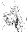
- FIGS. 1-10 show various views of portions of saws that employ example embodiments from different perspectives in order to facilitate description of some example embodiments.
- a tile or masonry saw assembly 100 may include a saw 110 and a frame 120.
- the frame 120 may generally support the saw 110 so that the saw can be moved relative to the frame 120 to execute cutting operations with the saw 110.
- the saw 110 may include a motor 112 that is operable responsive to selective application of power from a power source. Based on the power source employed, the motor 112 may be, for example, either electric powered or gasoline/petrol powered. Accordingly, responsive to application of power to the motor 112, the motor 112 may be configured to power a blade assembly 114 to cut a workpiece that may be, for example, tile, stone, brick, concrete or other such construction materials.
- the operator may at least partially control operation of the saw 110 via a handle 116 that allows a movement assembly 118 of the saw 110 to be employed to move the saw 110 relative to the frame 120.
- the saw 110 may employ wet cutting such that water is applied to the blade assembly 114 via mechanisms described in greater detail below.
- the frame 120 may include a water collection system 121 that operates to collect at least some of the water that is applied to the blade assembly 114.
- the water collection system 121 may include a collector 122 disposed at one end of the frame 120.
- the collector 122 may extend between lateral sides of the frame 120 from one longitudinal end of the frame 120 toward a water tank 124 that is disposed at the opposite longitudinal end of the frame 120.
- the collector 122 and the water tank 124 may combine to form a surface for collecting any water expelled from the blade assembly 114 during operation.
- the collector 122 may generally lie horizontally within the frame 120 and may include sloped sides that direct water from areas near the lateral edges of the collector 122 toward a longitudinal centerline of the frame 120.
- the collector 122 may also be sloped to direct water away from the longitudinal end of the frame 120 to which the collector 122 is proximate toward the water tank 124.
- the water tank 124 may collect the water provided thereto by the collector 122 for reuse in application of water to the blade assembly 114.
- the water collection system 121 of an example embodiment may provide a relatively efficient way to apply, collect and reuse water for wet cutting.
- the frame 120 may also include a workpiece support 126, which may provide a framework for supporting workpieces that are to be cut using the saw 110.
- the workpiece support 126 may be a substantially planar support structure that extends transversely across the frame 120 to hold workpieces being cut.
- the workpiece support 126 may be enabled to slide or roll along the longitudinal length of the frame 120 such that it is supported above either or both of the collector 122 and the water tank 124.
- the workpiece support 126 may include trenches 128 or cutout portions that define recesses in which the cutting element of the blade assembly 114 may rotate when a cutting operation is conducted.
- the trenches 128 may also operate to direct any water that is sprayed therein or otherwise collects therein to either or both of the collector 122 and the water tank 124.
- the movement assembly 118 may include support arms 130 that are bent to form a U or C shape such that one arm of the U or C shape supports the saw 110 and the other arm of the U or C shape movably couples the saw 110 to the frame 120.
- the saw 110 may be pivotally mounted to one of the support arms 130 so that the saw 110 can pivot about a pivot axis 132 that is substantially perpendicular to the longitudinal length of the frame 120.
- torsion springs 134 may be provided to facilitate rotation about the pivot axis 132 so that the operator can pivot the saw 110 with less manual force applied.
- rotation about a tilt axis 140 may also be possible so that the saw 110 may be tilted to achieve angled cuts.
- the saw 110 may include a locking plate 142, which may include an arcuate slot inside which a clamping member may ride and be tightened to lock the saw 110 at a desirable tilt angle following rotation about the tilt axis 140.
- the tilt axis 140 may extend parallel to the longitudinal axis of the frame 120.
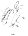
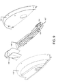
- the blade assembly 114 may include a blade guard 150 that may be formed, in some cases, of two separate members that may form half-shells (e.g., first blade guard member 152 and second blade guard member 154).
- the blade guard 150 may include a rotating splash guard 156 that may be pivotally coupled to the blade guard 150 to direct water toward the water collecting system 121.
- a blade 158 of the saw 110 may be at least partially housed within the blade guard 150.
- the blade guard 150 may leave less than half of the blade 158 exposed and therefore shield only the remaining, unexposed portion.
- the rotating splash guard 156 may be rotatable over a predefined range that may extend over the unexposed portion, but may also enable at least a portion of the exposed portion of the blade 158 to also be covered or surrounded on lateral sides by the rotating splash guard 152.
- Water splashing e.g., responsive to spraying of water onto the blade 158 caused by water being carried in cutouts 155 on the blade 158 may be deflected to the collector 122 by the rotating splash guard 152 or by a tail piece 157 of the rotating splash guard 152.
- the rotating splash guard 156 may be pivotally coupled to the first blade guard member 152 and the second blade guard member 154 via one or more arcuate slots provided in the rotating splash guard 156 to receive a corresponding one or more protrusions that extend from opposing sides of the first blade guard member 152 and the second blade guard member 154.
- the protrusions and/or slots may be configured such that the rotating splash guard 156 can be rotated to a point at which the slots and protrusions are aligned in such a was as to allow the rotating splash guard to be removed without the use of tools.
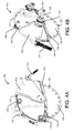
- Water may be provided into the blade guard 150 and collected at a water collector 160 that may be defined by channels 159 that extend along lateral sides of the blade 158.
- the provision of water into the blade guard 150 may be accomplished via one or more control valves, pumps and/or hoses 162 that may supply water to nozzles 164.
- the nozzles 164 may be provided at an opposite end of the blade guard 150 relative to the end over which the rotating splash guard 156 extends.
- the hoses 162 may be mounted or otherwise provided proximate to an outside of the blade guard 150 to route water to the nozzles 164.
- the nozzles 164 may be positioned to extend from outside of the first blade guard member 152 and the second blade guard member 154, through the first blade guard member 152 and the second blade guard member 154 into a portion of the blade guard 150. Moreover, the nozzles 164 may be pointed toward the blade 158 (e.g., at an upward angle relative to an axis of rotation 169 of the blade 158). Water may therefore be provided through the hoses 162 to the nozzles 164 to a location very close to the blade 158 to direct the water onto the blade 158.
- the rotation of the blade 158 about an axle 168 that is turned by a belt pulley 170 operably coupled to the motor 112 and, in some cases, the collection of water in the cutouts 155, may cause a mist to be created to minimize dust distribution when the workpiece is cut.
- the nozzles 164 may be positioned to be proximate to the blade 158 within a distance less than 5 mm, and possibly less than 4 mm from the blade 158.
- the nozzles 164 may also be directed at an angle (e.g., relative to the axis of rotation 169 of the blade 158) that is greater than 15 degrees, or even greater than 30 degrees relative to the axis of rotation 169. In some embodiments, the nozzles 164 may be directed at an angle of about 45 degrees relative to the axis of rotation 169.
- the nozzles 164 are also provided proximate to an end of the water collector 160 that is closest to the operator.
- the water that is misted within the blade guard 150 proximate to the blade 158 may be collected in the channels 159 of the water collector 160.
- a relatively small tolerance may be provided between inner sidewalls of the water collector 160 and the blade 158 to attempt to keep splashing to a minimum.
- the outlet 166 may also be at a lower elevation than the elevation at which the end of the water collector 160 to which the nozzles 164 are proximate.
- a link 151 may be provided on the saw 110 to slightly rotate, pivot or turn the blade guard 150 during execution of a cut, so that the channels 159 are sloped downward toward the outlet 166 while progressing through the cut.
- all water in the water collector 160 may gravity drain out the outlet 166 and into the water collector 122 or water tank 124.
- the water collector 160 may define a blade aperture 170 through which the blade 158 extends.
- the first and second blade guard members 152 and 154 may have a gasket 153 that may be provided at the joint therebetween to maintain the joint waterproof.
- the only place for water injected into the blade guard 150 to go is generally onto the blade 158 (or in the cutouts 155), or into the channels 159 with minimal splashing of water.
- the two portions of the blade guard 150 may be removable from each other so that, for example, the blade 158 can be easily replaced.
- Connection knobs 168 or any other fastener may be employed to facilitate securing the first and second blade guard members 152 and 154 together or taking them apart.
- the first and second blade guard members 152 and 154 may be taken apart, it may also be appreciated that some embodiments may enable the water collector 160 to also be split into two corresponding parts.
- separate channel members e.g., a first channel member 161 and a second channel member 163 may be provided at a bottom of each respective one of the first and second blade guard members 152 and 154.
- the first and second blade guard members 152' and 154' may be separable and may support a rotating splash guard 156' as described above.
- the water collector 160' may be defined as a single, unitary piece removable from the blade guard 150.
- the nozzles 164 may still be positioned closest to the operator and the outlet 166' may be defined at an opposite end (and at a lower elevation) than the nozzles 164.
- the water tank 124 may form a container that can not only collect water for potential reuse, but also allow the water to be transported.
- the water tank 124 may be defined by container walls 180 on six sides.
- a cap 182 may be provided on one of the walls 180 that may be a bottom wall 188 when the water tank 124 is oriented vertically, but may be a side wall when the water tank 124 is oriented horizontally (as would be the case when the water tank 124 is installed in the frame 120).
- the cap 182 may be removed so that water can be filled into the water tank 124.
- the cap 182 may be provided at a recessed portion of the bottom wall 188 so that, in the vertical orientation, the water tank 124 stands on the bottom wall 188 and the cap 182.
- the bottom wall 188 may represent a raised portion relative to a portion of the water tank 124 at which the cap 182 is provided.
- the water tank may also include a handle 184 that is disposed on an opposite side of the water tank 124 relative to the cap 182 so that the water tank 124 may be easily removable from the frame 120 and be easily transportable by hand.
- the handle 184 may be an integral part of the water tank 124.
- a pump housing portion 186 may be provided to house a pump to pump water to the nozzles 164.
- the pump housing portion 186 may have an entrance thereto constructed to filter or otherwise settle out sediments so that the sediments are not likely to enter the pump housing portion 186.
- at least one surface of the water tank 124 e.g., the sidewall 180 that faces upward when the water tank 124 is in the horizontal orientation
- the water tank 124 may be a portion of a water cycle for wet cutting using the saw assembly 100.
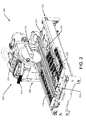
- FIG. 2 is provided to illustrate a tile saw 200 that may employ an example embodiment.
- the tile saw 200 includes many similar components to those described above including, but not limited to, a saw 210 and a frame 220.
- the saw 210 includes a motor 212 similar to the motor 112 described above.
- the saw 210 also includes a blade assembly 214 (which may include a blade guard similar to that described above), a handle 216 and a movement assembly 218. Water may be directed to a water collection system 221 including a collector 222 and a water tank 224 similar to those described above.
- a workpiece support 226 may also be provided, and may include trenches 228 similar to those described above.
- the saw 210 may move longitudinally along one side of the frame 220 via a positioning assembly 300 that includes a series of pulleys, rollers and a flexible coupling member to ride various rails or the like that extend along the frame 220 to enable the movement assembly 118 or 218 to be operably coupled thereto.
- the positioning assembly 300 may therefore allow the saw 110 or 210 to be moved along the rails during or in preparation for engaging in cutting.
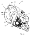
- a hand-held saw 400 may employ some of the structures described above.
- the hand-held saw 400 may include a motor 412 configured to rotatably drive a blade assembly 414 that includes a blade 458.
- the blade 458 may be at least partially housed in a blade guard 450 that is similar to the blade guards described above.
- the blade guard 450 may include a water collector 460 disposed about the open end of the blade guard 450 to provide a relatively small clearance between the blade 458 and the water collector 460.
- the water collector 460 may form channels that extend along the sides of the blade 458 to collect/direct water as described above.
- Hoses 462 may provide water to nozzles 464 that provide or spray the water onto the blade 458 at an upward angle and proximate to cutouts 455 in the blade 458.
- the nozzles 464 may generate water jets to hit the cutouts 555 to form drops or droplets.
- the water drops/droplets are carried with the blade 458 and in the cutouts 455 to reduce dust production during cutting.
- the relatively small clearance between the blade 458 and the collector 460 may facilitate collection of the water that is sprayed on the blade 458 through the nozzles 464 in the water collector 460 for delivery to an outlet disposed at a lower elevation end of the blade guard 450.
- the blade guard and nozzle arrangement described above may also be employed on power cutters, floor saws, road saws, wall saws, floors saws and or the like.
- tracks may be bolted onto a floor or wall, and saws employing example embodiments may be attached to a mobility assembly that runs along the tracks.
- the mobility assembly could include wheels (e.g., at least three wheels) that ride over the ground or any concrete, asphalt or other masonry surface.
- FIG. 12 illustrates an example of a road saw 500 that may have a mobility assembly in addition to the motor 512 that rotatably drives a blade assembly 514.
- the mobility assembly may carry the road saw 500 over a surface 501.
- the motor 512 may be a hydraulic, pneumatic, electric, battery-electric, or internal combustion engine. The latter is used for the shown road saw. For inhouse use an electric motor 512 is often used and the machine is called a floor saw. More generally the machine type is therefore a floor or road saw (500).
- the blade assembly 514 may include a blade 558 that is at least partially enclosed within blade guard 550.
- the blade guard 550 is provided with water via hoses 562 as described above.
- a water collector 560 is provided about the open end of the blade guard 550 to provide a relatively small clearance between the blade 558 and the water collector 560.
- the water provided via hoses 562 is sprayed onto the blade 558 via nozzles 564 disposed on opposite sides of the blade 558 at one end of the water collector 560.
- the nozzles 564 may be provided at a distance less than 5 mm, preferably less than 4 mm, from the blade 558 and may be angled upwardly (relative to the axis of rotation of the blade 558) at an angle of at least 15 degrees and, in some cases, greater than 30 degrees.
- the road saw 500 (or a wall saw) may be enabled to turn in either an upcut direction (shown by the dashed line arrow) or a downcut direction (shown by the solid line arrow).
- an additional set of nozzles 564' may be provided at the opposite end of the water collector 560 relative to the end at which nozzles 564 are provided.
- nozzles 564 and 564' are provided proximate to both ends of the water collector 560.
- the nozzles may be referred to as forward end nozzles 564 and rear end nozzles 564' to facilitate further discussion.
- water valves may be coupled to both the forward end nozzles 564 and the rear end nozzles 564', The water valves may be operable such that water can be directed to either the forward end nozzles 564 or to the rear end nozzles 564'.
- the decision as to which set of nozzles to provide water to may be made based on the direction of rotation of the blade 558.
- water may be provided to both the forward end nozzles 564 or to the rear end nozzles 564' simultaneously. The water is carried with the blade 558 to reduce dust production during cutting.
- the relatively small clearance between the blade 558 and the collector 560 may facilitate collection of the water that is sprayed on the blade 558 through the forward end nozzles 564 or the rear end nozzles 564' in the water collector 560 for delivery to an outlet disposed at a lower elevation end of the blade guard 550.
- a tail piece 580 may be provided to direct water from the water collector 560 onto the ground.
- a hose may also be connected to the tail piece 580 in order to collect the water.
- a wall saw has a very similar blade 558 and blade guard 550 as the road saw of Fig 12 , but it runs along a guiding track that is fixed to a wall or floor. Therefore it is often referred to as a wall or floor saw. Its direction of rotation may be switched, so the same applies as for the road saw described.
- a tile or masonry saw assembly of an example embodiment may include a saw and a frame.
- the saw may include a motor operable to turn a blade of a blade assembly to cut a workpiece.
- the blade assembly is internally wetted during operation by nozzles disposed on opposing sides of the blade to provide water onto the blade within a blade guard configured to shield a portion of the blade.
- the frame is operably coupled to the saw to support the workpiece.
- the frame supports a water collecting system for collecting the water.
- the water collecting system includes a water tank that is removable from the frame.
- the saw assembly of some embodiments may include additional features that may be optionally added either alone or in combination with each other.
- the water tank may further include a pump housing portion configured to interface with a pump to provide water from the water tank to the nozzles.
- the water tank may be configured to lie in a horizontal orientation in the frame, and also be configured to be fillable and provide water to the nozzles while disposed in the frame in the horizontal orientation.
- the water tank may be configured to be fillable while removed from the frame in a vertical orientation so that the water tank has a suitable water level when inserted into the frame in a horizontal orientation.
- any or all of (1) to (3) may be employed in addition to the optional modifications or augmentations described below.
- the pump housing portion may be structured to prevent sediment from entering the pump housing portion.
- the frame may be configured to further support a collector disposed proximate to the water tank to collect water directed away from the blade assembly and provide collected water to the water tank.
- at least one surface of the water tank may be configured to direct water thereon to be collected in the water tank.
- a removable cap may be arranged proximate to a raised portion of a bottom surface of the water tank to enable the water tank to stand vertically when the cap is engaged with the water tank, and to enable the water tank to be emptied of water when the cap is removed.
- a handle may be formed at a portion of the water tank to facilitate mounting or dismounting the water tank from the frame.
- a tile or masonry saw assembly may be provided to include a saw and a frame, which as described above, may include a motor operable to turn a blade of a blade assembly to cut a workpiece.
- the blade assembly is internally wetted during operation by nozzles disposed on opposing sides of the blade to provide water onto the blade within a blade guard configured to shield a portion of the blade.
- the frame is operably coupled to the saw to support the workpiece.
- the frame supports a water collecting system for collecting the water.
- the nozzles are positioned to extend into a portion of the blade guard and to point toward the blade at an upward angle relative to an axis of rotation of the blade.
- the saw assembly of some embodiments may include additional features that may be optionally added either alone or in combination with each other.
- the saw may further include a water collector coupled to the blade guard.
- the water collector may also define a blade aperture through which the blade extends.
- the nozzles may be provided proximate to a first end of the water collector that is closest to an operator, and the water collector may direct the water through channels to an outlet disposed at a second end of the water collector (160).
- the water collector may be defined as a single, unitary piece removable from the blade guard.
- the water collector may be defined by separate channel members.
- the separate channel members may be integrated into respective ones of a first blade guard member and a second blade guard member that form the blade guard.
- the blade may include cutouts reaching inwardly from a perimeter of the blade.
- the nozzles may be arranged so that the jets from the nozzles hit the cutouts to form a mist.
- the nozzles may be arranged at a distance less than 5 mm, preferably less than 4 mm, from the blade.
- the nozzles may be directed at an angle greater than 15 degrees, preferably greater than 30 degrees relative to the axis of rotation. In some cases, the angle may be about 45 degrees.
- the saw assembly may further include a rotating splash guard pivotally coupled to the blade guard to direct water toward the water collecting system from the outlet.
- the blade guard may be rotatably arranged around the axis of rotation and a link may be arranged to turn the blade guard during the cut, so that the channels in the water collector slope downward from the first end to the second end with the outlet during the cut.
- the water collector may be disposed on the blade guard such that the nozzles are at a higher elevation than the outlet. Additionally or alternatively, at least some water dispensed into the blade guard may be carried to the workpiece, and excess water may be directed to the water collector by the blade and the blade guard.
Landscapes
- Engineering & Computer Science (AREA)
- Mechanical Engineering (AREA)
- Mining & Mineral Resources (AREA)
- Processing Of Stones Or Stones Resemblance Materials (AREA)
Applications Claiming Priority (1)
| Application Number | Priority Date | Filing Date | Title |
|---|---|---|---|
| SE1450761 | 2014-06-18 |
Publications (3)
| Publication Number | Publication Date |
|---|---|
| EP2965886A2 true EP2965886A2 (fr) | 2016-01-13 |
| EP2965886A3 EP2965886A3 (fr) | 2016-04-20 |
| EP2965886B1 EP2965886B1 (fr) | 2020-12-02 |
Family
ID=53039368
Family Applications (1)
| Application Number | Title | Priority Date | Filing Date |
|---|---|---|---|
| EP15446501.7A Active EP2965886B1 (fr) | 2014-06-18 | 2015-04-14 | Carreau ou ensemble scie de maçonnerie présentant une capacité améliorée de mouillage de lame |
Country Status (3)
| Country | Link |
|---|---|
| US (2) | US9630343B2 (fr) |
| EP (1) | EP2965886B1 (fr) |
| AU (1) | AU2015202833B2 (fr) |
Cited By (2)
| Publication number | Priority date | Publication date | Assignee | Title |
|---|---|---|---|---|
| WO2018084784A1 (fr) * | 2016-11-03 | 2018-05-11 | Husqvarna Ab | Agencement d'élimination de poussière pour un outil entraîné par moteur |
| WO2018147776A1 (fr) * | 2017-02-13 | 2018-08-16 | Husqvarna Ab | Agencement de collecte de poussière de scie à carreau ou de maçonnerie |
Families Citing this family (21)
| Publication number | Priority date | Publication date | Assignee | Title |
|---|---|---|---|---|
| US9430909B2 (en) | 2014-04-08 | 2016-08-30 | Micro-Gaming Ventures, LLC | Location-based wagering via remote devices |
| CN104339459B (zh) * | 2013-08-02 | 2016-08-10 | 南京德朔实业有限公司 | 台型切割机 |
| US11783679B2 (en) | 2014-04-08 | 2023-10-10 | Micro-Gaming Ventures, LLC | Location-based wagering via remote devices |
| US10994444B2 (en) * | 2015-08-17 | 2021-05-04 | Chao-Ying LEE | Power saw blade cooling arrangement |
| US9962858B2 (en) * | 2015-11-02 | 2018-05-08 | Chin-Chin Chang | Ceramic and masonry power saw |
| US10603819B2 (en) * | 2015-12-16 | 2020-03-31 | Black & Decker Inc. | Tile saw |
| ES2630366B1 (es) * | 2016-02-17 | 2018-06-08 | Germans Boada, S.A. | Tapa de protección con refrigeración para discos de cortadoras |
| TWI621513B (zh) * | 2016-03-18 | 2018-04-21 | 力山工業股份有限公司 | 磁磚切割機之收納式擋水裝置 |
| CA3082210A1 (fr) * | 2016-11-16 | 2018-05-24 | Envirochasing Ip Holdings Pty Ltd | Appareil d'extraction |
| US10252444B2 (en) | 2017-04-14 | 2019-04-09 | Tti (Macao Commercial Offshore) Limited | Tile saw |
| US12539550B2 (en) * | 2018-02-11 | 2026-02-03 | Chao-Ying LEE | Method and system of rivering filtration for power saw machine |
| US10857604B2 (en) * | 2018-02-11 | 2020-12-08 | Chao-Ying LEE | Method and system of rivering filtration for power saw machine |
| US10857688B2 (en) * | 2018-02-11 | 2020-12-08 | Chao-Ying LEE | Method and system of rivering filtration for power saw machine |
| FR3082855B1 (fr) * | 2018-06-22 | 2021-03-12 | Soc Des Anciens Etablissements L Geismar | Systeme de machine-outil, notamment pour des travaux sur une voie de chemin ferre |
| CN109591203A (zh) * | 2018-12-11 | 2019-04-09 | 夏平 | 一种防尘切割机 |
| WO2021102828A1 (fr) * | 2019-11-28 | 2021-06-03 | 张佩嫦 | Dispositif de coupe de barre d'acier pour construction de bâtiment |
| CN111497039A (zh) * | 2020-04-14 | 2020-08-07 | 黄�益 | 一种泡沫水泥轻质土防粉化切砖机构 |
| US20220178254A1 (en) * | 2020-12-07 | 2022-06-09 | Nanjing Chervon Industry Co., Ltd | Cutting device |
| TWI776490B (zh) * | 2021-05-03 | 2022-09-01 | 力山工業股份有限公司 | 用於磁磚切割機之集水裝置 |
| CN114872208B (zh) * | 2022-05-12 | 2024-03-12 | 广东博智林机器人有限公司 | 集中裁砖机器人及集中裁砖加工线 |
| US12528174B2 (en) * | 2023-09-01 | 2026-01-20 | Hydro-Tail Llc | Universal attachable water directing device for power tools |
Family Cites Families (28)
| Publication number | Priority date | Publication date | Assignee | Title |
|---|---|---|---|---|
| US3765724A (en) * | 1971-03-01 | 1973-10-16 | C Hatcher | Pavement cutting machine with tractor-trailer assembly |
| US3848929A (en) * | 1973-06-14 | 1974-11-19 | Engelhard Min & Chem | Water applicator for a pavement grooving machine |
| US4428159A (en) | 1981-07-29 | 1984-01-31 | Sigetich John D | Portable, direct drive abrasive saw |
| US4414783A (en) * | 1981-08-19 | 1983-11-15 | Buehler Ltd. | Coolant system for rotating blade cutter |
| US4998775A (en) * | 1989-10-10 | 1991-03-12 | Hollifield David L | Apparatus for precision cutting of concrete surfaces |
| US5477844A (en) * | 1993-11-10 | 1995-12-26 | Diamant Boart, Inc. | Slurry recovery system for a wet cutting saw |
| DE19545416A1 (de) | 1995-12-06 | 1997-06-12 | Stihl Maschf Andreas | Düse zur Flüssigkeitszufuhr zu einem drehenden Werkzeug |
| US5676124A (en) | 1996-01-11 | 1997-10-14 | K Diamond Inc. | Ceramic and masonry power saw |
| US6000387A (en) * | 1998-04-20 | 1999-12-14 | Lee; Wy Peron | Power saw with fluid cooling bearing assembly |
| IT1300015B1 (it) | 1998-05-07 | 2000-04-04 | Skc Di Tondini Claudio | Copridisco per taglierina elettrica con raffreddamento del disco ad acqua. |
| IL125469A (en) * | 1998-07-23 | 2001-07-24 | Sherez Shaul | Hand held cutting tool |
| US6283110B1 (en) | 1999-01-12 | 2001-09-04 | Wy Peron Lee | Cutting saw machine |
| US6318351B1 (en) * | 1999-09-17 | 2001-11-20 | Bioart Longyear Company | Waste containment system for an abrading or cutting device |
| US6439218B1 (en) | 2000-06-01 | 2002-08-27 | Mk Diamond Products, Inc. | Cutting apparatus with a supporting table |
| US6916236B2 (en) * | 2001-06-13 | 2005-07-12 | Terpstra Enterprises Pty Ltd. | Extraction apparatus |
| US8286539B2 (en) * | 2002-11-01 | 2012-10-16 | Black & Decker Inc. | Tile saw |
| CN2593987Y (zh) | 2003-01-21 | 2003-12-24 | 黄天义 | 环保型高压水切式超薄多片锯 |
| US6932073B2 (en) | 2003-07-23 | 2005-08-23 | Charlie Zhang | Power tool work table |
| DE102005002126A1 (de) * | 2005-01-17 | 2006-07-20 | Andreas Stihl Ag & Co. Kg | Wasserversorgung eines handgeführten Arbeitsgerätes |
| US7987752B2 (en) * | 2008-03-18 | 2011-08-02 | Mk Diamond Products, Inc. | System and method for delivering pressurized fluid to a rotary cutting blade |
| WO2009143567A1 (fr) | 2008-05-30 | 2009-12-03 | Robert Andrew Irvine | Scie de découpe humide |
| US7967391B1 (en) * | 2008-08-05 | 2011-06-28 | Dalley Brandon J | Saw and water combination system |
| US11040464B2 (en) * | 2009-03-17 | 2021-06-22 | Husqvarna Ab | Cutting machine with a liquid lubrication delivery system having a controlled liquid level |
| CN201659635U (zh) * | 2010-03-26 | 2010-12-01 | 南京搏峰电动工具有限公司 | 石材切割机 |
| JP2012040622A (ja) * | 2010-08-16 | 2012-03-01 | Shoichi Shibuya | 切断装置及び切断方法 |
| CN102756167B (zh) | 2011-04-27 | 2014-01-22 | 承澔科技股份有限公司 | 切割机刀具护盖的掀盖装置 |
| DE202011050396U1 (de) | 2011-06-08 | 2012-09-10 | Makita Corporation | Zuführeinrichtung zur Bedüsung eines Werkzeugs eines handhaltbaren Motorarbeitsgerätes und ebensolches Motorarbeitsgerät |
| DE102012221273A1 (de) | 2012-11-21 | 2014-05-22 | Hilti Aktiengesellschaft | Werkzeuggerät mit einer Sprühvorrichtung zur Staubbindung |
-
2015
- 2015-04-14 EP EP15446501.7A patent/EP2965886B1/fr active Active
- 2015-05-26 AU AU2015202833A patent/AU2015202833B2/en not_active Ceased
- 2015-06-18 US US14/742,924 patent/US9630343B2/en active Active
-
2017
- 2017-03-16 US US15/460,759 patent/US9975273B2/en active Active
Non-Patent Citations (1)
| Title |
|---|
| None |
Cited By (5)
| Publication number | Priority date | Publication date | Assignee | Title |
|---|---|---|---|---|
| WO2018084784A1 (fr) * | 2016-11-03 | 2018-05-11 | Husqvarna Ab | Agencement d'élimination de poussière pour un outil entraîné par moteur |
| US11059114B2 (en) | 2016-11-03 | 2021-07-13 | Husqvarna Ab | Dust removal arrangement for an engine-driven tool |
| US11400531B2 (en) | 2016-11-03 | 2022-08-02 | Husqvarna Ab | Dust removal arrangement for an engine-driven tool |
| WO2018147776A1 (fr) * | 2017-02-13 | 2018-08-16 | Husqvarna Ab | Agencement de collecte de poussière de scie à carreau ou de maçonnerie |
| US11498243B2 (en) | 2017-02-13 | 2022-11-15 | Husqvarna Ab | Tile or masonry saw dust collection arrangement |
Also Published As
| Publication number | Publication date |
|---|---|
| AU2015202833A1 (en) | 2016-01-21 |
| US9630343B2 (en) | 2017-04-25 |
| US20150367530A1 (en) | 2015-12-24 |
| US20170182677A1 (en) | 2017-06-29 |
| EP2965886A3 (fr) | 2016-04-20 |
| EP2965886B1 (fr) | 2020-12-02 |
| US9975273B2 (en) | 2018-05-22 |
| AU2015202833B2 (en) | 2016-08-04 |
Similar Documents
| Publication | Publication Date | Title |
|---|---|---|
| US9975273B2 (en) | Tile or masonry saw assembly with improved blade wetting capability | |
| KR101567200B1 (ko) | 건식 집진유닛을 구비하는 보도블록 절단장치 | |
| EP2965885B1 (fr) | Ensemble scie de maçonnerie ou de carreaux avec double mouvement | |
| US5564408A (en) | Pavement treatment method and apparatus | |
| KR101547834B1 (ko) | 3단 분리형 콘크리트 건식 컷팅기 | |
| JP2006516227A (ja) | 舗装処理装置のための流体収集アセンブリおよびブレードガード | |
| US4779603A (en) | Brick saw container | |
| AU779637B2 (en) | Waste containment system and method for an abrading or cutting device | |
| CN104985703A (zh) | 刀片护罩组件、防溅罩组件及切割组件和加工机器 | |
| US20140261367A1 (en) | Portable tile saw | |
| KR101984012B1 (ko) | 로봇 청소기 | |
| KR101080868B1 (ko) | 친환경 콘크리트 포장도로 실링재 제거 장치 | |
| US8347871B2 (en) | Wet cutting saw | |
| KR100974612B1 (ko) | 도로 커팅기 | |
| EP3214989B1 (fr) | Appareil pour le traitement de surfaces avec un piège d'eau integré pour collecter déchet résiduel | |
| CN106192833B (zh) | 一种扫刷装置和电动地面清扫机 | |
| KR20170051452A (ko) | 습식 절삭톱 | |
| JP7367126B2 (ja) | 路面切断装置及び路面切断方法 | |
| KR101483778B1 (ko) | 절삭형 노면요철 포장기 및 절삭형 노면요철 포장 방법 | |
| KR101537218B1 (ko) | 도로 절단장치 | |
| KR101857849B1 (ko) | 회전식 날 연마장치 | |
| KR100708627B1 (ko) | 회전식 지면 평삭기 | |
| US7578885B2 (en) | Concrete/asphalt wet washing system | |
| JP3255345U (ja) | 切断機 | |
| KR102896030B1 (ko) | 스키드 로더 장착형 연삭장치 |
Legal Events
| Date | Code | Title | Description |
|---|---|---|---|
| PUAI | Public reference made under article 153(3) epc to a published international application that has entered the european phase |
Free format text: ORIGINAL CODE: 0009012 |
|
| AK | Designated contracting states |
Kind code of ref document: A2 Designated state(s): AL AT BE BG CH CY CZ DE DK EE ES FI FR GB GR HR HU IE IS IT LI LT LU LV MC MK MT NL NO PL PT RO RS SE SI SK SM TR |
|
| AX | Request for extension of the european patent |
Extension state: BA ME |
|
| PUAL | Search report despatched |
Free format text: ORIGINAL CODE: 0009013 |
|
| AK | Designated contracting states |
Kind code of ref document: A3 Designated state(s): AL AT BE BG CH CY CZ DE DK EE ES FI FR GB GR HR HU IE IS IT LI LT LU LV MC MK MT NL NO PL PT RO RS SE SI SK SM TR |
|
| AX | Request for extension of the european patent |
Extension state: BA ME |
|
| RIC1 | Information provided on ipc code assigned before grant |
Ipc: B28D 1/04 20060101ALI20160315BHEP Ipc: B28D 7/02 20060101AFI20160315BHEP Ipc: B23D 59/02 20060101ALI20160315BHEP |
|
| 17P | Request for examination filed |
Effective date: 20161017 |
|
| RBV | Designated contracting states (corrected) |
Designated state(s): AL AT BE BG CH CY CZ DE DK EE ES FI FR GB GR HR HU IE IS IT LI LT LU LV MC MK MT NL NO PL PT RO RS SE SI SK SM TR |
|
| GRAP | Despatch of communication of intention to grant a patent |
Free format text: ORIGINAL CODE: EPIDOSNIGR1 |
|
| STAA | Information on the status of an ep patent application or granted ep patent |
Free format text: STATUS: GRANT OF PATENT IS INTENDED |
|
| INTG | Intention to grant announced |
Effective date: 20200630 |
|
| GRAS | Grant fee paid |
Free format text: ORIGINAL CODE: EPIDOSNIGR3 |
|
| GRAA | (expected) grant |
Free format text: ORIGINAL CODE: 0009210 |
|
| STAA | Information on the status of an ep patent application or granted ep patent |
Free format text: STATUS: THE PATENT HAS BEEN GRANTED |
|
| AK | Designated contracting states |
Kind code of ref document: B1 Designated state(s): AL AT BE BG CH CY CZ DE DK EE ES FI FR GB GR HR HU IE IS IT LI LT LU LV MC MK MT NL NO PL PT RO RS SE SI SK SM TR |
|
| REG | Reference to a national code |
Ref country code: GB Ref legal event code: FG4D |
|
| REG | Reference to a national code |
Ref country code: AT Ref legal event code: REF Ref document number: 1340408 Country of ref document: AT Kind code of ref document: T Effective date: 20201215 Ref country code: CH Ref legal event code: EP |
|
| REG | Reference to a national code |
Ref country code: IE Ref legal event code: FG4D |
|
| REG | Reference to a national code |
Ref country code: DE Ref legal event code: R096 Ref document number: 602015062836 Country of ref document: DE |
|
| PG25 | Lapsed in a contracting state [announced via postgrant information from national office to epo] |
Ref country code: FI Free format text: LAPSE BECAUSE OF FAILURE TO SUBMIT A TRANSLATION OF THE DESCRIPTION OR TO PAY THE FEE WITHIN THE PRESCRIBED TIME-LIMIT Effective date: 20201202 Ref country code: RS Free format text: LAPSE BECAUSE OF FAILURE TO SUBMIT A TRANSLATION OF THE DESCRIPTION OR TO PAY THE FEE WITHIN THE PRESCRIBED TIME-LIMIT Effective date: 20201202 Ref country code: NO Free format text: LAPSE BECAUSE OF FAILURE TO SUBMIT A TRANSLATION OF THE DESCRIPTION OR TO PAY THE FEE WITHIN THE PRESCRIBED TIME-LIMIT Effective date: 20210302 Ref country code: GR Free format text: LAPSE BECAUSE OF FAILURE TO SUBMIT A TRANSLATION OF THE DESCRIPTION OR TO PAY THE FEE WITHIN THE PRESCRIBED TIME-LIMIT Effective date: 20210303 |
|
| REG | Reference to a national code |
Ref country code: NL Ref legal event code: MP Effective date: 20201202 |
|
| REG | Reference to a national code |
Ref country code: AT Ref legal event code: MK05 Ref document number: 1340408 Country of ref document: AT Kind code of ref document: T Effective date: 20201202 |
|
| PG25 | Lapsed in a contracting state [announced via postgrant information from national office to epo] |
Ref country code: SE Free format text: LAPSE BECAUSE OF FAILURE TO SUBMIT A TRANSLATION OF THE DESCRIPTION OR TO PAY THE FEE WITHIN THE PRESCRIBED TIME-LIMIT Effective date: 20201202 Ref country code: LV Free format text: LAPSE BECAUSE OF FAILURE TO SUBMIT A TRANSLATION OF THE DESCRIPTION OR TO PAY THE FEE WITHIN THE PRESCRIBED TIME-LIMIT Effective date: 20201202 Ref country code: PL Free format text: LAPSE BECAUSE OF FAILURE TO SUBMIT A TRANSLATION OF THE DESCRIPTION OR TO PAY THE FEE WITHIN THE PRESCRIBED TIME-LIMIT Effective date: 20201202 Ref country code: BG Free format text: LAPSE BECAUSE OF FAILURE TO SUBMIT A TRANSLATION OF THE DESCRIPTION OR TO PAY THE FEE WITHIN THE PRESCRIBED TIME-LIMIT Effective date: 20210302 |
|
| PG25 | Lapsed in a contracting state [announced via postgrant information from national office to epo] |
Ref country code: HR Free format text: LAPSE BECAUSE OF FAILURE TO SUBMIT A TRANSLATION OF THE DESCRIPTION OR TO PAY THE FEE WITHIN THE PRESCRIBED TIME-LIMIT Effective date: 20201202 Ref country code: NL Free format text: LAPSE BECAUSE OF FAILURE TO SUBMIT A TRANSLATION OF THE DESCRIPTION OR TO PAY THE FEE WITHIN THE PRESCRIBED TIME-LIMIT Effective date: 20201202 |
|
| REG | Reference to a national code |
Ref country code: LT Ref legal event code: MG9D |
|
| PG25 | Lapsed in a contracting state [announced via postgrant information from national office to epo] |
Ref country code: LT Free format text: LAPSE BECAUSE OF FAILURE TO SUBMIT A TRANSLATION OF THE DESCRIPTION OR TO PAY THE FEE WITHIN THE PRESCRIBED TIME-LIMIT Effective date: 20201202 Ref country code: PT Free format text: LAPSE BECAUSE OF FAILURE TO SUBMIT A TRANSLATION OF THE DESCRIPTION OR TO PAY THE FEE WITHIN THE PRESCRIBED TIME-LIMIT Effective date: 20210405 Ref country code: RO Free format text: LAPSE BECAUSE OF FAILURE TO SUBMIT A TRANSLATION OF THE DESCRIPTION OR TO PAY THE FEE WITHIN THE PRESCRIBED TIME-LIMIT Effective date: 20201202 Ref country code: SK Free format text: LAPSE BECAUSE OF FAILURE TO SUBMIT A TRANSLATION OF THE DESCRIPTION OR TO PAY THE FEE WITHIN THE PRESCRIBED TIME-LIMIT Effective date: 20201202 Ref country code: SM Free format text: LAPSE BECAUSE OF FAILURE TO SUBMIT A TRANSLATION OF THE DESCRIPTION OR TO PAY THE FEE WITHIN THE PRESCRIBED TIME-LIMIT Effective date: 20201202 Ref country code: EE Free format text: LAPSE BECAUSE OF FAILURE TO SUBMIT A TRANSLATION OF THE DESCRIPTION OR TO PAY THE FEE WITHIN THE PRESCRIBED TIME-LIMIT Effective date: 20201202 Ref country code: CZ Free format text: LAPSE BECAUSE OF FAILURE TO SUBMIT A TRANSLATION OF THE DESCRIPTION OR TO PAY THE FEE WITHIN THE PRESCRIBED TIME-LIMIT Effective date: 20201202 |
|
| PG25 | Lapsed in a contracting state [announced via postgrant information from national office to epo] |
Ref country code: AT Free format text: LAPSE BECAUSE OF FAILURE TO SUBMIT A TRANSLATION OF THE DESCRIPTION OR TO PAY THE FEE WITHIN THE PRESCRIBED TIME-LIMIT Effective date: 20201202 |
|
| REG | Reference to a national code |
Ref country code: DE Ref legal event code: R097 Ref document number: 602015062836 Country of ref document: DE |
|
| PG25 | Lapsed in a contracting state [announced via postgrant information from national office to epo] |
Ref country code: IS Free format text: LAPSE BECAUSE OF FAILURE TO SUBMIT A TRANSLATION OF THE DESCRIPTION OR TO PAY THE FEE WITHIN THE PRESCRIBED TIME-LIMIT Effective date: 20210402 |
|
| PLBE | No opposition filed within time limit |
Free format text: ORIGINAL CODE: 0009261 |
|
| STAA | Information on the status of an ep patent application or granted ep patent |
Free format text: STATUS: NO OPPOSITION FILED WITHIN TIME LIMIT |
|
| PG25 | Lapsed in a contracting state [announced via postgrant information from national office to epo] |
Ref country code: IT Free format text: LAPSE BECAUSE OF FAILURE TO SUBMIT A TRANSLATION OF THE DESCRIPTION OR TO PAY THE FEE WITHIN THE PRESCRIBED TIME-LIMIT Effective date: 20201202 Ref country code: AL Free format text: LAPSE BECAUSE OF FAILURE TO SUBMIT A TRANSLATION OF THE DESCRIPTION OR TO PAY THE FEE WITHIN THE PRESCRIBED TIME-LIMIT Effective date: 20201202 |
|
| 26N | No opposition filed |
Effective date: 20210903 |
|
| PG25 | Lapsed in a contracting state [announced via postgrant information from national office to epo] |
Ref country code: SI Free format text: LAPSE BECAUSE OF FAILURE TO SUBMIT A TRANSLATION OF THE DESCRIPTION OR TO PAY THE FEE WITHIN THE PRESCRIBED TIME-LIMIT Effective date: 20201202 Ref country code: DK Free format text: LAPSE BECAUSE OF FAILURE TO SUBMIT A TRANSLATION OF THE DESCRIPTION OR TO PAY THE FEE WITHIN THE PRESCRIBED TIME-LIMIT Effective date: 20201202 Ref country code: ES Free format text: LAPSE BECAUSE OF FAILURE TO SUBMIT A TRANSLATION OF THE DESCRIPTION OR TO PAY THE FEE WITHIN THE PRESCRIBED TIME-LIMIT Effective date: 20201202 Ref country code: MC Free format text: LAPSE BECAUSE OF FAILURE TO SUBMIT A TRANSLATION OF THE DESCRIPTION OR TO PAY THE FEE WITHIN THE PRESCRIBED TIME-LIMIT Effective date: 20201202 |
|
| PG25 | Lapsed in a contracting state [announced via postgrant information from national office to epo] |
Ref country code: LU Free format text: LAPSE BECAUSE OF NON-PAYMENT OF DUE FEES Effective date: 20210414 |
|
| REG | Reference to a national code |
Ref country code: BE Ref legal event code: MM Effective date: 20210430 |
|
| PG25 | Lapsed in a contracting state [announced via postgrant information from national office to epo] |
Ref country code: LI Free format text: LAPSE BECAUSE OF NON-PAYMENT OF DUE FEES Effective date: 20210430 Ref country code: CH Free format text: LAPSE BECAUSE OF NON-PAYMENT OF DUE FEES Effective date: 20210430 |
|
| PG25 | Lapsed in a contracting state [announced via postgrant information from national office to epo] |
Ref country code: IE Free format text: LAPSE BECAUSE OF NON-PAYMENT OF DUE FEES Effective date: 20210414 |
|
| PG25 | Lapsed in a contracting state [announced via postgrant information from national office to epo] |
Ref country code: IS Free format text: LAPSE BECAUSE OF FAILURE TO SUBMIT A TRANSLATION OF THE DESCRIPTION OR TO PAY THE FEE WITHIN THE PRESCRIBED TIME-LIMIT Effective date: 20210402 |
|
| PG25 | Lapsed in a contracting state [announced via postgrant information from national office to epo] |
Ref country code: BE Free format text: LAPSE BECAUSE OF NON-PAYMENT OF DUE FEES Effective date: 20210430 |
|
| PGFP | Annual fee paid to national office [announced via postgrant information from national office to epo] |
Ref country code: FR Payment date: 20230309 Year of fee payment: 9 |
|
| PG25 | Lapsed in a contracting state [announced via postgrant information from national office to epo] |
Ref country code: HU Free format text: LAPSE BECAUSE OF FAILURE TO SUBMIT A TRANSLATION OF THE DESCRIPTION OR TO PAY THE FEE WITHIN THE PRESCRIBED TIME-LIMIT; INVALID AB INITIO Effective date: 20150414 |
|
| P01 | Opt-out of the competence of the unified patent court (upc) registered |
Effective date: 20230419 |
|
| PG25 | Lapsed in a contracting state [announced via postgrant information from national office to epo] |
Ref country code: CY Free format text: LAPSE BECAUSE OF FAILURE TO SUBMIT A TRANSLATION OF THE DESCRIPTION OR TO PAY THE FEE WITHIN THE PRESCRIBED TIME-LIMIT Effective date: 20201202 |
|
| PG25 | Lapsed in a contracting state [announced via postgrant information from national office to epo] |
Ref country code: MK Free format text: LAPSE BECAUSE OF FAILURE TO SUBMIT A TRANSLATION OF THE DESCRIPTION OR TO PAY THE FEE WITHIN THE PRESCRIBED TIME-LIMIT Effective date: 20201202 |
|
| PG25 | Lapsed in a contracting state [announced via postgrant information from national office to epo] |
Ref country code: TR Free format text: LAPSE BECAUSE OF FAILURE TO SUBMIT A TRANSLATION OF THE DESCRIPTION OR TO PAY THE FEE WITHIN THE PRESCRIBED TIME-LIMIT Effective date: 20201202 |
|
| PG25 | Lapsed in a contracting state [announced via postgrant information from national office to epo] |
Ref country code: MT Free format text: LAPSE BECAUSE OF FAILURE TO SUBMIT A TRANSLATION OF THE DESCRIPTION OR TO PAY THE FEE WITHIN THE PRESCRIBED TIME-LIMIT Effective date: 20201202 |
|
| PG25 | Lapsed in a contracting state [announced via postgrant information from national office to epo] |
Ref country code: FR Free format text: LAPSE BECAUSE OF NON-PAYMENT OF DUE FEES Effective date: 20240430 |
|
| PG25 | Lapsed in a contracting state [announced via postgrant information from national office to epo] |
Ref country code: FR Free format text: LAPSE BECAUSE OF NON-PAYMENT OF DUE FEES Effective date: 20240430 |
|
| PGFP | Annual fee paid to national office [announced via postgrant information from national office to epo] |
Ref country code: GB Payment date: 20250312 Year of fee payment: 11 |
|
| PGFP | Annual fee paid to national office [announced via postgrant information from national office to epo] |
Ref country code: DE Payment date: 20250313 Year of fee payment: 11 |