EP2965941B1 - Partie primaire pour un appareil de chargement inductif - Google Patents
Partie primaire pour un appareil de chargement inductif Download PDFInfo
- Publication number
- EP2965941B1 EP2965941B1 EP14176348.2A EP14176348A EP2965941B1 EP 2965941 B1 EP2965941 B1 EP 2965941B1 EP 14176348 A EP14176348 A EP 14176348A EP 2965941 B1 EP2965941 B1 EP 2965941B1
- Authority
- EP
- European Patent Office
- Prior art keywords
- primary
- primary section
- chimney
- coil
- section according
- Prior art date
- Legal status (The legal status is an assumption and is not a legal conclusion. Google has not performed a legal analysis and makes no representation as to the accuracy of the status listed.)
- Active
Links
Images


Classifications
-
- H—ELECTRICITY
- H02—GENERATION; CONVERSION OR DISTRIBUTION OF ELECTRIC POWER
- H02J—ELECTRIC POWER NETWORKS; CIRCUIT ARRANGEMENTS OR SYSTEMS FOR SUPPLYING OR DISTRIBUTING ELECTRIC POWER; SYSTEMS FOR STORING ELECTRIC ENERGY
- H02J50/00—Circuit arrangements or systems for wireless supply or distribution of electric power
- H02J50/10—Circuit arrangements or systems for wireless supply or distribution of electric power using inductive coupling
-
- B—PERFORMING OPERATIONS; TRANSPORTING
- B60—VEHICLES IN GENERAL
- B60L—PROPULSION OF ELECTRICALLY-PROPELLED VEHICLES; SUPPLYING ELECTRIC POWER FOR AUXILIARY EQUIPMENT OF ELECTRICALLY-PROPELLED VEHICLES; ELECTRODYNAMIC BRAKE SYSTEMS FOR VEHICLES IN GENERAL; MAGNETIC SUSPENSION OR LEVITATION FOR VEHICLES; MONITORING OPERATING VARIABLES OF ELECTRICALLY-PROPELLED VEHICLES; ELECTRIC SAFETY DEVICES FOR ELECTRICALLY-PROPELLED VEHICLES
- B60L53/00—Methods of charging batteries, specially adapted for electric vehicles; Charging stations or on-board charging equipment therefor; Exchange of energy storage elements in electric vehicles
- B60L53/10—Methods of charging batteries, specially adapted for electric vehicles; Charging stations or on-board charging equipment therefor; Exchange of energy storage elements in electric vehicles characterised by the energy transfer between the charging station and the vehicle
- B60L53/12—Inductive energy transfer
- B60L53/126—Methods for pairing a vehicle and a charging station, e.g. establishing a one-to-one relation between a wireless power transmitter and a wireless power receiver
-
- H—ELECTRICITY
- H01—ELECTRIC ELEMENTS
- H01F—MAGNETS; INDUCTANCES; TRANSFORMERS; SELECTION OF MATERIALS FOR THEIR MAGNETIC PROPERTIES
- H01F38/00—Adaptations of transformers or inductances for specific applications or functions
- H01F38/14—Inductive couplings
-
- Y—GENERAL TAGGING OF NEW TECHNOLOGICAL DEVELOPMENTS; GENERAL TAGGING OF CROSS-SECTIONAL TECHNOLOGIES SPANNING OVER SEVERAL SECTIONS OF THE IPC; TECHNICAL SUBJECTS COVERED BY FORMER USPC CROSS-REFERENCE ART COLLECTIONS [XRACs] AND DIGESTS
- Y02—TECHNOLOGIES OR APPLICATIONS FOR MITIGATION OR ADAPTATION AGAINST CLIMATE CHANGE
- Y02T—CLIMATE CHANGE MITIGATION TECHNOLOGIES RELATED TO TRANSPORTATION
- Y02T10/00—Road transport of goods or passengers
- Y02T10/60—Other road transportation technologies with climate change mitigation effect
- Y02T10/70—Energy storage systems for electromobility, e.g. batteries
-
- Y—GENERAL TAGGING OF NEW TECHNOLOGICAL DEVELOPMENTS; GENERAL TAGGING OF CROSS-SECTIONAL TECHNOLOGIES SPANNING OVER SEVERAL SECTIONS OF THE IPC; TECHNICAL SUBJECTS COVERED BY FORMER USPC CROSS-REFERENCE ART COLLECTIONS [XRACs] AND DIGESTS
- Y02—TECHNOLOGIES OR APPLICATIONS FOR MITIGATION OR ADAPTATION AGAINST CLIMATE CHANGE
- Y02T—CLIMATE CHANGE MITIGATION TECHNOLOGIES RELATED TO TRANSPORTATION
- Y02T10/00—Road transport of goods or passengers
- Y02T10/60—Other road transportation technologies with climate change mitigation effect
- Y02T10/7072—Electromobility specific charging systems or methods for batteries, ultracapacitors, supercapacitors or double-layer capacitors
-
- Y—GENERAL TAGGING OF NEW TECHNOLOGICAL DEVELOPMENTS; GENERAL TAGGING OF CROSS-SECTIONAL TECHNOLOGIES SPANNING OVER SEVERAL SECTIONS OF THE IPC; TECHNICAL SUBJECTS COVERED BY FORMER USPC CROSS-REFERENCE ART COLLECTIONS [XRACs] AND DIGESTS
- Y02—TECHNOLOGIES OR APPLICATIONS FOR MITIGATION OR ADAPTATION AGAINST CLIMATE CHANGE
- Y02T—CLIMATE CHANGE MITIGATION TECHNOLOGIES RELATED TO TRANSPORTATION
- Y02T90/00—Enabling technologies or technologies with a potential or indirect contribution to GHG emissions mitigation
- Y02T90/10—Technologies relating to charging of electric vehicles
- Y02T90/14—Plug-in electric vehicles
Definitions
- the invention relates to a primary part of a charger, in particular for the inductive transmission of energy from a primary coil of the primary part to a secondary coil of an at least partially electrically operated vehicle, according to the preamble of claim 1, and a charger with such a primary part.
- devices for inductive transmission of electrical energy from a primary coil to a secondary coil are known.
- the secondary coil is located on or in the electric vehicle, while the primary coil is arranged outside the electric vehicle.
- the DE 102011089339 A1 such a device disclosed.
- the device comprises a base element at the bottom of the electric vehicle, a secondary coil associated with the base element, which can be energetically coupled to a storage for electric energy, at least a part of the secondary coil, in particular of the coil core, being movably mounted relative to the base element.
- the device further includes an actuator for relative movement of the spool core of the secondary coil between a lower and an upper position in the z-direction by means of servomotor or manually.
- an actuator for relative movement of the spool core of the secondary coil between a lower and an upper position in the z-direction by means of servomotor or manually.
- the lower position the lower edge of the coil core of the secondary coil is close to a road surface or the like in the roadway, a movable primary coil is arranged. This is intended to achieve an adaptive positioning of the secondary coil to the primary coil with a minimized air gap between these during a charging process.
- the travel between upper and lower position is determined by the ground clearance of the electric vehicle. As the electric vehicle travels, the spool core is in the up position, within the electric vehicle, requiring clearance for the actuator and reducing the usable space.
- the transmission of energy during an inductive charging process is to be improved.
- the arrangement of a movable secondary coil increases the vehicle weight, which reduces the achievable range.
- a plurality of primary coils are provided, which are arranged in groups in a housing and to which groups of power supply unit circuits are assigned.
- a plurality of unit controllers are provided which provide synchronization signals.
- a connected to a control unit secondary coil for receiving electrical energy from a primary coil is provided, wherein the primary coil is arranged in a loading mat.
- the WO 2011/006884 A2 discloses an integrated primary housing in which ventilation openings are provided in the inclined side walls, via which internal fans can circulate cooling air in the housing, whose outlet is prevented at the top by the closed housing.
- a fixed in the ground primary station is in the FR 2732169 A1 disclosed. Leading to this primary station and leads for a coolant, such as air.
- the cooling air is led by a ventilator centrally under the primary coil upwards, at the upper closed housing horizontally and around the coil around and again downwards.
- the inlets and outlets run below the floor level, was only possible with stationary systems.
- the object of the present invention is therefore to improve the charging process for an inductive transfer of energy from a primary coil of the primary part to a secondary coil and to increase the safety of use during the charging process.
- the inventive primary part of a contactless / inductive charger is the on the floor of a garage, a gas station o. A. m. located element of an inductive charger to transmit electrical energy in the operating state in an energy storage of an at least partially electrically operated motor vehicle.
- the inventive primary part comprises at least one housing element with primary coil, required charging electronics and a connection to the power grid, for example, a 230V power grid, wherein the primary coil is disposed at or adjacent to an upper side of the primary part.
- At least one channel for cooling air starts from an inlet opening in the region near the bottom of a side surface or peripheral surface of the base plate of the primary part and has at least one rising partial section.
- At least one channel opens into at least one chimney which passes through the primary part from bottom to top and opens upwards, and rises in at least one section to the mouth into the at least one chimney.
- the primary part is provided with at least two, the primary part from bottom to top passing through chimneys, which ensures a further improved heat dissipation.
- the primary part in plan view is substantially rectangular or round and the side surfaces are formed from bevels.
- This shape offers a very good ratio of circumference and area, which is advantageous for both heat dissipation and inductive energy transfer.
- the at least one channel is formed downwardly at least partially open and groove-like, preferably reduces the groove cross-section in the direction of the chimney, the supply of cooling air can be carried over the entire length of the channel, the channel can be easily and quickly cleaned At the same time, an increase in the surface area available for the heat exchange primary-part cooling air is achieved.
- Air access is further facilitated if the underside of the primary is provided with means for establishing a clearance from the floor.
- the fireplace is located centrally in the z-direction, which ensures a good mechanical stability of the primary part.
- the chimney is preferably also provided with pointing to the center of the chimney fins, in order to further increase the surface available for the heat exchange primary part cooling air surface.
- At least one inlet opening of a channel opening into the chimney can be provided on each bevel in order to maintain a cooling effect even in the case of partitioning off one to three sides of the primary part.
- the primary coil is designed to be capable of lifting in the z-direction.
- the primary coil by means of a lifting means with a bellows capable of lifting, wherein the raised bellows forms a dense, movable curtain, which surrounds at least one chimney. This improves the chimney effect and thus the air flow and the cooling effect on the primary part.
- an increase in the air flow to improve the cooling effect can be achieved by a fan is used in the fireplace.
- the chimney at or near the top of the primary can be covered with a, not protruding roof.
- the primary coil ring or rectangular the / the chimney (s) is arranged enclosing in the primary part.
- the primary coil in plan view have a rectangular or round cross-section.
- the rectangular or specially square shape of the primary coil is preferably rounded with Corner areas to be executed. In principle, all transitional forms and possibly also irregular geometric shapes are possible if structurally necessary.
- a charger for the inductive transmission of energy comprising a primary part according to one of the above paragraphs.
- This Primärteilt is also provided with a primary coil to which a secondary coil of an at least partially electrically operated vehicle can be assigned in the operating state.
- the primary part of this charger is provided with at least one, the primary part from bottom to top and upwardly open chimney into the at least one channel opens, the inlet opening is located near the bottom of a side surface of the bottom plate of the primary part and at least in a section rises to the mouth in the at least one chimney.
- FIG. 1, 2 or 6 show a transient resistant primary part 1 of a charger for the inductive transmission of energy from an example annular primary coil 2 to a secondary coil 14 on the vehicle floor and from there into a battery of an at least partially electrically operated, not shown vehicle.
- the primary coil 2 is arranged in a bottom plate 18 (housing element) of the primary part 1 (GPM).
- FIG. 7 shows a preferred embodiment which Figures 1 or 2 a simplified representation.
- the height of the primary part 1 should be as low as possible and is in the example about 6cm.
- the primary part is preferably made of a light metal material or a heat-resistant and mechanically durable plastic.
- the primary coil 2 is preferably square and could also be formed rectangular.
- the corner areas are typically rounded. Even substantially round coil geometries or, if necessary, irregular geometric shapes are possible.
- the primary part 1 corresponds to a flat truncated cone or truncated pyramid with bevels 4 as side or peripheral surfaces and thus to an underside 6 whose surface is larger than the surface of the top side 7.
- Surface transitions can be rounded or "sanded". Possibly. can they Side or peripheral surfaces 4 also perpendicular to the bottom and top 6, 7 may be located.
- the primary coil 2 is preferably disposed in the interior of the bottom plate 18, near the top 7, or in a recess on the top 7 of the primary part 1 and is connected to a charging electronics 3.
- the primary coil 2 can be flush with the upper side 7 or slightly offset into the interior of the primary part 1.
- the primary coil 2 has, in the plan view perpendicular to the upper side 7 of the housing element 18, in the example a rectangular cross section, but also an elliptical or round cross section is possible.
- the primary part 1 is provided in the z-direction, perpendicular to the ground plane, with at least one chimney 11, optionally with a plurality of chimneys 11 spaced apart from each other, preferably with a circular cross-section.
- these chimneys 11 open channels 10 with their outlet openings 9.
- the cross section of the chimneys 11 may also be oval, slit-shaped or irregularly shaped.
- the channels 10 begin at the inlet openings 8 close to the ground at the slopes 4 or other side surfaces and have, for example, a round cross-section. At all side surfaces or slopes 4 at least one inlet opening 8 is provided for a channel 10. However, as shown, several channels 10 per side surface 4 are preferably provided.
- Outlet openings 9 of other channels 10 could also be located at other locations of the top 7, preferably close to the primary coil 2, located. For an even more immediate cooling of this primary coil 2 is possible.
- the channels 10 have at least in a partial region, preferably over its entire course on a positive, possibly continuous, rising angle of the inlet opening 8 to the outlet opening 9. Often, however substantially horizontally extending portions 10 are provided, which merge into substantially vertical outlet openings 9, as in the Fig. 1 to 4 shown.
- the chimneys 11 are arranged so that the charging electronics and / or a possible arrangement of knobs 19 (see Fig. 6 ) on the underside 6 of the primary part 1 and the bottom plate 18 is not affected thereby, in particular with respect to the mechanical strength of the bottom plate 18.
- the channels 10 and channel grooves are directed to all chimneys 11.
- the remaining between the chimneys 11 material of the bottom plate 18 acts as a pillar.
- the chimneys 11 can also be part of pierced pillars provided in the base plate 18.
- knobs 19 With which alone the bottom plate 18 rest on the ground and can make contact, increases the available space for the flowing air in the bottom area and thus also the usable for the cooling air flow.
- the chimneys 11 can "shaping" arranged in patterns and also from below resp. be lit inside.
- the channels 10 may preferably be formed downwardly at least partially open and thus groove-shaped, so that cool air at the bottom under the primary part 1 rising to the chimney 11 can flow.
- suitable dimensioning (not shown) of the groove interspaces By suitable dimensioning (not shown) of the groove interspaces, the amount of air for a continuous and efficient cooling of the primary part 1 resp. the coils 2 are controlled.
- the cross section of the channels 10 is reduced in the example shown in the direction of the chimneys 11 out, but this does not necessarily have to be provided.
- the channels 10 may for example be simply grooved in the bottom 6 of the primary part 1 and are due to their open design also easy to clean.
- the ribs forming between the channel grooves can extend into the chimneys 11 as cooling fins 17 for enhancing the cooling capacity.
- the primary part 1 may possibly be provided in the z-direction, perpendicular to the ground plane, with only one centrally located chimney 11.
- a secondary coil 14 is positioned in a secondary part (CPM) of the charger over the primary coil 2 of the primary part 1.
- the distance in the z direction between primary coil 2 and secondary coil 14 should be as small as possible.
- the air temperature at the bottom is normally lower than at the top side 7 of the primary part 1, the air is sucked through the inlet openings 8, flows through the channels 10 and leaves them via the outlet openings 9.
- the air discharged through the chimney 11 cools on further rising, For example, to the secondary part of the inductive charging system, and thus can also act cooling in the operating state of the charger on the secondary part and its secondary coil 14.
- a cooling effect is also achieved by the increased velocity of the air flowing around the secondary part.
- Air can also flow up the slopes 4 and increase the cooling effect.
- chimneys 11 and the cooling fins 17 can also without air flow through the channels 10 for cooling the primary coil 2, respectively. contribute to the primary part 1.
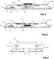
- a fan 13 ( Fig. 4 ) to arrange in the chimney 11, which can produce a, compared to the natural Konvezzysströmung larger air flow.
- the suction power of the fan 13 may be adapted to the generated power loss of the primary coil 2 and / or the charging electronics 3.
- the fan 13 should be resistant to media and contamination.
- the fan 13 should also allow a reversal of the air flow direction to clean the channels 10, air inlets 8 and chimneys 11 of dirt (blow-out function).
- openings 8, 9 of the channels 10 and the opening of the chimneys 11 could be provided with protective grids or the like.
- a liftable roof 12 ( Fig. 3 ).
- the roof 12 may also be provided as a cover with openings and fixed.
- the roof 12 may be overhanging, ie have a larger diameter than the chimney 11. But it could also be capable of lifting in the chimney 11, that is arranged with an inner diameter of the upper end of the fireplace corresponding outer diameter.
- the roof 12 may be provided with a logo and sensor means of the vehicle control for positioning the vehicle resp. the secondary coil 14 above the primary coil 2 included.
- the primary coil 2 could be designed to be capable of lifting in the z-direction as an alternative or in addition to the fan 13 in a further embodiment.
- Lifting and lowering the primary coil 2 can for Example by means of a telescope or scissors jack, the a bellows 15 ( Fig. 5 ). This allows on the one hand a more accurate positioning of the primary coil 2 to the secondary coil 14 and on the other hand due to the "fireplace increase" by the bellows 15 an increase in the chimney effect and thus the cooling of both the primary coil 2 and the secondary coil 14th
- the raised bellows 15 forms a dense, movable curtain or channel which encloses the space created by the lifting or at least the chimney 11.
- a bellows 15 and other elements for forming a curtain, channel or a fireplace extension are conceivable, for example, membranes, preferably elastic, or substantially rigid, extendable from recesses tubes or the like.
- the increase of the primary coil 2 for approaching the secondary coil 14 also contributes to the improvement of the inductive energy transfer between the primary part 1 and the secondary part.
- an adapted parking assistant could be used.
- the charging process can be started, for example, by means of an app and terminated when the maximum storage capacity of the battery is reached.
- the primary part 1 anchored to the ground and a power supply can be secured.
Landscapes
- Engineering & Computer Science (AREA)
- Power Engineering (AREA)
- Computer Networks & Wireless Communication (AREA)
- Transportation (AREA)
- Mechanical Engineering (AREA)
- Charge And Discharge Circuits For Batteries Or The Like (AREA)
- Electric Propulsion And Braking For Vehicles (AREA)
Claims (15)
- Partie primaire pour appareil de chargement, comprenant une face inférieure (6) et une face supérieure (7) ainsi que des surfaces latérales limitant la partie primaire (1) et comprenant une bobine primaire (2) pour le transfert inductif d'énergie à une bobine secondaire (14) d'un véhicule fonctionnant du moins partiellement à l'électricité, la bobine primaire (2) étant raccordée à une électronique de chargement (3) et disposée au niveau de ou adjacente à la face supérieure (7) de la partie primaire (1), au moins un canal (10) sortant d'une ouverture d'entrée (8) dans la partie proche du sol d'une des surfaces latérales de la partie primaire (1) réalisée sous forme de plaque de sol et présentant au moins une sous-section montante, caractérisée en ce que le canal (10) débouche dans au moins une cheminée ouverte (11) traversant de bas en haut la partie primaire (1) et ouverte vers le haut et montant dans au moins une sous-section jusqu'à l'embouchure dans l'au moins un cheminée (11).
- Partie primaire selon la revendication 1, caractérisée en ce qu'elle est pourvue de deux cheminées (11) traversant la partie primaire (1) du bas vers le haut.
- Partie primaire selon la revendication 1 ou 2, caractérisée en ce que, vue du dessus, elle a une conformation sensiblement rectangulaire ou ronde et que les surfaces latérales sont composées de biseaux (4).
- Partie primaire selon une des revendications 1 à 3, caractérisée en ce que l'au moins canal (10) a une conformation du moins partiellement ouverte et en forme de rainure vers le bas, la section transversale de la rainure se rétrécissant de préférence en direction de la cheminée (11).
- Partie primaire selon une des revendications 1 à 3, caractérisée en ce que la face inférieure (6) de la partie primaire (1) est pourvue de moyens d'établissement d'une distance ou d'un espace libre par rapport au sol.
- Partie primaire selon une des revendications 1 à 5, caractérisée en ce que la cheminée (11) est située au centre dans le sens z et est pourvue de nervures de refroidissement (17) tournées vers le centre de la cheminée (11).
- Partie primaire selon une des revendications 1 à 6, caractérisée en ce qu'il est prévu au niveau de chaque biseau (4) une ouverture d'entrée (8) d'un canal (10) débouchant dans la cheminée (11).
- Partie primaire selon une des revendications 1 à 7, caractérisée en ce que la bobine primaire (2) est réalisée de manière à pouvoir être levée dans le sens z.
- Partie primaire selon la revendication 8, caractérisée en ce que la bobine primaire (2) peut être levée au moyen d'un moyen de levage comportant un soufflet (15), le soufflet levé (15) constituant un rideau compact et mobile qui entoure au moins une cheminée (11).
- Partie primaire selon une des revendications 1 à 9, caractérisée en ce qu'un ventilateur (13, 16) est inséré dans la cheminée (11).
- Partie primaire selon une des revendications 1 à 10, caractérisée en ce que la cheminée (11) peut être recouverte au niveau de ou à proximité de la face supérieure (7) d'un toit non proéminent (12).
- Partie primaire selon une des revendications 1 à 11, caractérisée en ce que la bobine primaire (2) est disposée dans la partie primaire (1) en entourant la ou les cheminées (11) en une forme annulaire ou rectangulaire.
- Partie primaire selon une des revendications 1 à 12, caractérisée en ce que la bobine primaire (2) présente une section transversale rectangulaire ou arrondie.
- Appareil de chargement pour le transfert inductif d'énergie, comprenant une partie primaire (1) selon une des revendications 1 à 13 dotée d'une bobine primaire (2) à laquelle, en état de fonctionnement, une bobine secondaire (14) d'un véhicule fonctionnant du moins partiellement à l'électricité peut être associée.
- Appareil de chargement selon la revendication 14, caractérisée en ce que la partie primaire (1) est pourvue d'au moins une cheminée (11) traversant la partie primaire (1) du bas vers le haut et ouverte vers le haut, dans laquelle débouche au moins un canal (10) dont l'ouverture d'entrée (8) se situe dans la partie proche du sol d'une surface latérale de la plaque de sol (18) de la partie primaire (1) et qui monte au moins dans une sous-section jusqu'à l'embouchure dans l'au moins une cheminée (11).
Priority Applications (1)
| Application Number | Priority Date | Filing Date | Title |
|---|---|---|---|
| EP14176348.2A EP2965941B1 (fr) | 2014-07-09 | 2014-07-09 | Partie primaire pour un appareil de chargement inductif |
Applications Claiming Priority (1)
| Application Number | Priority Date | Filing Date | Title |
|---|---|---|---|
| EP14176348.2A EP2965941B1 (fr) | 2014-07-09 | 2014-07-09 | Partie primaire pour un appareil de chargement inductif |
Publications (2)
| Publication Number | Publication Date |
|---|---|
| EP2965941A1 EP2965941A1 (fr) | 2016-01-13 |
| EP2965941B1 true EP2965941B1 (fr) | 2017-09-13 |
Family
ID=51162553
Family Applications (1)
| Application Number | Title | Priority Date | Filing Date |
|---|---|---|---|
| EP14176348.2A Active EP2965941B1 (fr) | 2014-07-09 | 2014-07-09 | Partie primaire pour un appareil de chargement inductif |
Country Status (1)
| Country | Link |
|---|---|
| EP (1) | EP2965941B1 (fr) |
Cited By (1)
| Publication number | Priority date | Publication date | Assignee | Title |
|---|---|---|---|---|
| WO2025149325A1 (fr) * | 2024-01-12 | 2025-07-17 | Mahle International Gmbh | Ensemble de sol et système de recharge de véhicule |
Families Citing this family (6)
| Publication number | Priority date | Publication date | Assignee | Title |
|---|---|---|---|---|
| FR3070097B1 (fr) * | 2017-08-09 | 2021-05-07 | Continental Automotive France | Dispositif de charge par induction a evacuation de chaleur interne |
| DE102018009488A1 (de) | 2018-12-03 | 2019-06-27 | Daimler Ag | Abschlrmvorrlchtung und Verfahren zum Abschlrmen oder Entfernen elnes Fremdobjekts |
| EP3913764A1 (fr) * | 2020-05-20 | 2021-11-24 | Nokia Technologies Oy | Appareil de chargement |
| DE102022202925A1 (de) * | 2022-03-24 | 2023-09-28 | Mahle International Gmbh | Stationäre Induktionsladeeinrichtung |
| JP2025531670A (ja) * | 2022-09-08 | 2025-09-25 | ブルサ エレクトロニック アーゲー | 冷却が最適化された車両充電装置 |
| DE102022213357A1 (de) * | 2022-12-09 | 2024-06-20 | Mahle International Gmbh | Stationäre Induktionsladevorrichtung sowie induktives Fahrzeugladesystem mit derselben |
Family Cites Families (8)
| Publication number | Priority date | Publication date | Assignee | Title |
|---|---|---|---|---|
| DE4236286A1 (de) * | 1992-10-28 | 1994-05-05 | Daimler Benz Ag | Verfahren und Anordnung zum automatischen berührungslosen Laden |
| FR2732169B1 (fr) * | 1995-03-24 | 1997-05-09 | Peugeot | Dispositif pour recharger les batteries d'accumulateurs d'un vehicule electrique |
| DE102004039651A1 (de) | 2004-08-16 | 2006-03-09 | Giesecke & Devrient Gmbh | Gesteuertes kontaktloses Aufladen eines Akkumulators |
| RU2506181C2 (ru) * | 2009-07-15 | 2014-02-10 | Кондуктикс-Вампфлер Гмбх | Система для индуктивной зарядки транспортных средств, снабженных электронной системой позиционирования |
| DE102011108546A1 (de) * | 2011-07-26 | 2013-01-31 | Daimler Ag | Vorrichtung und Verfahren zum Laden eines Energiespeichers eines Fahrzeuges |
| DE102011118397A1 (de) * | 2011-11-12 | 2012-05-16 | Daimler Ag | Vorrichtung zum kabellosen Laden eines elektrischen Energiespeichers eines elektrisch angetriebenen Kraftfahrzeugs |
| DE102011089339A1 (de) | 2011-12-21 | 2013-06-27 | Continental Automotive Gmbh | Induktives Übertragen von Energie von einer Primärspule zu einer Sekundärspule eines elektromobilen Kraftfahrzeugs |
| DE102012020364A1 (de) | 2012-10-17 | 2014-04-17 | Panasonic Corporation | Verfahren zum Anregen von Primärspulen in einer kontaktlosen Leistungsversorgungsvorrichtung und kontaktlose Leistungsversorgungsvorrichtung |
-
2014
- 2014-07-09 EP EP14176348.2A patent/EP2965941B1/fr active Active
Non-Patent Citations (1)
| Title |
|---|
| None * |
Cited By (1)
| Publication number | Priority date | Publication date | Assignee | Title |
|---|---|---|---|---|
| WO2025149325A1 (fr) * | 2024-01-12 | 2025-07-17 | Mahle International Gmbh | Ensemble de sol et système de recharge de véhicule |
Also Published As
| Publication number | Publication date |
|---|---|
| EP2965941A1 (fr) | 2016-01-13 |
Similar Documents
| Publication | Publication Date | Title |
|---|---|---|
| EP2965941B1 (fr) | Partie primaire pour un appareil de chargement inductif | |
| EP3065152A1 (fr) | Partie primaire d'un appareil de chargement inductif | |
| EP3125355B1 (fr) | Dispositif pour un vehicule, en particulier pour un vehicule utilitaire | |
| WO2019101621A1 (fr) | Dispositif de charge sans fil d'un terminal mobile | |
| EP2689946B1 (fr) | Dispositif de chauffage | |
| DE202007018397U1 (de) | Thermoelektrische Temperiervorrichtung | |
| DE202015100764U1 (de) | Stapelbare Abschlussplatten für Kühleröffnungen | |
| EP2987670B1 (fr) | Dispositif de determination d'un debit d'air | |
| EP2760075B1 (fr) | Système de batterie avec boîtier | |
| DE102011090066A1 (de) | Lüftermodul | |
| WO2018172509A1 (fr) | Appareil de chauffage électrique | |
| WO2013156404A2 (fr) | Dispositif électrique de mise en temperature | |
| EP2993337B1 (fr) | Moteur d'aéronef ayant au moins un dispositif de prélèvement d'air | |
| DE102013222130A1 (de) | Wärmeübertrager | |
| DE102006025535A1 (de) | Vorrichtung zur Kühlung elektrischer Elemente | |
| EP2088012B1 (fr) | Appareil de chargement pour une batterie d'un véhicule | |
| EP3297089B1 (fr) | Chariot élévateur avec une batterie de traction | |
| DE102020134363B4 (de) | Ladeeinrichtung | |
| DE102017009640A1 (de) | Kühlvorrichtung | |
| DE102015106093A1 (de) | Klimaanlage für Fahrzeuge | |
| DE102022130590A1 (de) | Aufbewahrungsvorrichtung für ein Kraftfahrzeug sowie Kraftfahrzeug mit einer Aufbewahrungsvorrichtung | |
| DE102019211519A1 (de) | Ladevorrichtung zum drahtlosen Aufladen eines elektrischen Energiespeichers eines mobilen Endgeräts für ein Kraftfahrzeug sowie Kraftfahrzeug mit einer Ladevorrichtung | |
| DE102022203079A1 (de) | Stationäre Bodenbaugruppe für eine induktive Ladevorrichtung | |
| DE102018202131A1 (de) | Komponente für ein Kraftfahrzeug und Kraftfahrzeug | |
| WO1998050689A1 (fr) | Dispositif de refroidissement pour moteur a combustion interne d'un vehicule |
Legal Events
| Date | Code | Title | Description |
|---|---|---|---|
| PUAI | Public reference made under article 153(3) epc to a published international application that has entered the european phase |
Free format text: ORIGINAL CODE: 0009012 |
|
| AK | Designated contracting states |
Kind code of ref document: A1 Designated state(s): AL AT BE BG CH CY CZ DE DK EE ES FI FR GB GR HR HU IE IS IT LI LT LU LV MC MK MT NL NO PL PT RO RS SE SI SK SM TR |
|
| AX | Request for extension of the european patent |
Extension state: BA ME |
|
| 17P | Request for examination filed |
Effective date: 20160707 |
|
| RBV | Designated contracting states (corrected) |
Designated state(s): AL AT BE BG CH CY CZ DE DK EE ES FI FR GB GR HR HU IE IS IT LI LT LU LV MC MK MT NL NO PL PT RO RS SE SI SK SM TR |
|
| GRAP | Despatch of communication of intention to grant a patent |
Free format text: ORIGINAL CODE: EPIDOSNIGR1 |
|
| STAA | Information on the status of an ep patent application or granted ep patent |
Free format text: STATUS: GRANT OF PATENT IS INTENDED |
|
| INTG | Intention to grant announced |
Effective date: 20170411 |
|
| GRAS | Grant fee paid |
Free format text: ORIGINAL CODE: EPIDOSNIGR3 |
|
| GRAA | (expected) grant |
Free format text: ORIGINAL CODE: 0009210 |
|
| STAA | Information on the status of an ep patent application or granted ep patent |
Free format text: STATUS: THE PATENT HAS BEEN GRANTED |
|
| AK | Designated contracting states |
Kind code of ref document: B1 Designated state(s): AL AT BE BG CH CY CZ DE DK EE ES FI FR GB GR HR HU IE IS IT LI LT LU LV MC MK MT NL NO PL PT RO RS SE SI SK SM TR |
|
| REG | Reference to a national code |
Ref country code: GB Ref legal event code: FG4D Free format text: NOT ENGLISH |
|
| REG | Reference to a national code |
Ref country code: CH Ref legal event code: EP |
|
| REG | Reference to a national code |
Ref country code: IE Ref legal event code: FG4D Free format text: LANGUAGE OF EP DOCUMENT: GERMAN |
|
| REG | Reference to a national code |
Ref country code: AT Ref legal event code: REF Ref document number: 927793 Country of ref document: AT Kind code of ref document: T Effective date: 20171015 |
|
| REG | Reference to a national code |
Ref country code: DE Ref legal event code: R096 Ref document number: 502014005412 Country of ref document: DE |
|
| REG | Reference to a national code |
Ref country code: NL Ref legal event code: MP Effective date: 20170913 |
|
| REG | Reference to a national code |
Ref country code: LT Ref legal event code: MG4D |
|
| PG25 | Lapsed in a contracting state [announced via postgrant information from national office to epo] |
Ref country code: LT Free format text: LAPSE BECAUSE OF FAILURE TO SUBMIT A TRANSLATION OF THE DESCRIPTION OR TO PAY THE FEE WITHIN THE PRESCRIBED TIME-LIMIT Effective date: 20170913 Ref country code: NO Free format text: LAPSE BECAUSE OF FAILURE TO SUBMIT A TRANSLATION OF THE DESCRIPTION OR TO PAY THE FEE WITHIN THE PRESCRIBED TIME-LIMIT Effective date: 20171213 Ref country code: HR Free format text: LAPSE BECAUSE OF FAILURE TO SUBMIT A TRANSLATION OF THE DESCRIPTION OR TO PAY THE FEE WITHIN THE PRESCRIBED TIME-LIMIT Effective date: 20170913 Ref country code: SE Free format text: LAPSE BECAUSE OF FAILURE TO SUBMIT A TRANSLATION OF THE DESCRIPTION OR TO PAY THE FEE WITHIN THE PRESCRIBED TIME-LIMIT Effective date: 20170913 Ref country code: FI Free format text: LAPSE BECAUSE OF FAILURE TO SUBMIT A TRANSLATION OF THE DESCRIPTION OR TO PAY THE FEE WITHIN THE PRESCRIBED TIME-LIMIT Effective date: 20170913 |
|
| PG25 | Lapsed in a contracting state [announced via postgrant information from national office to epo] |
Ref country code: BG Free format text: LAPSE BECAUSE OF FAILURE TO SUBMIT A TRANSLATION OF THE DESCRIPTION OR TO PAY THE FEE WITHIN THE PRESCRIBED TIME-LIMIT Effective date: 20171213 Ref country code: LV Free format text: LAPSE BECAUSE OF FAILURE TO SUBMIT A TRANSLATION OF THE DESCRIPTION OR TO PAY THE FEE WITHIN THE PRESCRIBED TIME-LIMIT Effective date: 20170913 Ref country code: RS Free format text: LAPSE BECAUSE OF FAILURE TO SUBMIT A TRANSLATION OF THE DESCRIPTION OR TO PAY THE FEE WITHIN THE PRESCRIBED TIME-LIMIT Effective date: 20170913 Ref country code: ES Free format text: LAPSE BECAUSE OF FAILURE TO SUBMIT A TRANSLATION OF THE DESCRIPTION OR TO PAY THE FEE WITHIN THE PRESCRIBED TIME-LIMIT Effective date: 20170913 Ref country code: GR Free format text: LAPSE BECAUSE OF FAILURE TO SUBMIT A TRANSLATION OF THE DESCRIPTION OR TO PAY THE FEE WITHIN THE PRESCRIBED TIME-LIMIT Effective date: 20171214 |
|
| PG25 | Lapsed in a contracting state [announced via postgrant information from national office to epo] |
Ref country code: NL Free format text: LAPSE BECAUSE OF FAILURE TO SUBMIT A TRANSLATION OF THE DESCRIPTION OR TO PAY THE FEE WITHIN THE PRESCRIBED TIME-LIMIT Effective date: 20170913 |
|
| PG25 | Lapsed in a contracting state [announced via postgrant information from national office to epo] |
Ref country code: RO Free format text: LAPSE BECAUSE OF FAILURE TO SUBMIT A TRANSLATION OF THE DESCRIPTION OR TO PAY THE FEE WITHIN THE PRESCRIBED TIME-LIMIT Effective date: 20170913 Ref country code: CZ Free format text: LAPSE BECAUSE OF FAILURE TO SUBMIT A TRANSLATION OF THE DESCRIPTION OR TO PAY THE FEE WITHIN THE PRESCRIBED TIME-LIMIT Effective date: 20170913 Ref country code: PL Free format text: LAPSE BECAUSE OF FAILURE TO SUBMIT A TRANSLATION OF THE DESCRIPTION OR TO PAY THE FEE WITHIN THE PRESCRIBED TIME-LIMIT Effective date: 20170913 |
|
| PG25 | Lapsed in a contracting state [announced via postgrant information from national office to epo] |
Ref country code: SM Free format text: LAPSE BECAUSE OF FAILURE TO SUBMIT A TRANSLATION OF THE DESCRIPTION OR TO PAY THE FEE WITHIN THE PRESCRIBED TIME-LIMIT Effective date: 20170913 Ref country code: IS Free format text: LAPSE BECAUSE OF FAILURE TO SUBMIT A TRANSLATION OF THE DESCRIPTION OR TO PAY THE FEE WITHIN THE PRESCRIBED TIME-LIMIT Effective date: 20180113 Ref country code: IT Free format text: LAPSE BECAUSE OF FAILURE TO SUBMIT A TRANSLATION OF THE DESCRIPTION OR TO PAY THE FEE WITHIN THE PRESCRIBED TIME-LIMIT Effective date: 20170913 Ref country code: SK Free format text: LAPSE BECAUSE OF FAILURE TO SUBMIT A TRANSLATION OF THE DESCRIPTION OR TO PAY THE FEE WITHIN THE PRESCRIBED TIME-LIMIT Effective date: 20170913 Ref country code: EE Free format text: LAPSE BECAUSE OF FAILURE TO SUBMIT A TRANSLATION OF THE DESCRIPTION OR TO PAY THE FEE WITHIN THE PRESCRIBED TIME-LIMIT Effective date: 20170913 |
|
| REG | Reference to a national code |
Ref country code: DE Ref legal event code: R097 Ref document number: 502014005412 Country of ref document: DE |
|
| PLBE | No opposition filed within time limit |
Free format text: ORIGINAL CODE: 0009261 |
|
| STAA | Information on the status of an ep patent application or granted ep patent |
Free format text: STATUS: NO OPPOSITION FILED WITHIN TIME LIMIT |
|
| REG | Reference to a national code |
Ref country code: FR Ref legal event code: PLFP Year of fee payment: 5 |
|
| PG25 | Lapsed in a contracting state [announced via postgrant information from national office to epo] |
Ref country code: DK Free format text: LAPSE BECAUSE OF FAILURE TO SUBMIT A TRANSLATION OF THE DESCRIPTION OR TO PAY THE FEE WITHIN THE PRESCRIBED TIME-LIMIT Effective date: 20170913 |
|
| 26N | No opposition filed |
Effective date: 20180614 |
|
| PG25 | Lapsed in a contracting state [announced via postgrant information from national office to epo] |
Ref country code: MT Free format text: LAPSE BECAUSE OF FAILURE TO SUBMIT A TRANSLATION OF THE DESCRIPTION OR TO PAY THE FEE WITHIN THE PRESCRIBED TIME-LIMIT Effective date: 20170913 |
|
| PG25 | Lapsed in a contracting state [announced via postgrant information from national office to epo] |
Ref country code: SI Free format text: LAPSE BECAUSE OF FAILURE TO SUBMIT A TRANSLATION OF THE DESCRIPTION OR TO PAY THE FEE WITHIN THE PRESCRIBED TIME-LIMIT Effective date: 20170913 |
|
| REG | Reference to a national code |
Ref country code: DE Ref legal event code: R079 Ref document number: 502014005412 Country of ref document: DE Free format text: PREVIOUS MAIN CLASS: B60L0011180000 Ipc: B60L0050500000 |
|
| REG | Reference to a national code |
Ref country code: CH Ref legal event code: PL |
|
| PG25 | Lapsed in a contracting state [announced via postgrant information from national office to epo] |
Ref country code: MC Free format text: LAPSE BECAUSE OF FAILURE TO SUBMIT A TRANSLATION OF THE DESCRIPTION OR TO PAY THE FEE WITHIN THE PRESCRIBED TIME-LIMIT Effective date: 20170913 Ref country code: LU Free format text: LAPSE BECAUSE OF NON-PAYMENT OF DUE FEES Effective date: 20180709 |
|
| REG | Reference to a national code |
Ref country code: BE Ref legal event code: MM Effective date: 20180731 |
|
| REG | Reference to a national code |
Ref country code: IE Ref legal event code: MM4A |
|
| PG25 | Lapsed in a contracting state [announced via postgrant information from national office to epo] |
Ref country code: LI Free format text: LAPSE BECAUSE OF NON-PAYMENT OF DUE FEES Effective date: 20180731 Ref country code: IE Free format text: LAPSE BECAUSE OF NON-PAYMENT OF DUE FEES Effective date: 20180709 Ref country code: CH Free format text: LAPSE BECAUSE OF NON-PAYMENT OF DUE FEES Effective date: 20180731 |
|
| PG25 | Lapsed in a contracting state [announced via postgrant information from national office to epo] |
Ref country code: BE Free format text: LAPSE BECAUSE OF NON-PAYMENT OF DUE FEES Effective date: 20180731 |
|
| PG25 | Lapsed in a contracting state [announced via postgrant information from national office to epo] |
Ref country code: TR Free format text: LAPSE BECAUSE OF FAILURE TO SUBMIT A TRANSLATION OF THE DESCRIPTION OR TO PAY THE FEE WITHIN THE PRESCRIBED TIME-LIMIT Effective date: 20170913 |
|
| PG25 | Lapsed in a contracting state [announced via postgrant information from national office to epo] |
Ref country code: PT Free format text: LAPSE BECAUSE OF FAILURE TO SUBMIT A TRANSLATION OF THE DESCRIPTION OR TO PAY THE FEE WITHIN THE PRESCRIBED TIME-LIMIT Effective date: 20170913 |
|
| PG25 | Lapsed in a contracting state [announced via postgrant information from national office to epo] |
Ref country code: HU Free format text: LAPSE BECAUSE OF FAILURE TO SUBMIT A TRANSLATION OF THE DESCRIPTION OR TO PAY THE FEE WITHIN THE PRESCRIBED TIME-LIMIT; INVALID AB INITIO Effective date: 20140709 Ref country code: CY Free format text: LAPSE BECAUSE OF FAILURE TO SUBMIT A TRANSLATION OF THE DESCRIPTION OR TO PAY THE FEE WITHIN THE PRESCRIBED TIME-LIMIT Effective date: 20170913 Ref country code: MK Free format text: LAPSE BECAUSE OF NON-PAYMENT OF DUE FEES Effective date: 20170913 |
|
| PG25 | Lapsed in a contracting state [announced via postgrant information from national office to epo] |
Ref country code: AL Free format text: LAPSE BECAUSE OF FAILURE TO SUBMIT A TRANSLATION OF THE DESCRIPTION OR TO PAY THE FEE WITHIN THE PRESCRIBED TIME-LIMIT Effective date: 20170913 |
|
| REG | Reference to a national code |
Ref country code: AT Ref legal event code: MM01 Ref document number: 927793 Country of ref document: AT Kind code of ref document: T Effective date: 20190709 |
|
| PG25 | Lapsed in a contracting state [announced via postgrant information from national office to epo] |
Ref country code: AT Free format text: LAPSE BECAUSE OF NON-PAYMENT OF DUE FEES Effective date: 20190709 |
|
| PGFP | Annual fee paid to national office [announced via postgrant information from national office to epo] |
Ref country code: DE Payment date: 20250723 Year of fee payment: 12 |
|
| PGFP | Annual fee paid to national office [announced via postgrant information from national office to epo] |
Ref country code: GB Payment date: 20250724 Year of fee payment: 12 |
|
| PGFP | Annual fee paid to national office [announced via postgrant information from national office to epo] |
Ref country code: FR Payment date: 20250718 Year of fee payment: 12 |