EP2966043A2 - Wasserzuflusssystem (ifs) und sandfangbehälter für wasserklärsysteme - Google Patents
Wasserzuflusssystem (ifs) und sandfangbehälter für wasserklärsysteme Download PDFInfo
- Publication number
- EP2966043A2 EP2966043A2 EP15175703.6A EP15175703A EP2966043A2 EP 2966043 A2 EP2966043 A2 EP 2966043A2 EP 15175703 A EP15175703 A EP 15175703A EP 2966043 A2 EP2966043 A2 EP 2966043A2
- Authority
- EP
- European Patent Office
- Prior art keywords
- influent
- grit
- feed system
- materials
- pipes
- Prior art date
- Legal status (The legal status is an assumption and is not a legal conclusion. Google has not performed a legal analysis and makes no representation as to the accuracy of the status listed.)
- Withdrawn
Links
- 238000005352 clarification Methods 0.000 title claims abstract description 24
- XLYOFNOQVPJJNP-UHFFFAOYSA-N water Substances O XLYOFNOQVPJJNP-UHFFFAOYSA-N 0.000 title description 5
- 239000000463 material Substances 0.000 claims abstract description 55
- 238000004891 communication Methods 0.000 claims abstract description 51
- 239000012530 fluid Substances 0.000 claims abstract description 49
- 230000007246 mechanism Effects 0.000 claims abstract description 11
- 239000013618 particulate matter Substances 0.000 claims abstract description 7
- 238000009825 accumulation Methods 0.000 claims abstract description 3
- 239000007787 solid Substances 0.000 claims description 47
- 239000008394 flocculating agent Substances 0.000 claims description 20
- 230000004044 response Effects 0.000 claims description 8
- 238000000926 separation method Methods 0.000 claims description 6
- 230000005484 gravity Effects 0.000 claims description 5
- 238000000429 assembly Methods 0.000 claims description 3
- 230000000712 assembly Effects 0.000 claims description 3
- 238000010586 diagram Methods 0.000 description 14
- 238000011282 treatment Methods 0.000 description 11
- 238000000034 method Methods 0.000 description 10
- 238000004065 wastewater treatment Methods 0.000 description 10
- 239000007788 liquid Substances 0.000 description 9
- 238000000151 deposition Methods 0.000 description 6
- 238000012423 maintenance Methods 0.000 description 5
- 239000002351 wastewater Substances 0.000 description 5
- 230000008021 deposition Effects 0.000 description 4
- 238000011221 initial treatment Methods 0.000 description 4
- 239000004576 sand Substances 0.000 description 4
- 239000010802 sludge Substances 0.000 description 4
- 239000000126 substance Substances 0.000 description 4
- 238000013461 design Methods 0.000 description 3
- 239000000654 additive Substances 0.000 description 2
- 230000000996 additive effect Effects 0.000 description 2
- 230000008901 benefit Effects 0.000 description 2
- 238000004140 cleaning Methods 0.000 description 2
- 239000002440 industrial waste Substances 0.000 description 2
- 238000005065 mining Methods 0.000 description 2
- 239000002245 particle Substances 0.000 description 2
- 230000008569 process Effects 0.000 description 2
- 230000000630 rising effect Effects 0.000 description 2
- 238000009991 scouring Methods 0.000 description 2
- 239000010865 sewage Substances 0.000 description 2
- RZVAJINKPMORJF-UHFFFAOYSA-N Acetaminophen Chemical compound CC(=O)NC1=CC=C(O)C=C1 RZVAJINKPMORJF-UHFFFAOYSA-N 0.000 description 1
- 241000196324 Embryophyta Species 0.000 description 1
- 241000610007 Rauvolfia vomitoria Species 0.000 description 1
- 230000015572 biosynthetic process Effects 0.000 description 1
- 230000008859 change Effects 0.000 description 1
- 239000000470 constituent Substances 0.000 description 1
- 230000003247 decreasing effect Effects 0.000 description 1
- 238000005516 engineering process Methods 0.000 description 1
- 238000005189 flocculation Methods 0.000 description 1
- 230000016615 flocculation Effects 0.000 description 1
- 238000004519 manufacturing process Methods 0.000 description 1
- 239000010841 municipal wastewater Substances 0.000 description 1
- 239000002244 precipitate Substances 0.000 description 1
- 238000011084 recovery Methods 0.000 description 1
- 230000003068 static effect Effects 0.000 description 1
- 238000012546 transfer Methods 0.000 description 1
Images






Classifications
-
- C—CHEMISTRY; METALLURGY
- C02—TREATMENT OF WATER, WASTE WATER, SEWAGE, OR SLUDGE
- C02F—TREATMENT OF WATER, WASTE WATER, SEWAGE, OR SLUDGE
- C02F1/00—Treatment of water, waste water, or sewage
- C02F1/52—Treatment of water, waste water, or sewage by flocculation or precipitation of suspended impurities
- C02F1/5281—Installations for water purification using chemical agents
-
- B—PERFORMING OPERATIONS; TRANSPORTING
- B01—PHYSICAL OR CHEMICAL PROCESSES OR APPARATUS IN GENERAL
- B01D—SEPARATION
- B01D21/00—Separation of suspended solid particles from liquids by sedimentation
- B01D21/0024—Inlets or outlets provided with regulating devices, e.g. valves, flaps
-
- B—PERFORMING OPERATIONS; TRANSPORTING
- B01—PHYSICAL OR CHEMICAL PROCESSES OR APPARATUS IN GENERAL
- B01D—SEPARATION
- B01D21/00—Separation of suspended solid particles from liquids by sedimentation
- B01D21/0039—Settling tanks provided with contact surfaces, e.g. baffles, particles
- B01D21/0057—Settling tanks provided with contact surfaces, e.g. baffles, particles with counter-current flow direction of liquid and solid particles
-
- B—PERFORMING OPERATIONS; TRANSPORTING
- B01—PHYSICAL OR CHEMICAL PROCESSES OR APPARATUS IN GENERAL
- B01D—SEPARATION
- B01D21/00—Separation of suspended solid particles from liquids by sedimentation
- B01D21/0087—Settling tanks provided with means for ensuring a special flow pattern, e.g. even inflow or outflow
-
- B—PERFORMING OPERATIONS; TRANSPORTING
- B01—PHYSICAL OR CHEMICAL PROCESSES OR APPARATUS IN GENERAL
- B01D—SEPARATION
- B01D21/00—Separation of suspended solid particles from liquids by sedimentation
- B01D21/01—Separation of suspended solid particles from liquids by sedimentation using flocculating agents
-
- B—PERFORMING OPERATIONS; TRANSPORTING
- B01—PHYSICAL OR CHEMICAL PROCESSES OR APPARATUS IN GENERAL
- B01D—SEPARATION
- B01D21/00—Separation of suspended solid particles from liquids by sedimentation
- B01D21/02—Settling tanks with single outlets for the separated liquid
-
- B—PERFORMING OPERATIONS; TRANSPORTING
- B01—PHYSICAL OR CHEMICAL PROCESSES OR APPARATUS IN GENERAL
- B01D—SEPARATION
- B01D21/00—Separation of suspended solid particles from liquids by sedimentation
- B01D21/24—Feed or discharge mechanisms for settling tanks
- B01D21/2427—The feed or discharge opening located at a distant position from the side walls
-
- B—PERFORMING OPERATIONS; TRANSPORTING
- B01—PHYSICAL OR CHEMICAL PROCESSES OR APPARATUS IN GENERAL
- B01D—SEPARATION
- B01D21/00—Separation of suspended solid particles from liquids by sedimentation
- B01D21/28—Mechanical auxiliary equipment for acceleration of sedimentation, e.g. by vibrators or the like
-
- B—PERFORMING OPERATIONS; TRANSPORTING
- B01—PHYSICAL OR CHEMICAL PROCESSES OR APPARATUS IN GENERAL
- B01D—SEPARATION
- B01D21/00—Separation of suspended solid particles from liquids by sedimentation
- B01D21/30—Control equipment
- B01D21/34—Controlling the feed distribution; Controlling the liquid level ; Control of process parameters
-
- B—PERFORMING OPERATIONS; TRANSPORTING
- B01—PHYSICAL OR CHEMICAL PROCESSES OR APPARATUS IN GENERAL
- B01F—MIXING, e.g. DISSOLVING, EMULSIFYING OR DISPERSING
- B01F25/00—Flow mixers; Mixers for falling materials, e.g. solid particles
- B01F25/20—Jet mixers, i.e. mixers using high-speed fluid streams
- B01F25/23—Mixing by intersecting jets
-
- B—PERFORMING OPERATIONS; TRANSPORTING
- B01—PHYSICAL OR CHEMICAL PROCESSES OR APPARATUS IN GENERAL
- B01F—MIXING, e.g. DISSOLVING, EMULSIFYING OR DISPERSING
- B01F25/00—Flow mixers; Mixers for falling materials, e.g. solid particles
- B01F25/40—Static mixers
- B01F25/42—Static mixers in which the mixing is affected by moving the components jointly in changing directions, e.g. in tubes provided with baffles or obstructions
- B01F25/421—Static mixers in which the mixing is affected by moving the components jointly in changing directions, e.g. in tubes provided with baffles or obstructions by moving the components in a convoluted or labyrinthine path
- B01F25/423—Static mixers in which the mixing is affected by moving the components jointly in changing directions, e.g. in tubes provided with baffles or obstructions by moving the components in a convoluted or labyrinthine path by means of elements placed in the receptacle for moving or guiding the components
- B01F25/4231—Static mixers in which the mixing is affected by moving the components jointly in changing directions, e.g. in tubes provided with baffles or obstructions by moving the components in a convoluted or labyrinthine path by means of elements placed in the receptacle for moving or guiding the components using baffles
-
- B—PERFORMING OPERATIONS; TRANSPORTING
- B01—PHYSICAL OR CHEMICAL PROCESSES OR APPARATUS IN GENERAL
- B01F—MIXING, e.g. DISSOLVING, EMULSIFYING OR DISPERSING
- B01F25/00—Flow mixers; Mixers for falling materials, e.g. solid particles
- B01F25/40—Static mixers
- B01F25/42—Static mixers in which the mixing is affected by moving the components jointly in changing directions, e.g. in tubes provided with baffles or obstructions
- B01F25/43—Mixing tubes, e.g. wherein the material is moved in a radial or partly reversed direction
- B01F25/433—Mixing tubes wherein the shape of the tube influences the mixing, e.g. mixing tubes with varying cross-section or provided with inwardly extending profiles
- B01F25/4332—Mixers with a strong change of direction in the conduit for homogenizing the flow
-
- C—CHEMISTRY; METALLURGY
- C02—TREATMENT OF WATER, WASTE WATER, SEWAGE, OR SLUDGE
- C02F—TREATMENT OF WATER, WASTE WATER, SEWAGE, OR SLUDGE
- C02F1/00—Treatment of water, waste water, or sewage
- C02F1/008—Control or steering systems not provided for elsewhere in subclass C02F
-
- C—CHEMISTRY; METALLURGY
- C02—TREATMENT OF WATER, WASTE WATER, SEWAGE, OR SLUDGE
- C02F—TREATMENT OF WATER, WASTE WATER, SEWAGE, OR SLUDGE
- C02F1/00—Treatment of water, waste water, or sewage
- C02F2001/007—Processes including a sedimentation step
-
- C—CHEMISTRY; METALLURGY
- C02—TREATMENT OF WATER, WASTE WATER, SEWAGE, OR SLUDGE
- C02F—TREATMENT OF WATER, WASTE WATER, SEWAGE, OR SLUDGE
- C02F2209/00—Controlling or monitoring parameters in water treatment
- C02F2209/40—Liquid flow rate
-
- C—CHEMISTRY; METALLURGY
- C02—TREATMENT OF WATER, WASTE WATER, SEWAGE, OR SLUDGE
- C02F—TREATMENT OF WATER, WASTE WATER, SEWAGE, OR SLUDGE
- C02F2209/00—Controlling or monitoring parameters in water treatment
- C02F2209/42—Liquid level
-
- C—CHEMISTRY; METALLURGY
- C02—TREATMENT OF WATER, WASTE WATER, SEWAGE, OR SLUDGE
- C02F—TREATMENT OF WATER, WASTE WATER, SEWAGE, OR SLUDGE
- C02F2209/00—Controlling or monitoring parameters in water treatment
- C02F2209/44—Time
-
- C—CHEMISTRY; METALLURGY
- C02—TREATMENT OF WATER, WASTE WATER, SEWAGE, OR SLUDGE
- C02F—TREATMENT OF WATER, WASTE WATER, SEWAGE, OR SLUDGE
- C02F2301/00—General aspects of water treatment
- C02F2301/02—Fluid flow conditions
- C02F2301/024—Turbulent
-
- C—CHEMISTRY; METALLURGY
- C02—TREATMENT OF WATER, WASTE WATER, SEWAGE, OR SLUDGE
- C02F—TREATMENT OF WATER, WASTE WATER, SEWAGE, OR SLUDGE
- C02F2301/00—General aspects of water treatment
- C02F2301/04—Flow arrangements
-
- C—CHEMISTRY; METALLURGY
- C02—TREATMENT OF WATER, WASTE WATER, SEWAGE, OR SLUDGE
- C02F—TREATMENT OF WATER, WASTE WATER, SEWAGE, OR SLUDGE
- C02F2303/00—Specific treatment goals
- C02F2303/24—Separation of coarse particles, e.g. by using sieves or screens
-
- C—CHEMISTRY; METALLURGY
- C02—TREATMENT OF WATER, WASTE WATER, SEWAGE, OR SLUDGE
- C02F—TREATMENT OF WATER, WASTE WATER, SEWAGE, OR SLUDGE
- C02F2305/00—Use of specific compounds during water treatment
- C02F2305/12—Inert solids used as ballast for improving sedimentation
Definitions
- the application relates to waste water separation, recovery, and clarification systems.
- Waste water treatment systems are used in a number of applications including but not limited to the treatment of sewage, storm water, industrial waste, mining and agriculture.
- Current waste water treatment systems maintain a continuous flow of influent entering the primary settling tank and effluent exiting the primary settling tank for secondary treatment resulting in in the incomplete removal of grit, solids and particulates and little if any separation of desirable materials from undesirable materials.
- an influent feed system to classify and separate particulate matter and solvated materials from an influent stream includes one or more influent feed troughs in fluid communication with a clarification tank.
- the influent feed troughs have dimensions such that an influent feed trough fluid rise rate that is less than the settling rate of materials to be deposited in the influent feed troughs.
- One or more grit boxes are in fluid communication with the one or more influent feed troughs.
- the one or more grit boxes have grit box dimensions which result in a grit box fluid rise rate that is slow relative to the settling rate of materials to be deposited in the one or more grit boxes.
- the one or moregrit boxes include a hopper for accumulation of the materials to be deposited.
- the hopper has a drainage pipe and a valve that controls communication of materials between the influent feed system and the drainage pipe.
- a mechanism delivers the influent stream at a predetermined and a substantially constant flow rate.
- the influent stream is separated into two or more streams and recombined under pressure in the grit boxes.
- the influent feed system further includes an apparatus to add one or more flocculants to the influent stream before the influent stream enters the one or more influent feed troughs.
- the influent feed system further includes an apparatus to add one or more flocculants to the influent stream as the influent stream separated into two or more streams recombines under pressure in the grit box.
- the influent stream delivery mechanism includes a reservoir which accumulates and stores influent, and one or more pumps that pump the influent to the influent feed system and a signal source which turns the pumps on.
- the influent stream delivery mechanism includes a reservoir to accumulate and store influent.
- the reservoir is elevated relative to the influent feed system and in fluid communication with the influent feed system.
- a control valve is disposed between the reservoir and the influent feed system. The control valve is configured to deliver the influent stream at the pre-determined and substantially constant flow rate, the control valve opening in response to a signal source to permit influent to traverse under an influence of gravity to the one or more grit boxes.
- the reservoir includes a holding tower.
- the influent feed system further includes a flow meter that measures a flow rate of fluid wherein the system closes the valve in response to the flow rate falling below a predetermined rate.
- the influent feed system includes one or more screen box assemblies that discharge influent from a settling tank after separation of solids from the influent stream.
- At least one of the one or more influent feed troughs further comprises one or more additional drain pipes in fluid communication with the at least one of the one or more influent feed troughs and another valve disposed between the at least one of the one or more influent feed troughs and an outflow end of the at least one of the one or more additional drain pipes controls a flow of materials through the outflow end.
- a grit box to classify and separate particulate matter and solvated materials from an influent stream includes an upper portion and a lower portion.
- the upper portion has a fluid discharge mechanism.
- the lower portion is coupled to a drainage pipe.
- the lower portion has a valve that controls communication of materials between an influent feed system and the drainage pipe.
- One or more of the dimensions of the upper portion and the lower portion causes a fluid rise rate slow relative to the settling rate of materials to be deposited in the grit box.
- a deflection plate is positioned between the upper portion and the lower portion.
- An influent stream delivery mechanism is configured to deliver the influent stream at a predetermined and substantially constant flow rate.
- the influent stream is separated into two or more streams and recombined under pressure in the lower portion.
- a hopper accumulates one or more deposited materials.
- the influent is recombined under pressure in the lower portion underneath the deflection plate.
- the influent is recombined in a turbulent mixing zone created by streams under pressure from two or more opposing pipes.
- the influent is recombined in the turbulent mixing zone created by streams under pressure directed substantially towards each other from three or more opposing pipes that extend from a manifold at about an equal angular spacing.
- three opposing pipes extend from the manifold at about a 120 degree spacing.
- four opposing pipes extend from the manifold at about a 90 degree spacing.
- each of the opposing pipes includes a first substantially 90 degree bend about where each of the opposing pipes is coupled to the manifold and a second substantially 90 degree bend that directs streams under pressure substantially towards each other.
- the opposing pipes include four opposing pipes that extend from the manifold at about a 90 degree spacing.
- Each of the opposing pipes includes a first substantially 90 degree bend about where each of the opposing pipes is coupled to the manifold.
- a first two opposing pipes of the four opposing pipes include a second upwards bend of greater than 90 degrees that direct the streams under pressure in an upwards direction and substantially towards each other.
- a two remaining opposing pipes of the four opposing pipes include a second downward bend of less than 90 degrees that directs the streams under pressure in a downwards direction and substantially towards each other and the streams emanating from the first two opposing pipes.
- Waste water treatment systems are used in a number of applications including but not limited to the treatment of sewage, storm water, industrial waste, mining and agriculture.
- Current waste water treatment systems maintain a continuous flow of influent entering the primary settling tank and effluent exiting the primary settling tank for secondary treatment resulting in in the incomplete removal of grit, solids and particulates and little if any separation of desirable materials from undesirable materials.
- a clarification system incorporating an improved Influent Feed System can be used to more efficiently classify and separate grits, solids, particulates and solvated materials from an influent stream.
- IFS Influent Feed System
- the IFS includes one or more grit boxes and one or more IFS troughs.
- the IFS can be arranged to classify solids by the creation of selected regions with predetermined influent rise velocities. Classification of solids can be done by the solids settling rates and, optionally, via the addition of flocculants to settle suspended and solvated materials. In this manner selected materials can be removed from the influent stream before it spills over the IFS Trough weir into a clarification settling tank where predominantly desirable materials are separated from the influent stream.
- the low rise rate and velocities of the influent as it traverses the IFS trough and grit box en route to a clarification settling tank provide the opportunity to avoid use of a bar screen, to separate the IFS trough from the interior the settling tank. Occasionally a bar rack will be used to control large solids from entering the main settling zone of the tank.
- the mixing of the flocculants and influent can be controlled to cause deposition of the floc in a predetermined portion of the IFS.
- system maintenance can be substantially minimized.
- the influent entering the IFS first enters a grit box.
- the influent stream is split into two or more separate streams which are then recombined under pressure to create a turbulent mixing of the recombined streams with a flocculent.
- Flocculants are added to the influent prior to influent entering the IFS, in the IFS or in the grit box.
- the turbulent mixing promotes rapid action of the flocculent with the solids and/or solvated materials, reducing or eliminating the need for sand and results in the deposition of the flocs in a controlled portion of the clarification system.
- the grit box has a turbulence deflector which is a curved or angular plate to return upward velocities back into the main mixing zone.
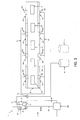
- FIG. 1 shows a block diagram of one exemplary embodiment of aclarification system 1 configured to selectively classify and separate grits, solids, particulates and solvated materials from an influent stream.
- the influent enters the clarification system 1 via pipes 11 where it is stored in wet well 12.
- a settling tank 30 is in fluid communication with 8 IFS's, 100-107.
- Pump 13 pumps influent from the wet well 12 to IFS's 100-107 at a substantially constant flow rate via piping 14, 15 and 15'.
- pump 13 operates under the control of a supervisory control and data acquisition system (SCADA) 900 in communication with pump 13 via communication channel 901.
- SCADA supervisory control and data acquisition system
- the SCADA 900 turns pump 13 on in response to an indication of the wet well 12 fluid level reaching an upper limit, the indication provided by sensor 18 in communication with SCADA 900 via communication channel 907.
- SCADA 900 turns pump 13 off in response to an indication of the wet well 12 fluid level reaching a lower limit, the indication provided by sensor 19 in communication with SCADA 900 via communication channel 908.
- SCADA 900 turns pump 13 off after a pre-determined period of time.
- SCADA 900 turns pump 13 off after a predetermine volume of fluid has been pumped as indicated by measuring the flow via signals provided by flow meter 25 in communication with SCADA 900 via communication channel 909.
- Flow meters and sensors to measure fluid level are well known in the art.
- piping 14, 15 and 15' is configured to deliver substantially the same flow rate of influent to each IFS 100-107.
- Flow balancing valves and/or flow splitting may be used.
- the influent enters the IFS's 100-107 where grits, solids, and optionally solvated materials, are selectively classified and separated from the influent via settling and optional flocculation. Materials settled in the IFS's 100-107 are removed via discharge pipes 570-577 as described in more detail with reference to FIG. 6 .
- the influent traverses the IFS's 100-107 to enter the clarification settling tank 30.
- FIG. 2 shows a block diagram of another exemplary embodiment of a clarification system 2configured to selectively classify and separate grits, solids, particulates and solvated materials from an influent stream.
- pump 13 pumps influent from the wet well 12 via piping 16 to influent holding tower 20.
- pump 13 operates under the control of a supervisory control and data acquisition system (SCADA) 900 in communication with pump 13 via communication channel 901.Holding tower 20stores influent at an elevated position relative to the IFS's 100-107.
- SCADA supervisory control and data acquisition system
- valve 21 is opened and influent is discharged from the influent holding tower 20 under the influence of gravity, traversing piping 14, 15 and 15' at pre-determined and substantially constant range of flow rates to enter the IFS's 100-107.
- valve 21 is under control of and in communication with SCADA 900 via communication channel 902.
- SCADA 900 sends a signal via communication channel 902 to open valve 21 in response to sensor 26 sending a signal to SCADA 900 via communication channel 905 indicating the fluid level in holding tower 20 is at or above a pre-determined limit.
- Sensors to measure fluid level are well known in the art.
- a flow meter 23 placed on pipe 14 in communication with SCADA 900 via communication channel 904 is used to monitor the rate of flow of fluid flowing from holding tower 20.
- Modulating valve/gate 22 are placed on pipe 14 under the control of SCADA 900 via communication channel 903 is used to regulate the flow within predetermined limit and compensate for variations in the head pressure that result from changes in the fluid of the influent holding tower 20 level as influent is discharged.
- SCADA 900 closes valve 21 in response to an indication of the holding tower 20 fluid level reaching a lower limit, the indication provided by fluid level sensor 27 in communication with SCADA 900 via communication channel 902.
- SCADA 900 closes valve 21 after a pre-determined period of time.
- SCADA 900 closes valve 21 after a predetermine volume of fluid has traversed pipe 14 as determined from measuring the total flow via signals provided by flow meter 23 in communication with SCADA 900 via communication channel 904.
- SCADA 900 closes valve 21 when the flow rate falls below a predetermine flow rate as indicated by a signal provided by flow meter 23 in communication with SCADA 900 via communication channel 904
- flocculants are optionally added to the influent stream by flocculent delivery systems 40, 41.
- flocculants for the removal of solids and solvated materials in the treatment of waste water and designs to add flocculants to an influent waste water stream are well known in the art. Flocculants are most effective when they are adequately mixed with the influent.
- FIG. 3A shows a diagram of a current influent and flocculent mixing device.
- FIG. 3B shows a diagram of an alternative current influent and flocculent mixing device.
- Currents systems 800, FIG. 3A and 850, FIG. 3B rely upon creating zones of turbulence 802, 852 to mix the flocculent and influent in the piping 801, FIG. 3A and 851, FIG. 3B used to transport the influent and flocculent through the clarification system to the region where settlingis desired. Over time, the mixing of influent and flocculants prior to the region of the clarification systems where settlingof the floc is desired results in deposits that impact the influent flow rate resulting in the need to perform costly and time-consuming maintenance.
- FIG. 4 shows a cross section diagram of an exemplary grit box.
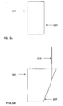
- FIG. 5A shows a side view of an exemplary influent feed system (IFS) trough.
- FIG. 5B shows an end view of an alternative embodiment of an IFS trough.
- IFS influent feed system
- FIG. 6 shows a side view of an exemplary IFS 100 with IFS troughs and grit box.
- FIG. 7 shows a top view of the IFS of FIG. 6 .
- a mixing zone is created within a grit box 500 at the location where deposition of the floc is desired.
- IFS 100 is configured with a grit box 500 and two IFS troughs 201, 202, having trough walls 207, 208.
- IFS troughs 201, 202 are in fluid communication with the grit box 500. Influent is delivered to the IFS 100 via pipe 501 and split into two streams which enter the grit box 500 via pipes 502, 503.
- a deflector plate 505 is positioned above the mixing zone 504 to confine the volume of the mixing zone and return the upward velocities of the streams existing pipes 502, 503 back into the Mixing Zone 504.
- Grit, dense solids and floc are deposited in the grit box hopper 506.
- the length of the pipes 502, 503 is arranged to position the mixing zone 504 below the lowest portion of the IFS troughs 201, 202 in proximity to and in fluid communication with the grit box 500.
- the mixing zone 504 and grit box hopper 506 are positioned below the lowest portion of the IFS troughs 201, 202 in proximity to and in fluid communication with the grit box 500. Solids with a lower settling rate than the designed influent rise velocity in the grit box hopper 506 move into the IFS troughs 201, 202.
- the solids moving upward under the influence of the rising influent undergo a 90 degree change in direction, turning from vertical to horizontal thus losing inertia and lessening the fluid forces on the suspended grits, solids and floc.
- a deflection plate 505 is positioned above the mixing zone 504.
- the deflection plate 505 is a curved or angular plate to keep sludge from settling on top of the deflection plate 505 and to return mixing velocities to mixing zone 504.
- FIG. 8A shows a diagram of a top view of an alternative configuration for mixing of influent streams in a grit box.
- FIG. 8B shows a side view of the apparatus of FIG. 8A .
- pipe 501 is in fluid communication with a manifold 510 that further splits the influent stream into three streams which enter the Grit Box 500 via pipes 511, 512, 513 arranged radially around manifold 510 at positions 120 degrees from one another.
- the influent streams exit the pipes 511, 512, 513 to collide to create a turbulent mixing zone 504.
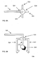
- FIG. 9A shows a diagram of a top view of another alternative configuration for mixing of influent streams in a grit box.
- FIG. 9B shows a side view of the apparatus of FIG. 9A .
- pipe 501 is in fluid communication with a manifold 520 that further splits the influent stream which enter the grit box 500 into four streams via pipes 521, 522, 523, 524 arranged radially around manifold 510 at positions 90 degrees from one another.
- pipes 522 and 524 are longer than pipes 521 and 523, and fabricated to cause the exiting influent to be ejected in an upwards direction to mixing zone 504.
- Pipes 521 and 523 are fabricated to cause the exiting influent to be ejected in a downwards direction to mixing zone 504.
- the four streams collide to create a turbulent Mixing Zone 504
- the materials settled in the grit box 500 can be removed as part of the routine operation of the clarification system by the scouring of the IFS with a fluid.
- materials in one embodiment fluid is pumped through pipes 410, 415 to scour the IFS troughs and grit box.
- the materials settled in the grit box 500 can be removed via discharge pipe 570 in liquid communication with the IFS. Fluid communication via discharge pipe 570 is controlled by valve 580.
- Valve 580 may be a manually operated valve.
- valve 580 is electronically controlled by a supervisory control and data acquisition system SCADA 900 which provides a signal via communication channel 910 to open and close the valve 580.
- valve 580 is opened to remove the settled materials when the IFS is full of influent. The head pressure from the influent assists in moving the settled solids from the grit box 500 through the discharge pipe 570.
- valve 580 is opened and the IFS troughs 201, 202 are scoured with liquid to evacuate solids from the entirety of the IFS.
- the influent feed trough may also have a separate valved drain pipe (one or more additional drain pipes) to direct accumulated materials to alternate or the same type of process as the grit box materials.
- a separate valved drain pipe one or more additional drain pipes
- materials settled in the IFS troughs, 201, 202 are removed separately from the materials settled in the grit box 500 via optional discharge pipes 578. 579.
- the materials settling in the IFS troughs 201, 202 and grit box 500 have may have differing composition due to the differing fluent rise rates in the IFS troughs 201, 202 and grit box 500 as well as the kinetics associated with floc formation.
- valves 588, 589 Fluid communication via discharge pipes 578, 598 are controlled by valves 588, 589 (typically in embodiments where valves 588, 589 are used, they are present in addition to valve 580). Valves 588, 589 may be manually operated valves. In an alternate embodiment, valves 588, 589 are electronically controlled by a supervisory control and data acquisition system SCADA 900 which provides a signal via communication channels 911, 921 to open and close valves 588, 589.
- SCADA 900 supervisory control and data acquisition system
- the influent stream is pumped at an overall flow rate sufficient to accommodate the maximum projected throughput that the plant will handle, such as during a flood or severe rainstorm.
- the velocity of the influent in pipes 14, 15, 15' ( FIG. 1 and FIG. 2 ), 501, 502, 503 should be fast enough to avoid plugging the influent pipes with solids, but not so fast as to scour and wear pipes and pipe elbows.
- Typical influent flow velocities are in the range of 3 to 8 feet per second.
- the diameter of the pipes 501, 502, 503 can be selected to avoid plugging with gross solids and provide a high velocity to create good mixing of the streams in the mixing zone 504.
- the IFS separates particulate matter with a 100 mesh size or larger from the influent.
- Influent is pumped to the grit box 500 via pipe 501 at a constant flow rate of 375 GPM.
- Pipe 501 is 6 inches in diameter and pipes 502, 503 are 4 inches in diameter.
- the upper portion of grit box 500 above the grit hopper 506 has dimensions of 4' in the direction parallel to the longest length of the IFS and 2.25'in the direction perpendicular to the longest length of the IFS, resulting in a total surface area of 9square feet.
- the resultant influent rise rate in the upper portion of the grit box 500 is 0.0928 feet per second (FPS), resulting in the settling of gel net, grits and solids with settlingrates faster than .0928 FPS settling predominantly in the grit hopper 506.
- Typical 50 mesh particles have a settling rate of 0.160 feet per second.
- the IFS troughs, 201, 202 are sized to have an influent rise rate substantially less than the grit box 500 influent rise rate.
- Each IFS troughs 201,202 has a dimension of 10.5' in the direction parallel to the longest dimension of the IFS and a dimension of 1' in the direction perpendicular to the longest dimension of the IFS.
- the resultant influent rise rate in the IFS troughs 201, 202 is .0199 feet per second at the bottom of the IFS Troughs. Typical 100 mesh particles have a settling rate of 0.042 feet per second.
- the influent rise rate in the IFS trough may be further decreased as the influent rises by angling the IFS trough walls 207 away from the vertical as shown with reference to Figure 5B .
- the IFS trough wall 207 is angles at 20 degrees from the vertical.
- the IFS is separated from the primary settling tank by a solid wall that acts as a weir as described in '942 patent.
- IFT Influent Feed Trough
- IFTs 1046 may be disposed either longitudinally of tank 1012 or transversely, as shown in FIG. 10A .
- FIG. 10B is an elevational cross-sectional partial view of FIG. 10A showing more detail of the smooth rounded weir 1048.
- a first portion of the influent liquid flows down the exterior face 1050 of the IFT 1046 to the wall 1052, down wall 1052 to the inclined base slab 1054 and towards the sludge trough 1018.
- a second portion of the influent feed having dense solids may free fall to base slab 1054 and be directed towards sludge hopper 1018 via the liquid coming down the face of wall 1052. This liquid is then discharged via gravity through screened decanter 1022, trapping the solids in the tank.
- An overflow is located at an engineered distance from the top of the common wall separating tanks 1012. Overflow is positioned above the IFTs so that the overflow is uniformly distributed across the tank.
- the IFS is separated from the primary settling tank by pipes, optionally equipped with pumps, to transmit fluids to the primary settling tank.
- the flow and volume of influent into the IFS is monitored and periodically grit-free fluid with suspended BOD is decanted, or otherwise transferred, into the interior of the primary settling tank for further treatment.
- fluids are decanted as described in the '505 patent, '864 patent and '197 patent application. Numerous other methods for transfer of fluid from one vessel to another are well known in the art.
- the IFS is separated from the primary settling tank by a bar screen 210 as show in FIG. 5B with reference to item 14 of the '099 application.
- the velocities at the bar rack located in the feed trough are significantly lower than the design standard of 1 to 3-FPS required for conventional headwork designs. These high velocities cause bar screens to clog, requiring maintenance and causing downtime for operation of the waste water treatment plant.
- elongated solids sticks, condoms, tampon applicators, swizzle sticks
- the liquid entering the IFT makes a 90 degree turn to flow through the screen and over the trough weir thus preventing the elongated solids from passing.
- the 90 degreeturn also stops the forward momentum of the solids helping them to settle as the surface area increases with the rising liquid level due to the trough being wider at the top than the bottom.
- the bar rack extends below the weir elevation thus providing a larger surface area resulting in lower velocities.
Landscapes
- Chemical & Material Sciences (AREA)
- Chemical Kinetics & Catalysis (AREA)
- Dispersion Chemistry (AREA)
- General Chemical & Material Sciences (AREA)
- Life Sciences & Earth Sciences (AREA)
- Hydrology & Water Resources (AREA)
- Engineering & Computer Science (AREA)
- Environmental & Geological Engineering (AREA)
- Water Supply & Treatment (AREA)
- Organic Chemistry (AREA)
- Separation Of Solids By Using Liquids Or Pneumatic Power (AREA)
Applications Claiming Priority (1)
| Application Number | Priority Date | Filing Date | Title |
|---|---|---|---|
| US14/325,421 US20160008744A1 (en) | 2014-07-08 | 2014-07-08 | Ifs and grit box for water clarification systems |
Publications (2)
| Publication Number | Publication Date |
|---|---|
| EP2966043A2 true EP2966043A2 (de) | 2016-01-13 |
| EP2966043A3 EP2966043A3 (de) | 2016-06-01 |
Family
ID=54014477
Family Applications (1)
| Application Number | Title | Priority Date | Filing Date |
|---|---|---|---|
| EP15175703.6A Withdrawn EP2966043A3 (de) | 2014-07-08 | 2015-07-07 | Wasserzuflusssystem (ifs) und sandfangbehälter für wasserklärsysteme |
Country Status (3)
| Country | Link |
|---|---|
| US (2) | US20160008744A1 (de) |
| EP (1) | EP2966043A3 (de) |
| CA (1) | CA2895603A1 (de) |
Families Citing this family (4)
| Publication number | Priority date | Publication date | Assignee | Title |
|---|---|---|---|---|
| US10065873B2 (en) | 2016-09-02 | 2018-09-04 | ClearCove Systems, Inc. | Method and apparatus for static mixing of multiple opposing influent streams |
| US10526221B2 (en) | 2018-02-03 | 2020-01-07 | ClearCove Systems, Inc. | System and method for static mixing in a EPT using a fluid containment assembly |
| US10526220B2 (en) | 2018-02-03 | 2020-01-07 | Clear Cove Systems, Inc. | System and method for static mixing in an enhanced primary waste water treatment system using a fluid containment assembly |
| US20250093194A1 (en) * | 2023-09-20 | 2025-03-20 | Saudi Arabian Oil Company | Measuring liquid levels using an inclinometer |
Citations (3)
| Publication number | Priority date | Publication date | Assignee | Title |
|---|---|---|---|---|
| US7972505B2 (en) | 2008-07-22 | 2011-07-05 | Trans Terra Corporation | Primary equalization settling tank |
| US8225942B2 (en) | 2008-07-22 | 2012-07-24 | Trans Terra Corporation | Self-cleaning influent feed system for a wastewater treatment plant |
| US8398864B2 (en) | 2008-07-22 | 2013-03-19 | Trans Terra Corporation | Screened decanter assembly for a settling tank |
Family Cites Families (12)
| Publication number | Priority date | Publication date | Assignee | Title |
|---|---|---|---|---|
| US2799396A (en) * | 1953-08-20 | 1957-07-16 | Cincinnati Butchers Supply Co | Apparatus for treating impure liquids containing suspended solids |
| US3006474A (en) * | 1959-02-05 | 1961-10-31 | Dorr Oliver Inc | Method and means for converting the kinetic energy of a fluid stream into random turbulence |
| GB1079809A (en) * | 1964-10-27 | 1967-08-16 | Paterson Candy Internat Ltd | Improved liquid clarification tank |
| US3957655A (en) * | 1973-10-31 | 1976-05-18 | Barefoot Bernard B | Sphincter cone assembly for purifying water |
| US4192746A (en) * | 1978-05-24 | 1980-03-11 | Arvanitakis Kostas S | Liquid clarification system |
| IN153184B (de) * | 1978-10-10 | 1984-06-09 | Dorr Oliver Inc | |
| US4226714A (en) * | 1978-12-27 | 1980-10-07 | The Anaconda Company | Thickener control system |
| US4367145A (en) * | 1981-01-26 | 1983-01-04 | Simpson Ellis O | Portable water clarifier |
| US5364530A (en) * | 1988-11-17 | 1994-11-15 | Otto Oeko-Tech Gmbh & Co. Kg | Process for the biological purification of sewage |
| DE3932872A1 (de) * | 1989-10-02 | 1991-04-11 | Rittershaus & Blecher Gmbh | Verfahren und vorrichtung zum einmischen einer flockungsmittelloesung in eine zu filtrierende truebe |
| US6276537B1 (en) * | 1998-12-09 | 2001-08-21 | John K. Esler | Enhanced flocculation and energy dissipation feedwell assembly for water and wastewater treatment clarifiers |
| US7824549B2 (en) * | 2007-10-10 | 2010-11-02 | Wsg & Solutions, Inc. | High efficiency grit removal system |
-
2014
- 2014-07-08 US US14/325,421 patent/US20160008744A1/en not_active Abandoned
-
2015
- 2015-06-25 CA CA2895603A patent/CA2895603A1/en not_active Abandoned
- 2015-07-07 EP EP15175703.6A patent/EP2966043A3/de not_active Withdrawn
-
2018
- 2018-04-21 US US15/959,183 patent/US20180236381A1/en not_active Abandoned
Patent Citations (3)
| Publication number | Priority date | Publication date | Assignee | Title |
|---|---|---|---|---|
| US7972505B2 (en) | 2008-07-22 | 2011-07-05 | Trans Terra Corporation | Primary equalization settling tank |
| US8225942B2 (en) | 2008-07-22 | 2012-07-24 | Trans Terra Corporation | Self-cleaning influent feed system for a wastewater treatment plant |
| US8398864B2 (en) | 2008-07-22 | 2013-03-19 | Trans Terra Corporation | Screened decanter assembly for a settling tank |
Also Published As
| Publication number | Publication date |
|---|---|
| US20180236381A1 (en) | 2018-08-23 |
| CA2895603A1 (en) | 2016-01-08 |
| US20160008744A1 (en) | 2016-01-14 |
| EP2966043A3 (de) | 2016-06-01 |
Similar Documents
| Publication | Publication Date | Title |
|---|---|---|
| KR100971879B1 (ko) | 자가 응집기능의 장방형 침전시스템 | |
| CN102105401B (zh) | 初级均衡沉降槽 | |
| US8225942B2 (en) | Self-cleaning influent feed system for a wastewater treatment plant | |
| CN103648983B (zh) | 含有悬浮物的水的快速浮选装置和使用方法 | |
| US7988865B2 (en) | Feedwell dilution system for thickeners in oil sands | |
| US20180236381A1 (en) | Ifs and grit box for water clarification systems | |
| CA2833496C (en) | Water treatment apparatus and method of use | |
| JPS6333406B2 (de) | ||
| US3807560A (en) | Method and apparatus for removing solids | |
| Hansen et al. | Applying shallow depth sedimentation theory | |
| CN204058039U (zh) | 污水絮凝沉淀一体化处理装置 | |
| KR100345493B1 (ko) | 응집 침전장치 | |
| US2961099A (en) | Apparatus for separation of liquids or of solids from a liquid | |
| KR20050009976A (ko) | 응집 침전방법 및 장치 | |
| Shammas et al. | Sedimentation | |
| US6921489B2 (en) | Aerated grit chamber and method | |
| CN103910449A (zh) | 一种压裂返排液处理装置 | |
| EP2142273A1 (de) | Entwässerungsanlage | |
| US20160074776A1 (en) | System to self-clean an ifs using supernatant from another clarification tank | |
| US20160074777A1 (en) | Method to self-clean an ifs using supernatant from another clarification tank | |
| CA3043713C (en) | Pre-treatment of oil sands fine tailings by debris removal | |
| EP0628333A1 (de) | Verfahren und Vorrichtung zum Trennen von Feststoffpartikeln aus einer Flüssigkeit mit vollständigem Umlauf | |
| SU1572998A1 (ru) | Устройство дл улавливани песка | |
| US10065873B2 (en) | Method and apparatus for static mixing of multiple opposing influent streams | |
| CN205903667U (zh) | 一种新型复合式沉淀池 |
Legal Events
| Date | Code | Title | Description |
|---|---|---|---|
| PUAI | Public reference made under article 153(3) epc to a published international application that has entered the european phase |
Free format text: ORIGINAL CODE: 0009012 |
|
| AK | Designated contracting states |
Kind code of ref document: A2 Designated state(s): AL AT BE BG CH CY CZ DE DK EE ES FI FR GB GR HR HU IE IS IT LI LT LU LV MC MK MT NL NO PL PT RO RS SE SI SK SM TR |
|
| AX | Request for extension of the european patent |
Extension state: BA ME |
|
| RIC1 | Information provided on ipc code assigned before grant |
Ipc: C02F 1/52 20060101AFI20151222BHEP |
|
| PUAL | Search report despatched |
Free format text: ORIGINAL CODE: 0009013 |
|
| AK | Designated contracting states |
Kind code of ref document: A3 Designated state(s): AL AT BE BG CH CY CZ DE DK EE ES FI FR GB GR HR HU IE IS IT LI LT LU LV MC MK MT NL NO PL PT RO RS SE SI SK SM TR |
|
| AX | Request for extension of the european patent |
Extension state: BA ME |
|
| RIC1 | Information provided on ipc code assigned before grant |
Ipc: C02F 1/52 20060101AFI20160428BHEP |
|
| STAA | Information on the status of an ep patent application or granted ep patent |
Free format text: STATUS: REQUEST FOR EXAMINATION WAS MADE |
|
| 17P | Request for examination filed |
Effective date: 20161201 |
|
| RBV | Designated contracting states (corrected) |
Designated state(s): AL AT BE BG CH CY CZ DE DK EE ES FI FR GB GR HR HU IE IS IT LI LT LU LV MC MK MT NL NO PL PT RO RS SE SI SK SM TR |
|
| STAA | Information on the status of an ep patent application or granted ep patent |
Free format text: STATUS: THE APPLICATION IS DEEMED TO BE WITHDRAWN |
|
| 18D | Application deemed to be withdrawn |
Effective date: 20200201 |