EP2966200A2 - Spinnmaschine und spinnverfahren - Google Patents
Spinnmaschine und spinnverfahren Download PDFInfo
- Publication number
- EP2966200A2 EP2966200A2 EP15170031.7A EP15170031A EP2966200A2 EP 2966200 A2 EP2966200 A2 EP 2966200A2 EP 15170031 A EP15170031 A EP 15170031A EP 2966200 A2 EP2966200 A2 EP 2966200A2
- Authority
- EP
- European Patent Office
- Prior art keywords
- yarn
- spinning
- nozzle
- pneumatic
- air
- Prior art date
- Legal status (The legal status is an assumption and is not a legal conclusion. Google has not performed a legal analysis and makes no representation as to the accuracy of the status listed.)
- Granted
Links
- 238000009987 spinning Methods 0.000 title claims abstract description 224
- 238000000034 method Methods 0.000 title claims description 16
- 239000000835 fiber Substances 0.000 claims description 60
- 238000004804 winding Methods 0.000 claims description 31
- 238000002347 injection Methods 0.000 claims description 27
- 239000007924 injection Substances 0.000 claims description 27
- 230000002093 peripheral effect Effects 0.000 claims description 9
- 238000012806 monitoring device Methods 0.000 description 6
- 238000011144 upstream manufacturing Methods 0.000 description 5
- 230000007547 defect Effects 0.000 description 4
- 238000001514 detection method Methods 0.000 description 2
- 230000005856 abnormality Effects 0.000 description 1
- 230000003247 decreasing effect Effects 0.000 description 1
- 239000000463 material Substances 0.000 description 1
- 230000003287 optical effect Effects 0.000 description 1
- 239000000126 substance Substances 0.000 description 1
- 230000032258 transport Effects 0.000 description 1
Images





Classifications
-
- D—TEXTILES; PAPER
- D01—NATURAL OR MAN-MADE THREADS OR FIBRES; SPINNING
- D01H—SPINNING OR TWISTING
- D01H1/00—Spinning or twisting machines in which the product is wound-up continuously
- D01H1/11—Spinning by false-twisting
- D01H1/115—Spinning by false-twisting using pneumatic means
-
- D—TEXTILES; PAPER
- D01—NATURAL OR MAN-MADE THREADS OR FIBRES; SPINNING
- D01H—SPINNING OR TWISTING
- D01H13/00—Other common constructional features, details or accessories
- D01H13/10—Tension devices
- D01H13/104—Regulating tension by devices acting on running yarn and not associated with supply or take-up devices
Definitions
- the present invention mainly relates to a method for carrying out a yarn discharge spinning in a spinning machine not including a delivery roller.
- a pneumatic spinning device that carries out a yarn discharge spinning is conventionally known.
- the yarn discharge spinning is a process of producing a yarn by carrying out a spinning different from a normal spinning at start of the spinning.
- a nozzle first nozzle
- a nozzle second nozzle
- the pneumatic spinning device applies twists, to a fiber bundle drafted by a draft device, by whirling airflow generated by air injected from the first nozzle, and further applies twists while pulling the fiber bundle downstream by whirling airflow generated by air injected from the second nozzle.
- Patent Document 1 disclose spinning machines that carry out this type of yarn discharge spinning.
- a delivery roller, a nip roller, and a slack tube are arranged downstream of the pneumatic spinning device.
- the delivery roller and the nip roller are arranged facing one another to sandwich and pull out the yarn produced by the pneumatic spinning device.
- the slack tube is arranged downstream of the delivery roller and the nip roller, and the slack tube sucks and temporarily accumulates the yarn produced by the yarn discharge spinning.
- Patent Document 1 discloses that the injection of air from an auxiliary nozzle (second nozzle) of the hollow guide shaft body is stopped after the yarn produced by the yarn discharge spinning is sandwiched by the delivery roller and the nip roller.
- a spinning machine (delivery roller-less spinning machine) in which the delivery roller is omitted and a yarn accumulating device is arranged downstream of the pneumatic spinning device.
- the yarn produced by the pneumatic spinning device may not be stably pulled out, and fibers may get clogged in the pneumatic spinning device.
- Patent Documents 1 and 2 the spinning machine is assumed to include the delivery roller, and description on the delivery roller-less spinning machine is not made.
- a main object of the present invention is to provide a structure that prevents fibers from getting clogged in a pneumatic spinning device during a yarn discharge spinning in a delivery roller-less spinning machine.
- a spinning machine includes a pneumatic spinning device and a yarn accumulating device.
- the pneumatic spinning device includes a nozzle block and a hollow guide shaft body, the nozzle block including a first nozzle through which air passes to be injected to generate whirling airflow in a spinning chamber, and the hollow guide shaft body being arranged downstream in a fiber travelling direction than the nozzle block and including a second nozzle through which air passes to be injected to generate whirling airflow for sucking a fiber bundle from the spinning chamber.
- the yarn accumulating device includes a yarn accumulating roller adapted to wind the yarn produced by the pneumatic spinning device around an outer peripheral surface thereof to accumulate the yarn while pulling the yarn from the pneumatic spinning device. The air is injected from the first nozzle and the second nozzle at least at an instance when the yarn starts being wound around the yarn accumulating roller.
- the pulling-out of the fiber bundle and assistance of twist are carried out by the whirling airflow generated by the injection of the air from the second nozzle, whereby the clogging of the fibers in the pneumatic spinning device can be prevented.
- the yarn After the yarn is wound around the yarn accumulating roller, the yarn is stably pulled out by the yarn accumulating roller, whereby the injection of the air from the second nozzle is not necessary.
- a structure excelling in energy saving property can be realized by stopping the injection of the air from the second nozzle.
- the condition of at least one of the spinning speed, the draft ratio, and the yarn count is changed.
- the yarn After the yarn is stably pulled out by the yarn accumulating roller, the clogging of the fibers, and the like do not occur even if the above condition is changed. Therefore, the yarn may be produced by changing the condition to the condition complying with demand.
- the spinning machine described above further includes a guide member adapted to guide the yarn to the yarn accumulating roller such that the yarn produced by the pneumatic spinning device is started being wound around the yarn accumulating roller at the start of the yarn discharge spinning.
- the injection of the air from the second nozzle is stopped in accordance with a timing at which the guide member guided the yarn to the yarn accumulating roller.
- the injection of the air from the second nozzle can be stopped without providing a dedicated detecting section for detecting a timing at which the yarn is stably pulled out by the yarn accumulating roller.
- the spinning machine described above further includes a detecting section adapted to detect the yarn accumulated around the yarn accumulating roller.
- the injection of the air from the second nozzle is stopped in accordance with a timing at which the detecting section detects the yarn during the yarn discharge spinning.
- the timing at which the yarn is stably pulled out by the yarn accumulating roller can be reliably detected.
- the spinning machine described above further includes a winding section, a yarn joining device, and a catching and guiding device.
- the winding section is adapted to wind the yarn produced by the pneumatic spinning device into a package.
- the yarn joining device is adapted to join the yarn from the winding section and the yarn from the pneumatic spinning device.
- the catching and guiding device is adapted to catch the yarn produced by the pneumatic spinning device and to guide the caught yarn to the yarn joining device.
- the clogging of the fibers, and the like in the pneumatic spinning device can be prevented even in a structure in which the spinning machine includes, for example, the catching and guiding device that does not have a twist applying function.
- a spinning method for performing a yarn discharge spinning using a pneumatic spinning device including a nozzle block and a hollow guide shaft body, the nozzle block including a first nozzle through which air passes to be injected to generate whirling airflow in a spinning chamber, and the hollow guide shaft body being arranged downstream of the nozzle block in a fiber travelling direction and including a second nozzle through which air passes to be injected to generate whirling airflow for sucking a fiber bundle from the spinning chamber.
- the spinning method includes injecting the air from the first nozzle and the second nozzle at least at an instance when the yarn starts being wound around a yarn accumulating roller adapted to wind the yarn produced by the pneumatic spinning device around an outer peripheral surface thereof to accumulate the yarn while pulling the yarn from the pneumatic spinning device.
- the pulling-out and the assistance of the twist are carried out by the whirling airflow from the second nozzle, and the clogging of the fibers in the pneumatic spinning device can be prevented.
- Upstream and downstream respectively refer to upstream and downstream in a travelling direction of a fiber bundle and a spun yarn at the time of spinning.
- the spinning machine includes a plurality of spinning units arranged in a line, and a machine control device (not illustrated) that collectively manages the spinning units.
- Each spinning unit 2 is adapted to spin a fiber bundle 8 fed from a draft device 7 by a pneumatic spinning device 9 to produce a spun yarn 10, and wind the spun yarn 10 into a package 50 by a winding section 26.
- each spinning unit 2 includes the draft device 7, the pneumatic spinning device 9, a yarn accumulating device 22, a yarn joining device 23, a yarn monitoring device 25, and a winding section 26 arranged in this order from upstream to downstream.
- Each section of the spinning unit 2 is controlled by a unit controller (not illustrated) provided for each spinning unit 2.
- Each section of the spinning unit 2 may be controlled by the machine control device.
- the draft device 7 includes four draft rollers, i.e., a back roller 16, a third roller 17, a middle roller 19 provided with a rubber apron belt 18, and a front roller 20 in this order from the upstream.
- Each draft roller is rotatably driven at a predetermined rotation speed.
- the draft device 7 includes a plurality of opposing rollers arranged to face the draft rollers.
- the front roller 20 can be controlled independently from the other draft rollers.
- the front roller 20 of each spinning unit 2 may be individually driven, or the front rollers 20 of the plurality of spinning units 2 may be driven by a common drive motor.
- the draft device 7 sandwiches and transports a sliver 15, which is supplied from a sliver case (not illustrated) through a sliver guide, between the rotating draft rollers and the opposing rollers opposing thereto, and the sliver 15 is stretched (drafted) to a predetermined fiber amount (or thickness) to obtain the fiber bundle 8.
- the pneumatic spinning device 9 is arranged immediately downstream of the front roller 20.
- the pneumatic spinning device 9 applies twists to the fiber bundle 8 supplied from the draft device 7 to produce the spun yarn 10.
- a pneumatic type spinning device which uses whirling airflow to apply twists to the fiber bundle 8 is adopted.
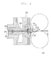
- the pneumatic spinning device 9 includes a nozzle block (nozzle member) 30 and a hollow guide shaft body 34.
- the nozzle block 30 includes a fiber guide 31, a spinning chamber 32, and a first nozzle 33.
- the hollow guide shaft body 34 includes a yarn passage 35 and a second nozzle 36. Each section of the pneumatic spinning device 9 is controlled by the unit controller.
- the fiber guide 31 is a member adapted to guide the fiber bundle 8 drafted by the draft device 7 into the pneumatic spinning device 9.
- the fiber guide 31 is provided with a fiber introducing port 31a and a guide needle 31b.
- the fiber bundle 8 drafted by the draft device 7 is introduced from the fiber introducing port 31a, and guided into the spinning chamber 32 so as to be wound around the guide needle 31b.
- Whirling airflow is generated in the spinning chamber 32 by injecting air from the first nozzle 33 into the spinning chamber 32. The whirling airflow thereby acts on the fiber bundle 8 in the spinning chamber 32.
- the hollow guide shaft body 34 is a cylindrical member, and the yarn passage 35 is formed inside the hollow guide shaft body 34.
- Whirling airflow is generated in the yarn passage 35 by injecting air from the second nozzle 36 into the yarn passage 35.
- a direction of the whirling airflow generated by injecting the air from the second nozzle 36 is opposite to a direction of the whirling airflow generated by injecting the air from the first nozzle 33.
- the whirling airflow is generated by injecting the air from both the first nozzle 33 and the second nozzle 36.
- the fiber bundle 8 drafted by the draft device 7 is guided into the pneumatic spinning device 9 by the fiber guide 31.
- the air injected from the first nozzle 33 flows in a feeding direction of the fiber bundle 8 while whirling.
- the fiber bundle 8 is thereby fed to the hollow guide shaft body 34 in a loose false-twisted state.
- the whirling airflow flows towards the downstream in the yarn passage 35.
- the fiber bundle 8 is thereby fed towards the downstream of the yarn passage 35.
- a direction of the whirling airflow generated in the yarn passage 35 is opposite to a direction of the whirling airflow in the spinning chamber 32, and hence the fiber bundle 8 is discharged from the hollow guide shaft body 34 while being spun into a fasciated yarn by a known spinning method described in Japanese Unexamined Patent Publication No. 2011-38210 and the like.
- the normal spinning is carried out after the yarn discharge spinning.
- the air is injected only from the first nozzle 33 when carrying out the normal spinning.
- Back ends of the fibers of the fiber bundle 8 supplied from the draft device 7 are swung around a periphery of a distal end of the hollow guide shaft body 34 by the air injected from the first nozzle 33. Accordingly, twists are applied to the fiber bundle 8 to produce the spun yarn 10.
- the spun yarn 10 is passed through the yarn passage 35 of the hollow guide shaft body 34, and fed to an outside of the pneumatic spinning device 9 from a downstream yarn exit (not illustrated).
- twists can be applied to the fiber bundle 8 during the yarn discharge spinning and the normal spinning to produce the spun yarn 10.
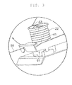
- a first guide 61 (guide member, FIG. 3 ) adapted to guide the spun yarn 10 is arranged downstream of the pneumatic spinning device 9.
- the first guide 61 guides the spun yarn 10 to the yarn accumulating device 22.
- the first guide 61 is movable to guide the spun yarn 10 towards the yarn accumulating device 22 when performing a yarn joining operation and the like.
- the yarn accumulating device 22 is arranged downstream of the first guide 61.
- the yarn accumulating device 22 includes a yarn accumulating roller 41, an electric motor 42 for rotatably driving the yarn accumulating roller 41, a yarn hooking member 43, and a yarn amount detecting sensor (detecting section) 44.
- the spun yarn 10 is temporarily accumulated by being wound around an outer peripheral surface of the yarn accumulating roller 41.
- the yarn hooking member 43 is attached to a downstream end of the yarn accumulating roller 41.
- the yarn hooking member 43 is supported in a relatively rotatable manner with respect to the yarn accumulating roller 41.
- a permanent magnet is attached to one of the yarn hooking member 43 and the yarn accumulating roller 41, and a magnetic hysteresis material is attached to the other of the yarn hooking member 43 and the yarn accumulating roller 41.
- Such magnetic means generates a torque against the relative rotation of the yarn hooking member 43 with respect to the yarn accumulating roller 41.
- the yarn hooking member 43 relatively rotates with respect to the yarn accumulating roller 41, and the spun yarn 10 wound around the yarn accumulating roller 41 can be unwound.
- the yarn hooking member 43 integrally rotates with the yarn accumulating roller 41, and the spun yarn 10 is accumulated on the yarn accumulating roller 41.
- the yarn accumulating device 22 operates to unwind the spun yarn 10 when the yarn tension at the downstream is increased, and stop the unwinding of the spun yarn 10 when the yarn tension is decreased (when the spun yarn 10 starts to slacken).
- the yarn accumulating device 22 can resolve the slackening of the spun yarn 10 and apply an appropriate tension to the spun yarn 10.
- the yarn hooking member 43 operates to absorb fluctuation in the tension applied to the spun yarn 10 between the yarn accumulating device 22 and the winding section 26, and the fluctuation in the tension can be prevented from affecting the spun yarn 10 from the pneumatic spinning device 9 to the yarn accumulating device 22.
- the yarn amount detecting sensor 44 is an optical sensor, and is adapted to detect whether or not an accumulated amount of the spun yarn 10 on the yarn accumulating device 22 is greater than or equal to a predetermined amount.
- a second guide 62 adapted to restrict movement of the spun yarn 10 unwound from the yarn accumulating roller 41 is arranged downstream of the yarn accumulating roller 41.
- the yarn joining device 23 is arranged downstream of the second guide 62.
- the yarn joining device 23 carries out the yarn joining operation of a spun yarn 10 (first yarn) from the pneumatic spinning device 9 and a spun yarn 10 (second yarn) from the package 50 when the spun yarn 10 between the pneumatic spinning device 9 and the package 50 is disconnected for some reason.
- the yarn joining device 23 is a splicer device adapted to twist yarn ends with whirling airflow generated by compressed air.
- the yarn joining device 23 is not limited to the splicer device, and for example, a mechanical knotter and the like may be adopted.
- the spinning unit 2 includes a catching and guiding device adapted to guide the spun yarn 10 to the yarn joining device 23.
- the catching and guiding device is configured by a first catching and guiding device 27 adapted to guide the first yarn, and a second catching and guiding device 28 adapted to guide the second yarn to the yarn joining device 23.
- a basal end portion of the first catching and guiding device 27 is swingably supported, and the first catching and guiding device 27 can be swung vertically with this base portion as a center of swing.
- the first catching and guiding device 27 is formed in a hollow form, and is connected to a blower (not illustrated) so as to be able to generate suction airflow.
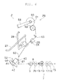
- the first catching and guiding device 27 is swung downward to catch a yarn end of the first yarn (see FIG. 4 ). After catching the first yarn, the first catching and guiding device 27 is swung upward to guide the first yarn to the yarn joining device 23.
- the first catching and guiding device 27 can catch and guide the yarn end of the first yarn fed from the pneumatic spinning device 9.
- the first catching and guiding device 27 may not have a twist applying function.
- the second nozzle 36 functions to apply twists to the fiber bundle 8 during the yarn discharge spinning.
- the first catching and guiding device 27 may have the twist applying function.
- a basal end portion of the second catching and guiding device 28 is swingably supported, and the second catching and guiding device 28 can be swung vertically with this base portion as a center of swing.
- the second catching and guiding device 28 is also formed in a hollow form, and is connected to a blower (not illustrated) so as to be able to generate suction airflow.
- the second catching and guiding device 28 is swung upward to catch a yarn end of the second yarn (see a chain line in FIG. 1 ). After catching the second yarn, the second catching and guiding device 28 is swung downward to guide the second yarn to the yarn joining device 23.
- the yarn joining device 23 is driven while the first yarn and the second yarn are being guided to the yarn joining device 23, so that the first yarn and the second yarn are joined and the spun yarn 10 is connected between the pneumatic spinning device 9 and the package 50. The winding of the spun yarn 10 into the package 50 thus can be resumed.
- the yarn monitoring device 25 is arranged downstream of the yarn joining device 23.
- the yarn monitoring device 25 monitors a thickness of the travelling spun yarn 10 with a capacitance sensor (not illustrated).
- a yarn defect of the spun yarn 10 area where abnormality is found in thickness or the like of the spun yarn 10.
- the yarn monitoring device 25 transmits a yarn defect detection signal to a unit controller.
- the unit controller drives a cutter 24 (yarn cutting device) arranged in proximity to the yarn monitoring device 25 to cut the spun yarn 10.
- the yarn monitoring device 25 is not limited to the capacitance sensor and may be a light transmissive sensor to monitor the thickness of the spun yarn 10. Foreign substances contained in the spun yarn 10 may be monitored as the yarn defect.
- the winding section 26 is arranged downstream of the yarn accumulating device 22.
- the winding section 26 includes a cradle arm 52 and a winding drum 53.
- a yarn path from the yarn accumulating device 22 to the winding section 26 is bent and guided by a downstream guide 63.
- the cradle arm 52 can rotatably support a winding tube 51 for winding the spun yarn 10.
- the cradle arm 52 is swingable with a basal end portion thereof as the center of swing. Thus, even if the spun yarn 10 is wound around the winding tube 51 and a diameter of the package 50 is increased, the winding of the spun yarn 10 can be appropriately continued.
- the winding drum 53 rotates while making contact with an outer peripheral surface of the winding tube 51 or an outer peripheral surface of the package 50.
- a traverse groove (not illustrated) is formed on an outer peripheral surface of the winding drum 53, and the spun yarn 10 is traversed by the traverse groove at a predetermined width. Accordingly, the winding section 26 can wind the spun yarn 10 around the winding tube 51 while traversing the spun yarn 10 to form the package 50.
- FIGS. 4 to 6 the next process is illustrated to be carried out after one process is completed to facilitate the understanding of the drawings, but the next process may be started before one process is completed. Note that a similar process is carried out also in a case of starting the spinning to start the winding of the spun yarn 10 around a new winding tube 51 without carrying out the yarn joining operation.
- the spun yarn 10 becomes disconnected after yarn breakage occurs during the winding of the package 50, or after the spun yarn 10 is cut by the cutter 24.
- the winding section 26 stops the winding of the package 50
- the draft device 7 stops the drafting of the fiber bundle 8
- the pneumatic spinning device 9 stops the spinning.
- the first guide 61 moves to a position away from the yarn accumulating device 22.
- the second catching and guiding device 28 is swung upward to catch the second yarn. Thereafter, the second catching and guiding device 28 is swung downward while keeping the caught second yarn to guide the second yarn to a position where the yarn joining operation can be carried out by the yarn joining device 23.
- the first catching and guiding device 27 is swung downward to move to a position where the first yarn can be caught.
- the drafting of the fiber bundle 8 by the draft device 7 is then resumed and the yarn discharge spinning by the pneumatic spinning device 9 is carried out.
- the first yarn is sucked and caught by the first catching and guiding device 27.
- the first catching and guiding device 27 is swung upward while continuing sucking of the first yarn to guide the first yarn to a position where the yarn joining operation can be carried out by the yarn joining device 23.
- the first yarn and the second yarn are thereby guided to the yarn joining device 23, as illustrated in FIG. 5 .
- the pneumatic spinning device 9 of the present embodiment continues to inject the airflow from the second nozzle 36 until the spun yarn 10 is wound by the yarn accumulating device 22 (detailed control will be described later).
- the first guide 61 moves to approach the yarn accumulating device 22 (see FIG. 6 ).
- the first guide 61 thus guides the spun yarn 10 to proximity of the yarn accumulating device 22 while catching the spun yarn 10.
- the spun yarn 10 thus can be hooked to the yarn hooking member 43 of the yarn accumulating device 22. Therefore, the spun yarn 10 can be started to be wound around the yarn accumulating roller 41. After the spun yarn 10 is wound around the yarn accumulating roller 41, the pneumatic spinning device 9 stops the injection of the air from the second nozzle 36. Thereafter, when the yarn joining operation is completed, the stopped winding drum 53 and the like are again driven. The winding of the package 50 thus can be resumed.
- a spinning condition in which the yarn breakage and the clogging of the fibers in the pneumatic spinning device 9 are less likely to occur is set for the yarn discharge spinning, and the pneumatic spinning device 9 carries out the yarn discharge spinning under such a spinning condition.
- the unit controller determines whether or not the spun yarn 10 is wound in the yarn accumulating device 22 (yarn accumulating roller 41) (step S102). This determination is made, for example, based on a timing at which a process of causing the first guide 61 to approach the yarn accumulating device 22 is carried out or a timing at which the yarn amount detecting sensor 44 detected the spun yarn 10 greater than or equal to the predetermined amount.
- the unit controller determines that the spun yarn 10 is wound around the yarn accumulating roller 41.
- the spun yarn 10 may be assumed as being wound around the yarn accumulating roller 41 when a predetermined time or more has elapsed from the start of the yarn discharge spinning.
- the unit controller stops the injection of the air from the second nozzle 36 and starts the normal spinning (step S103, time T2 of FIG. 8 ).
- time T1 of FIG. 8 when the spun yarn 10 starts to be wound around the yarn accumulating roller 41, the air is still injected from the second nozzle 36.
- the spun yarn 10 is wound (mechanically pulled) around the yarn accumulating roller 41, the spun yarn 10 is stably pulled out from the pneumatic spinning device 9, and hence the injection of the air from the second nozzle 36 may be stopped.
- the unit controller then changes the spinning condition (at least one of spinning speed, draft ratio, and yarn count) after the termination of the yarn discharge spinning in accordance with the requested package 50 (step S104, time T2 of FIG. 8 ). If the spinning condition is not required to be changed for the yarn discharge spinning and for the normal spinning, the normal spinning is continued under the condition for the yarn discharge spinning. While the yarn discharge spinning is being carried out, the spinning condition is not changed. The above condition is fixed until the spun yarn 10 is wound around the yarn accumulating roller 41, and thus the yarn breakage, the clogging of the fibers, or the like can be prevented.
- the delivery roller is arranged immediately downstream of the pneumatic spinning device in Patent Documents 1 and 2. Therefore, the spun yarn is pulled out from the pneumatic spinning device by the delivery roller immediately after the yarn discharge spinning is started. In other words, the spun yarn is mechanically pulled out even during the yarn discharge spinning. Thus, the clogging of the fibers in the pneumatic spinning device, and the like are less likely to occur even if the spinning condition is changed in a middle of the yarn discharge spinning.
- the spinning machine of the present embodiment is a delivery roller-less spinning machine, and thus the spun yarn 10 pulled out from the pneumatic spinning device 9 is not mechanically pulled out at first and is merely sucked and caught by the first catching and guiding device 27. Therefore, the clogging of the fibers in the pneumatic spinning device 9 may occur by merely changing the spinning condition during the yarn discharge spinning, for example. Properties of the spun yarn to be handled during the yarn discharge spinning thus differ between Patent Documents 1 and 2, and the present application.
- the spinning machine of the present embodiment includes the pneumatic spinning device 9 and the yarn accumulating device 22.
- the pneumatic spinning device 9 includes the nozzle block 30 and the hollow guide shaft body 34, the nozzle block 30 including the first nozzle 33 through which air passes to be injected to generate whirling airflow in the spinning chamber 32, and the hollow guide shaft body 34 being arranged downstream in a fiber travelling direction than the nozzle block 30 and including the second nozzle 36 through which air passes to be injected to generate whirling airflow for sucking a fiber bundle 8 from the spinning chamber 32.
- the yarn accumulating device 22 accumulates the spun yarn 10 produced by the pneumatic spinning device 9 while pulling out the spun yarn 10.
- the air is injected from the first nozzle 33 and the second nozzle 36 at least at an instance when the spun yarn 10 starts being wound around the yarn accumulating roller 41 in the yarn discharge spinning.
- the first catching and guiding device 27 may not have the twist applying function.
- the injection of the air from the second nozzle 36 is stopped while maintaining the injection of the air from the first nozzle 33.
- the spun yarn 10 After the spun yarn 10 is wound around the yarn accumulating roller 41, the spun yarn 10 is stably pulled out by the yarn accumulating roller 41, and thus, the injection of the air from the second nozzle 36 is not necessary. Thus, a structure excellent in energy saving property can be realized by stopping the injection of the air from the second nozzle 36.
- a condition of at least one of a spinning speed, a draft ratio, and a yarn count is fixed.
- the amount of fiber bundle 8 to be processed by the pneumatic spinning device 9 changes.
- the yarn breakage or the clogging of the fibers in the pneumatic spinning device 9 may occur.
- the above condition is fixed until the spun yarn 10 is wound around the yarn accumulating roller 41, so that the yarn breakage, the clogging of the fibers, or the like can be prevented.
- the condition of at least one of the spinning speed, the draft ratio, and the yarn count is changed.
- the spun yarn 10 may be produced by changing the condition to the condition complying with the demand.
- the spinning machine of the present embodiment may further include the first guide 61 adapted to guide the spun yarn 10 produced by the pneumatic spinning device 9 to the yarn accumulating roller 41 such that the spun yarn 10 starts being wound around the yarn accumulating roller 41 at the time of the yarn discharge spinning.
- the injection of the air from the second nozzle 36 is stopped in accordance with a timing at which the first guide 61 guided the spun yarn 10 to the yarn accumulating roller 41 at the time of the yarn discharge spinning.
- the injection of the air from the second nozzle 36 can be stopped without providing a dedicated detecting section for detecting a timing at which the spun yarn 10 is stably pulled out by the yarn accumulating roller 41.
- the spinning machine of the present embodiment further includes the yarn amount detecting sensor 44 adapted to detect the spun yarn 10 accumulated around the yarn accumulating roller 41.
- the injection of the air from the second nozzle 36 is stopped in accordance with a timing at which the yarn amount detecting sensor 44 detected the spun yarn 10 during the yarn discharge spinning.
- the timing at which the spun yarn 10 is stably pulled out by the yarn accumulating roller 41 can be reliably detected.
- the guide needle 31b may be omitted, and a downstream end of the fiber guide 31 may function as the guide needle 31b.
- a operation cart that can move among the spinning units 2 may be arranged and the operation cart may carry out the yarn joining operation.
Landscapes
- Engineering & Computer Science (AREA)
- Mechanical Engineering (AREA)
- Textile Engineering (AREA)
- Spinning Or Twisting Of Yarns (AREA)
Applications Claiming Priority (1)
| Application Number | Priority Date | Filing Date | Title |
|---|---|---|---|
| JP2014141879A JP2016017254A (ja) | 2014-07-10 | 2014-07-10 | 紡績機及び紡績方法 |
Publications (3)
| Publication Number | Publication Date |
|---|---|
| EP2966200A2 true EP2966200A2 (de) | 2016-01-13 |
| EP2966200A3 EP2966200A3 (de) | 2016-03-09 |
| EP2966200B1 EP2966200B1 (de) | 2019-03-13 |
Family
ID=53269378
Family Applications (1)
| Application Number | Title | Priority Date | Filing Date |
|---|---|---|---|
| EP15170031.7A Not-in-force EP2966200B1 (de) | 2014-07-10 | 2015-06-01 | Spinnmaschine und spinnverfahren |
Country Status (3)
| Country | Link |
|---|---|
| EP (1) | EP2966200B1 (de) |
| JP (1) | JP2016017254A (de) |
| CN (1) | CN105256417B (de) |
Cited By (3)
| Publication number | Priority date | Publication date | Assignee | Title |
|---|---|---|---|---|
| EP3438333A1 (de) * | 2017-08-02 | 2019-02-06 | Murata Machinery, Ltd. | Luftspinnmaschine |
| CN114645340A (zh) * | 2020-12-18 | 2022-06-21 | 卓郎智能技术有限公司 | 气流纺纱机的工位以及导纱件 |
| DE102023111660A1 (de) | 2023-05-04 | 2024-11-07 | Maschinenfabrik Rieter Ag | Luftspinnmaschine und Anspinnverfahren |
Families Citing this family (4)
| Publication number | Priority date | Publication date | Assignee | Title |
|---|---|---|---|---|
| JP2019104596A (ja) * | 2017-12-12 | 2019-06-27 | 村田機械株式会社 | 糸巻取機及び糸巻取方法 |
| IT201900001195A1 (it) * | 2019-01-28 | 2020-07-28 | Savio Macch Tessili Spa | Apparato di filatura, in particolare ad aria, con regolazione in continuo di un sistema di accumulo filo e relativo metodo di regolazione in continuo di un sistema di accumulo filo in un apparato di filatura |
| JP7286500B2 (ja) * | 2019-09-25 | 2023-06-05 | Tmtマシナリー株式会社 | 紡糸巻取設備 |
| JP2021193225A (ja) * | 2020-06-09 | 2021-12-23 | 村田機械株式会社 | 空気紡績機 |
Citations (3)
| Publication number | Priority date | Publication date | Assignee | Title |
|---|---|---|---|---|
| JP2001146646A (ja) | 1999-11-15 | 2001-05-29 | Murata Mach Ltd | 紡績方法 |
| JP2003278035A (ja) | 2002-03-18 | 2003-10-02 | Murata Mach Ltd | 紡績方法及びその装置 |
| JP2011038210A (ja) | 2009-08-11 | 2011-02-24 | Murata Machinery Ltd | 空気紡績装置及びこの空気紡績装置を備える紡績機 |
Family Cites Families (6)
| Publication number | Priority date | Publication date | Assignee | Title |
|---|---|---|---|---|
| JPH07126935A (ja) * | 1993-10-29 | 1995-05-16 | Murata Mach Ltd | 紡績機の糸継ぎ方法 |
| JP2658901B2 (ja) * | 1994-09-05 | 1997-09-30 | 村田機械株式会社 | 紡績装置 |
| JP2013002023A (ja) * | 2011-06-20 | 2013-01-07 | Murata Mach Ltd | 中空ガイド軸体ユニット、空気紡績装置及び紡績機 |
| JP2013067882A (ja) * | 2011-09-21 | 2013-04-18 | Murata Mach Ltd | 糸巻取機、及び紡績糸の製造方法 |
| CN104395269A (zh) * | 2012-06-29 | 2015-03-04 | 赫多特普索化工设备公司 | 通过加氢净化原料气 |
| JP2015101805A (ja) * | 2013-11-25 | 2015-06-04 | 村田機械株式会社 | 空気紡績装置及び紡績機 |
-
2014
- 2014-07-10 JP JP2014141879A patent/JP2016017254A/ja active Pending
-
2015
- 2015-06-01 EP EP15170031.7A patent/EP2966200B1/de not_active Not-in-force
- 2015-06-25 CN CN201510357773.XA patent/CN105256417B/zh active Active
Patent Citations (3)
| Publication number | Priority date | Publication date | Assignee | Title |
|---|---|---|---|---|
| JP2001146646A (ja) | 1999-11-15 | 2001-05-29 | Murata Mach Ltd | 紡績方法 |
| JP2003278035A (ja) | 2002-03-18 | 2003-10-02 | Murata Mach Ltd | 紡績方法及びその装置 |
| JP2011038210A (ja) | 2009-08-11 | 2011-02-24 | Murata Machinery Ltd | 空気紡績装置及びこの空気紡績装置を備える紡績機 |
Cited By (4)
| Publication number | Priority date | Publication date | Assignee | Title |
|---|---|---|---|---|
| EP3438333A1 (de) * | 2017-08-02 | 2019-02-06 | Murata Machinery, Ltd. | Luftspinnmaschine |
| CN114645340A (zh) * | 2020-12-18 | 2022-06-21 | 卓郎智能技术有限公司 | 气流纺纱机的工位以及导纱件 |
| CN114645340B (zh) * | 2020-12-18 | 2023-12-22 | 卓郎智能技术有限公司 | 气流纺纱机的工位以及导纱件 |
| DE102023111660A1 (de) | 2023-05-04 | 2024-11-07 | Maschinenfabrik Rieter Ag | Luftspinnmaschine und Anspinnverfahren |
Also Published As
| Publication number | Publication date |
|---|---|
| CN105256417A (zh) | 2016-01-20 |
| EP2966200B1 (de) | 2019-03-13 |
| CN105256417B (zh) | 2018-11-27 |
| JP2016017254A (ja) | 2016-02-01 |
| EP2966200A3 (de) | 2016-03-09 |
Similar Documents
| Publication | Publication Date | Title |
|---|---|---|
| EP2966200B1 (de) | Spinnmaschine und spinnverfahren | |
| EP2302115B1 (de) | Spinnmaschinesteuerungsverfahren | |
| EP2727870B1 (de) | Garnwickelmaschine und Garnwickelverfahren | |
| EP2213773B2 (de) | Vorrichtung zur Aufnahme des Garnendes und damit ausgerüstete Spinnmaschine | |
| EP2573232A2 (de) | Vorrichtung zur Verbindung eines Garns und Garnwickelmaschine und Einheit damit | |
| EP3025995B1 (de) | Garnwicklungsmaschine | |
| CN106567170B (zh) | 纺织机以及控制装置 | |
| CN110158207B (zh) | 空气纺纱机和空气纺纱方法 | |
| EP3072840B1 (de) | Garnwickelmaschine und garnwickelverfahren | |
| JP2013063839A (ja) | 糸巻取機及び糸巻取ユニット | |
| EP2573223A2 (de) | Pneumatische Spinnmaschine, Spinneinheit, Spinnmaschine und pneumatisches Spinnverfahren | |
| EP2977493B1 (de) | Spinnmaschine und spinnverfahren | |
| JP2014125714A (ja) | 紡績機 | |
| CN108286093B (zh) | 一种纺纱机 | |
| EP2862826A1 (de) | Garnwickelmaschine | |
| EP3040458B1 (de) | Core-garnzuführvorrichtung, spinnmaschine und verfahren zum zuführen von core-garn | |
| EP2949793B1 (de) | Spinnmaschine und spinnverfahren | |
| EP3363757A1 (de) | Garnverarbeitungsmaschine | |
| EP3095742A1 (de) | Garnwicklungsmaschine | |
| JP2017071865A (ja) | 紡績機 | |
| EP3421650A1 (de) | Luftspinnmaschine | |
| CN115072478A (zh) | 纺纱机 | |
| EP2966199B1 (de) | Spinnmaschine und spinnverfahren | |
| EP2949794B1 (de) | Spinnmaschine und spinnverfahren | |
| JP2022085990A (ja) | 紡績機及び紡績方法 |
Legal Events
| Date | Code | Title | Description |
|---|---|---|---|
| PUAI | Public reference made under article 153(3) epc to a published international application that has entered the european phase |
Free format text: ORIGINAL CODE: 0009012 |
|
| AK | Designated contracting states |
Kind code of ref document: A2 Designated state(s): AL AT BE BG CH CY CZ DE DK EE ES FI FR GB GR HR HU IE IS IT LI LT LU LV MC MK MT NL NO PL PT RO RS SE SI SK SM TR |
|
| AX | Request for extension of the european patent |
Extension state: BA ME |
|
| PUAL | Search report despatched |
Free format text: ORIGINAL CODE: 0009013 |
|
| AK | Designated contracting states |
Kind code of ref document: A3 Designated state(s): AL AT BE BG CH CY CZ DE DK EE ES FI FR GB GR HR HU IE IS IT LI LT LU LV MC MK MT NL NO PL PT RO RS SE SI SK SM TR |
|
| AX | Request for extension of the european patent |
Extension state: BA ME |
|
| RIC1 | Information provided on ipc code assigned before grant |
Ipc: D01H 13/10 20060101ALI20160129BHEP Ipc: D01H 1/115 20060101AFI20160129BHEP Ipc: D01H 13/04 20060101ALI20160129BHEP |
|
| 17P | Request for examination filed |
Effective date: 20160727 |
|
| RBV | Designated contracting states (corrected) |
Designated state(s): AL AT BE BG CH CY CZ DE DK EE ES FI FR GB GR HR HU IE IS IT LI LT LU LV MC MK MT NL NO PL PT RO RS SE SI SK SM TR |
|
| RIC1 | Information provided on ipc code assigned before grant |
Ipc: D01H 13/04 20060101ALI20180717BHEP Ipc: D01H 1/115 20060101AFI20180717BHEP Ipc: D01H 13/10 20060101ALI20180717BHEP |
|
| GRAP | Despatch of communication of intention to grant a patent |
Free format text: ORIGINAL CODE: EPIDOSNIGR1 |
|
| STAA | Information on the status of an ep patent application or granted ep patent |
Free format text: STATUS: GRANT OF PATENT IS INTENDED |
|
| INTG | Intention to grant announced |
Effective date: 20180924 |
|
| GRAS | Grant fee paid |
Free format text: ORIGINAL CODE: EPIDOSNIGR3 |
|
| GRAA | (expected) grant |
Free format text: ORIGINAL CODE: 0009210 |
|
| STAA | Information on the status of an ep patent application or granted ep patent |
Free format text: STATUS: THE PATENT HAS BEEN GRANTED |
|
| AK | Designated contracting states |
Kind code of ref document: B1 Designated state(s): AL AT BE BG CH CY CZ DE DK EE ES FI FR GB GR HR HU IE IS IT LI LT LU LV MC MK MT NL NO PL PT RO RS SE SI SK SM TR |
|
| REG | Reference to a national code |
Ref country code: GB Ref legal event code: FG4D |
|
| REG | Reference to a national code |
Ref country code: CH Ref legal event code: EP Ref country code: AT Ref legal event code: REF Ref document number: 1107777 Country of ref document: AT Kind code of ref document: T Effective date: 20190315 |
|
| REG | Reference to a national code |
Ref country code: IE Ref legal event code: FG4D |
|
| REG | Reference to a national code |
Ref country code: DE Ref legal event code: R096 Ref document number: 602015026176 Country of ref document: DE |
|
| REG | Reference to a national code |
Ref country code: CH Ref legal event code: NV Representative=s name: BOVARD AG PATENT- UND MARKENANWAELTE, CH |
|
| REG | Reference to a national code |
Ref country code: NL Ref legal event code: MP Effective date: 20190313 |
|
| REG | Reference to a national code |
Ref country code: LT Ref legal event code: MG4D |
|
| PG25 | Lapsed in a contracting state [announced via postgrant information from national office to epo] |
Ref country code: SE Free format text: LAPSE BECAUSE OF FAILURE TO SUBMIT A TRANSLATION OF THE DESCRIPTION OR TO PAY THE FEE WITHIN THE PRESCRIBED TIME-LIMIT Effective date: 20190313 Ref country code: NO Free format text: LAPSE BECAUSE OF FAILURE TO SUBMIT A TRANSLATION OF THE DESCRIPTION OR TO PAY THE FEE WITHIN THE PRESCRIBED TIME-LIMIT Effective date: 20190613 Ref country code: FI Free format text: LAPSE BECAUSE OF FAILURE TO SUBMIT A TRANSLATION OF THE DESCRIPTION OR TO PAY THE FEE WITHIN THE PRESCRIBED TIME-LIMIT Effective date: 20190313 Ref country code: LT Free format text: LAPSE BECAUSE OF FAILURE TO SUBMIT A TRANSLATION OF THE DESCRIPTION OR TO PAY THE FEE WITHIN THE PRESCRIBED TIME-LIMIT Effective date: 20190313 |
|
| PG25 | Lapsed in a contracting state [announced via postgrant information from national office to epo] |
Ref country code: GR Free format text: LAPSE BECAUSE OF FAILURE TO SUBMIT A TRANSLATION OF THE DESCRIPTION OR TO PAY THE FEE WITHIN THE PRESCRIBED TIME-LIMIT Effective date: 20190614 Ref country code: BG Free format text: LAPSE BECAUSE OF FAILURE TO SUBMIT A TRANSLATION OF THE DESCRIPTION OR TO PAY THE FEE WITHIN THE PRESCRIBED TIME-LIMIT Effective date: 20190613 Ref country code: HR Free format text: LAPSE BECAUSE OF FAILURE TO SUBMIT A TRANSLATION OF THE DESCRIPTION OR TO PAY THE FEE WITHIN THE PRESCRIBED TIME-LIMIT Effective date: 20190313 Ref country code: LV Free format text: LAPSE BECAUSE OF FAILURE TO SUBMIT A TRANSLATION OF THE DESCRIPTION OR TO PAY THE FEE WITHIN THE PRESCRIBED TIME-LIMIT Effective date: 20190313 Ref country code: NL Free format text: LAPSE BECAUSE OF FAILURE TO SUBMIT A TRANSLATION OF THE DESCRIPTION OR TO PAY THE FEE WITHIN THE PRESCRIBED TIME-LIMIT Effective date: 20190313 Ref country code: RS Free format text: LAPSE BECAUSE OF FAILURE TO SUBMIT A TRANSLATION OF THE DESCRIPTION OR TO PAY THE FEE WITHIN THE PRESCRIBED TIME-LIMIT Effective date: 20190313 |
|
| REG | Reference to a national code |
Ref country code: AT Ref legal event code: MK05 Ref document number: 1107777 Country of ref document: AT Kind code of ref document: T Effective date: 20190313 |
|
| PG25 | Lapsed in a contracting state [announced via postgrant information from national office to epo] |
Ref country code: SK Free format text: LAPSE BECAUSE OF FAILURE TO SUBMIT A TRANSLATION OF THE DESCRIPTION OR TO PAY THE FEE WITHIN THE PRESCRIBED TIME-LIMIT Effective date: 20190313 Ref country code: IT Free format text: LAPSE BECAUSE OF FAILURE TO SUBMIT A TRANSLATION OF THE DESCRIPTION OR TO PAY THE FEE WITHIN THE PRESCRIBED TIME-LIMIT Effective date: 20190313 Ref country code: EE Free format text: LAPSE BECAUSE OF FAILURE TO SUBMIT A TRANSLATION OF THE DESCRIPTION OR TO PAY THE FEE WITHIN THE PRESCRIBED TIME-LIMIT Effective date: 20190313 Ref country code: ES Free format text: LAPSE BECAUSE OF FAILURE TO SUBMIT A TRANSLATION OF THE DESCRIPTION OR TO PAY THE FEE WITHIN THE PRESCRIBED TIME-LIMIT Effective date: 20190313 Ref country code: RO Free format text: LAPSE BECAUSE OF FAILURE TO SUBMIT A TRANSLATION OF THE DESCRIPTION OR TO PAY THE FEE WITHIN THE PRESCRIBED TIME-LIMIT Effective date: 20190313 Ref country code: PT Free format text: LAPSE BECAUSE OF FAILURE TO SUBMIT A TRANSLATION OF THE DESCRIPTION OR TO PAY THE FEE WITHIN THE PRESCRIBED TIME-LIMIT Effective date: 20190713 Ref country code: AL Free format text: LAPSE BECAUSE OF FAILURE TO SUBMIT A TRANSLATION OF THE DESCRIPTION OR TO PAY THE FEE WITHIN THE PRESCRIBED TIME-LIMIT Effective date: 20190313 |
|
| PG25 | Lapsed in a contracting state [announced via postgrant information from national office to epo] |
Ref country code: PL Free format text: LAPSE BECAUSE OF FAILURE TO SUBMIT A TRANSLATION OF THE DESCRIPTION OR TO PAY THE FEE WITHIN THE PRESCRIBED TIME-LIMIT Effective date: 20190313 Ref country code: SM Free format text: LAPSE BECAUSE OF FAILURE TO SUBMIT A TRANSLATION OF THE DESCRIPTION OR TO PAY THE FEE WITHIN THE PRESCRIBED TIME-LIMIT Effective date: 20190313 |
|
| REG | Reference to a national code |
Ref country code: DE Ref legal event code: R097 Ref document number: 602015026176 Country of ref document: DE |
|
| PG25 | Lapsed in a contracting state [announced via postgrant information from national office to epo] |
Ref country code: AT Free format text: LAPSE BECAUSE OF FAILURE TO SUBMIT A TRANSLATION OF THE DESCRIPTION OR TO PAY THE FEE WITHIN THE PRESCRIBED TIME-LIMIT Effective date: 20190313 Ref country code: IS Free format text: LAPSE BECAUSE OF FAILURE TO SUBMIT A TRANSLATION OF THE DESCRIPTION OR TO PAY THE FEE WITHIN THE PRESCRIBED TIME-LIMIT Effective date: 20190713 |
|
| PLBE | No opposition filed within time limit |
Free format text: ORIGINAL CODE: 0009261 |
|
| STAA | Information on the status of an ep patent application or granted ep patent |
Free format text: STATUS: NO OPPOSITION FILED WITHIN TIME LIMIT |
|
| PG25 | Lapsed in a contracting state [announced via postgrant information from national office to epo] |
Ref country code: DK Free format text: LAPSE BECAUSE OF FAILURE TO SUBMIT A TRANSLATION OF THE DESCRIPTION OR TO PAY THE FEE WITHIN THE PRESCRIBED TIME-LIMIT Effective date: 20190313 Ref country code: MC Free format text: LAPSE BECAUSE OF FAILURE TO SUBMIT A TRANSLATION OF THE DESCRIPTION OR TO PAY THE FEE WITHIN THE PRESCRIBED TIME-LIMIT Effective date: 20190313 |
|
| 26N | No opposition filed |
Effective date: 20191216 |
|
| GBPC | Gb: european patent ceased through non-payment of renewal fee |
Effective date: 20190613 |
|
| PG25 | Lapsed in a contracting state [announced via postgrant information from national office to epo] |
Ref country code: SI Free format text: LAPSE BECAUSE OF FAILURE TO SUBMIT A TRANSLATION OF THE DESCRIPTION OR TO PAY THE FEE WITHIN THE PRESCRIBED TIME-LIMIT Effective date: 20190313 |
|
| REG | Reference to a national code |
Ref country code: BE Ref legal event code: MM Effective date: 20190630 |
|
| PG25 | Lapsed in a contracting state [announced via postgrant information from national office to epo] |
Ref country code: TR Free format text: LAPSE BECAUSE OF FAILURE TO SUBMIT A TRANSLATION OF THE DESCRIPTION OR TO PAY THE FEE WITHIN THE PRESCRIBED TIME-LIMIT Effective date: 20190313 |
|
| PG25 | Lapsed in a contracting state [announced via postgrant information from national office to epo] |
Ref country code: IE Free format text: LAPSE BECAUSE OF NON-PAYMENT OF DUE FEES Effective date: 20190601 Ref country code: GB Free format text: LAPSE BECAUSE OF NON-PAYMENT OF DUE FEES Effective date: 20190613 |
|
| PG25 | Lapsed in a contracting state [announced via postgrant information from national office to epo] |
Ref country code: LU Free format text: LAPSE BECAUSE OF NON-PAYMENT OF DUE FEES Effective date: 20190601 Ref country code: BE Free format text: LAPSE BECAUSE OF NON-PAYMENT OF DUE FEES Effective date: 20190630 |
|
| PG25 | Lapsed in a contracting state [announced via postgrant information from national office to epo] |
Ref country code: FR Free format text: LAPSE BECAUSE OF NON-PAYMENT OF DUE FEES Effective date: 20190630 |
|
| PGFP | Annual fee paid to national office [announced via postgrant information from national office to epo] |
Ref country code: CH Payment date: 20200618 Year of fee payment: 6 Ref country code: DE Payment date: 20200618 Year of fee payment: 6 Ref country code: CZ Payment date: 20200528 Year of fee payment: 6 |
|
| PG25 | Lapsed in a contracting state [announced via postgrant information from national office to epo] |
Ref country code: CY Free format text: LAPSE BECAUSE OF FAILURE TO SUBMIT A TRANSLATION OF THE DESCRIPTION OR TO PAY THE FEE WITHIN THE PRESCRIBED TIME-LIMIT Effective date: 20190313 |
|
| PG25 | Lapsed in a contracting state [announced via postgrant information from national office to epo] |
Ref country code: HU Free format text: LAPSE BECAUSE OF FAILURE TO SUBMIT A TRANSLATION OF THE DESCRIPTION OR TO PAY THE FEE WITHIN THE PRESCRIBED TIME-LIMIT; INVALID AB INITIO Effective date: 20150601 Ref country code: MT Free format text: LAPSE BECAUSE OF FAILURE TO SUBMIT A TRANSLATION OF THE DESCRIPTION OR TO PAY THE FEE WITHIN THE PRESCRIBED TIME-LIMIT Effective date: 20190313 |
|
| REG | Reference to a national code |
Ref country code: DE Ref legal event code: R119 Ref document number: 602015026176 Country of ref document: DE |
|
| PG25 | Lapsed in a contracting state [announced via postgrant information from national office to epo] |
Ref country code: CZ Free format text: LAPSE BECAUSE OF NON-PAYMENT OF DUE FEES Effective date: 20210601 |
|
| REG | Reference to a national code |
Ref country code: CH Ref legal event code: PL |
|
| PG25 | Lapsed in a contracting state [announced via postgrant information from national office to epo] |
Ref country code: LI Free format text: LAPSE BECAUSE OF NON-PAYMENT OF DUE FEES Effective date: 20210630 Ref country code: DE Free format text: LAPSE BECAUSE OF NON-PAYMENT OF DUE FEES Effective date: 20220101 Ref country code: CH Free format text: LAPSE BECAUSE OF NON-PAYMENT OF DUE FEES Effective date: 20210630 |
|
| PG25 | Lapsed in a contracting state [announced via postgrant information from national office to epo] |
Ref country code: MK Free format text: LAPSE BECAUSE OF FAILURE TO SUBMIT A TRANSLATION OF THE DESCRIPTION OR TO PAY THE FEE WITHIN THE PRESCRIBED TIME-LIMIT Effective date: 20190313 |