EP2966231B1 - Abwasserhebeanlage mit siebvorrichtung - Google Patents
Abwasserhebeanlage mit siebvorrichtung Download PDFInfo
- Publication number
- EP2966231B1 EP2966231B1 EP15175639.2A EP15175639A EP2966231B1 EP 2966231 B1 EP2966231 B1 EP 2966231B1 EP 15175639 A EP15175639 A EP 15175639A EP 2966231 B1 EP2966231 B1 EP 2966231B1
- Authority
- EP
- European Patent Office
- Prior art keywords
- wastewater
- pins
- lifting system
- solids
- outer frame
- Prior art date
- Legal status (The legal status is an assumption and is not a legal conclusion. Google has not performed a legal analysis and makes no representation as to the accuracy of the status listed.)
- Active
Links
Images

Classifications
-
- E—FIXED CONSTRUCTIONS
- E03—WATER SUPPLY; SEWERAGE
- E03F—SEWERS; CESSPOOLS
- E03F5/00—Sewerage structures
- E03F5/22—Adaptations of pumping plants for lifting sewage
-
- F—MECHANICAL ENGINEERING; LIGHTING; HEATING; WEAPONS; BLASTING
- F16—ENGINEERING ELEMENTS AND UNITS; GENERAL MEASURES FOR PRODUCING AND MAINTAINING EFFECTIVE FUNCTIONING OF MACHINES OR INSTALLATIONS; THERMAL INSULATION IN GENERAL
- F16L—PIPES; JOINTS OR FITTINGS FOR PIPES; SUPPORTS FOR PIPES, CABLES OR PROTECTIVE TUBING; MEANS FOR THERMAL INSULATION IN GENERAL
- F16L55/00—Devices or appurtenances for use in, or in connection with, pipes or pipe systems
- F16L55/24—Preventing accumulation of dirt or other matter in pipes, e.g. by traps, by strainers
Definitions
- the invention relates to a wastewater lifting system according to the preamble of claim 1.
- Sieve devices are required in sewage lifting plants, which are used to z. B. in single or multi-family houses, in restaurants or in public buildings to absorb waste water and to pump it from a low level via a pressure pipe to a higher level in a sewer system.
- the wastewater is first fed to a collecting tank by means of a pump, and when this collecting tank is filled, the pump is switched on to empty the collecting tank and convey the wastewater into the pressure pipe.
- the sieve device In order to prevent these bulky substances and / or solids from flowing through the pump when the collecting container is filled and impairing its function or even making it impossible to operate the pump, the sieve device is provided in front of the pump.
- the bulk materials and / or solids in the wastewater are largely retained by this screening device. So there is a certain pre-cleaning of the wastewater and it is prevented that the bulk materials and / or solids flow through the pump into the collecting tank.
- the pre-cleaning has the consequence that the bulk materials and / or solids collect in the area in front of the screening device. This area forms a bulky material collection space.
- a disadvantage of the known screening device in the form of the separating flap is that the formation of the gap considerably reduces the cross section of the opening leading to the pump. As a result, on the one hand, the flow rate of the waste water flowing to the collecting tank is reduced and, on the other hand, an increased flow rate is established at the narrowing of the gap.
- the reduction in the flow rate can lead to problems in the event of a large amount of waste water or heavy rain if the collecting container cannot be filled quickly enough.
- the increased flow velocity in the gap can cause solids or bulk materials to get through the gap into the pump due to a suction effect.
- Fibrous materials such as tear-resistant baby wipes are particularly problematic. Such fibrous materials can get into the pump through the gap in the opening, despite the separating flap, where they are torn by its impellers when the pump is started up. As a result of turbulence, the torn fibrous parts can form plaits over time that can be up to several meters long. At some point, these braids mean that the pump can no longer perform its pumping function.
- a filter device serving as a sieve device which is freely accessible from the outside, whereby any repair or maintenance work is facilitated.
- This known sieve device comprises a sieve unit which extends over the entire cross section of the waste water flowing from the bulk material collecting space to the collecting container, so that the collecting container can be better filled when there is a large amount of waste water.
- the sieve unit is exchangeable and designed in the manner of a grid, the grid being formed by a plurality of strips.
- the strips are provided with gaps and teeth in the manner of a comb.
- a first group of strips is arranged horizontally parallel at a distance from one another and a second group of strips is arranged perpendicular to the strips of the first group, each gap of each strip of the first group engaging in a gap of a strip of the other group.
- This sieve unit forms a multiplicity of throughflow channels running in the flow direction of the wastewater, which extend over the entire flow cross section of the wastewater flowing through the filter device.
- the flow channels form a sieve, each flow channel representing a sieve opening.
- the advantageous screening effect of the known screening device is disadvantageously countered by the risk that the screening unit will become clogged and clogged with the barrier and / or solids after a long period of time. It is then necessary to temporarily shut down the sewage lifting unit and to clean the exchangeable sieve unit or to replace it with a new, clean sieve unit.
- the invention is based on the object of creating a sewage lifting system with a sieve device which avoids the disadvantages described and which improves the preliminary cleaning of the waste water to protect the pump and which reduces the need for repair and maintenance work.
- the sieve device according to the invention of the claimed wastewater lifting plant comprises at least one module which has an outer frame. Within the outer frame, a plurality of spaced apart, alternately long and short pins extend from its circumference to the center of the outer frame. The pins run inclined in the direction of the conveying flow generated when the collecting container is emptied, deviating from the vertical of the conveying flow.
- the screening device according to the invention forms an independent component which is detachably connected to the sewage lifting system.
- modules are arranged next to one another and separated from one another by spacer frames to form the screening device.
- Adjacent modules are arranged offset to one another in the circumferential direction of the outer frame. All modules and the spacer frames are accommodated in a housing, and the modules and the spacer frames are held together with external flanges so that the screening device is an independent component which can be detachably connected to the sewage lifting plant.
- the outer frame or the outer frames and the spacer frames are circular. This is useful because the pipes of the sewage lifting plant also run in a circle.
- the pins are designed as round pins and consist of an elastic material.
- the grid of the screening device is not rigid, but is formed by elastic, resilient pins. This counteracts the risk of the solids in the sewage sticking to the pins. This effect is also supported by the fact that the pins are round and have no edges, so that when the collecting container is emptied, the solids can more easily detach from the pins due to the effect of the conveying flow and are carried away by the conveying flow.
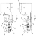
- FIG. 1 shows a wastewater lifting plant 10 with a screening device 12, the structure of which is shown in FIG Figure 3 and Figure 4 is shown.
- the arrows 18 show the direction of flow of wastewater 20 which is fed to the wastewater lifting plant via an inlet pipe 19.
- the waste water 20 is filled with the aid of a pump 16 through the sieve device 12 via a suction line 32 into a collecting container 22, whereby the level 34 of the waste water 20 in the collecting container 22 rises.
- This filling process of the collecting container 22 is illustrated by the arrows 18.
- the wastewater flows through the sieve device 12, and this sieve device 12 has the effect that solids are retained and collect in the area in front of the sieve device 12 in a bulk material collecting space 14.
- FIG. 2 shows a wastewater lifting plant 10, in which the level of the wastewater 20 in the collecting tank 22 has risen so far that the collecting tank 22 is emptied. This is done with the aid of the pump 16, which generates a delivery stream 26, the waste water 20 flowing from the collecting container 22 through the suction line 32, the sieve device 12, as well as through the bulk material collecting chamber 14 and a pressure pipe 28.
- the previously open shut-off valve 24 is closed by the conveying flow 28, so that no waste water can flow in via the inlet pipe 19 while the collecting container 22 is being emptied.
- a gate valve 30 is arranged in a manner known per se, with which the entire cross section of the pipe leading to the screening device 12 can be closed. This makes it possible to carry out repair or maintenance work on the sieve device 12 or other components.
- a module 36 of an exemplary embodiment of a screening device 12 according to the invention is shown in a perspective view.
- the module 36 includes a circular outer frame 38 with a plurality of openings 46. These openings 46 receive long pins 40 and short pins 42, the pin heads 44 of which bear against the outer wall of the outer frame 38.
- the pins 40, 42 are selected such that long pins 40 and short pins 42 alternate over the circumference of the outer frame 38.
- pins 40 and 42 do not extend perpendicular to the center of the outer frame 38, but run at an incline, deviating from the vertical direction of the conveying flow when the collecting container 22 is emptied in the direction of the conveying flow.
- the pins 40 and 42 are round and made of an elastic material, e.g. B. made of PUR (Shore 90 ° A).
- the resilient inclined pins are an important feature of the invention as opposed to the rigid and solid grids used in the prior art.
- the sieve device 12 according to the invention also has a comparable effect to a grid, which is formed by the alternately long and short pins 40 and 42, but the inclined and elastic pins allow certain vibrations, so that solids may be removed from the pins 40 and 42 when the collecting container is being filled have stuck, are removed by the powerful flow 26 from the pins 40 and 42, this effect is also supported by the fact that the pins do not have any edges but are round.
- the screening device comprises three modules 36 which are separated from one another by spacer frames 48. As can be seen, the three modules 36 are arranged slightly offset from one another when viewed in the circumferential direction of the outer frame 38 or the spacer frame 48, so that the pins 40, 42 of adjacent modules 36 are not in a line when viewed in the direction of the conveying flow 26. The more modules 36 arranged offset to one another are provided, the finer the screen formed by the modules 36 becomes.
- the spacer frames 48 are provided with bores 54, and the outer frames 38 also have corresponding bores 58. Positioning pins 56 are inserted through the adjacent bores 54 of the spacer frame and the bores 58 of the modules 36, whereby the modules 36 are positioned offset from one another in the desired manner .
- the modules 36 and the spacer frames 48 are located within a housing 50 and are secured by the in Figure 1
- the outer flanges 52 shown in FIG. 2 and FIG. 2 are held together, as a result of which the screening device 12 forms an independent component which is detachably connected to the sewage lifting plant 10.
- two spacer frames 48 are arranged next to one another on the outer right-hand side.
- the second far right spacer frame 48 ensures that the in Figure 4 Pins 40, 42 inclined to the right do not protrude from the housing 50 in the assembled state.
Landscapes
- Health & Medical Sciences (AREA)
- Life Sciences & Earth Sciences (AREA)
- Engineering & Computer Science (AREA)
- Hydrology & Water Resources (AREA)
- Public Health (AREA)
- Water Supply & Treatment (AREA)
- Sewage (AREA)
- Electrical Discharge Machining, Electrochemical Machining, And Combined Machining (AREA)
Priority Applications (2)
| Application Number | Priority Date | Filing Date | Title |
|---|---|---|---|
| PL15175639T PL2966231T3 (pl) | 2014-07-10 | 2015-07-07 | Układ rozdrabniająco-przepompowujący do ścieków z urządzeniem sitowym |
| HRP20201650TT HRP20201650T1 (hr) | 2014-07-10 | 2020-10-14 | Kanalizacijska crpna stanica s uređajem za filtriranje |
Applications Claiming Priority (1)
| Application Number | Priority Date | Filing Date | Title |
|---|---|---|---|
| DE102014109658.4A DE102014109658A1 (de) | 2014-07-10 | 2014-07-10 | Siebvorrichtung für eine Abwasserhebeanlage |
Publications (2)
| Publication Number | Publication Date |
|---|---|
| EP2966231A1 EP2966231A1 (de) | 2016-01-13 |
| EP2966231B1 true EP2966231B1 (de) | 2020-08-26 |
Family
ID=54014476
Family Applications (1)
| Application Number | Title | Priority Date | Filing Date |
|---|---|---|---|
| EP15175639.2A Active EP2966231B1 (de) | 2014-07-10 | 2015-07-07 | Abwasserhebeanlage mit siebvorrichtung |
Country Status (4)
| Country | Link |
|---|---|
| EP (1) | EP2966231B1 (pl) |
| DE (1) | DE102014109658A1 (pl) |
| HR (1) | HRP20201650T1 (pl) |
| PL (1) | PL2966231T3 (pl) |
Families Citing this family (3)
| Publication number | Priority date | Publication date | Assignee | Title |
|---|---|---|---|---|
| DE102018207243A1 (de) | 2018-05-09 | 2019-11-14 | KSB SE & Co. KGaA | Abwasserhebeanlage |
| DE102018207257A1 (de) * | 2018-05-09 | 2019-11-14 | KSB SE & Co. KGaA | Verfahren zum Betrieb einer Abwasserhebeanlage |
| CN112177146B (zh) * | 2020-10-13 | 2021-12-14 | 山西交控生态环境股份有限公司 | 一种污水提升系统 |
Citations (1)
| Publication number | Priority date | Publication date | Assignee | Title |
|---|---|---|---|---|
| WO2015055749A1 (de) * | 2013-10-17 | 2015-04-23 | Ksb Aktiengesellschaft | Verfahren zum erstellen einer abwasserhebeanlage in einem abwasserschacht sowie zugehörige abwasserhebeanlage |
Family Cites Families (7)
| Publication number | Priority date | Publication date | Assignee | Title |
|---|---|---|---|---|
| US2278178A (en) * | 1939-12-23 | 1942-03-31 | Chicago Pump Co | Strainer |
| US2760512A (en) * | 1951-08-01 | 1956-08-28 | Chicago Pump Co | By-pass valve |
| GB881917A (en) * | 1959-06-25 | 1961-11-08 | Fmc Corp | Liquid flow systems incorporating strainers |
| US3278035A (en) * | 1963-09-18 | 1966-10-11 | Pacific Pumping Company | Strainer device for sewage system |
| US3392842A (en) * | 1966-07-28 | 1968-07-16 | Amcodyne And Company | Self-cleaning counter-flow strainer assembly |
| DE19519305C2 (de) | 1995-05-26 | 2000-12-28 | Strate Technologie Fuer Abwass | Abwasserhebeanlage |
| PL2581508T3 (pl) | 2011-10-12 | 2014-09-30 | Strate Tech Fuer Abwasser Gmbh | Przepompownia ścieków |
-
2014
- 2014-07-10 DE DE102014109658.4A patent/DE102014109658A1/de not_active Withdrawn
-
2015
- 2015-07-07 PL PL15175639T patent/PL2966231T3/pl unknown
- 2015-07-07 EP EP15175639.2A patent/EP2966231B1/de active Active
-
2020
- 2020-10-14 HR HRP20201650TT patent/HRP20201650T1/hr unknown
Patent Citations (1)
| Publication number | Priority date | Publication date | Assignee | Title |
|---|---|---|---|---|
| WO2015055749A1 (de) * | 2013-10-17 | 2015-04-23 | Ksb Aktiengesellschaft | Verfahren zum erstellen einer abwasserhebeanlage in einem abwasserschacht sowie zugehörige abwasserhebeanlage |
Also Published As
| Publication number | Publication date |
|---|---|
| DE102014109658A1 (de) | 2016-01-14 |
| EP2966231A1 (de) | 2016-01-13 |
| HRP20201650T1 (hr) | 2020-12-25 |
| PL2966231T3 (pl) | 2021-01-25 |
Similar Documents
| Publication | Publication Date | Title |
|---|---|---|
| EP2581508B1 (de) | Abwasserhebeanlage | |
| DE69611310T2 (de) | Flüssigkeitsfilter | |
| EP2966231B1 (de) | Abwasserhebeanlage mit siebvorrichtung | |
| EP2508686B1 (de) | Rückhalteanlage für Niederschlagwasser und Abwasser | |
| EP3019673A1 (de) | Abwasserhebeanlage | |
| DE3403718C2 (pl) | ||
| DE102020112527A1 (de) | Vorrichtung zum Filtern einer Flüssigkeit und Verfahren zum Abreinigen eines Filterelemtens einer Vorrichtung zum Filtern einer Flüssigkeit | |
| DE2058395A1 (de) | Siebvorrichtung zum Abscheiden von Feststoffen aus Fluessigkeitsstroemen in Rohrleitungen | |
| DE19519497C2 (de) | Vorrichtung zum Sammeln und Reinigen von Regenwasser im Zulauf zum Regenwasserspeicher | |
| DE2658363A1 (de) | Vorrichtung zum filtern von fluessigen medien, insbesondere des nutzwassers in wasserversorgungen | |
| AT525755B1 (de) | Rechenanlage | |
| EP3069773A2 (de) | Filtervorrichtung für eine förderanlage zur förderung von sperr- und/oder feststoffhaltigen flüssigkeiten | |
| DE102005042457B4 (de) | Wasserreinigungsgerät für Teiche oder dergleichen Gewässer | |
| DE10002397A1 (de) | Absetzfilter | |
| DE202020105728U1 (de) | Vorrichtung zur Reinigung von Filtertüchern | |
| EP2405063B1 (de) | Abwasserbehandlungsanordnung | |
| DE102014211236A1 (de) | Abwasserbehandlungsanordnung | |
| DE102010030979A1 (de) | Rückhaltevorrichtung für eine Abwasserbehandlungsanordnung, Konstruktionseinheit gebildet aus Rückhaltevorrichtung und Abwasserbehandlungsanordnung | |
| DE102012203408A1 (de) | Abwasserbehandlungsanordnung, Strömungstrennwand, insbesondere zurVerwendung in einer derartigen Abwasserbehandlungsanordnung, und wenigstens eine derartige Strömungstrennwand umfassender Nachrüstbausatz | |
| DE202024101354U1 (de) | Straßenablauf mit Filter, und Filter für einen Straßenablauf | |
| EP1760046A1 (de) | Wasserreinigungsgerät für Teiche oder dergleichen Gewässer | |
| DE102013206658A1 (de) | Vorrichtung und Verfahren zum Rückspülen | |
| AT507726B1 (de) | Hydroventil | |
| DE102004013999C5 (de) | Vorrichtung zur Wiederaufbereitung von Schmutzwasser | |
| DE102008063413A1 (de) | Längssandfang in Kläranlagen, Wasserreinigungsanlagen und dergleichen |
Legal Events
| Date | Code | Title | Description |
|---|---|---|---|
| PUAI | Public reference made under article 153(3) epc to a published international application that has entered the european phase |
Free format text: ORIGINAL CODE: 0009012 |
|
| AK | Designated contracting states |
Kind code of ref document: A1 Designated state(s): AL AT BE BG CH CY CZ DE DK EE ES FI FR GB GR HR HU IE IS IT LI LT LU LV MC MK MT NL NO PL PT RO RS SE SI SK SM TR |
|
| AX | Request for extension of the european patent |
Extension state: BA ME |
|
| 17P | Request for examination filed |
Effective date: 20160712 |
|
| RBV | Designated contracting states (corrected) |
Designated state(s): AL AT BE BG CH CY CZ DE DK EE ES FI FR GB GR HR HU IE IS IT LI LT LU LV MC MK MT NL NO PL PT RO RS SE SI SK SM TR |
|
| STAA | Information on the status of an ep patent application or granted ep patent |
Free format text: STATUS: EXAMINATION IS IN PROGRESS |
|
| 17Q | First examination report despatched |
Effective date: 20180320 |
|
| GRAP | Despatch of communication of intention to grant a patent |
Free format text: ORIGINAL CODE: EPIDOSNIGR1 |
|
| STAA | Information on the status of an ep patent application or granted ep patent |
Free format text: STATUS: GRANT OF PATENT IS INTENDED |
|
| INTG | Intention to grant announced |
Effective date: 20200506 |
|
| GRAS | Grant fee paid |
Free format text: ORIGINAL CODE: EPIDOSNIGR3 |
|
| GRAA | (expected) grant |
Free format text: ORIGINAL CODE: 0009210 |
|
| STAA | Information on the status of an ep patent application or granted ep patent |
Free format text: STATUS: THE PATENT HAS BEEN GRANTED |
|
| AK | Designated contracting states |
Kind code of ref document: B1 Designated state(s): AL AT BE BG CH CY CZ DE DK EE ES FI FR GB GR HR HU IE IS IT LI LT LU LV MC MK MT NL NO PL PT RO RS SE SI SK SM TR |
|
| RAP1 | Party data changed (applicant data changed or rights of an application transferred) |
Owner name: STRATE TECHNOLOGIE FUER ABWASSER GMBH |
|
| REG | Reference to a national code |
Ref country code: GB Ref legal event code: FG4D Free format text: NOT ENGLISH |
|
| REG | Reference to a national code |
Ref country code: CH Ref legal event code: EP |
|
| REG | Reference to a national code |
Ref country code: AT Ref legal event code: REF Ref document number: 1306493 Country of ref document: AT Kind code of ref document: T Effective date: 20200915 |
|
| REG | Reference to a national code |
Ref country code: IE Ref legal event code: FG4D Free format text: LANGUAGE OF EP DOCUMENT: GERMAN |
|
| REG | Reference to a national code |
Ref country code: DE Ref legal event code: R096 Ref document number: 502015013313 Country of ref document: DE |
|
| REG | Reference to a national code |
Ref country code: HR Ref legal event code: TUEP Ref document number: P20201650 Country of ref document: HR |
|
| REG | Reference to a national code |
Ref country code: NL Ref legal event code: FP |
|
| REG | Reference to a national code |
Ref country code: SE Ref legal event code: TRGR |
|
| REG | Reference to a national code |
Ref country code: SK Ref legal event code: T3 Ref document number: E 35436 Country of ref document: SK |
|
| REG | Reference to a national code |
Ref country code: HR Ref legal event code: T1PR Ref document number: P20201650 Country of ref document: HR |
|
| REG | Reference to a national code |
Ref country code: LT Ref legal event code: MG4D |
|
| REG | Reference to a national code |
Ref country code: NO Ref legal event code: T2 Effective date: 20200826 |
|
| PG25 | Lapsed in a contracting state [announced via postgrant information from national office to epo] |
Ref country code: GR Free format text: LAPSE BECAUSE OF FAILURE TO SUBMIT A TRANSLATION OF THE DESCRIPTION OR TO PAY THE FEE WITHIN THE PRESCRIBED TIME-LIMIT Effective date: 20201127 Ref country code: PT Free format text: LAPSE BECAUSE OF FAILURE TO SUBMIT A TRANSLATION OF THE DESCRIPTION OR TO PAY THE FEE WITHIN THE PRESCRIBED TIME-LIMIT Effective date: 20201228 Ref country code: BG Free format text: LAPSE BECAUSE OF FAILURE TO SUBMIT A TRANSLATION OF THE DESCRIPTION OR TO PAY THE FEE WITHIN THE PRESCRIBED TIME-LIMIT Effective date: 20201126 Ref country code: LT Free format text: LAPSE BECAUSE OF FAILURE TO SUBMIT A TRANSLATION OF THE DESCRIPTION OR TO PAY THE FEE WITHIN THE PRESCRIBED TIME-LIMIT Effective date: 20200826 Ref country code: FI Free format text: LAPSE BECAUSE OF FAILURE TO SUBMIT A TRANSLATION OF THE DESCRIPTION OR TO PAY THE FEE WITHIN THE PRESCRIBED TIME-LIMIT Effective date: 20200826 |
|
| PG25 | Lapsed in a contracting state [announced via postgrant information from national office to epo] |
Ref country code: IS Free format text: LAPSE BECAUSE OF FAILURE TO SUBMIT A TRANSLATION OF THE DESCRIPTION OR TO PAY THE FEE WITHIN THE PRESCRIBED TIME-LIMIT Effective date: 20201226 Ref country code: RS Free format text: LAPSE BECAUSE OF FAILURE TO SUBMIT A TRANSLATION OF THE DESCRIPTION OR TO PAY THE FEE WITHIN THE PRESCRIBED TIME-LIMIT Effective date: 20200826 Ref country code: LV Free format text: LAPSE BECAUSE OF FAILURE TO SUBMIT A TRANSLATION OF THE DESCRIPTION OR TO PAY THE FEE WITHIN THE PRESCRIBED TIME-LIMIT Effective date: 20200826 |
|
| PG25 | Lapsed in a contracting state [announced via postgrant information from national office to epo] |
Ref country code: EE Free format text: LAPSE BECAUSE OF FAILURE TO SUBMIT A TRANSLATION OF THE DESCRIPTION OR TO PAY THE FEE WITHIN THE PRESCRIBED TIME-LIMIT Effective date: 20200826 Ref country code: SM Free format text: LAPSE BECAUSE OF FAILURE TO SUBMIT A TRANSLATION OF THE DESCRIPTION OR TO PAY THE FEE WITHIN THE PRESCRIBED TIME-LIMIT Effective date: 20200826 Ref country code: RO Free format text: LAPSE BECAUSE OF FAILURE TO SUBMIT A TRANSLATION OF THE DESCRIPTION OR TO PAY THE FEE WITHIN THE PRESCRIBED TIME-LIMIT Effective date: 20200826 Ref country code: DK Free format text: LAPSE BECAUSE OF FAILURE TO SUBMIT A TRANSLATION OF THE DESCRIPTION OR TO PAY THE FEE WITHIN THE PRESCRIBED TIME-LIMIT Effective date: 20200826 |
|
| REG | Reference to a national code |
Ref country code: DE Ref legal event code: R097 Ref document number: 502015013313 Country of ref document: DE |
|
| PG25 | Lapsed in a contracting state [announced via postgrant information from national office to epo] |
Ref country code: AL Free format text: LAPSE BECAUSE OF FAILURE TO SUBMIT A TRANSLATION OF THE DESCRIPTION OR TO PAY THE FEE WITHIN THE PRESCRIBED TIME-LIMIT Effective date: 20200826 Ref country code: ES Free format text: LAPSE BECAUSE OF FAILURE TO SUBMIT A TRANSLATION OF THE DESCRIPTION OR TO PAY THE FEE WITHIN THE PRESCRIBED TIME-LIMIT Effective date: 20200826 |
|
| PLBE | No opposition filed within time limit |
Free format text: ORIGINAL CODE: 0009261 |
|
| STAA | Information on the status of an ep patent application or granted ep patent |
Free format text: STATUS: NO OPPOSITION FILED WITHIN TIME LIMIT |
|
| 26N | No opposition filed |
Effective date: 20210527 |
|
| REG | Reference to a national code |
Ref country code: HR Ref legal event code: ODRP Ref document number: P20201650 Country of ref document: HR Payment date: 20210630 Year of fee payment: 7 |
|
| PG25 | Lapsed in a contracting state [announced via postgrant information from national office to epo] |
Ref country code: SI Free format text: LAPSE BECAUSE OF FAILURE TO SUBMIT A TRANSLATION OF THE DESCRIPTION OR TO PAY THE FEE WITHIN THE PRESCRIBED TIME-LIMIT Effective date: 20200826 |
|
| REG | Reference to a national code |
Ref country code: CH Ref legal event code: PL |
|
| PG25 | Lapsed in a contracting state [announced via postgrant information from national office to epo] |
Ref country code: MC Free format text: LAPSE BECAUSE OF FAILURE TO SUBMIT A TRANSLATION OF THE DESCRIPTION OR TO PAY THE FEE WITHIN THE PRESCRIBED TIME-LIMIT Effective date: 20200826 |
|
| REG | Reference to a national code |
Ref country code: BE Ref legal event code: MM Effective date: 20210731 |
|
| PG25 | Lapsed in a contracting state [announced via postgrant information from national office to epo] |
Ref country code: LI Free format text: LAPSE BECAUSE OF NON-PAYMENT OF DUE FEES Effective date: 20210731 Ref country code: CH Free format text: LAPSE BECAUSE OF NON-PAYMENT OF DUE FEES Effective date: 20210731 |
|
| PG25 | Lapsed in a contracting state [announced via postgrant information from national office to epo] |
Ref country code: LU Free format text: LAPSE BECAUSE OF NON-PAYMENT OF DUE FEES Effective date: 20210707 |
|
| PG25 | Lapsed in a contracting state [announced via postgrant information from national office to epo] |
Ref country code: IE Free format text: LAPSE BECAUSE OF NON-PAYMENT OF DUE FEES Effective date: 20210707 Ref country code: BE Free format text: LAPSE BECAUSE OF NON-PAYMENT OF DUE FEES Effective date: 20210731 |
|
| REG | Reference to a national code |
Ref country code: HR Ref legal event code: ODRP Ref document number: P20201650 Country of ref document: HR Payment date: 20220628 Year of fee payment: 8 |
|
| REG | Reference to a national code |
Ref country code: AT Ref legal event code: MM01 Ref document number: 1306493 Country of ref document: AT Kind code of ref document: T Effective date: 20210707 |
|
| PG25 | Lapsed in a contracting state [announced via postgrant information from national office to epo] |
Ref country code: AT Free format text: LAPSE BECAUSE OF NON-PAYMENT OF DUE FEES Effective date: 20210707 |
|
| REG | Reference to a national code |
Ref country code: DE Ref legal event code: R082 Ref document number: 502015013313 Country of ref document: DE Representative=s name: ULLRICH & NAUMANN PATENT- UND RECHTSANWAELTE, , DE |
|
| PG25 | Lapsed in a contracting state [announced via postgrant information from national office to epo] |
Ref country code: HU Free format text: LAPSE BECAUSE OF FAILURE TO SUBMIT A TRANSLATION OF THE DESCRIPTION OR TO PAY THE FEE WITHIN THE PRESCRIBED TIME-LIMIT; INVALID AB INITIO Effective date: 20150707 |
|
| PG25 | Lapsed in a contracting state [announced via postgrant information from national office to epo] |
Ref country code: CY Free format text: LAPSE BECAUSE OF FAILURE TO SUBMIT A TRANSLATION OF THE DESCRIPTION OR TO PAY THE FEE WITHIN THE PRESCRIBED TIME-LIMIT Effective date: 20200826 |
|
| REG | Reference to a national code |
Ref country code: HR Ref legal event code: ODRP Ref document number: P20201650 Country of ref document: HR Payment date: 20230628 Year of fee payment: 9 |
|
| PG25 | Lapsed in a contracting state [announced via postgrant information from national office to epo] |
Ref country code: MK Free format text: LAPSE BECAUSE OF FAILURE TO SUBMIT A TRANSLATION OF THE DESCRIPTION OR TO PAY THE FEE WITHIN THE PRESCRIBED TIME-LIMIT Effective date: 20200826 |
|
| REG | Reference to a national code |
Ref country code: HR Ref legal event code: ODRP Ref document number: P20201650 Country of ref document: HR Payment date: 20240701 Year of fee payment: 10 |
|
| PG25 | Lapsed in a contracting state [announced via postgrant information from national office to epo] |
Ref country code: MT Free format text: LAPSE BECAUSE OF FAILURE TO SUBMIT A TRANSLATION OF THE DESCRIPTION OR TO PAY THE FEE WITHIN THE PRESCRIBED TIME-LIMIT Effective date: 20200826 |
|
| PGFP | Annual fee paid to national office [announced via postgrant information from national office to epo] |
Ref country code: PL Payment date: 20250624 Year of fee payment: 11 |
|
| PGFP | Annual fee paid to national office [announced via postgrant information from national office to epo] |
Ref country code: SK Payment date: 20250630 Year of fee payment: 11 |
|
| PGFP | Annual fee paid to national office [announced via postgrant information from national office to epo] |
Ref country code: CZ Payment date: 20250625 Year of fee payment: 11 |
|
| REG | Reference to a national code |
Ref country code: HR Ref legal event code: ODRP Ref document number: P20201650 Country of ref document: HR Payment date: 20250701 Year of fee payment: 11 |
|
| PGFP | Annual fee paid to national office [announced via postgrant information from national office to epo] |
Ref country code: NL Payment date: 20250723 Year of fee payment: 11 |
|
| PGFP | Annual fee paid to national office [announced via postgrant information from national office to epo] |
Ref country code: DE Payment date: 20250929 Year of fee payment: 11 |
|
| PGFP | Annual fee paid to national office [announced via postgrant information from national office to epo] |
Ref country code: NO Payment date: 20250722 Year of fee payment: 11 |
|
| PGFP | Annual fee paid to national office [announced via postgrant information from national office to epo] |
Ref country code: IT Payment date: 20250731 Year of fee payment: 11 |
|
| PGFP | Annual fee paid to national office [announced via postgrant information from national office to epo] |
Ref country code: GB Payment date: 20250724 Year of fee payment: 11 |
|
| PGFP | Annual fee paid to national office [announced via postgrant information from national office to epo] |
Ref country code: HR Payment date: 20250701 Year of fee payment: 11 |
|
| PGFP | Annual fee paid to national office [announced via postgrant information from national office to epo] |
Ref country code: FR Payment date: 20250723 Year of fee payment: 11 |
|
| PGFP | Annual fee paid to national office [announced via postgrant information from national office to epo] |
Ref country code: SE Payment date: 20250723 Year of fee payment: 11 |
|
| PG25 | Lapsed in a contracting state [announced via postgrant information from national office to epo] |
Ref country code: TR Free format text: LAPSE BECAUSE OF FAILURE TO SUBMIT A TRANSLATION OF THE DESCRIPTION OR TO PAY THE FEE WITHIN THE PRESCRIBED TIME-LIMIT Effective date: 20200826 |