EP2966237A1 - Einrollbare Sackmarkise - Google Patents
Einrollbare Sackmarkise Download PDFInfo
- Publication number
- EP2966237A1 EP2966237A1 EP14002363.1A EP14002363A EP2966237A1 EP 2966237 A1 EP2966237 A1 EP 2966237A1 EP 14002363 A EP14002363 A EP 14002363A EP 2966237 A1 EP2966237 A1 EP 2966237A1
- Authority
- EP
- European Patent Office
- Prior art keywords
- awning
- shaft
- roll
- sack
- gear
- Prior art date
- Legal status (The legal status is an assumption and is not a legal conclusion. Google has not performed a legal analysis and makes no representation as to the accuracy of the status listed.)
- Granted
Links
Images


Classifications
-
- E—FIXED CONSTRUCTIONS
- E04—BUILDING
- E04F—FINISHING WORK ON BUILDINGS, e.g. STAIRS, FLOORS
- E04F10/00—Sunshades, e.g. Florentine blinds or jalousies; Outside screens; Awnings or baldachins
- E04F10/02—Sunshades, e.g. Florentine blinds or jalousies; Outside screens; Awnings or baldachins of flexible canopy materials, e.g. canvas ; Baldachins
- E04F10/06—Sunshades, e.g. Florentine blinds or jalousies; Outside screens; Awnings or baldachins of flexible canopy materials, e.g. canvas ; Baldachins comprising a roller-blind with means for holding the end away from a building
- E04F10/0644—Sunshades, e.g. Florentine blinds or jalousies; Outside screens; Awnings or baldachins of flexible canopy materials, e.g. canvas ; Baldachins comprising a roller-blind with means for holding the end away from a building with mechanisms for unrolling or balancing the blind
- E04F10/0648—Sunshades, e.g. Florentine blinds or jalousies; Outside screens; Awnings or baldachins of flexible canopy materials, e.g. canvas ; Baldachins comprising a roller-blind with means for holding the end away from a building with mechanisms for unrolling or balancing the blind acting on the roller tube
-
- E—FIXED CONSTRUCTIONS
- E04—BUILDING
- E04F—FINISHING WORK ON BUILDINGS, e.g. STAIRS, FLOORS
- E04F10/00—Sunshades, e.g. Florentine blinds or jalousies; Outside screens; Awnings or baldachins
- E04F10/02—Sunshades, e.g. Florentine blinds or jalousies; Outside screens; Awnings or baldachins of flexible canopy materials, e.g. canvas ; Baldachins
- E04F10/06—Sunshades, e.g. Florentine blinds or jalousies; Outside screens; Awnings or baldachins of flexible canopy materials, e.g. canvas ; Baldachins comprising a roller-blind with means for holding the end away from a building
- E04F10/0644—Sunshades, e.g. Florentine blinds or jalousies; Outside screens; Awnings or baldachins of flexible canopy materials, e.g. canvas ; Baldachins comprising a roller-blind with means for holding the end away from a building with mechanisms for unrolling or balancing the blind
- E04F10/0655—Sunshades, e.g. Florentine blinds or jalousies; Outside screens; Awnings or baldachins of flexible canopy materials, e.g. canvas ; Baldachins comprising a roller-blind with means for holding the end away from a building with mechanisms for unrolling or balancing the blind acting on the movable end, e.g. front bar
-
- E—FIXED CONSTRUCTIONS
- E04—BUILDING
- E04F—FINISHING WORK ON BUILDINGS, e.g. STAIRS, FLOORS
- E04F10/00—Sunshades, e.g. Florentine blinds or jalousies; Outside screens; Awnings or baldachins
- E04F10/02—Sunshades, e.g. Florentine blinds or jalousies; Outside screens; Awnings or baldachins of flexible canopy materials, e.g. canvas ; Baldachins
- E04F10/06—Sunshades, e.g. Florentine blinds or jalousies; Outside screens; Awnings or baldachins of flexible canopy materials, e.g. canvas ; Baldachins comprising a roller-blind with means for holding the end away from a building
- E04F10/0666—Accessories
- E04F10/0681—Support posts for the movable end of the blind
-
- E—FIXED CONSTRUCTIONS
- E04—BUILDING
- E04H—BUILDINGS OR LIKE STRUCTURES FOR PARTICULAR PURPOSES; SWIMMING OR SPLASH BATHS OR POOLS; MASTS; FENCING; TENTS OR CANOPIES, IN GENERAL
- E04H15/00—Tents or canopies, in general
- E04H15/02—Tents combined or specially associated with other devices
- E04H15/06—Tents at least partially supported by vehicles
- E04H15/08—Trailer awnings or the like
Definitions
- the invention relates to a rollable sack awning with end arranged awning shaft.
- a rollable sack awning is well known in the art.
- Such a sack awning is attached to the caravan or motorhome on the side wall in the transition to the roof area.
- the side wall of the caravan or motorhome on a so-called piping rail, wherein corresponding to the bag awning has a piping, wherein the piping of the piping rail is receivable.
- Keder and piping rail form a fastening device.
- the sack awning extends over the substantially horizontal roof area of the caravan or motorhome.
- the Awning itself has an awning shaft at the front end, being attached to the awning shaft for erecting the awning on both sides supports, which are guyed over ropes.
- a sack awning which has a front wall and a side wall for forming awning tent.
- retracted awnings for caravans or motorhomes are known.
- a retracted awning is characterized by the fact that it follows the contour of the side wall of the caravan both in the area of the roof and in the area of the front and rear end face.
- the sack awning is the roof for such a retracted awning.
- From the EP 2 492 413 B is such a retracted awning known in which the bag awning can be stowed in the bag located on the vehicle in a simple manner after loosening the side and front parts of the awning.
- a sack awning is not always mounted in handle height on the side wall of the vehicle.
- the height at which the awning is arranged is well over 2 meters. It is therefore Required that when rolling up, the persons involved in the rolling up on chairs or ladders to roll up the fabric on the awning of the blind awning so far that it can be stowed in its entirety as a roll in the corresponding bag.
- the awning shaft has a not inconsiderable weight. This means that especially older people are difficult to roll the bag awning; this irrespective of the fact that due to the need for z. As chairs to rise to curl up the bag awning, also a not insignificant risk of accidents exists.
- the object underlying the invention is to remedy this situation;
- the task is to facilitate the curling of the bag awning.
- the invention proposes that the awning shaft has a device for rolling up the awning on at least one end face.
- This means that the awning shaft for rolling the bag awning is set in rotation, and in particular on the one hand by an electric motor and the other by hand.
- the device is manually operated and comprises a gear for rolling up the awning.
- a crank linkage can be attached in order to set the awning shaft by manual operation in rotation.
- the transmission in this case has an adapter, wherein the adapter is connected rotatably relative to the transmission with this, and wherein the adapter is rotatably connected to the awning shaft but is set by the transmission upon actuation of the crank link in rotation.
- the transmission is in this case designed, in particular, as a deflection gear and furthermore as a worm deflection gear.
- the transmission has a Gearbox.
- the awning shaft is held on either side by a support and braced by the side.
- One of the supports may be connected to the transmission housing in order to absorb the resulting moment upon actuation of the crank linkage. Basically, however, that in other ways, the moment can be intercepted.
- the fabric of the bag awning is then rolled up onto the awning shaft. The rolling-up takes place until the awning shaft with the wrapped fabric web rests against the side wall of the vehicle and can be stowed in the bag attached to the vehicle.
- a second embodiment is characterized in that the device is driven by an electric motor. That is, there is provided an electric motor which is rotatably connected to the awning shaft. In order to ensure a corresponding under- or translation of the rotational speed of the electric motor, a transmission is provided which is located between the electric motor and the awning shaft. It can be provided that the transmission is designed as a planetary gear, with the electric motor to form a drive unit is in series with the planetary gear with at least one planetary gear stage. Such electric motors with a downstream planetary gear stage in series are z. B. from Dunker ® commercially available. It is provided that the drive unit has an outwardly guided shaft which serves to receive the moment when the output of the motor via the gear housing takes place on the awning shaft.
- the planetary gear has a gear housing, which is rotationally fixed in connection with the awning shaft.
- the motor shaft of the electric motor can be fixed by the fact that the support, with which the awning shaft is supported on the ground, is designed such that it can, for. B. positively holds the motor shaft and thus is able to absorb the moment during operation of the engine.
- the procedure for rolling up the awning in both embodiments such that the supports are brought in the extended state of the awning with its bottom end in the region of the side wall of the vehicle, in which case z. B. the electric motor, the awning shaft rotates slowly, with the fabric of the bag awning rolls up on the awning shaft.
- at least one support takes on the torque of the electric motor of the drive unit or the torque during manual operation also on the crank linkage.
- a combination of hand-operated and electric motor driven awning shaft has been found. That is, at one end side of the awning shaft is an electromotive and at the other end a hand-operated device for rolling up the awning shaft. This makes sense against the background that electricity is not always available.
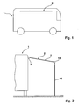
- Fig. 1 the vehicle is designated 1.
- bag awning On the side wall of the vehicle schematically indicated and designated 2 bag awning is provided.
- Fig. 2 shows a front view of the vehicle according to Fig. 2 with the bag awning extended.
- the bag 5 for the bag awning wherein the fabric 7 of the bag awning 2 is hinged to the vehicle within the bag 5.
- the designated 10 awning shaft At the front end of the fabric is the designated 10 awning shaft, which is supported by respective lateral supports 12 relative to the ground.
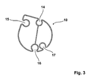
- Fig. 3 now shows an awning shaft in cross section.
- the awning shaft 10 in this case has various circular recesses 14, 15, 16 and 17, wherein the parallel to the longitudinal axis of the awning shaft 10 extending round recesses 14 - 17 form so-called Kederö réelleen that serve to accommodate, for example, the fabric 7 of the awning, wherein the fabric connected by means of a wrapped in the corresponding recess Keder with the awning shaft becomes.
- Kederötechnisch serve to accommodate, for example, the fabric 7 of the awning, wherein the fabric connected by means of a wrapped in the corresponding recess Keder with the awning shaft becomes.
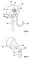
- Fig. 4 now results in the total designated 20 first means by which the awning shaft is rolled up by manual operation.
- the device 20 in this case comprises the gear 27 and the adapter 25.
- the adapter 25 is rotatable relative to the gear 27.
- the adapter 25 has the two drive pins 21 and 22, which are insertable into two of the corresponding recesses 14 to 17 in the awning shaft 10. This means that upon rotation of the adapter 25 by the drive pins 21 and 22, the awning shaft 10 is set in rotation.
- the transmission 27 is provided.
- the transmission 27 is, as this particular in view of the representation of Fig. 4 but also the Fig. 5 results, designed as Schneckenumlenkgetriebe.
- the worm gear has a pinion 30, which is driven by a arranged on a shaft screw 28a as part of the hook 28.
- a rotary crank linkage (not shown) can be recognized.
- the pinion 30 is rotated by the worm 28a and thus finally the shaft 31, whereby the adapter 25, which is in a rotationally fixed connection with the shaft 31, is set in rotation.
- the support 12 is fixedly connected to the housing 29 of the transmission 27. For this purpose has, how this in view of Fig. 6 but also from Fig.
- the Fig. 7 and 8th schematically show a arranged at least on one end side means for rolling up the awning, which is operated by an electric motor.
- the electromotive device has the reference numeral 40.
- the electromotive device 40 comprises a housing 42 which accommodates both the electric motor 34, and a planetary gear 36 with at least one Planentengetriebeeck (shown schematically).
- the tarpaulin gear 36 is in communication with the housing 42, so that upon actuation of the electric motor 34, the housing 42 rotates.
- the housing 42 has the two drive pins 21 and 22, which form a rotationally fixed connection between the housing 42 of the transmission and the awning shaft 10 with the awning shaft 10.
- Corresponding engines with flanged gearbox are commercially available, for. B. at the company Dunker ®, available.
- the electric motor 34 has a motor shaft 38, which is held rotationally fixed by the support 12, so that the torque which is produced when the awning shaft 10 is driven by the electric motor 34 can thereby be intercepted ( Fig. 8 ).
Landscapes
- Engineering & Computer Science (AREA)
- Architecture (AREA)
- Civil Engineering (AREA)
- Structural Engineering (AREA)
- Building Awnings And Sunshades (AREA)
Abstract
Description
- Die Erfindung betrifft eine einrollbare Sackmarkise mit endseitig angeordneter Markisenwelle.
- Eine einrollbare Sackmarkise ist aus dem Stand der Technik hinreichend bekannt. Eine solche Sackmarkise wird am Wohnwagen oder Wohnmobil an der Seitenwand im Übergang zum Dachbereich befestigt. Hierzu weist die Seitenwand des Wohnwagens oder Wohnmobils eine sogenannte Kederschiene auf, wobei korrespondierend hierzu die Sackmarkise einen Keder besitzt, wobei der Keder von der Kederschiene aufnehmbar ist. Keder und Kederschiene bilden eine Befestigungseinrichtung. Die Sackmarkise erstreckt sich über den im Wesentlichen horizontal verlaufenden Dachbereich des Wohnwagens oder Wohnmobils. Die Markise selbst weist am vorderen Ende eine Markisenwelle auf, wobei an der Markisenwelle zum Aufstellen der Markise zu beiden Seiten Stützen angebracht werden, die über Seile abgespannt werden. Darüber hinaus ist bekannt, an der Markise Seitenwände anzubringen, sodass ein Markisenzelt entsteht.
- Aus der
EP 2 341 197 A2 ist in diesem Zusammenhang eine Sackmarkise bekannt, die eine Front- und eine Seitenwand zur Bildung eines Markisenzelts aufweist. - Des Weiteren sind sogenannte eingezogene Vorzelte für Wohnwagen oder Wohnmobile bekannt. Ein solches eingezogenes Vorzelt zeichnet sich dadurch aus, dass es der Kontur der Seitenwand des Wohnwagens sowohl im Bereich des Daches als auch im Bereich der vorderen und hinteren Stirnfläche folgt. Das heißt, dass durch ein solches eingezogenes Vorzelt die komplette Seitenwand des Wohnwagens oder Wohnmobils erfasst ist. Auch hier bildet die Sackmarkise das Dach für ein solches eingezogenes Vorzelt. Aus der
EP 2 492 413 B ist ein solches eingezogenes Vorzelt bekannt, bei dem auf einfache Art und Weise nach Lösen der Seiten- und Frontteile des Vorzeltes die Sackmarkise im am Fahrzeug befindlichen Sack verstaut werden kann. - Zum Verstauen der Sackmarkise in dem entsprechenden Sack am Fahrzeug wird üblicherweise so vorgegangen, dass die am vorderen Ende angeordnete Markisenwelle von Hand aufgerollt wird, um im aufgerollten Zustand im besagten Sack an der Fahrzeugseitenwand untergebracht zu werden.
- Nun ist es so, dass eine Sackmarkise durchaus nicht immer in Griffhöhe an der Seitenwand des Fahrzeugs angebracht ist. Vielfach liegt die Höhe, in welcher die Markise angeordnet ist, bei weit über 2 Metern. Es ist daher erforderlich, dass beim Aufrollen die Personen, die mit dem Aufrollen beschäftigt sind, auf Stühle oder Leitern steigen, um die Stoffbahn auf der Markisenwelle der Sackmarkise so weit aufzurollen, dass diese in Gänze als Rolle in dem entsprechenden Sack verstaut werden kann. Hinzu kommt noch, dass die Markisenwelle ein nicht unerhebliches Gewicht aufweist. Das heißt, dass insbesondere älteren Leuten das Einrollen der Sackmarkise Schwierigkeiten bereitet; dies ganz unabhängig davon, dass aufgrund der Notwendigkeit auf z. B. Stühle zu steigen, um die Sackmarkise zusammenzurollen, auch eine nicht unerhebliche Unfallgefahr besteht.
- Die der Erfindung zugrunde liegende Aufgabe besteht darin, hier Abhilfe zu schaffen; insbesondere besteht die Aufgabe darin, das Einrollen der Sackmarkise zu erleichtern.
- Zur Lösung der Aufgabe wird erfindungsgemäß vorgeschlagen, dass die Markisenwelle an mindestens einer Stirnseite eine Einrichtung zum Aufrollen der Markise aufweist. Das heißt, dass die Markisenwelle zum Einrollen der Sackmarkise in Rotation versetzbar ist, und zwar insbesondere zum einen elektromotorisch und zum anderen von Hand.
- Nach einer ersten Ausführungsform ist in diesem Zusammenhang vorgesehen, dass die Einrichtung handbetrieben ist und zum Aufrollen der Markise ein Getriebe umfasst. An das Getriebe kann ein Kurbelgestänge angehängt werden, um die Markisenwelle per Handbetrieb in Rotation zu versetzen. Das Getriebe weist hierbei einen Adapter auf, wobei der Adapter relativ zu dem Getriebe verdrehbar mit diesem verbunden ist, und wobei der Adapter mit der Markisenwelle drehfest verbunden ist aber durch das Getriebe bei Betätigung des Kurbelgestänges in Rotation versetzbar ist. Das Getriebe ist hierbei insbesondere als Umlenkgetriebe und weiterhin als Schneckenumlenkgetriebe ausgebildet. Das Getriebe besitzt ein Getriebegehäuse. Die Markisenwelle ist zu beiden Seiten durch jeweils eine Stütze gehalten und durch die Seite abgespannt. Eine der Stützen kann mit dem Getriebegehäuse verbunden sein, um bei Betätigung des Kurbelgestänges das hierbei entstehende Moment aufzunehmen. Grundsätzlich gilt allerdings, dass auch auf andere Art und Weise das Moment abgefangen werden kann. Bei Betätigung des Kurbelgestänges wird dann die Stoffbahn der Sackmarkise auf die Markisenwelle aufgerollt. Der Aufrollvorgang erfolgt so lange, bis die Markisenwelle mit der umwickelten Stoffbahn an der Seitenwand des Fahrzeugs anliegt und in dem am Fahrzeug angebrachten Sack verstaut werden kann.
- Eine zweite Ausführungsform zeichnet sich dadurch aus, dass die Einrichtung elektromotorisch angetrieben ist. Das heißt, es ist ein Elektromotor vorgesehen, der mit der Markisenwelle in drehfester Verbindung steht. Um für eine entsprechende Unter- oder Übersetzung der Drehzahl des Elektromotors zu sorgen, ist ein Getriebe vorgesehen, das sich zwischen Elektromotor und Markisenwelle befindet. Hierbei kann vorgesehen sein, dass das Getriebe als Planetengetriebe ausgebildet ist, wobei sich in Reihe zu dem Planetengetriebe mit mindestens einer Planetengetriebestufe der Elektromotor zur Bildung einer Antriebseinheit befindet. Solche Elektromotoren mit einer in Reihe nachgeordneten Planetengetriebestufe sind z. B. von der Firma Dunker® käuflich erhältlich. Hierbei ist vorgesehen, dass die Antriebseinheit eine nach außen geführte Welle aufweist, die der Aufnahme des Moments dient, wenn der Abtrieb des Motors über das Getriebegehäuse auf die Markisenwelle erfolgt. Das heißt, dass das Planetengetriebe ein Getriebegehäuse aufweist, das mit der Markisenwelle verdrehfest in Verbindung steht. Die Motorwelle des Elektromotors kann hierbei dadurch fixiert werden, das die Stütze, mit der die Markisenwelle auf dem Untergrund abgestützt ist, derart ausgebildet ist, dass sie z. B. formschlüssig die Motorwelle hält und insofern in der Lage ist, das Moment bei Betrieb des Motors aufzunehmen.
- Im Einzelnen wird zum Aufrollen der Markise bei beiden Ausführungsformen derart vorgegangen, dass die Stützen im ausgefahrenen Zustand der Markise mit ihrem bodenseitigen Ende in den Bereich der Seitenwand des Fahrzeugs gebracht werden, wobei dann bei Betätigung z. B. des Elektromotors sich die Markisenwelle langsam dreht, wobei sich die Stoffbahn der Sackmarkise auf die Markisenwelle aufrollt. Wie bereits ausgeführt, nimmt hierbei zumindest die eine Stütze das Drehmoment des Elektromotors der Antriebseinheit oder das Drehmoment beim Handbetrieb auch das Kurbelgestänge auf.
- Als besonders vorteilhaft hat sich eine Kombination aus handbetriebener und elektromotorisch angetriebener Markisenwelle herausgestellt. Das heißt, an der einen Stirnseite der Markisenwelle befindet sich eine elektromotorische und an der anderen Stirnseite eine handbetriebene Einrichtung zum Aufrollen der Markisenwelle. Dies macht Sinn vor dem Hintergrund, dass nicht immer Strom zur Verfügung steht.
- Anhand der Zeichnungen wird die Erfindung nachstehend beispielhaft näher erläutert.
- Fig. 1
- zeigt hierbei schematisch ein Wohnmobil in einer Seitenansicht;
- Fig. 2
- zeigt eine Ansicht gemäß
Fig. 1 von der Vorderseite; - Fig. 3
- zeigt die Markisenwelle in einer Seitenansicht im Schnitt;
- Fig. 4
- zeigt die Markisenwelle mit angesetztem Getriebe für den Handbetrieb;
- Fig. 5
- zeigt eine Ansicht gemäß der Linie V-V aus
Fig. 4 , wobei das Getriebe der besseren Darstellung wegen im Ausbruch dargestellt ist; - Fig. 6
- zeigt eine perspektivische Ansicht auf die Befestigung des Getriebes an der Stütze;
- Fig. 7
- zeigt eine an der Stirnseite der Markisenwelle angeordnete elektromotorisch betriebene Einrichtung zum Aufrollen der Markisenwelle mit in Reihe angeordnetem Planentengetriebe;
- Fig. 8
- zeigt eine Ansicht gemäß der Linie VIII/VIII aus
Fig. 7 . - Gemäß
Fig. 1 ist das Fahrzeug mit 1 bezeichnet. An der Seitenwand des Fahrzeugs ist die schematisch dargestellte und mit 2 bezeichnete Sackmarkise vorgesehen.Fig. 2 zeigt eine Frontansicht auf das Fahrzeug gemäßFig. 2 , wobei die Sackmarkise ausgefahren ist. Hierbei befindet sich an der Seitenwand des Fahrzeuges der Sack 5 für die Sackmarkise, wobei innerhalb des Sackes 5 die Stoffbahn 7 der Sackmarkise 2 am Fahrzeug angelenkt ist. Am vorderen Ende der Stoffbahn befindet sich die mit 10 bezeichnete Markisenwelle, die durch jeweils seitliche Stützen 12 gegenüber dem Untergrund abgestützt ist. -
Fig. 3 zeigt nun eine Markisenwelle im Querschnitt. Die Markisenwelle 10 weist hierbei verschiedene kreisrunde Ausnehmungen 14, 15, 16 und 17 auf, wobei die sich parallel zur Längsachse der Markisenwelle 10 erstreckenden runden Ausnehmungen 14 - 17 sogenannte Kederöffnungen bilden, die der Aufnahme beispielsweise der Stoffbahn 7 der Markise dienen, wobei die Stoffbahn mittels eines in die entsprechende Ausnehmung eingeschlagenen Keders mit der Markisenwelle verbunden wird. Gleiches gilt für eine entsprechende Ausnehmung zur Anbringung einer Zeltbahn an der Stirnseite zur Bildung eines Zeltes. - Aus
Fig. 4 ergibt sich nun die insgesamt mit 20 bezeichnete erste Einrichtung, mittels derer durch Handbetrieb die Markisenwelle aufgerollt wird. Die Einrichtung 20 umfasst hierbei das Getriebe 27 und den Adapter 25. Der Adapter 25 ist relativ zu dem Getriebe 27 verdrehbar. Der Adapter 25 besitzt die beiden Antriebsstifte 21 und 22, die in zwei der entsprechenden Ausnehmungen 14 bis 17 in der Markisenwelle 10 einführbar sind. Das heißt, dass bei Verdrehen des Adapters 25 durch die Antriebsstifte 21 und 22 die Markisenwelle 10 in Rotation versetzt wird. Um den Adapter 25 nunmehr in Rotation zu versetzen, ist das Getriebe 27 vorgesehen. Das Getriebe 27 ist, wie sich dies insbesondere in Anschauung der Darstellung derFig. 4 aber auch derFig. 5 ergibt, als Schneckenumlenkgetriebe ausgebildet. Das Schneckenumlenkgetriebe besitzt ein Ritzel 30, das von einer auf einer Welle angeordneten Schnecke 28a als Bestandteil des Hakens 28 angetrieben wird. An den Haken 28 kann ein Drehkurbelgestänge (nicht dargestellt) angesetzt werden. Bei Verdrehung des Hakens 28 verdreht sich durch die Schnecke 28a das Ritzel 30 und damit schlussendlich die Welle 31, wodurch der Adapter 25, der mit der Welle 31 in verdrehfester Verbindung steht, in Rotation versetzt wird. Um das beim Verdrehen des Hakens 28 entstehende Drehmoment aufzunehmen, ist vorgesehen, dass die Stütze 12 fest mit dem Gehäuse 29 des Getriebes 27 verbunden ist. Hierzu besitzt, wie sich dies in Anschauung vonFig. 6 aber auch vonFig. 5 ergibt, die Stütze 12 an ihrem freien Ende einen Gewindezapfen 12a, an dem ein Kulissenstift 12b befestigt ist, der durch den Gewindezapfen 12a in der Aussparung 12c des Getriebegehäuses 29 des Getriebegehäuses 27 verspannbar ist. Die Verspannung erfolgt dadurch, dass durch den Gewindezapfen 12a schlussendlich die Stütze 12 gegen das Gehäuse 29 des Getriebes 27 verspannt wird. - Die
Fig. 7 und8 zeigen schematisch eine mindestens an einer Stirnseite angeordnete Einrichtung zum Aufrollen der Markise, die elektromotorisch betrieben ist. Die elektromotorisch betriebene Einrichtung besitzt das Bezugszeichen 40. Die elektromotorische Einrichtung 40 umfasst ein Gehäuse 42, das sowohl den Elektromotor 34 aufnimmt, als auch ein Planentengetriebe 36 mit mindestens einer Planentengetriebestufe (schematisch dargestellt). Das Planentengetriebe 36 steht mit dem Gehäuse 42 in Verbindung, sodass bei Betätigung des Elektromotors 34 sich das Gehäuse 42 dreht. Das Gehäuse 42 weist die beiden Antriebsstifte 21 und 22 auf, die mit der Markisenwelle 10 eine drehfeste Verbindung zwischen Gehäuse 42 des Getriebes und der Markisenwelle 10 bilden. Entsprechende Motoren mit angeflanschtem Getriebe sind käuflich, z. B. bei der Firma Dunker®, erhältlich. - Der Elektromotor 34 weist eine Motorwelle 38 auf, die durch die Stütze 12 verdrehfest gehalten wird, sodass hierüber das Drehmoment abgefangen werden kann, das bei Antrieb der Markisenwelle 10 durch den Elektromotor 34 entsteht (
Fig. 8 ). - Vorteilhaft wird beim Einrollen der Markisenwelle so umgegangen, dass die Stützen 12 mit ihren unteren Enden schräg stehend im Bereich des Fahrzeugs auf dem Boden aufstehen. Hieraus wird deutlich, dass hierdurch der Markisenstoff der Sackmarkise durch das Gewicht der Markisenwelle gespannt ist, und sich die Sackmarkise leicht aufrollen lässt, ohne dass sie manuell gehalten werden muss.
-
- 1
- Fahrzeug
- 2
- Sackmarkise
- 5
- Sack
- 7
- Stoffbahn der Markise
- 10
- Markisenwelle
- 12
- Stütze
- 12a
- Gewindezapfen
- 12b
- Kulissenstift
- 12c
- Aussparung
- 14
- kreisrunde Ausnehmung
- 15
- kreisrunde Ausnehmung
- 16
- kreisrunde Ausnehmung
- 17
- kreisrunde Ausnehmung
- 20
- handbetriebene Einrichtung
- 21
- Antriebsstift
- 22
- Antriebsstift
- 25
- Adapter
- 27
- Getriebe
- 28
- Haken
- 28a
- Schnecke
- 29
- Getriebegehäuse
- 30
- Ritzel
- 31
- Welle
- 34
- Elektromotor
- 36
- Planetengetriebe
- 38
- Motorwelle
- 40
- elektromotorische Einrichtung
- 42
- Gehäuse
Claims (15)
- Einrollbare Sackmarkise (2) mit endseitig angeordneter Markisenwelle (10),
dadurch gekennzeichnet,
dass die Markisenwelle (10) an mindestens einer Stirnseite eine Einrichtung (20, 40) zum Aufrollen der Stoffbahn (7) der Markise aufweist. - Einrollbare Sackmarkise (2) nach Anspruch 1,
dadurch gekennzeichnet,
dass die Einrichtung (20) handbetrieben ist. - Einrollbare Sackmarkise (2) nach Anspruch 1,
dadurch gekennzeichnet,
dass die Einrichtung (40) elektromotorisch betrieben ist. - Einrollbare Sackmarkise (2) nach Anspruch 2,
dadurch gekennzeichnet,
dass die Einrichtung (20) ein Getriebe (27) umfasst. - Einrollbare Sackmarkise (2) nach Anspruch 4,
dadurch gekennzeichnet,
dass das Getriebe (27) mit einem relativ zu dem Getriebe (27) verdrehbaren Adapter (25) in Verbindung steht, wobei der Adapter (25) drehfest mit der Markisenwelle (10) in Verbindung steht. - Einrollbare Sackmarkise (2) nach Anspruch 5,
dadurch gekennzeichnet,
dass das Getriebe (27) durch ein Kurbelgestänge per Hand antreibbar ist. - Einrollbare Sackmarkise (2) nach einem der Ansprüche 4 bis 6,
dadurch gekennzeichnet,
dass das Getriebe (27) ein Getriebegehäuse (29) aufweist, wobei das Getriebegehäuse (29) verdrehfest gehalten ist. - Einrollbare Sackmarkise (2) nach Anspruch 7,
dadurch gekennzeichnet,
dass die Markisenwelle (10) in aufgespannten Zustand der Markise zumindest zu beiden Seiten durch Stützen (12) gehalten ist, wobei eine der Stützen (12) mit dem Getriebegehäuse (29) verdrehfest verbunden ist. - Einrollbare Sackmarkise (2) nach einem der Ansprüche 4 bis 8,
dadurch gekennzeichnet,
dass das Getriebe (27) als Umlenkgetriebe, insbesondere als Schneckenumlenkgetriebe, ausgebildet ist. - Einrollbare Sackmarkise (2) nach Anspruch 3,
dadurch gekennzeichnet,
dass die Einrichtung (40) ein Getriebe umfasst, das mit einem Elektromotor (34) in Verbindung steht. - Einrollbare Sackmarkise (2) nach Anspruch 10,
dadurch gekennzeichnet,
dass das Getriebe als Planetengetriebe (36) mit mindestens einer Planentengetriebestufe ausgebildet ist. - Einrollbare Sackmarkise (2) nach Anspruch 11,
dadurch gekennzeichnet,
dass das Planetengetriebe (36) ein Gehäuse (42) aufweist, das mit der Markisenwelle (10) drehfest in Verbindung steht. - Einrollbare Sackmarkise (2) nach einem der Ansprüche 10 bis 12,
dadurch gekennzeichnet,
dass der Elektromotor (34) eine nach außen geführte Welle (38) aufweist, die verdrehfest gehalten ist. - Einrollbare Sackmarkise (2) nach Anspruch 13,
dadurch gekennzeichnet,
dass die Markisenwelle (10) in aufgespannten Zustand der Markise zumindest zu beiden Seiten durch Stützen (12) gehalten ist, wobei durch eine Stütze (12) die Welle (38) des Elektromotors (34) verdrehfest gehalten ist. - Einrollbare Sackmarkise (2) nach einem der voranstehenden Ansprüche 2 bis 14,
dadurch gekennzeichnet,
dass die Markisenwelle (10) an jeder Stirnseite eine elektromotorisch betriebene oder eine handbetriebene Einrichtung aufweist.
Priority Applications (1)
| Application Number | Priority Date | Filing Date | Title |
|---|---|---|---|
| EP14002363.1A EP2966237B1 (de) | 2014-07-09 | 2014-07-09 | Einrollbare Sackmarkise |
Applications Claiming Priority (1)
| Application Number | Priority Date | Filing Date | Title |
|---|---|---|---|
| EP14002363.1A EP2966237B1 (de) | 2014-07-09 | 2014-07-09 | Einrollbare Sackmarkise |
Publications (2)
| Publication Number | Publication Date |
|---|---|
| EP2966237A1 true EP2966237A1 (de) | 2016-01-13 |
| EP2966237B1 EP2966237B1 (de) | 2020-04-22 |
Family
ID=51176877
Family Applications (1)
| Application Number | Title | Priority Date | Filing Date |
|---|---|---|---|
| EP14002363.1A Active EP2966237B1 (de) | 2014-07-09 | 2014-07-09 | Einrollbare Sackmarkise |
Country Status (1)
| Country | Link |
|---|---|
| EP (1) | EP2966237B1 (de) |
Cited By (1)
| Publication number | Priority date | Publication date | Assignee | Title |
|---|---|---|---|---|
| EP4303048A1 (de) * | 2022-07-05 | 2024-01-10 | Knaus Tabbert AG | Abdeckprofil für fahrzeuge |
Citations (6)
| Publication number | Priority date | Publication date | Assignee | Title |
|---|---|---|---|---|
| US5860440A (en) * | 1996-11-26 | 1999-01-19 | Carefree/Scott Fetzer Company | Retractable awning for recreational vehicle or the like |
| EP1396592A1 (de) * | 2002-09-09 | 2004-03-10 | Dometic Corporation | Zusammenbau einer Markisenwickelwalze mit internem Motor |
| DE202006012082U1 (de) * | 2006-08-04 | 2006-10-12 | Pozzi, Carlo Maurizio | Spannvorrichtung für ein Markisentuch |
| EP2341197A2 (de) | 2009-12-31 | 2011-07-06 | Dometic, LLC | Markise und Abschirmungsraum |
| DE202011051106U1 (de) * | 2011-08-25 | 2011-09-19 | Fiamma S.P.A. | Markise |
| EP2492413B1 (de) | 2011-02-25 | 2013-02-06 | Matthias Gomoluch-Wischnewski | Sackmarkise |
Family Cites Families (2)
| Publication number | Priority date | Publication date | Assignee | Title |
|---|---|---|---|---|
| DE19726712B4 (de) * | 1997-06-19 | 2012-10-18 | Carlo Maurizio Pozzi | Aufrollbare Markise |
| DE202014101643U1 (de) * | 2014-04-08 | 2014-04-30 | Fiamma S.P.A. | Teleskoparmmarkise |
-
2014
- 2014-07-09 EP EP14002363.1A patent/EP2966237B1/de active Active
Patent Citations (6)
| Publication number | Priority date | Publication date | Assignee | Title |
|---|---|---|---|---|
| US5860440A (en) * | 1996-11-26 | 1999-01-19 | Carefree/Scott Fetzer Company | Retractable awning for recreational vehicle or the like |
| EP1396592A1 (de) * | 2002-09-09 | 2004-03-10 | Dometic Corporation | Zusammenbau einer Markisenwickelwalze mit internem Motor |
| DE202006012082U1 (de) * | 2006-08-04 | 2006-10-12 | Pozzi, Carlo Maurizio | Spannvorrichtung für ein Markisentuch |
| EP2341197A2 (de) | 2009-12-31 | 2011-07-06 | Dometic, LLC | Markise und Abschirmungsraum |
| EP2492413B1 (de) | 2011-02-25 | 2013-02-06 | Matthias Gomoluch-Wischnewski | Sackmarkise |
| DE202011051106U1 (de) * | 2011-08-25 | 2011-09-19 | Fiamma S.P.A. | Markise |
Cited By (1)
| Publication number | Priority date | Publication date | Assignee | Title |
|---|---|---|---|---|
| EP4303048A1 (de) * | 2022-07-05 | 2024-01-10 | Knaus Tabbert AG | Abdeckprofil für fahrzeuge |
Also Published As
| Publication number | Publication date |
|---|---|
| EP2966237B1 (de) | 2020-04-22 |
Similar Documents
| Publication | Publication Date | Title |
|---|---|---|
| DE102013110650B4 (de) | Anordnung für ein Rollo | |
| DE69204994T2 (de) | Aufrollbare Markise von geringem Gewicht. | |
| EP2070499B1 (de) | Rollstuhlhubvorrichtung | |
| EP1332056A1 (de) | Fensterrollo oder trenngitter mit zwei winkelgetrieben | |
| DE202007002267U1 (de) | Schnurlose Aufrollstruktur für Rollos und Jalousien | |
| DE102007012259A1 (de) | Sonnenschutzrollo für Kraftfahrzeuge | |
| DE102008042527B4 (de) | Überrollschutzsystem mit ausschwenkbarem Überrollkörper | |
| DE102011076892A1 (de) | Beschattungssystem und Rolloeinheit hierfür | |
| EP2966237B1 (de) | Einrollbare Sackmarkise | |
| DE10319294B4 (de) | Sonnenschutzsystem für ein vorderes Seitenfenster in einem Kraftfahrzeug | |
| EP0438145B1 (de) | Plane und Vorrichtung zum Aufrollen derselben | |
| EP1848604B1 (de) | Verdunkelungsvorrichtung mit handbetätigtem und mehrere positionen einnehmendem aufrollbarem vorhang | |
| DE202007008186U1 (de) | Sonnenschutzrollo für Kraftfahrzeuge | |
| DE202014104014U1 (de) | Markise | |
| DE2840487A1 (de) | Wohnmobil | |
| DE102016208896B4 (de) | Beschattungsvorrichtung für eine Fahrzeugscheibe | |
| DE202006012081U1 (de) | Kombinationsantrieb für eine Sonnenschutzblende, insbesondere Markise | |
| DE526441C (de) | Umwandelbarer Aufbau fuer Kraftwagen | |
| DE10334721A1 (de) | Sonnenschutzeinrichtung | |
| DE202007004175U1 (de) | Fahrzeugrollo | |
| DE9110637U1 (de) | Rolloanordnung vorzugsweise für Kraftfahrzeugheckscheiben | |
| DE2540820C2 (de) | Faltcaravan | |
| DE102024117771B3 (de) | Hubdachsystem für Fahrzeuge | |
| DE102012221587B3 (de) | Schutzvorrichtung für ein Kraftfahrzeug | |
| WO2008106947A1 (de) | Fahrzeug mit einem fahrzeugaufbau |
Legal Events
| Date | Code | Title | Description |
|---|---|---|---|
| PUAI | Public reference made under article 153(3) epc to a published international application that has entered the european phase |
Free format text: ORIGINAL CODE: 0009012 |
|
| 17P | Request for examination filed |
Effective date: 20150604 |
|
| AK | Designated contracting states |
Kind code of ref document: A1 Designated state(s): AL AT BE BG CH CY CZ DE DK EE ES FI FR GB GR HR HU IE IS IT LI LT LU LV MC MK MT NL NO PL PT RO RS SE SI SK SM TR |
|
| AX | Request for extension of the european patent |
Extension state: BA ME |
|
| STAA | Information on the status of an ep patent application or granted ep patent |
Free format text: STATUS: EXAMINATION IS IN PROGRESS |
|
| 17Q | First examination report despatched |
Effective date: 20170808 |
|
| GRAP | Despatch of communication of intention to grant a patent |
Free format text: ORIGINAL CODE: EPIDOSNIGR1 |
|
| STAA | Information on the status of an ep patent application or granted ep patent |
Free format text: STATUS: GRANT OF PATENT IS INTENDED |
|
| INTG | Intention to grant announced |
Effective date: 20191018 |
|
| RIN1 | Information on inventor provided before grant (corrected) |
Inventor name: GOMOLUCH, MATTHIAS |
|
| GRAS | Grant fee paid |
Free format text: ORIGINAL CODE: EPIDOSNIGR3 |
|
| GRAJ | Information related to disapproval of communication of intention to grant by the applicant or resumption of examination proceedings by the epo deleted |
Free format text: ORIGINAL CODE: EPIDOSDIGR1 |
|
| GRAL | Information related to payment of fee for publishing/printing deleted |
Free format text: ORIGINAL CODE: EPIDOSDIGR3 |
|
| STAA | Information on the status of an ep patent application or granted ep patent |
Free format text: STATUS: EXAMINATION IS IN PROGRESS |
|
| GRAP | Despatch of communication of intention to grant a patent |
Free format text: ORIGINAL CODE: EPIDOSNIGR1 |
|
| STAA | Information on the status of an ep patent application or granted ep patent |
Free format text: STATUS: GRANT OF PATENT IS INTENDED |
|
| GRAA | (expected) grant |
Free format text: ORIGINAL CODE: 0009210 |
|
| STAA | Information on the status of an ep patent application or granted ep patent |
Free format text: STATUS: THE PATENT HAS BEEN GRANTED |
|
| INTC | Intention to grant announced (deleted) | ||
| INTG | Intention to grant announced |
Effective date: 20200305 |
|
| AK | Designated contracting states |
Kind code of ref document: B1 Designated state(s): AL AT BE BG CH CY CZ DE DK EE ES FI FR GB GR HR HU IE IS IT LI LT LU LV MC MK MT NL NO PL PT RO RS SE SI SK SM TR |
|
| REG | Reference to a national code |
Ref country code: GB Ref legal event code: FG4D Free format text: NOT ENGLISH |
|
| REG | Reference to a national code |
Ref country code: CH Ref legal event code: EP |
|
| REG | Reference to a national code |
Ref country code: IE Ref legal event code: FG4D Free format text: LANGUAGE OF EP DOCUMENT: GERMAN |
|
| REG | Reference to a national code |
Ref country code: DE Ref legal event code: R096 Ref document number: 502014014017 Country of ref document: DE |
|
| REG | Reference to a national code |
Ref country code: AT Ref legal event code: REF Ref document number: 1260245 Country of ref document: AT Kind code of ref document: T Effective date: 20200515 |
|
| REG | Reference to a national code |
Ref country code: NL Ref legal event code: FP |
|
| REG | Reference to a national code |
Ref country code: SE Ref legal event code: TRGR |
|
| REG | Reference to a national code |
Ref country code: NO Ref legal event code: T2 Effective date: 20200422 |
|
| REG | Reference to a national code |
Ref country code: LT Ref legal event code: MG4D |
|
| PG25 | Lapsed in a contracting state [announced via postgrant information from national office to epo] |
Ref country code: FI Free format text: LAPSE BECAUSE OF FAILURE TO SUBMIT A TRANSLATION OF THE DESCRIPTION OR TO PAY THE FEE WITHIN THE PRESCRIBED TIME-LIMIT Effective date: 20200422 Ref country code: IS Free format text: LAPSE BECAUSE OF FAILURE TO SUBMIT A TRANSLATION OF THE DESCRIPTION OR TO PAY THE FEE WITHIN THE PRESCRIBED TIME-LIMIT Effective date: 20200822 Ref country code: GR Free format text: LAPSE BECAUSE OF FAILURE TO SUBMIT A TRANSLATION OF THE DESCRIPTION OR TO PAY THE FEE WITHIN THE PRESCRIBED TIME-LIMIT Effective date: 20200723 Ref country code: PT Free format text: LAPSE BECAUSE OF FAILURE TO SUBMIT A TRANSLATION OF THE DESCRIPTION OR TO PAY THE FEE WITHIN THE PRESCRIBED TIME-LIMIT Effective date: 20200824 Ref country code: LT Free format text: LAPSE BECAUSE OF FAILURE TO SUBMIT A TRANSLATION OF THE DESCRIPTION OR TO PAY THE FEE WITHIN THE PRESCRIBED TIME-LIMIT Effective date: 20200422 |
|
| PG25 | Lapsed in a contracting state [announced via postgrant information from national office to epo] |
Ref country code: BG Free format text: LAPSE BECAUSE OF FAILURE TO SUBMIT A TRANSLATION OF THE DESCRIPTION OR TO PAY THE FEE WITHIN THE PRESCRIBED TIME-LIMIT Effective date: 20200722 Ref country code: LV Free format text: LAPSE BECAUSE OF FAILURE TO SUBMIT A TRANSLATION OF THE DESCRIPTION OR TO PAY THE FEE WITHIN THE PRESCRIBED TIME-LIMIT Effective date: 20200422 Ref country code: HR Free format text: LAPSE BECAUSE OF FAILURE TO SUBMIT A TRANSLATION OF THE DESCRIPTION OR TO PAY THE FEE WITHIN THE PRESCRIBED TIME-LIMIT Effective date: 20200422 Ref country code: RS Free format text: LAPSE BECAUSE OF FAILURE TO SUBMIT A TRANSLATION OF THE DESCRIPTION OR TO PAY THE FEE WITHIN THE PRESCRIBED TIME-LIMIT Effective date: 20200422 |
|
| PG25 | Lapsed in a contracting state [announced via postgrant information from national office to epo] |
Ref country code: AL Free format text: LAPSE BECAUSE OF FAILURE TO SUBMIT A TRANSLATION OF THE DESCRIPTION OR TO PAY THE FEE WITHIN THE PRESCRIBED TIME-LIMIT Effective date: 20200422 |
|
| REG | Reference to a national code |
Ref country code: DE Ref legal event code: R097 Ref document number: 502014014017 Country of ref document: DE |
|
| PG25 | Lapsed in a contracting state [announced via postgrant information from national office to epo] |
Ref country code: DK Free format text: LAPSE BECAUSE OF FAILURE TO SUBMIT A TRANSLATION OF THE DESCRIPTION OR TO PAY THE FEE WITHIN THE PRESCRIBED TIME-LIMIT Effective date: 20200422 Ref country code: ES Free format text: LAPSE BECAUSE OF FAILURE TO SUBMIT A TRANSLATION OF THE DESCRIPTION OR TO PAY THE FEE WITHIN THE PRESCRIBED TIME-LIMIT Effective date: 20200422 Ref country code: CZ Free format text: LAPSE BECAUSE OF FAILURE TO SUBMIT A TRANSLATION OF THE DESCRIPTION OR TO PAY THE FEE WITHIN THE PRESCRIBED TIME-LIMIT Effective date: 20200422 Ref country code: RO Free format text: LAPSE BECAUSE OF FAILURE TO SUBMIT A TRANSLATION OF THE DESCRIPTION OR TO PAY THE FEE WITHIN THE PRESCRIBED TIME-LIMIT Effective date: 20200422 Ref country code: EE Free format text: LAPSE BECAUSE OF FAILURE TO SUBMIT A TRANSLATION OF THE DESCRIPTION OR TO PAY THE FEE WITHIN THE PRESCRIBED TIME-LIMIT Effective date: 20200422 Ref country code: SM Free format text: LAPSE BECAUSE OF FAILURE TO SUBMIT A TRANSLATION OF THE DESCRIPTION OR TO PAY THE FEE WITHIN THE PRESCRIBED TIME-LIMIT Effective date: 20200422 |
|
| PG25 | Lapsed in a contracting state [announced via postgrant information from national office to epo] |
Ref country code: PL Free format text: LAPSE BECAUSE OF FAILURE TO SUBMIT A TRANSLATION OF THE DESCRIPTION OR TO PAY THE FEE WITHIN THE PRESCRIBED TIME-LIMIT Effective date: 20200422 Ref country code: MC Free format text: LAPSE BECAUSE OF FAILURE TO SUBMIT A TRANSLATION OF THE DESCRIPTION OR TO PAY THE FEE WITHIN THE PRESCRIBED TIME-LIMIT Effective date: 20200422 Ref country code: SK Free format text: LAPSE BECAUSE OF FAILURE TO SUBMIT A TRANSLATION OF THE DESCRIPTION OR TO PAY THE FEE WITHIN THE PRESCRIBED TIME-LIMIT Effective date: 20200422 |
|
| PLBE | No opposition filed within time limit |
Free format text: ORIGINAL CODE: 0009261 |
|
| STAA | Information on the status of an ep patent application or granted ep patent |
Free format text: STATUS: NO OPPOSITION FILED WITHIN TIME LIMIT |
|
| 26N | No opposition filed |
Effective date: 20210125 |
|
| REG | Reference to a national code |
Ref country code: BE Ref legal event code: MM Effective date: 20200731 |
|
| PG25 | Lapsed in a contracting state [announced via postgrant information from national office to epo] |
Ref country code: LU Free format text: LAPSE BECAUSE OF NON-PAYMENT OF DUE FEES Effective date: 20200709 |
|
| PG25 | Lapsed in a contracting state [announced via postgrant information from national office to epo] |
Ref country code: SI Free format text: LAPSE BECAUSE OF FAILURE TO SUBMIT A TRANSLATION OF THE DESCRIPTION OR TO PAY THE FEE WITHIN THE PRESCRIBED TIME-LIMIT Effective date: 20200422 Ref country code: BE Free format text: LAPSE BECAUSE OF NON-PAYMENT OF DUE FEES Effective date: 20200731 |
|
| PG25 | Lapsed in a contracting state [announced via postgrant information from national office to epo] |
Ref country code: IE Free format text: LAPSE BECAUSE OF NON-PAYMENT OF DUE FEES Effective date: 20200709 |
|
| PG25 | Lapsed in a contracting state [announced via postgrant information from national office to epo] |
Ref country code: TR Free format text: LAPSE BECAUSE OF FAILURE TO SUBMIT A TRANSLATION OF THE DESCRIPTION OR TO PAY THE FEE WITHIN THE PRESCRIBED TIME-LIMIT Effective date: 20200422 Ref country code: MT Free format text: LAPSE BECAUSE OF FAILURE TO SUBMIT A TRANSLATION OF THE DESCRIPTION OR TO PAY THE FEE WITHIN THE PRESCRIBED TIME-LIMIT Effective date: 20200422 Ref country code: CY Free format text: LAPSE BECAUSE OF FAILURE TO SUBMIT A TRANSLATION OF THE DESCRIPTION OR TO PAY THE FEE WITHIN THE PRESCRIBED TIME-LIMIT Effective date: 20200422 |
|
| PG25 | Lapsed in a contracting state [announced via postgrant information from national office to epo] |
Ref country code: MK Free format text: LAPSE BECAUSE OF FAILURE TO SUBMIT A TRANSLATION OF THE DESCRIPTION OR TO PAY THE FEE WITHIN THE PRESCRIBED TIME-LIMIT Effective date: 20200422 |
|
| PGFP | Annual fee paid to national office [announced via postgrant information from national office to epo] |
Ref country code: NL Payment date: 20250721 Year of fee payment: 12 |
|
| PGFP | Annual fee paid to national office [announced via postgrant information from national office to epo] |
Ref country code: DE Payment date: 20250715 Year of fee payment: 12 |
|
| PGFP | Annual fee paid to national office [announced via postgrant information from national office to epo] |
Ref country code: NO Payment date: 20250725 Year of fee payment: 12 |
|
| PGFP | Annual fee paid to national office [announced via postgrant information from national office to epo] |
Ref country code: IT Payment date: 20250724 Year of fee payment: 12 |
|
| PGFP | Annual fee paid to national office [announced via postgrant information from national office to epo] |
Ref country code: GB Payment date: 20250722 Year of fee payment: 12 |
|
| PGFP | Annual fee paid to national office [announced via postgrant information from national office to epo] |
Ref country code: AT Payment date: 20250722 Year of fee payment: 12 Ref country code: FR Payment date: 20250725 Year of fee payment: 12 |
|
| PGFP | Annual fee paid to national office [announced via postgrant information from national office to epo] |
Ref country code: CH Payment date: 20250801 Year of fee payment: 12 Ref country code: SE Payment date: 20250722 Year of fee payment: 12 |