EP2966358A2 - Feuerungseinrichtung - Google Patents
Feuerungseinrichtung Download PDFInfo
- Publication number
- EP2966358A2 EP2966358A2 EP15175043.7A EP15175043A EP2966358A2 EP 2966358 A2 EP2966358 A2 EP 2966358A2 EP 15175043 A EP15175043 A EP 15175043A EP 2966358 A2 EP2966358 A2 EP 2966358A2
- Authority
- EP
- European Patent Office
- Prior art keywords
- combustion chamber
- air
- firing device
- chamber
- tubes
- Prior art date
- Legal status (The legal status is an assumption and is not a legal conclusion. Google has not performed a legal analysis and makes no representation as to the accuracy of the status listed.)
- Granted
Links
Images
Classifications
-
- F—MECHANICAL ENGINEERING; LIGHTING; HEATING; WEAPONS; BLASTING
- F23—COMBUSTION APPARATUS; COMBUSTION PROCESSES
- F23L—SUPPLYING AIR OR NON-COMBUSTIBLE LIQUIDS OR GASES TO COMBUSTION APPARATUS IN GENERAL ; VALVES OR DAMPERS SPECIALLY ADAPTED FOR CONTROLLING AIR SUPPLY OR DRAUGHT IN COMBUSTION APPARATUS; INDUCING DRAUGHT IN COMBUSTION APPARATUS; TOPS FOR CHIMNEYS OR VENTILATING SHAFTS; TERMINALS FOR FLUES
- F23L9/00—Passages or apertures for delivering secondary air for completing combustion of fuel
- F23L9/02—Passages or apertures for delivering secondary air for completing combustion of fuel by discharging the air above the fire
-
- F—MECHANICAL ENGINEERING; LIGHTING; HEATING; WEAPONS; BLASTING
- F24—HEATING; RANGES; VENTILATING
- F24B—DOMESTIC STOVES OR RANGES FOR SOLID FUELS; IMPLEMENTS FOR USE IN CONNECTION WITH STOVES OR RANGES
- F24B5/00—Combustion-air or flue-gas circulation in or around stoves or ranges
- F24B5/02—Combustion-air or flue-gas circulation in or around stoves or ranges in or around stoves
- F24B5/021—Combustion-air or flue-gas circulation in or around stoves or ranges in or around stoves combustion-air circulation
- F24B5/023—Supply of primary air for combustion
-
- F—MECHANICAL ENGINEERING; LIGHTING; HEATING; WEAPONS; BLASTING
- F23—COMBUSTION APPARATUS; COMBUSTION PROCESSES
- F23B—METHODS OR APPARATUS FOR COMBUSTION USING ONLY SOLID FUEL
- F23B80/00—Combustion apparatus characterised by means creating a distinct flow path for flue gases or for non-combusted gases given off by the fuel
- F23B80/04—Combustion apparatus characterised by means creating a distinct flow path for flue gases or for non-combusted gases given off by the fuel by means for guiding the flow of flue gases, e.g. baffles
-
- F—MECHANICAL ENGINEERING; LIGHTING; HEATING; WEAPONS; BLASTING
- F23—COMBUSTION APPARATUS; COMBUSTION PROCESSES
- F23B—METHODS OR APPARATUS FOR COMBUSTION USING ONLY SOLID FUEL
- F23B90/00—Combustion methods not related to a particular type of apparatus
- F23B90/04—Combustion methods not related to a particular type of apparatus including secondary combustion
-
- F—MECHANICAL ENGINEERING; LIGHTING; HEATING; WEAPONS; BLASTING
- F23—COMBUSTION APPARATUS; COMBUSTION PROCESSES
- F23L—SUPPLYING AIR OR NON-COMBUSTIBLE LIQUIDS OR GASES TO COMBUSTION APPARATUS IN GENERAL ; VALVES OR DAMPERS SPECIALLY ADAPTED FOR CONTROLLING AIR SUPPLY OR DRAUGHT IN COMBUSTION APPARATUS; INDUCING DRAUGHT IN COMBUSTION APPARATUS; TOPS FOR CHIMNEYS OR VENTILATING SHAFTS; TERMINALS FOR FLUES
- F23L9/00—Passages or apertures for delivering secondary air for completing combustion of fuel
- F23L9/06—Passages or apertures for delivering secondary air for completing combustion of fuel by discharging the air into the fire bed
-
- F—MECHANICAL ENGINEERING; LIGHTING; HEATING; WEAPONS; BLASTING
- F24—HEATING; RANGES; VENTILATING
- F24B—DOMESTIC STOVES OR RANGES FOR SOLID FUELS; IMPLEMENTS FOR USE IN CONNECTION WITH STOVES OR RANGES
- F24B5/00—Combustion-air or flue-gas circulation in or around stoves or ranges
- F24B5/02—Combustion-air or flue-gas circulation in or around stoves or ranges in or around stoves
- F24B5/021—Combustion-air or flue-gas circulation in or around stoves or ranges in or around stoves combustion-air circulation
-
- F—MECHANICAL ENGINEERING; LIGHTING; HEATING; WEAPONS; BLASTING
- F24—HEATING; RANGES; VENTILATING
- F24B—DOMESTIC STOVES OR RANGES FOR SOLID FUELS; IMPLEMENTS FOR USE IN CONNECTION WITH STOVES OR RANGES
- F24B5/00—Combustion-air or flue-gas circulation in or around stoves or ranges
- F24B5/02—Combustion-air or flue-gas circulation in or around stoves or ranges in or around stoves
- F24B5/021—Combustion-air or flue-gas circulation in or around stoves or ranges in or around stoves combustion-air circulation
- F24B5/025—Supply of secondary air for completing combustion of fuel
-
- F—MECHANICAL ENGINEERING; LIGHTING; HEATING; WEAPONS; BLASTING
- F24—HEATING; RANGES; VENTILATING
- F24B—DOMESTIC STOVES OR RANGES FOR SOLID FUELS; IMPLEMENTS FOR USE IN CONNECTION WITH STOVES OR RANGES
- F24B5/00—Combustion-air or flue-gas circulation in or around stoves or ranges
- F24B5/02—Combustion-air or flue-gas circulation in or around stoves or ranges in or around stoves
- F24B5/021—Combustion-air or flue-gas circulation in or around stoves or ranges in or around stoves combustion-air circulation
- F24B5/026—Supply of primary and secondary air for combustion
Definitions
- the invention relates to a firing device according to the preamble of claim 1.
- Such a device was eg by the DE 3927378 A known.
- air intakes for the supply of primary air which flows over a preheating space and a deflection to a glowing nest, and of secondary air are provided.
- the secondary air flows through the air chamber, rises in the air duct, which runs partly centrally in the combustion chamber, upwards and finally flows through the outlet openings to the ember nest and into the flame and into the adjoining area.
- This also leads to a certain afterburning of the flue gases and thus to a reduction of the CO content of the flue gases.
- the aim of the invention is to avoid these disadvantages and to propose a firing device of the type mentioned, which is characterized by a simple structure and in which an even more complete combustion is ensured.
- the temperature load is significantly reduced.
- a sufficient supply of air in a very simple manner to achieve, with a uniform distribution of the air is ensured in the combustion chamber.
- a substantial preheating of the air is ensured.
- nozzles may be directed alternately upwards and downwards.
- At least one further tube with a height of less than 20 cm, preferably less than 15 cm, is provided.
- Such additional tubes reduce the CO content even further. Since these tubes are relatively short, the mechanical stability is not critical and also a high thermal load is no problem.
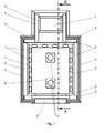
- the firing device has a combustion chamber 6, which is provided on three sides with heat-resistant metal tubes 1, which have an oval cross-section and - as out Fig. 2 can be seen - are provided with directed against the interior of the combustion chamber 6, with respect to the horizontal plane differently inclined outlet ports 13 for a supply of air. Furthermore, the combustion chamber 6 is surrounded with heat-resistant insulation boards 2 and provided with an oven door 5, via the solid fuel such as wood, can be supplied.
- insulation panels 2 are externally provided with chamotte plates 3, which in turn are surrounded by an outer shell 4 of tiles or fireclay.
- the bottom of the combustion chamber 6 is formed by a heat-resistant plate 9, which simultaneously defines in connection with the outer shell 4, an air chamber 11 for air distribution with another plate 12, which communicates via an air inlet opening, not shown, with the room air.
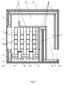
- the tubes 1 extend to the upper boundary of the combustion chamber 6, which is bounded above by a flue gas guide 8. But it is also possible to surround each tube at the back with a molded block, which also includes the tube above to protect it. In this case, then a small distance between the upper end of the tubes and the upper boundary of the combustion chamber is unavoidable.
- the flue gas guide 8 is formed by heat-resistant insulation boards 2 and leads to a lintel 7, through which the flue gases go down to a flue gas opening 14, to which a heat exchanger can be connected. In this way, there is a long post-combustion zone despite low space requirements.
- air passes to the glowing nest lying on the plate 9 via the air chamber 11 and the tubes 1 or their outlet openings 13 and enables a corresponding combustion of a solid fuel. It comes in the tubes 1 (and to a lesser extent in the air chamber 11) to preheat the air.
- the flame forming in the combustion process is also supplied with air in the higher regions of the combustion chamber 6 via the outlet openings 13, and also the region above the flame is supplied with air via the outlet openings 13, whereby the flue gases forming are burned and their CO Content is thus largely eliminated.
- a cooling of the flue gases is largely avoided by the insulation boards, whereby the afterburning is promoted.
- the flue gases are not cooled too much by the still cold fireclay.
- the carbon monoxide content in the main firing phase can be consistently kept below 10 ppm.
- the carbon monoxide content during the main fire phase was at times so low that it was below the detection limit of the measuring instrument used; he was with these Times therefore maximum 1 ppm.
- These short tubes are usually shorter than 10 cm, in the mentioned experiment they had a diameter of 50 mm and were 60 mm high (within the combustion chamber 6). With a larger combustion chamber and four such tubes can be provided.
Landscapes
- Engineering & Computer Science (AREA)
- Chemical & Material Sciences (AREA)
- Combustion & Propulsion (AREA)
- Mechanical Engineering (AREA)
- General Engineering & Computer Science (AREA)
- Physics & Mathematics (AREA)
- Thermal Sciences (AREA)
- Combustion Of Fluid Fuel (AREA)
- Solid-Fuel Combustion (AREA)
- Vertical, Hearth, Or Arc Furnaces (AREA)
Abstract
Description
- Die Erfindung bezieht sich auf eine Feuerungseinrichtung gemäß dem Oberbegriff des Anspruchs 1.
- Eine solche Einrichtung wurde z.B. durch die
DE 3927378 A bekannt. Bei dieser bekannten Feuerungseinrichtung sind Lufteinlässe für die Zufuhr von Primärluft, die über einen Vorwärmraum und eine Umlenkung zu einem Glutnest strömt, und von Sekundärluft vorgesehen. Dabei durchströmt die Sekundärluft die Luftkammer, steigt in der Luftführung, die teilweise zentral im Brennraum verläuft, nach oben und strömt schließlich über die Auslassöffnungen zum Glutnest und in die Flamme und in den an diese anschließenden Bereich. Dadurch kommt es auch zu einer gewissen Nachverbrennung der Rauchgase und damit zu einer Reduzierung des CO-Gehaltes der Rauchgase. - Bei dieser bekannten Feuerungseinrichtung ergibt sich der Nachteil, dass die Luftführung für die Sekundärluft einer sehr hohen Temperaturbelastung ausgesetzt ist, da sie zu einem beträchtlichen Teil in der Flammenzone verläuft, und dass die Sekundärluft aufgrund der nur geringen gesamten Querschnittsfläche der Auslassöffnungen mit hoher Geschwindigkeit ausströmt, was zu einer Störung der Flamme führen kann. Außerdem kann kaum eine für ein weitgehend vollständiges Ausbrennen der Rauchgase ausreichende Menge an Sekundärluft zugeführt werden.
- Ziel der Erfindung ist es, diese Nachteile zu vermeiden und eine Feuerungseinrichtung der eingangs erwähnten Art vorzuschlagen, die sich durch einen einfachen Aufbau auszeichnet und bei der eine noch vollständigere Verbrennung sichergestellt ist.
- Erfindungsgemäß wird dies bei einer Feuerungseinrichtung der eingangs erwähnten Art durch die kennzeichnenden Merkmale des Anspruchs 1 erreicht.
- Da die Rohre am Umfang verteilt angeordnet sind (und kein Rohr zentral verläuft wie bei der
DE 3927378 A , ist die Temperaturbelastung signifikant reduziert. Dabei ist auch eine ausreichende Luftzufuhr auf sehr einfache Weise zu erreichen, wobei eine gleichmäßige Verteilung der Luft im Brennraum sichergestellt ist. Außerdem ist auch eine weitgehende Vorwärmung der Luft sichergestellt. - Es ist zweckmäßig, wenn die Rohre möglichst über den gesamten Umfang verteilt sind, soweit dies technisch möglich ist. Dies ist normalerweise überall möglich, ausgenommen im Bereich der Ofentüre. In diesem Sinne sind die Merkmale des Anspruchs 2 zweckmäßig.
- Durch die Merkmale des Anspruchs 3 ergibt sich der Vorteil, dass dem obersten Bereich der Flamme und dem an diesen anschließenden Bereich der Rauchgase ausreichend Luft zugeführt werden kann, um ein sehr weitgehendes Ausbrennen der Rauchgase sicherzustellen, ohne sehr aufwändige Rauchgaszüge vorsehen zu müssen.
- Durch die Merkmale des Anspruchs 4 wird eine besonders gleichmäßige Durchmischung der zugeführten Luft mit den Abgasen erreicht. Die Düsen können insbesondere abwechselnd nach oben und nach unten gerichtet sein.
- Durch die Merkmale der Ansprüche 5 und 6 wird eine hohe Temperatur der Rauchgase - insbesondere auch in der Startphase der Verbrennung - erzielt, und es ergibt sich in der Nachverbrennungszone eine über den Querschnitt im Wesentlichen gleichmäßige Temperaturverteilung, wodurch ein im Wesentlichen vollständiges Ausbrennen der Rauchgase und damit ein sehr geringer CO-Gehalt derselben sichergestellt ist. Außerdem wird dadurch auch ein hohes Temperaturniveau der Rauchgase für einen nachgeschalteten Wärmetauscher erreicht.
- Durch die Merkmale des Anspruchs 7 ergibt sich trotz geringen Platzbedarfs eine lange Nachverbrennungszone. Bei einem Sturzzug werden die Rauchgase nach unten geführt. Wenn genügend Platz zur Verfügung steht, können die Rauchgase in der Nachverbrennungszone aber auch in anderen Richtungen, z.B. nach oben, geführt werden, ohne dass dies zu einer Verschlechterung der Abgaswerte führt.
- Durch die Maßnahmen von Anspruch 8 ist es möglich, auf eine getrennte Führung von Primär- und Sekundärluft zu verzichten, und es ist auch lediglich eine Lufteinlassöffnung für die Zufuhr von Luft zum Brennraum erforderlich.
- Es ist aber auch möglich, dass innerhalb des Umfangs des Grundrisses des Brennraums zumindest ein weiteres Rohr mit einer Höhe von weniger als 20 cm, vorzugsweise weniger als 15 cm, vorgesehen ist. Durch solch zusätzliche Rohre wird der CO-Gehalt noch weiter reduziert. Da diese Rohre relativ kurz sind, ist die mechanische Stabilität unkritisch und auch eine hohe thermische Belastung kein Problem.
- Die Erfindung wird nun anhand der Zeichnung näher erläutert. Dabei zeigt:
-
Fig. 1 einen Schnitt parallel zur Grundfläche einer erfindungsgemäßen Feuerungseinrichtung und -
Fig. 2 einen Schnitt entlang der Linie A-B inFig. 1 . - Die erfindungsgemäße Feuerungseinrichtung weist einen Brennraum 6 auf, der an drei Seiten mit hitzefesten Metallrohren 1 versehen ist, die einen ovalen Querschnitt aufweisen und - wie aus
Fig. 2 zu ersehen ist - mit gegen das Innere des Brennraumes 6 gerichteten, bezüglich der Horizontalebene unterschiedlich geneigten Auslassöffnungen 13 für eine Zufuhr von Luft versehen sind. Weiters ist der Brennraum 6 mit hitzefesten Dämmplatten 2 umgeben und mit einer Ofentür 5 versehen, über die fester Brennstoff, wie z.B. Holz, zugeführt werden kann. - Diese Dämmplatten 2 sind außen mit Schamotteplatten 3 versehen, die ihrerseits von einer Außenhülle 4 aus Kacheln oder Schamott umgeben sind.
- Der Boden des Brennraumes 6 ist durch eine hitzebeständige Platte 9 gebildet, die mit einer weiteren Platte 12 gleichzeitig in Verbindung mit der Außenhülle 4 eine Luftkammer 11 zur Luftverteilung begrenzt, die über eine nicht dargestellte Lufteinlassöffnung mit der Raumluft in Verbindung steht.
- In diese Luftkammer 11 ragen die hitzefesten Rohre 1 hinein, die an ihrem unteren Ende Lufteinströmöffnungen 10 aufweisen. Wie aus
Fig. 2 ersichtlich ist, reichen die Rohre 1 bis zur oberen Begrenzung des Brennraumes 6, der oben durch eine Rauchgasführung 8 begrenzt ist. Es ist aber auch möglich, jedes Rohr an der Rückseite mit einem Formstein zu umgeben, der das Rohr auch oben umfasst, um dieses zu schützen. In diesem Fall ist dann ein geringer Abstand zwischen dem oberen Ende der Rohre und der oberen Begrenzung des Brennraumes unvermeidbar. - Die Rauchgasführung 8 ist durch hitzefeste Dämmplatten 2 gebildet und führt zu einem Sturzzug 7, über den die Rauchgase nach unten zu einer Rauchgasöffnung 14 gelangen, an die ein Wärmetauscher angeschlossen werden kann. Auf diese Weise ergibt sich eine lange Nachverbrennungszone trotz geringen Platzbedarfs.
- Beim Betrieb der Feuerungseinrichtung gelangt Luft zum auf der Platte 9 liegenden Glutnest über die Luftkammer 11 und die Rohre 1 bzw. deren Auslassöffnungen 13 und ermöglicht eine entsprechende Verbrennung eines festen Brennstoffs. Dabei kommt es in den Rohren 1 (und in geringerem Ausmaß in der Luftkammer 11) zu einer Vorwärmung der Luft.
- Weiters wird auch der sich bei der Verbrennung ausbildenden Flamme Luft in den höheren Bereichen des Brennraumes 6 über die Auslassöffnungen 13 zugeführt, und auch der oberhalb der Flamme liegende Bereich wird mit Luft über die Auslassöffnungen 13 versorgt, wodurch die sich bildenden Rauchgase nachverbrannt und deren CO-Gehalt damit weitestgehend eliminiert wird. Dabei ist durch die Dämmplatten eine Abkühlung der Rauchgase weitgehend vermieden, wodurch die Nachverbrennung gefördert wird. Auch in der Startphase werden die Rauchgase durch den noch kalten Schamott nicht zu stark abgekühlt.
- Mit diesem Ofen kann der Kohlenmonoxidgehalt in der Hauptbrandphase durchgehend auf unter 10 ppm gehalten werden. Bei einem Versuch, wo zwei weitere kurze Rohre 15 innerhalb des Umfangs des Brennraums 7 vorgesehen waren, war der Kohlenmonoxidgehalt während der Hauptbrandphase zeitweise so gering, dass er unter der Erfassungsgrenze des verwendeten Messgeräts lag; er war zu diesen Zeiten daher maximal 1 ppm. Diese kurzen Rohre sind meist kürzer als 10 cm, bei dem erwähnten Versuch hatten Sie einen Durchmesser von 50 mm und waren 60 mm hoch (innerhalb des Brennraums 6). Bei einem größeren Brennraum können auch vier derartige Rohre vorgesehen werden.
- Besonders zu erwähnen ist, dass diese gute Verbrennung ohne motorgesteuerte Verbrennungsluftregelung, ohne Zugluftventilator (weder primär noch sekundär) und ohne Rauchgassauger erreicht wird.
Claims (9)
- Feuerungseinrichtung, insbesondere für Stückbrennstoff, mit einem Brennraum (6) und einer Luftzufuhr, wobei unter einem Boden einer Brennstoffaufnahme eine mit einem Lufteinlass verbundene Luftkammer (11) vorgesehen ist, von der aus eine nach oben ragende Luftführung mit Auslassöffnungen (13) wegführt, dadurch gekennzeichnet, dass die Luftzuführung durch eine Mehrzahl von nach oben führenden, über den Großteil des Umfanges des Grundrisses des Brennraumes (6) verteilt angeordneten Rohren (1) gebildet ist, von denen jedes mit der Luftkammer (11) in Verbindung steht und mit einer Mehrzahl von über die Höhe des Rohres (1) verteilt angeordneten und gegen den Brennraum (6) gerichteten Auslassöffnungen (13) versehen ist.
- Feuerungseinrichtung nach Anspruch 1, dadurch gekennzeichnet, dass die Rohre (1) im Wesentlichen über den gesamten Umfang des Brennraums (6) mit Ausnahme des Bereichs der Ofentüre verteilt angeordnet sind.
- Feuerungseinrichtung nach Anspruch 1 oder 2, dadurch gekennzeichnet, dass sich die Rohre (1) im Wesentlichen über die gesamte Höhe des Brennraumes (6) erstrecken und die Auslassöffnungen (13) im Wesentlichen über die gesamte Höhe der Rohre (1) verteilt angeordnet sind.
- Feuerungseinrichtung nach einem der Ansprüche 1 bis 3, dadurch gekennzeichnet, dass die Auslassöffnungen (13) als Düsen ausgebildet sind, die gegenüber der Horizontalebene in unterschiedlichen Winkeln gerichtet sind.
- Feuerungseinrichtung nach einem der Ansprüche 1 bis 4, dadurch gekennzeichnet, dass der obere Bereich des Brennraums (6) mit Dämmplatten (2) ausgekleidet ist.
- Feuerungseinrichtung nach einem der Ansprüche 1 bis 5, dadurch gekennzeichnet, dass an den Brennraum (6) eine Nachverbrennungszone anschließt, die mit Dämmplatten (2) ausgekleidet ist.
- Feuerungseinrichtung nach Anspruch 6, dadurch gekennzeichnet, dass die Nachverbrennungszone durch eine Rauchgasführung (8) oberhalb des Brennraums (6) und einen an diese anschließenden Sturzzug (7) gebildet ist.
- Feuerungseinrichtung nach einem der Ansprüche 1 bis 7, dadurch gekennzeichnet, dass die Luftzufuhr ausschließlich durch die über den Großteil des Umfanges des Grundrisses des Brennraumes (6) verteilt angeordneten Rohre (1) erfolgt.
- Feuerungseinrichtung nach einem der Ansprüche 1 bis 7, dadurch gekennzeichnet, dass innerhalb des Umfangs des Grundrisses des Brennraums zumindest ein weiteres Rohr (15), das mit der Luftkammer (11) verbunden ist und eine Höhe von weniger als 20 cm, vorzugsweise weniger als 15 cm aufweist, zur Luftzufuhr vorgesehen ist.
Applications Claiming Priority (1)
| Application Number | Priority Date | Filing Date | Title |
|---|---|---|---|
| ATA50471/2014A AT515113B1 (de) | 2014-07-04 | 2014-07-04 | Feuerungseinrichtung |
Publications (3)
| Publication Number | Publication Date |
|---|---|
| EP2966358A2 true EP2966358A2 (de) | 2016-01-13 |
| EP2966358A3 EP2966358A3 (de) | 2016-09-21 |
| EP2966358B1 EP2966358B1 (de) | 2024-07-17 |
Family
ID=53373161
Family Applications (1)
| Application Number | Title | Priority Date | Filing Date |
|---|---|---|---|
| EP15175043.7A Active EP2966358B1 (de) | 2014-07-04 | 2015-07-02 | Feuerungseinrichtung |
Country Status (2)
| Country | Link |
|---|---|
| EP (1) | EP2966358B1 (de) |
| AT (1) | AT515113B1 (de) |
Citations (1)
| Publication number | Priority date | Publication date | Assignee | Title |
|---|---|---|---|---|
| DE3927378A1 (de) | 1989-08-19 | 1991-02-21 | Diederichs Hans Joachim | Feuerungsvorrichtung |
Family Cites Families (8)
| Publication number | Priority date | Publication date | Assignee | Title |
|---|---|---|---|---|
| CH240716A (de) * | 1943-10-04 | 1946-01-15 | Wartburg Wilhelm Von | Vorrichtung zur Verbesserung des Heizeffektes von Heizanlagen. |
| DE1760311U (de) * | 1957-03-06 | 1958-01-23 | Rio Lange | Rauchgas-verbrenner. |
| FR2542849B1 (fr) * | 1983-03-18 | 1985-12-13 | Telec 2000 | Installation de chauffage domestique a foyer ferme utilisant un combustible solide du type bois ou ses derives |
| IT1173858B (it) * | 1983-03-18 | 1987-06-24 | Telec 2000 Srl Soc | Impianto di riscaldamento domestico a focolare chiuso utilizzante un combustibile solido tipo legno o suoi derivati |
| DE29504710U1 (de) * | 1995-03-24 | 1995-05-04 | Hock, Hans-Joachim, 67098 Bad Dürkheim | Einsatzkörper für Feuerstätten |
| DE20011685U1 (de) * | 2000-07-05 | 2001-02-22 | Bergholz, Günter, 44269 Dortmund | Kamineinsatz für häusliche Feuerstätten |
| DE102008011167A1 (de) * | 2008-02-26 | 2009-08-27 | Ulrich Baumann | Heizofen zum Beheizen des Raumes eines Wohn-Gebäudes |
| ITPN20100021U1 (it) * | 2010-10-25 | 2012-04-26 | Mcz Group S P A | Apparecchiatura di riscaldamento a combustibile solido |
-
2014
- 2014-07-04 AT ATA50471/2014A patent/AT515113B1/de active
-
2015
- 2015-07-02 EP EP15175043.7A patent/EP2966358B1/de active Active
Patent Citations (1)
| Publication number | Priority date | Publication date | Assignee | Title |
|---|---|---|---|---|
| DE3927378A1 (de) | 1989-08-19 | 1991-02-21 | Diederichs Hans Joachim | Feuerungsvorrichtung |
Also Published As
| Publication number | Publication date |
|---|---|
| AT515113B1 (de) | 2015-06-15 |
| AT515113A4 (de) | 2015-06-15 |
| EP2966358B1 (de) | 2024-07-17 |
| EP2966358A3 (de) | 2016-09-21 |
Similar Documents
| Publication | Publication Date | Title |
|---|---|---|
| EP0510783B1 (de) | Vorrichtung zur Verbrennung von fliessfähigen oder gasförmigen Brennstoffen | |
| DE102009053755A1 (de) | Verfahren und Vorrichtung zum Schmelzen von Glas | |
| AT409892B (de) | Heizeinrichtung für feste brennstoffe, insbesondere kompaktofen bzw. kamineinsatz | |
| AT515113B1 (de) | Feuerungseinrichtung | |
| DE3705153C2 (de) | ||
| DE1803985A1 (de) | Waermegenerator,insbesondere Winderhitzer fuer Hochoefen | |
| AT397554B (de) | Vorrichtung zum verbrennen fester brennstoffe, insbesondere holz | |
| DE3916142C2 (de) | Atmosphärischer Gasbrenner | |
| EP0062231B1 (de) | Gasbeheizter Backofen mit Umwälzventilator | |
| DE3503553C2 (de) | ||
| DE102006032497B4 (de) | Holzofen | |
| AT505770B1 (de) | Holzofen | |
| DE3503554C2 (de) | ||
| DE1164059B (de) | Waermestrahler mit flammenloser Oberflaechenverbrennung, insbesondere zur Raumheizung | |
| DE2114192C3 (de) | Raumheizofen | |
| DE2459502A1 (de) | Feuerung mit wenigstens einem in einer brennkammer oder einem ofenraum angeordneten brenner | |
| DE19537843A1 (de) | Zuluftverteilungseinrichtung für die Verbrennungsluft von Heizeinrichtungen, insbesondere für Festbrennstoffe sowie Verfahren zum Zuführen von Verbrennungsluft | |
| DE3927378A1 (de) | Feuerungsvorrichtung | |
| AT201211B (de) | Schmelzkammerfeuerung | |
| DE3830884C2 (de) | ||
| EP3324122B1 (de) | Kaminofen | |
| DE745553C (de) | Tunnelofen mit seitlich vom Erhitzungsraum laengs der Seiten der Heizzone angeordneten Brennkammern | |
| EP0320924A2 (de) | Heizkessel mit einem Brenner für feste Brennstoffe | |
| DE1451428B1 (de) | Fluessigstoffbrenner fuer metallurgische OEfen | |
| DE2448235A1 (de) | Brenner mit durch die verbrennung erzeugter direkter erwaermung eines mediums |
Legal Events
| Date | Code | Title | Description |
|---|---|---|---|
| PUAI | Public reference made under article 153(3) epc to a published international application that has entered the european phase |
Free format text: ORIGINAL CODE: 0009012 |
|
| AK | Designated contracting states |
Kind code of ref document: A2 Designated state(s): AL AT BE BG CH CY CZ DE DK EE ES FI FR GB GR HR HU IE IS IT LI LT LU LV MC MK MT NL NO PL PT RO RS SE SI SK SM TR |
|
| AX | Request for extension of the european patent |
Extension state: BA ME |
|
| PUAL | Search report despatched |
Free format text: ORIGINAL CODE: 0009013 |
|
| AK | Designated contracting states |
Kind code of ref document: A3 Designated state(s): AL AT BE BG CH CY CZ DE DK EE ES FI FR GB GR HR HU IE IS IT LI LT LU LV MC MK MT NL NO PL PT RO RS SE SI SK SM TR |
|
| AX | Request for extension of the european patent |
Extension state: BA ME |
|
| RIC1 | Information provided on ipc code assigned before grant |
Ipc: F23L 9/06 20060101ALI20160816BHEP Ipc: F23B 80/04 20060101ALI20160816BHEP Ipc: F23B 90/04 20110101ALI20160816BHEP Ipc: F24B 5/02 20060101AFI20160816BHEP Ipc: F23L 9/02 20060101ALI20160816BHEP |
|
| STAA | Information on the status of an ep patent application or granted ep patent |
Free format text: STATUS: REQUEST FOR EXAMINATION WAS MADE |
|
| 17P | Request for examination filed |
Effective date: 20170301 |
|
| RBV | Designated contracting states (corrected) |
Designated state(s): AL AT BE BG CH CY CZ DE DK EE ES FI FR GB GR HR HU IE IS IT LI LT LU LV MC MK MT NL NO PL PT RO RS SE SI SK SM TR |
|
| STAA | Information on the status of an ep patent application or granted ep patent |
Free format text: STATUS: EXAMINATION IS IN PROGRESS |
|
| 17Q | First examination report despatched |
Effective date: 20190318 |
|
| GRAP | Despatch of communication of intention to grant a patent |
Free format text: ORIGINAL CODE: EPIDOSNIGR1 |
|
| STAA | Information on the status of an ep patent application or granted ep patent |
Free format text: STATUS: GRANT OF PATENT IS INTENDED |
|
| INTG | Intention to grant announced |
Effective date: 20200303 |
|
| GRAJ | Information related to disapproval of communication of intention to grant by the applicant or resumption of examination proceedings by the epo deleted |
Free format text: ORIGINAL CODE: EPIDOSDIGR1 |
|
| STAA | Information on the status of an ep patent application or granted ep patent |
Free format text: STATUS: EXAMINATION IS IN PROGRESS |
|
| INTG | Intention to grant announced |
Effective date: 20200303 |
|
| APBK | Appeal reference recorded |
Free format text: ORIGINAL CODE: EPIDOSNREFNE |
|
| APBN | Date of receipt of notice of appeal recorded |
Free format text: ORIGINAL CODE: EPIDOSNNOA2E |
|
| APBR | Date of receipt of statement of grounds of appeal recorded |
Free format text: ORIGINAL CODE: EPIDOSNNOA3E |
|
| APAF | Appeal reference modified |
Free format text: ORIGINAL CODE: EPIDOSCREFNE |
|
| APBT | Appeal procedure closed |
Free format text: ORIGINAL CODE: EPIDOSNNOA9E |
|
| GRAJ | Information related to disapproval of communication of intention to grant by the applicant or resumption of examination proceedings by the epo deleted |
Free format text: ORIGINAL CODE: EPIDOSDIGR1 |
|
| GRAP | Despatch of communication of intention to grant a patent |
Free format text: ORIGINAL CODE: EPIDOSNIGR1 |
|
| STAA | Information on the status of an ep patent application or granted ep patent |
Free format text: STATUS: GRANT OF PATENT IS INTENDED |
|
| INTC | Intention to grant announced (deleted) | ||
| INTG | Intention to grant announced |
Effective date: 20240202 |
|
| GRAS | Grant fee paid |
Free format text: ORIGINAL CODE: EPIDOSNIGR3 |
|
| GRAA | (expected) grant |
Free format text: ORIGINAL CODE: 0009210 |
|
| STAA | Information on the status of an ep patent application or granted ep patent |
Free format text: STATUS: THE PATENT HAS BEEN GRANTED |
|
| AK | Designated contracting states |
Kind code of ref document: B1 Designated state(s): AL AT BE BG CH CY CZ DE DK EE ES FI FR GB GR HR HU IE IS IT LI LT LU LV MC MK MT NL NO PL PT RO RS SE SI SK SM TR |
|
| REG | Reference to a national code |
Ref country code: GB Ref legal event code: FG4D Free format text: NOT ENGLISH |
|
| REG | Reference to a national code |
Ref country code: CH Ref legal event code: EP |
|
| REG | Reference to a national code |
Ref country code: DE Ref legal event code: R096 Ref document number: 502015016902 Country of ref document: DE |
|
| REG | Reference to a national code |
Ref country code: IE Ref legal event code: FG4D Free format text: LANGUAGE OF EP DOCUMENT: GERMAN |
|
| REG | Reference to a national code |
Ref country code: SE Ref legal event code: TRGR |
|
| REG | Reference to a national code |
Ref country code: LT Ref legal event code: MG9D |
|
| REG | Reference to a national code |
Ref country code: NL Ref legal event code: MP Effective date: 20240717 |
|
| PG25 | Lapsed in a contracting state [announced via postgrant information from national office to epo] |
Ref country code: PT Free format text: LAPSE BECAUSE OF FAILURE TO SUBMIT A TRANSLATION OF THE DESCRIPTION OR TO PAY THE FEE WITHIN THE PRESCRIBED TIME-LIMIT Effective date: 20241118 |
|
| PG25 | Lapsed in a contracting state [announced via postgrant information from national office to epo] |
Ref country code: NL Free format text: LAPSE BECAUSE OF FAILURE TO SUBMIT A TRANSLATION OF THE DESCRIPTION OR TO PAY THE FEE WITHIN THE PRESCRIBED TIME-LIMIT Effective date: 20240717 |
|
| PG25 | Lapsed in a contracting state [announced via postgrant information from national office to epo] |
Ref country code: PT Free format text: LAPSE BECAUSE OF FAILURE TO SUBMIT A TRANSLATION OF THE DESCRIPTION OR TO PAY THE FEE WITHIN THE PRESCRIBED TIME-LIMIT Effective date: 20241118 Ref country code: NL Free format text: LAPSE BECAUSE OF FAILURE TO SUBMIT A TRANSLATION OF THE DESCRIPTION OR TO PAY THE FEE WITHIN THE PRESCRIBED TIME-LIMIT Effective date: 20240717 |
|
| PG25 | Lapsed in a contracting state [announced via postgrant information from national office to epo] |
Ref country code: NO Free format text: LAPSE BECAUSE OF FAILURE TO SUBMIT A TRANSLATION OF THE DESCRIPTION OR TO PAY THE FEE WITHIN THE PRESCRIBED TIME-LIMIT Effective date: 20241017 |
|
| PG25 | Lapsed in a contracting state [announced via postgrant information from national office to epo] |
Ref country code: FI Free format text: LAPSE BECAUSE OF FAILURE TO SUBMIT A TRANSLATION OF THE DESCRIPTION OR TO PAY THE FEE WITHIN THE PRESCRIBED TIME-LIMIT Effective date: 20240717 Ref country code: PL Free format text: LAPSE BECAUSE OF FAILURE TO SUBMIT A TRANSLATION OF THE DESCRIPTION OR TO PAY THE FEE WITHIN THE PRESCRIBED TIME-LIMIT Effective date: 20240717 Ref country code: GR Free format text: LAPSE BECAUSE OF FAILURE TO SUBMIT A TRANSLATION OF THE DESCRIPTION OR TO PAY THE FEE WITHIN THE PRESCRIBED TIME-LIMIT Effective date: 20241018 |
|
| PG25 | Lapsed in a contracting state [announced via postgrant information from national office to epo] |
Ref country code: BG Free format text: LAPSE BECAUSE OF FAILURE TO SUBMIT A TRANSLATION OF THE DESCRIPTION OR TO PAY THE FEE WITHIN THE PRESCRIBED TIME-LIMIT Effective date: 20240717 |
|
| PG25 | Lapsed in a contracting state [announced via postgrant information from national office to epo] |
Ref country code: LV Free format text: LAPSE BECAUSE OF FAILURE TO SUBMIT A TRANSLATION OF THE DESCRIPTION OR TO PAY THE FEE WITHIN THE PRESCRIBED TIME-LIMIT Effective date: 20240717 |
|
| PG25 | Lapsed in a contracting state [announced via postgrant information from national office to epo] |
Ref country code: IS Free format text: LAPSE BECAUSE OF FAILURE TO SUBMIT A TRANSLATION OF THE DESCRIPTION OR TO PAY THE FEE WITHIN THE PRESCRIBED TIME-LIMIT Effective date: 20241117 |
|
| PG25 | Lapsed in a contracting state [announced via postgrant information from national office to epo] |
Ref country code: HR Free format text: LAPSE BECAUSE OF FAILURE TO SUBMIT A TRANSLATION OF THE DESCRIPTION OR TO PAY THE FEE WITHIN THE PRESCRIBED TIME-LIMIT Effective date: 20240717 |
|
| PG25 | Lapsed in a contracting state [announced via postgrant information from national office to epo] |
Ref country code: ES Free format text: LAPSE BECAUSE OF FAILURE TO SUBMIT A TRANSLATION OF THE DESCRIPTION OR TO PAY THE FEE WITHIN THE PRESCRIBED TIME-LIMIT Effective date: 20240717 Ref country code: RS Free format text: LAPSE BECAUSE OF FAILURE TO SUBMIT A TRANSLATION OF THE DESCRIPTION OR TO PAY THE FEE WITHIN THE PRESCRIBED TIME-LIMIT Effective date: 20241017 |
|
| PG25 | Lapsed in a contracting state [announced via postgrant information from national office to epo] |
Ref country code: RS Free format text: LAPSE BECAUSE OF FAILURE TO SUBMIT A TRANSLATION OF THE DESCRIPTION OR TO PAY THE FEE WITHIN THE PRESCRIBED TIME-LIMIT Effective date: 20241017 Ref country code: PL Free format text: LAPSE BECAUSE OF FAILURE TO SUBMIT A TRANSLATION OF THE DESCRIPTION OR TO PAY THE FEE WITHIN THE PRESCRIBED TIME-LIMIT Effective date: 20240717 Ref country code: NO Free format text: LAPSE BECAUSE OF FAILURE TO SUBMIT A TRANSLATION OF THE DESCRIPTION OR TO PAY THE FEE WITHIN THE PRESCRIBED TIME-LIMIT Effective date: 20241017 Ref country code: LV Free format text: LAPSE BECAUSE OF FAILURE TO SUBMIT A TRANSLATION OF THE DESCRIPTION OR TO PAY THE FEE WITHIN THE PRESCRIBED TIME-LIMIT Effective date: 20240717 Ref country code: IS Free format text: LAPSE BECAUSE OF FAILURE TO SUBMIT A TRANSLATION OF THE DESCRIPTION OR TO PAY THE FEE WITHIN THE PRESCRIBED TIME-LIMIT Effective date: 20241117 Ref country code: HR Free format text: LAPSE BECAUSE OF FAILURE TO SUBMIT A TRANSLATION OF THE DESCRIPTION OR TO PAY THE FEE WITHIN THE PRESCRIBED TIME-LIMIT Effective date: 20240717 Ref country code: GR Free format text: LAPSE BECAUSE OF FAILURE TO SUBMIT A TRANSLATION OF THE DESCRIPTION OR TO PAY THE FEE WITHIN THE PRESCRIBED TIME-LIMIT Effective date: 20241018 Ref country code: FI Free format text: LAPSE BECAUSE OF FAILURE TO SUBMIT A TRANSLATION OF THE DESCRIPTION OR TO PAY THE FEE WITHIN THE PRESCRIBED TIME-LIMIT Effective date: 20240717 Ref country code: ES Free format text: LAPSE BECAUSE OF FAILURE TO SUBMIT A TRANSLATION OF THE DESCRIPTION OR TO PAY THE FEE WITHIN THE PRESCRIBED TIME-LIMIT Effective date: 20240717 Ref country code: BG Free format text: LAPSE BECAUSE OF FAILURE TO SUBMIT A TRANSLATION OF THE DESCRIPTION OR TO PAY THE FEE WITHIN THE PRESCRIBED TIME-LIMIT Effective date: 20240717 |
|
| PG25 | Lapsed in a contracting state [announced via postgrant information from national office to epo] |
Ref country code: RO Free format text: LAPSE BECAUSE OF FAILURE TO SUBMIT A TRANSLATION OF THE DESCRIPTION OR TO PAY THE FEE WITHIN THE PRESCRIBED TIME-LIMIT Effective date: 20240717 Ref country code: DK Free format text: LAPSE BECAUSE OF FAILURE TO SUBMIT A TRANSLATION OF THE DESCRIPTION OR TO PAY THE FEE WITHIN THE PRESCRIBED TIME-LIMIT Effective date: 20240717 Ref country code: SM Free format text: LAPSE BECAUSE OF FAILURE TO SUBMIT A TRANSLATION OF THE DESCRIPTION OR TO PAY THE FEE WITHIN THE PRESCRIBED TIME-LIMIT Effective date: 20240717 |
|
| REG | Reference to a national code |
Ref country code: DE Ref legal event code: R097 Ref document number: 502015016902 Country of ref document: DE |
|
| PG25 | Lapsed in a contracting state [announced via postgrant information from national office to epo] |
Ref country code: EE Free format text: LAPSE BECAUSE OF FAILURE TO SUBMIT A TRANSLATION OF THE DESCRIPTION OR TO PAY THE FEE WITHIN THE PRESCRIBED TIME-LIMIT Effective date: 20240717 |
|
| PG25 | Lapsed in a contracting state [announced via postgrant information from national office to epo] |
Ref country code: SK Free format text: LAPSE BECAUSE OF FAILURE TO SUBMIT A TRANSLATION OF THE DESCRIPTION OR TO PAY THE FEE WITHIN THE PRESCRIBED TIME-LIMIT Effective date: 20240717 |
|
| PLBE | No opposition filed within time limit |
Free format text: ORIGINAL CODE: 0009261 |
|
| STAA | Information on the status of an ep patent application or granted ep patent |
Free format text: STATUS: NO OPPOSITION FILED WITHIN TIME LIMIT |
|
| 26N | No opposition filed |
Effective date: 20250422 |
|
| PGFP | Annual fee paid to national office [announced via postgrant information from national office to epo] |
Ref country code: FR Payment date: 20250606 Year of fee payment: 11 |
|
| PGFP | Annual fee paid to national office [announced via postgrant information from national office to epo] |
Ref country code: CZ Payment date: 20250611 Year of fee payment: 11 |
|
| PGFP | Annual fee paid to national office [announced via postgrant information from national office to epo] |
Ref country code: SE Payment date: 20250610 Year of fee payment: 11 |
|
| PGFP | Annual fee paid to national office [announced via postgrant information from national office to epo] |
Ref country code: DE Payment date: 20250606 Year of fee payment: 11 |
|
| PG25 | Lapsed in a contracting state [announced via postgrant information from national office to epo] |
Ref country code: IT Free format text: LAPSE BECAUSE OF FAILURE TO SUBMIT A TRANSLATION OF THE DESCRIPTION OR TO PAY THE FEE WITHIN THE PRESCRIBED TIME-LIMIT Effective date: 20240717 |
|
| REG | Reference to a national code |
Ref country code: CH Ref legal event code: H13 Free format text: ST27 STATUS EVENT CODE: U-0-0-H10-H13 (AS PROVIDED BY THE NATIONAL OFFICE) Effective date: 20260224 |
|
| PG25 | Lapsed in a contracting state [announced via postgrant information from national office to epo] |
Ref country code: LU Free format text: LAPSE BECAUSE OF NON-PAYMENT OF DUE FEES Effective date: 20250702 |
|
| GBPC | Gb: european patent ceased through non-payment of renewal fee |
Effective date: 20250702 |
|
| REG | Reference to a national code |
Ref country code: BE Ref legal event code: MM Effective date: 20250731 |
|
| PG25 | Lapsed in a contracting state [announced via postgrant information from national office to epo] |
Ref country code: GB Free format text: LAPSE BECAUSE OF NON-PAYMENT OF DUE FEES Effective date: 20250702 |
|
| PG25 | Lapsed in a contracting state [announced via postgrant information from national office to epo] |
Ref country code: BE Free format text: LAPSE BECAUSE OF NON-PAYMENT OF DUE FEES Effective date: 20250731 |
|
| PG25 | Lapsed in a contracting state [announced via postgrant information from national office to epo] |
Ref country code: CH Free format text: LAPSE BECAUSE OF NON-PAYMENT OF DUE FEES Effective date: 20250731 |