EP2966384A1 - Dispositif de refroidissement d'un débit volumique d'eau potable - Google Patents
Dispositif de refroidissement d'un débit volumique d'eau potable Download PDFInfo
- Publication number
- EP2966384A1 EP2966384A1 EP15176242.4A EP15176242A EP2966384A1 EP 2966384 A1 EP2966384 A1 EP 2966384A1 EP 15176242 A EP15176242 A EP 15176242A EP 2966384 A1 EP2966384 A1 EP 2966384A1
- Authority
- EP
- European Patent Office
- Prior art keywords
- heat exchanger
- volume flow
- water volume
- drinking water
- connection
- Prior art date
- Legal status (The legal status is an assumption and is not a legal conclusion. Google has not performed a legal analysis and makes no representation as to the accuracy of the status listed.)
- Withdrawn
Links
Images


Classifications
-
- E—FIXED CONSTRUCTIONS
- E03—WATER SUPPLY; SEWERAGE
- E03B—INSTALLATIONS OR METHODS FOR OBTAINING, COLLECTING, OR DISTRIBUTING WATER
- E03B7/00—Water main or service pipe systems
- E03B7/04—Domestic or like local pipe systems
- E03B7/045—Domestic or like local pipe systems diverting initially cold water in warm water supply
-
- F—MECHANICAL ENGINEERING; LIGHTING; HEATING; WEAPONS; BLASTING
- F24—HEATING; RANGES; VENTILATING
- F24D—DOMESTIC- OR SPACE-HEATING SYSTEMS, e.g. CENTRAL HEATING SYSTEMS; DOMESTIC HOT-WATER SUPPLY SYSTEMS; ELEMENTS OR COMPONENTS THEREFOR
- F24D15/00—Other domestic- or space-heating systems
- F24D15/02—Other domestic- or space-heating systems consisting of self-contained heating units, e.g. storage heaters
-
- F—MECHANICAL ENGINEERING; LIGHTING; HEATING; WEAPONS; BLASTING
- F24—HEATING; RANGES; VENTILATING
- F24D—DOMESTIC- OR SPACE-HEATING SYSTEMS, e.g. CENTRAL HEATING SYSTEMS; DOMESTIC HOT-WATER SUPPLY SYSTEMS; ELEMENTS OR COMPONENTS THEREFOR
- F24D17/00—Domestic hot-water supply systems
- F24D17/02—Domestic hot-water supply systems using heat pumps
-
- F—MECHANICAL ENGINEERING; LIGHTING; HEATING; WEAPONS; BLASTING
- F24—HEATING; RANGES; VENTILATING
- F24D—DOMESTIC- OR SPACE-HEATING SYSTEMS, e.g. CENTRAL HEATING SYSTEMS; DOMESTIC HOT-WATER SUPPLY SYSTEMS; ELEMENTS OR COMPONENTS THEREFOR
- F24D19/00—Details
- F24D19/10—Arrangement or mounting of control or safety devices
- F24D19/1006—Arrangement or mounting of control or safety devices for water heating systems
- F24D19/1051—Arrangement or mounting of control or safety devices for water heating systems for domestic hot water
- F24D19/1054—Arrangement or mounting of control or safety devices for water heating systems for domestic hot water the system uses a heat pump
-
- F—MECHANICAL ENGINEERING; LIGHTING; HEATING; WEAPONS; BLASTING
- F25—REFRIGERATION OR COOLING; COMBINED HEATING AND REFRIGERATION SYSTEMS; HEAT PUMP SYSTEMS; MANUFACTURE OR STORAGE OF ICE; LIQUEFACTION SOLIDIFICATION OF GASES
- F25B—REFRIGERATION MACHINES, PLANTS OR SYSTEMS; COMBINED HEATING AND REFRIGERATION SYSTEMS; HEAT PUMP SYSTEMS
- F25B29/00—Combined heating and refrigeration systems, e.g. operating alternately or simultaneously
- F25B29/003—Combined heating and refrigeration systems, e.g. operating alternately or simultaneously of the compression type system
-
- C—CHEMISTRY; METALLURGY
- C02—TREATMENT OF WATER, WASTE WATER, SEWAGE, OR SLUDGE
- C02F—TREATMENT OF WATER, WASTE WATER, SEWAGE, OR SLUDGE
- C02F1/00—Treatment of water, waste water, or sewage
- C02F1/02—Treatment of water, waste water, or sewage by heating
-
- C—CHEMISTRY; METALLURGY
- C02—TREATMENT OF WATER, WASTE WATER, SEWAGE, OR SLUDGE
- C02F—TREATMENT OF WATER, WASTE WATER, SEWAGE, OR SLUDGE
- C02F2303/00—Specific treatment goals
- C02F2303/04—Disinfection
-
- C—CHEMISTRY; METALLURGY
- C02—TREATMENT OF WATER, WASTE WATER, SEWAGE, OR SLUDGE
- C02F—TREATMENT OF WATER, WASTE WATER, SEWAGE, OR SLUDGE
- C02F2307/00—Location of water treatment or water treatment device
- C02F2307/14—Treatment of water in water supply networks, e.g. to prevent bacterial growth
-
- F—MECHANICAL ENGINEERING; LIGHTING; HEATING; WEAPONS; BLASTING
- F24—HEATING; RANGES; VENTILATING
- F24D—DOMESTIC- OR SPACE-HEATING SYSTEMS, e.g. CENTRAL HEATING SYSTEMS; DOMESTIC HOT-WATER SUPPLY SYSTEMS; ELEMENTS OR COMPONENTS THEREFOR
- F24D17/00—Domestic hot-water supply systems
- F24D17/0073—Arrangements for preventing the occurrence or proliferation of microorganisms in the water
-
- F—MECHANICAL ENGINEERING; LIGHTING; HEATING; WEAPONS; BLASTING
- F24—HEATING; RANGES; VENTILATING
- F24D—DOMESTIC- OR SPACE-HEATING SYSTEMS, e.g. CENTRAL HEATING SYSTEMS; DOMESTIC HOT-WATER SUPPLY SYSTEMS; ELEMENTS OR COMPONENTS THEREFOR
- F24D17/00—Domestic hot-water supply systems
- F24D17/0078—Recirculation systems
-
- F—MECHANICAL ENGINEERING; LIGHTING; HEATING; WEAPONS; BLASTING
- F24—HEATING; RANGES; VENTILATING
- F24D—DOMESTIC- OR SPACE-HEATING SYSTEMS, e.g. CENTRAL HEATING SYSTEMS; DOMESTIC HOT-WATER SUPPLY SYSTEMS; ELEMENTS OR COMPONENTS THEREFOR
- F24D2200/00—Heat sources or energy sources
- F24D2200/12—Heat pump
- F24D2200/123—Compression type heat pumps
-
- F—MECHANICAL ENGINEERING; LIGHTING; HEATING; WEAPONS; BLASTING
- F24—HEATING; RANGES; VENTILATING
- F24D—DOMESTIC- OR SPACE-HEATING SYSTEMS, e.g. CENTRAL HEATING SYSTEMS; DOMESTIC HOT-WATER SUPPLY SYSTEMS; ELEMENTS OR COMPONENTS THEREFOR
- F24D2200/00—Heat sources or energy sources
- F24D2200/12—Heat pump
- F24D2200/126—Absorption type heat pumps
-
- F—MECHANICAL ENGINEERING; LIGHTING; HEATING; WEAPONS; BLASTING
- F24—HEATING; RANGES; VENTILATING
- F24D—DOMESTIC- OR SPACE-HEATING SYSTEMS, e.g. CENTRAL HEATING SYSTEMS; DOMESTIC HOT-WATER SUPPLY SYSTEMS; ELEMENTS OR COMPONENTS THEREFOR
- F24D2220/00—Components of central heating installations excluding heat sources
- F24D2220/02—Fluid distribution means
- F24D2220/025—Check valves
-
- F—MECHANICAL ENGINEERING; LIGHTING; HEATING; WEAPONS; BLASTING
- F25—REFRIGERATION OR COOLING; COMBINED HEATING AND REFRIGERATION SYSTEMS; HEAT PUMP SYSTEMS; MANUFACTURE OR STORAGE OF ICE; LIQUEFACTION SOLIDIFICATION OF GASES
- F25B—REFRIGERATION MACHINES, PLANTS OR SYSTEMS; COMBINED HEATING AND REFRIGERATION SYSTEMS; HEAT PUMP SYSTEMS
- F25B2339/00—Details of evaporators; Details of condensers
- F25B2339/04—Details of condensers
- F25B2339/047—Water-cooled condensers
-
- F—MECHANICAL ENGINEERING; LIGHTING; HEATING; WEAPONS; BLASTING
- F25—REFRIGERATION OR COOLING; COMBINED HEATING AND REFRIGERATION SYSTEMS; HEAT PUMP SYSTEMS; MANUFACTURE OR STORAGE OF ICE; LIQUEFACTION SOLIDIFICATION OF GASES
- F25B—REFRIGERATION MACHINES, PLANTS OR SYSTEMS; COMBINED HEATING AND REFRIGERATION SYSTEMS; HEAT PUMP SYSTEMS
- F25B25/00—Machines, plants or systems, using a combination of modes of operation covered by two or more of the groups F25B1/00 - F25B23/00
- F25B25/005—Machines, plants or systems, using a combination of modes of operation covered by two or more of the groups F25B1/00 - F25B23/00 using primary and secondary systems
-
- F—MECHANICAL ENGINEERING; LIGHTING; HEATING; WEAPONS; BLASTING
- F25—REFRIGERATION OR COOLING; COMBINED HEATING AND REFRIGERATION SYSTEMS; HEAT PUMP SYSTEMS; MANUFACTURE OR STORAGE OF ICE; LIQUEFACTION SOLIDIFICATION OF GASES
- F25B—REFRIGERATION MACHINES, PLANTS OR SYSTEMS; COMBINED HEATING AND REFRIGERATION SYSTEMS; HEAT PUMP SYSTEMS
- F25B2700/00—Sensing or detecting of parameters; Sensors therefor
- F25B2700/19—Pressures
- F25B2700/193—Pressures of the compressor
- F25B2700/1931—Discharge pressures
-
- F—MECHANICAL ENGINEERING; LIGHTING; HEATING; WEAPONS; BLASTING
- F25—REFRIGERATION OR COOLING; COMBINED HEATING AND REFRIGERATION SYSTEMS; HEAT PUMP SYSTEMS; MANUFACTURE OR STORAGE OF ICE; LIQUEFACTION SOLIDIFICATION OF GASES
- F25B—REFRIGERATION MACHINES, PLANTS OR SYSTEMS; COMBINED HEATING AND REFRIGERATION SYSTEMS; HEAT PUMP SYSTEMS
- F25B2700/00—Sensing or detecting of parameters; Sensors therefor
- F25B2700/19—Pressures
- F25B2700/193—Pressures of the compressor
- F25B2700/1933—Suction pressures
-
- F—MECHANICAL ENGINEERING; LIGHTING; HEATING; WEAPONS; BLASTING
- F25—REFRIGERATION OR COOLING; COMBINED HEATING AND REFRIGERATION SYSTEMS; HEAT PUMP SYSTEMS; MANUFACTURE OR STORAGE OF ICE; LIQUEFACTION SOLIDIFICATION OF GASES
- F25B—REFRIGERATION MACHINES, PLANTS OR SYSTEMS; COMBINED HEATING AND REFRIGERATION SYSTEMS; HEAT PUMP SYSTEMS
- F25B2700/00—Sensing or detecting of parameters; Sensors therefor
- F25B2700/21—Temperatures
- F25B2700/2115—Temperatures of a compressor or the drive means therefor
- F25B2700/21151—Temperatures of a compressor or the drive means therefor at the suction side of the compressor
-
- F—MECHANICAL ENGINEERING; LIGHTING; HEATING; WEAPONS; BLASTING
- F25—REFRIGERATION OR COOLING; COMBINED HEATING AND REFRIGERATION SYSTEMS; HEAT PUMP SYSTEMS; MANUFACTURE OR STORAGE OF ICE; LIQUEFACTION SOLIDIFICATION OF GASES
- F25B—REFRIGERATION MACHINES, PLANTS OR SYSTEMS; COMBINED HEATING AND REFRIGERATION SYSTEMS; HEAT PUMP SYSTEMS
- F25B2700/00—Sensing or detecting of parameters; Sensors therefor
- F25B2700/21—Temperatures
- F25B2700/2116—Temperatures of a condenser
- F25B2700/21161—Temperatures of a condenser of the fluid heated by the condenser
-
- F—MECHANICAL ENGINEERING; LIGHTING; HEATING; WEAPONS; BLASTING
- F25—REFRIGERATION OR COOLING; COMBINED HEATING AND REFRIGERATION SYSTEMS; HEAT PUMP SYSTEMS; MANUFACTURE OR STORAGE OF ICE; LIQUEFACTION SOLIDIFICATION OF GASES
- F25B—REFRIGERATION MACHINES, PLANTS OR SYSTEMS; COMBINED HEATING AND REFRIGERATION SYSTEMS; HEAT PUMP SYSTEMS
- F25B2700/00—Sensing or detecting of parameters; Sensors therefor
- F25B2700/21—Temperatures
- F25B2700/2117—Temperatures of an evaporator
- F25B2700/21171—Temperatures of an evaporator of the fluid cooled by the evaporator
- F25B2700/21173—Temperatures of an evaporator of the fluid cooled by the evaporator at the outlet
-
- F—MECHANICAL ENGINEERING; LIGHTING; HEATING; WEAPONS; BLASTING
- F25—REFRIGERATION OR COOLING; COMBINED HEATING AND REFRIGERATION SYSTEMS; HEAT PUMP SYSTEMS; MANUFACTURE OR STORAGE OF ICE; LIQUEFACTION SOLIDIFICATION OF GASES
- F25B—REFRIGERATION MACHINES, PLANTS OR SYSTEMS; COMBINED HEATING AND REFRIGERATION SYSTEMS; HEAT PUMP SYSTEMS
- F25B2700/00—Sensing or detecting of parameters; Sensors therefor
- F25B2700/21—Temperatures
- F25B2700/2117—Temperatures of an evaporator
- F25B2700/21174—Temperatures of an evaporator of the refrigerant at the inlet of the evaporator
-
- F—MECHANICAL ENGINEERING; LIGHTING; HEATING; WEAPONS; BLASTING
- F25—REFRIGERATION OR COOLING; COMBINED HEATING AND REFRIGERATION SYSTEMS; HEAT PUMP SYSTEMS; MANUFACTURE OR STORAGE OF ICE; LIQUEFACTION SOLIDIFICATION OF GASES
- F25B—REFRIGERATION MACHINES, PLANTS OR SYSTEMS; COMBINED HEATING AND REFRIGERATION SYSTEMS; HEAT PUMP SYSTEMS
- F25B2700/00—Sensing or detecting of parameters; Sensors therefor
- F25B2700/21—Temperatures
- F25B2700/2117—Temperatures of an evaporator
- F25B2700/21175—Temperatures of an evaporator of the refrigerant at the outlet of the evaporator
-
- F—MECHANICAL ENGINEERING; LIGHTING; HEATING; WEAPONS; BLASTING
- F28—HEAT EXCHANGE IN GENERAL
- F28D—HEAT-EXCHANGE APPARATUS, NOT PROVIDED FOR IN ANOTHER SUBCLASS, IN WHICH THE HEAT-EXCHANGE MEDIA DO NOT COME INTO DIRECT CONTACT
- F28D20/00—Heat storage plants or apparatus in general; Regenerative heat-exchange apparatus not covered by groups F28D17/00 or F28D19/00
- F28D20/0034—Heat storage plants or apparatus in general; Regenerative heat-exchange apparatus not covered by groups F28D17/00 or F28D19/00 using liquid heat storage material
Definitions
- DIN EN 806 and VDI guideline 6023 also call for limiting the temperature for cold drinking water to a maximum temperature of + 25 ° C, since from this temperature an increase in microbial growth is to be expected. In determining this temperature, however, it seems to be a compromise between technical feasibility and hygienic requirements, as recent studies show that a significant growth of microbes, especially of Legionella, already begins at significantly lower temperatures. For this reason, in the current VDI Guideline 6023 of April 2013 - in addition to limiting the temperature of cold drinking water to + 25 ° C - a recommendation should be made to keep the temperature of the water as low as possible below + 20 ° C.
- the EP 1 626 034 A1 in connection with the control of Legionella by means of chemical and / or electrolytic means also a circulation of the cold water before the consumption points before.
- the cold water in the circulation should also be cooled.
- the waste heat from cold water cooling is used to heat hot water. In this case, a cooling of the cold water to a temperature between 10 ° C and 15 ° C is proposed.
- the aforementioned object is achieved in that all components a) to i) are combined into a compact device and arranged on a common carrier and / or in a common housing.
- the device according to the invention thus contains all the necessary components which are required to operate a cooling of a "cold" drinking water volume flow to a temperature level which reliably prevents the growth of the legion.
- An effective preservation of the drinking water hygiene can be achieved accordingly with purely physical procedures with at the same time highest possible energy efficiency.
- all components contained in the device can be designed to match each other and guaranteeing an economic operation.
- the device according to the invention in different sizes with different efficient heat transfer modules, different sized heat exchangers and circulation circulation pumps and different sized connections, ie in particular line cross sections interpret and provide.
- the respective planner or builder thus has the opportunity to choose a suitable for his requirements model of the compact device according to the invention, without having to worry about the compilation of the individual components and their correct technical and economic operation.
- the device according to the invention thus saves planning and procurement costs and avoids the risk of incorrect design of individual components or the risk of incorrect assembly or interconnection of the components with each other. Furthermore, the expense of laying cables and installation on site is reduced because the components in the compact unit are already installed.
- the device according to the invention thus makes use of the principle of "plug and play" in order to make the installation and commissioning as easy as possible for the user.
- the device according to the invention also meets the increasingly important aesthetic demands of users, since the amount of visible lines is reduced to a minimum and the housing, in contrast to an individual interconnection of the individual components, especially in an arrangement of the components in a common housing may have attractive design.
- the device also has at least one non-return valve in a first strand containing the first port, a first portion of the first heat exchanger and the second port and / or in a third port, a first region of the second heat exchanger and the fourth terminal-containing second strand is arranged.
- Non-return valves are an easy way to prevent in the case of Zapf plantes a reversal of the flow direction in the circulation line. For this reason, it is advantageous to integrate these check valves immediately in the compact unit.
- a third heat exchanger which can be flowed through by the heated water volume flow, wherein preferably a heated by means of the third heat exchanger water volume flow is preferably deliverable from the fourth port.
- a compact device variant is suitable to continuously in a system with central hot water by means of a water heater according to the flow principle (often referred to as "fresh water station") the unheated, so “cold”, drinking water by means of the first heat exchanger to a desired target temperature to cool and use the resulting heat by means of the second heat transfer directly in the hot water circulation to cover the Auskühlmanne.
- the third heat exchanger contained in the variant described here serves as a hot water heater and must deliver at times without tapping only the residual heat required for the reheating of the circulating hot water.
- the second heat exchanger and the third heat exchanger in the hot water circulation pipe should preferably be arranged in series, i. can be flowed through in succession.
- a connecting line between a first strand, which contains the first port, the first heat exchanger and the second port, and a second strand, which contains the third port, the second heat exchanger and the fourth port is provided, preferably the connecting line of a Drinking water volume flow can be flowed through, the can then be heated in the third heat exchanger, the third heat exchanger also receives the function of a so-called fresh water station to cover in the case that hot water is tapped, the required heat demand for heating the drinking water to the desired hot water temperature level, the heat from a Heating system can be removed.
- the compact device should preferably also have a third circulating circulating pump, which is then typically a heating circulating pump with which heating water can be conveyed to the "warm side" of the third heat exchanger, which is not flown through by the warm drinking water.
- a check valve arranged in the connection line is provided, with which an overflow from the second strand into the first strand can be prevented.
- Such a check valve prevents a flow through the cold water circulation line in the direction opposite to the circulation operation when the third heat exchanger is used to provide hot water at a tap.
- heat from a heat transfer medium provided by a heating system in particular heating water
- the respectively required temperature increase of the hot water circulation or of the hot water flow to be taken is made possible by means of the third heat exchanger.
- the third heat exchanger can be part of a fresh water station in which a stream of drinking water flowing through the connecting line can be heated in a continuous flow
- the fresh water station preferably has a mixer with which the temperature of the heat-transferring heat transfer medium, preferably a Heating system comes from, is adjustable.
- the heat transfer medium in particular heating water, should preferably reach the third heat exchanger via a control valve, wherein the control valve should preferably be a mixing valve in the form of a three-way valve.
- a controller ensures that the adjustable setpoint temperature for the heated drinking water is maintained, in which the control valve adjusting stroke is changed.
- the control valve could be formed by a two-way valve instead of the three-way valve.
- the active heat transfer module is a compression refrigerating machine with a refrigerant circuit, wherein a second section of the first heat exchanger and a second section of the second heat exchanger are located in the refrigerant circuit and thermally coupled.
- the refrigerant should be compressed between the second portion and the second region by means of a compressor, in particular a piston compressor, and be expanded between the second region and the second portion by means of an expansion valve. To produce the required cooling capacity can thus be used on conventional and proven and therefore at low cost available refrigeration technology.
- the first heat exchanger which may be in the form of an evaporator, for example, can advantageously be divided into a first section through which drinking water flows and a second section through which refrigerant flows.
- the second heat exchanger for example a condenser, can be divided into a first area through which heating buffer water or heated drinking water flows and a second area through which refrigerant flows.
- the active heat transfer module can also be an absorption chiller or a Joule-Thomson effect chiller or a Peltier element or a magnetic cooling act.
- absorption chiller or a Joule-Thomson effect chiller or a Peltier element or a magnetic cooling act.
- connections of the compact unit are designed as threaded connections with internal thread or external thread or as conical fittings or for producing a clamping or crimping connection with incoming or outgoing pipes or lines or as a flange connection.
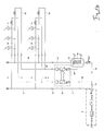
- FIG. 1a shows a system structure of a drinking water installation, the usual way a drinking water house connection 1, comprising (viewed in the flow direction) a first shut-off valve, a water meter, a second shut-off valve, a water filter, depending on the existing supply pressure, a pressure reducer, a third shut-off valve and a non-return valve.
- the above-mentioned individual components of the drinking water system connection are enclosed with a dot-dashed frame. That of a drinking water supplier provided cold drinking water has a temperature of about 10 ° Celsius when entering the house installation.
- the cold drinking water reaches a plurality of taps 6, which are located in the present case on two floors of a building, not shown. All of the aforementioned lines 2 to 5 are part of a cold water circulation line, to which the return of the cold drinking water from the taps 6 serving lines 7 , 8 , 9 , 10 and 11 belong. At times when no cold drinking water is removed at one of the taps 6 , thus the drinking water circulates through the aforementioned lines in the direction of arrows 12 .
- the system shown also has a hot water supply system, which starts from a hot water tank 13 in which a heat exchanger 14 is in the form of a shell and tube heat exchanger, which is traversed by heating water. On the underside of the hot water tank 13 flows via a branched off from the line 11 line 15 and a check valve 16 cold drinking water in the hot water tank 13 after.
- the inventive device 25 is enclosed in the form of a compact device with a running in dashed lines frame.
- the recirculated cold drinking water flows through the line 9 in the device 25 and leaves it through the line 10th
- the recirculated warm drinking water flows in via the line 23 and leaves the device 25 via the line 24 .
- the more detailed structure of the device 25 will be explained below.
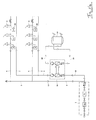
- FIG. 1 b An alternative system design of a drinking water installation without central hot water but with a decentralized hot water and a heating buffer memory shows the FIG. 1 b.
- the structure of the lines for the cold water extraction and circulation is identical to that in the system structure according to FIG. 1a , which is why it should not be discussed here.
- hot water is produced by means of instantaneous water heaters 26 , which are operated electrically or by gas and are assigned to each individual tapping point 6 .
- the installation according to FIG. 1b has a buffer memory 27 for heating water, which is connected via lines not shown to a heating system and supplied from there with heating water.
- a circulation line is further connected, which consists of a line 28 and a line 29 , both open into the buffer memory 27 and depart from this.
- the lines 9 and 10 through which cold drinking water flows lead into and out of the identically designed device 25 .
- the outgoing at the bottom of the buffer memory 27 line 28 leads into the device 25 and the opening at the top of the buffer memory 27 line 29 out of the device 25 out.
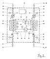
- the first heat exchanger W1 has two materially separated, but thermally interconnected portion 37 , 53 .
- the drinking water volume flow flowing through the "warm” section 37 and to be cooled is cooled by a refrigerant flowing through the "cold” section 53 and evaporating at the heat exchanger.
- the second heat exchanger W2 can also be divided into two regions 47 , 55 which are separated from one another but are thermally interconnected.
- the first "cold" area 47 is flowed through by a water volume flow, whereas the refrigerant is passed through the second "warm” area 55 .
- the water volume flow is in accordance with, circulated or heated drinking water FIG. 1a or around a heating buffer water circulating in the buffer memory 27 according to FIG FIG. 1 b.
- a heat transfer module 52 which is surrounded by a dash-dotted line, wherein the dash-dotted line framed by each flowed with refrigerant portion 53 of the heat exchanger W1 and portion 55 of the heat exchanger W2 .
- the heat transfer module 52 it is a compression refrigeration machine with a refrigerant evaporator formed by the first heat exchanger W1 , which extracts the heat from the cold drinking water to be cooled.
- the second section 53 of the first heat exchanger W1 is integrated in a refrigerant circuit of the heat transfer module 52 .
- the refrigerant leaving the heat exchanger W1 is compressed by means of a compressor 54 and then liquefied in the second region 55 of the heat exchanger W2 (in the form of a condenser in this embodiment).
- the refrigerant is subsequently expanded again via an adjustable expansion valve 56 , in order then to re-enter the gaseous phase in the second refrigerant-containing section 53 of the first heat exchanger W1 .
- the heat released during the liquefaction in the second heat exchanger W2 is transferred to the water volume flow in the first region 47 of the second heat exchanger W2 .
- control module 68 for example in the form of a microprocessor control / regulation, numerous options of the device 25 can be realized, such as a night reduction, different time programs and adjustable setpoints.
- temperature sensors pressure sensors may be connected to the inputs of the control module 68 .
- the control module 68, the first and second circulation circulation pump 36 and 46, the adjustable expansion valve 56 and the compressor 54 influence or regulate.
- connections 30 to 33 of the device 25 can be configured, for example, depending on the size, as threaded connections with internal or external pipe connection threads, as flange connections or as simple pipe ends for pressing.
- thermometers or control panels of the Pumps are typically cut out, so that a diagnosis without disassembly of the housing shell is possible.
- the housing many variants are conceivable, but do not change the basic structure of the components and their function. The size of the base plate and thus the entire unit depends on the size and will not be defined here.
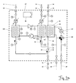
- FIG. 3 shown system structure of an alternative drinking water installation has - as the in FIG. 1 a system construction shown - a circulation line for both the cold drinking water and one for the warm drinking water on. Further explanations on this can therefore be dispensed with.
- the lines 9 and 10 as well as 23 and 24 adjoining the device 25 'deviating in terms of design are in this case identical even if they are arranged at other locations.
- the line 24 falls in the case of the embodiment according to FIG. 3 with the hot water supply line (line 17 in FIG. 1a ) together.
- the line 9 leads to the first terminal 30, the line 10 goes from the second terminal 31, leads the line 23 to the third terminal 32 and the line 24 is from the fourth terminal 33 from.
- the second variant of the device 25 ' has two further connections 57 and 58, which serve to supply heat transfer medium from the buffer memory 27 and the return of cooled heating buffer water from the device 25'.
- two lines 59 and 60 are connected to the terminals 57 and 58.
- the device 25 ' comprises a third heat exchanger W3 , which serves on the one hand, in times when no hot water is withdrawn to compensate for the circulation heat losses that can not be compensated by the second heat exchanger W2 . Due to the heat recovery that occurs during the cooling of the cold drinking water, however, the amount of heat to be supplied by the third heat exchanger W3 is lower than in the case without the heat recovery.
- the third heat exchanger W3 can be divided into two parts 61 , 66 , wherein a first "cold" part 61 with circulating drinking water or taps with cold drinking water, and a second "warm” part 66 with hot heat transfer medium, for example heating water, flows through. It is provided that the heat transfer medium transfers heat to the drinking water to be heated. That is, the first cold part 61 is thermally conductively connected to the second warm part 66 . The second part 66 is connected via the lines 59 and 60 to the buffer memory 27 according to FIG.
- the device 25 ' thus fulfills besides the cooling function for the cold drinking water and a heat recovery for the Hot water circulation, the functionality of a fresh water station, which is formed by the first part 61 of the third heat exchanger W3 and the cooperating second part 66 of the heat exchanger W3, which is flowed through by warm heating water from the buffer memory 27 .
- terminals 30 to 33 which in the compact apparatus of variant 1 according to FIG. 2 are present, comprises the second variant of the compact device according to FIG. 4a two further connections 57 and 58 for the buffer memory 27 removed or returned to this heating water.
- All components of the device 25 ' are combined into a compact device. All components are mounted, for example, on a carrier plate and enclosed by a common housing.
- FIG. 4b becomes an alternative to the three-way valve according to FIG. 4a shown.
- the three-way valve and the Schumacherumisselzpumpe 67 are replaced by a built-up with a two-way valve 70 throttle circuit.
- This two-way valve 70 contains no bypass, which is why the Schuummélzpumpe 67 can be dispensed with. The feed would be taken over in this case by the heating system.
Landscapes
- Engineering & Computer Science (AREA)
- Physics & Mathematics (AREA)
- General Engineering & Computer Science (AREA)
- Mechanical Engineering (AREA)
- Thermal Sciences (AREA)
- Combustion & Propulsion (AREA)
- Chemical & Material Sciences (AREA)
- Water Supply & Treatment (AREA)
- Public Health (AREA)
- Health & Medical Sciences (AREA)
- Hydrology & Water Resources (AREA)
- Life Sciences & Earth Sciences (AREA)
- Devices That Are Associated With Refrigeration Equipment (AREA)
- Devices For Dispensing Beverages (AREA)
Applications Claiming Priority (1)
| Application Number | Priority Date | Filing Date | Title |
|---|---|---|---|
| DE202014103193.6U DE202014103193U1 (de) | 2014-07-11 | 2014-07-11 | Zirkulationsleitung für Kaltwasser |
Publications (1)
| Publication Number | Publication Date |
|---|---|
| EP2966384A1 true EP2966384A1 (fr) | 2016-01-13 |
Family
ID=53759263
Family Applications (1)
| Application Number | Title | Priority Date | Filing Date |
|---|---|---|---|
| EP15176242.4A Withdrawn EP2966384A1 (fr) | 2014-07-11 | 2015-07-10 | Dispositif de refroidissement d'un débit volumique d'eau potable |
Country Status (2)
| Country | Link |
|---|---|
| EP (1) | EP2966384A1 (fr) |
| DE (1) | DE202014103193U1 (fr) |
Cited By (6)
| Publication number | Priority date | Publication date | Assignee | Title |
|---|---|---|---|---|
| EP3483114A1 (fr) * | 2017-11-13 | 2019-05-15 | BSH Hausgeräte GmbH | Distributeur de boisson doté d'un système de refroidissement |
| CN111663605A (zh) * | 2019-03-08 | 2020-09-15 | 盖博肯珀金属工程有限公司 | 饮用水循环设备 |
| CN114127371A (zh) * | 2018-05-15 | 2022-03-01 | Ltz-空气和饮用水卫生中心有限责任公司 | 用于运行温度控制循环系统的方法及温度控制循环系统 |
| WO2022103323A1 (fr) | 2020-11-16 | 2022-05-19 | Energybooster Ab | Système de circulation d'eau chaude et son procédé de fonctionnement |
| EP4563900A1 (fr) * | 2023-11-28 | 2025-06-04 | Georg Fischer JRG AG | Refroidissement d'eau froide avec récupération de chaleur |
| EP4737808A1 (fr) | 2024-10-30 | 2026-05-06 | R. Nussbaum AG | Dispositif de transfert de chaleur |
Families Citing this family (10)
| Publication number | Priority date | Publication date | Assignee | Title |
|---|---|---|---|---|
| DE202015007277U1 (de) | 2015-10-20 | 2017-01-23 | Gebr. Kemper Gmbh + Co. Kg Metallwerke | Trink- und Brauchwasserversorgungseinrichtung |
| NL2018020B1 (nl) * | 2016-12-19 | 2018-06-26 | Energie Totaal Projecten B V | Tapwaterbereider en werkwijze daarvoor |
| EP3670765B1 (fr) * | 2018-12-19 | 2024-08-21 | Georg Fischer JRG AG | Alimentation de chauffe-eau |
| DE102019203124A1 (de) * | 2019-03-07 | 2020-09-10 | Gebr. Kemper Gmbh + Co. Kg | Wasserversorgungssystem und Verfahren zum Betreiben eines solchen |
| US11639809B2 (en) | 2020-09-30 | 2023-05-02 | Trane International Inc. | Heat recovery or heating unit load balance and adaptive control |
| DE102021120396A1 (de) * | 2021-08-05 | 2023-02-09 | Exergene Technologie Gmbh | Leitungsanordnung mit dezentraler Trinkwassererwärmung und Verfahren zum Betrieb einer Leitungsanordnung |
| CN113757772A (zh) * | 2021-09-22 | 2021-12-07 | 孟伟 | 一种多热源互补供热系统及方法 |
| CN114263237B (zh) * | 2021-12-30 | 2023-06-27 | 中国电建集团华东勘测设计研究院有限公司 | 一种具有防冻、供暖及智能调配功能的水电站技术供水系统 |
| DE102022113675A1 (de) | 2022-05-31 | 2023-11-30 | FH Aachen University of Applied Sciences, Körperschaft des öffentlichen Rechts | Vorrichtung zur Erwärmung von Frischwasser sowie zugehöriges Verfahren |
| DE102023105152A1 (de) * | 2023-03-02 | 2024-09-05 | Hans-Alfred Balg | Heizsystem für eine Wohnanlage |
Citations (5)
| Publication number | Priority date | Publication date | Assignee | Title |
|---|---|---|---|---|
| EP1471315A2 (fr) * | 2003-04-08 | 2004-10-27 | Lg Electronics Inc. | Chaufffe-eau et réfrigérateur comportant un tel chauffe-eau |
| EP1626034A1 (fr) | 2004-08-12 | 2006-02-15 | Thomas Bauer | Procédé et système pour le traitement d'eau |
| WO2011071369A1 (fr) * | 2009-12-11 | 2011-06-16 | Hemme, Renerus Maria | Dispositif d'alimentation en eau courante et procédé de lutte contre les pathogènes dans ledit dispositif |
| EP2597379A2 (fr) * | 2011-09-01 | 2013-05-29 | Vicente Sanchez Perez | Unité de climatisation autonome |
| DE202014001131U1 (de) * | 2014-02-05 | 2014-05-12 | Robert Kremer | Vorrichtung zur Trinkwasserversorgung für Kalt- und Warmwasser mit Wärmepumpe |
Family Cites Families (4)
| Publication number | Priority date | Publication date | Assignee | Title |
|---|---|---|---|---|
| DE10034513C2 (de) * | 1999-11-01 | 2003-06-26 | Dms Wasser Waermetechnik Gmbh | Vorrichtung zum Erwärmen von Trinkwasser mit Desinfektion des gesamten Zirkulations-Volumenstromes |
| DE202004002058U1 (de) * | 2004-02-11 | 2004-05-13 | Dünnleder, Werner, Dipl.-Ing. | Anlage zum Erwärmen von Trinkwasser und zum Abtöten von Legionellen und sonstigen Keimen |
| DE102004045059B3 (de) * | 2004-09-15 | 2006-03-02 | Vertrieb und Großhandel von Heizungs-, Sanitär- und Elektroerzeugnissen | Einrichtung und Verfahren zur Erwärmung und zur thermischen Behandlung von Trinkwasser in einer Wärmeversorgungsanlage |
| DE102008056537A1 (de) * | 2008-11-10 | 2010-05-12 | Enwerk Gmbh | Verfahren zur Schaffung von gerätegerechten Betriebsbedingungen für in einer Einrichtung zur Wärmeversorgung mit mindestens einer Einrichtung zur Trinkwassererwärmung eingesetzte Wärmeerzeuger und Einrichtung zur Durchführung des Verfahrens |
-
2014
- 2014-07-11 DE DE202014103193.6U patent/DE202014103193U1/de not_active Expired - Lifetime
-
2015
- 2015-07-10 EP EP15176242.4A patent/EP2966384A1/fr not_active Withdrawn
Patent Citations (6)
| Publication number | Priority date | Publication date | Assignee | Title |
|---|---|---|---|---|
| EP1471315A2 (fr) * | 2003-04-08 | 2004-10-27 | Lg Electronics Inc. | Chaufffe-eau et réfrigérateur comportant un tel chauffe-eau |
| EP1626034A1 (fr) | 2004-08-12 | 2006-02-15 | Thomas Bauer | Procédé et système pour le traitement d'eau |
| EP1626034B1 (fr) | 2004-08-12 | 2008-07-23 | Thomas Bauer | Procédé et système pour le traitement d'eau |
| WO2011071369A1 (fr) * | 2009-12-11 | 2011-06-16 | Hemme, Renerus Maria | Dispositif d'alimentation en eau courante et procédé de lutte contre les pathogènes dans ledit dispositif |
| EP2597379A2 (fr) * | 2011-09-01 | 2013-05-29 | Vicente Sanchez Perez | Unité de climatisation autonome |
| DE202014001131U1 (de) * | 2014-02-05 | 2014-05-12 | Robert Kremer | Vorrichtung zur Trinkwasserversorgung für Kalt- und Warmwasser mit Wärmepumpe |
Cited By (9)
| Publication number | Priority date | Publication date | Assignee | Title |
|---|---|---|---|---|
| EP3483114A1 (fr) * | 2017-11-13 | 2019-05-15 | BSH Hausgeräte GmbH | Distributeur de boisson doté d'un système de refroidissement |
| CN114127371A (zh) * | 2018-05-15 | 2022-03-01 | Ltz-空气和饮用水卫生中心有限责任公司 | 用于运行温度控制循环系统的方法及温度控制循环系统 |
| CN111663605A (zh) * | 2019-03-08 | 2020-09-15 | 盖博肯珀金属工程有限公司 | 饮用水循环设备 |
| CN111663605B (zh) * | 2019-03-08 | 2021-05-25 | 盖博肯珀金属工程有限公司 | 饮用水循环设备 |
| US11149419B2 (en) | 2019-03-08 | 2021-10-19 | Gebr. Kemper Gmbh + Co., Kg Metallwerke | Drinking water circulation device |
| WO2022103323A1 (fr) | 2020-11-16 | 2022-05-19 | Energybooster Ab | Système de circulation d'eau chaude et son procédé de fonctionnement |
| EP4244539A4 (fr) * | 2020-11-16 | 2024-05-01 | EnergyBooster AB | Système de circulation d'eau chaude et son procédé de fonctionnement |
| EP4563900A1 (fr) * | 2023-11-28 | 2025-06-04 | Georg Fischer JRG AG | Refroidissement d'eau froide avec récupération de chaleur |
| EP4737808A1 (fr) | 2024-10-30 | 2026-05-06 | R. Nussbaum AG | Dispositif de transfert de chaleur |
Also Published As
| Publication number | Publication date |
|---|---|
| DE202014103193U1 (de) | 2015-07-15 |
Similar Documents
| Publication | Publication Date | Title |
|---|---|---|
| DE202014103193U1 (de) | Zirkulationsleitung für Kaltwasser | |
| AT511248B1 (de) | Speicher-wärmetauschervorrichtung | |
| EP2375175A2 (fr) | Dispositif destiné à l'alimentation en chaleur de bâtiments | |
| EP2503252B1 (fr) | Système de préparation d'eau chaude non potable dans un système de conduites | |
| DE202008002015U1 (de) | Modulare klimatechnische Anlage | |
| EP2963350B1 (fr) | Systeme destine a un fonctionnement a economie d'energie d'un echangeur thermique utilise ou exploite par intermittence dans un systeme de conduites, en particulier destine au chauffage de l'eau potable | |
| CH708598B1 (de) | Anordnung und Verfahren zum Raumtemperieren und Warmwasserbereitstellen. | |
| EP3696475B1 (fr) | Dispositif de fourniture d'eau chaude de consommation | |
| EP2204619B1 (fr) | Dispositif et procédé pour un fonctionnnement optimisé d'un système de climatisation et système de climatisation | |
| EP2413047B2 (fr) | Unité de chauffage d'eau potable | |
| DE202008008054U1 (de) | Heizvorrichtung | |
| EP2602560A1 (fr) | Dispositif de climatisation avec un dispositif de chauffage et une pompe à chaleur, ainsi que leur procédé de fonctionnement | |
| EP2469193A2 (fr) | Système de réglage, échangeur thermique de régulateur, procédé de préparation d'un support secondaire et procédé de rééquipement d'un appartement | |
| DE19622609A1 (de) | Verfahren zum Betreiben einer Wärmepumpe | |
| EP3980695A1 (fr) | Procédé pour faire fonctionner une installation de chauffage comprenant une pompe de chaleur et installation de chauffage | |
| DE69733009T2 (de) | Energiemanagementsystem zum Übersachen und Verteilen von thermischer Energie mit Wärmetauschern | |
| DE69620778T2 (de) | Verfahren und vorrichtung zur erzeugung von kälte und wärme | |
| DE69912014T2 (de) | Zentralheizung benutzende Heiz- und Klimaanlage | |
| DE102012109570A1 (de) | Vorrichtung zur Erwärmung von Brauchwasser | |
| DE102021200036A1 (de) | Ein integriertes Wärmespeichersystem, das zusätzliche im Kältemittelkreislauf einer Wärmepumpe eingebrachte Energie speichert | |
| EP4105396B1 (fr) | Système d'eau potable et d'eau sanitaire | |
| DE102011014527A1 (de) | System zur Bereitstellung erwärmten Brauchwassers in einem Leitungssystem | |
| EP1347253B1 (fr) | Système de conditionnement d'air et procédé associé en particulier pour le refroidissement et le chauffage dans des bâtiments | |
| DE9411683U1 (de) | Solarheizanlage | |
| EP1693344A1 (fr) | Dispositif pour la désinfection thermique des installations d'alimentation d'eau potable |
Legal Events
| Date | Code | Title | Description |
|---|---|---|---|
| PUAI | Public reference made under article 153(3) epc to a published international application that has entered the european phase |
Free format text: ORIGINAL CODE: 0009012 |
|
| AK | Designated contracting states |
Kind code of ref document: A1 Designated state(s): AL AT BE BG CH CY CZ DE DK EE ES FI FR GB GR HR HU IE IS IT LI LT LU LV MC MK MT NL NO PL PT RO RS SE SI SK SM TR |
|
| AX | Request for extension of the european patent |
Extension state: BA ME |
|
| STAA | Information on the status of an ep patent application or granted ep patent |
Free format text: STATUS: THE APPLICATION IS DEEMED TO BE WITHDRAWN |
|
| 18D | Application deemed to be withdrawn |
Effective date: 20160714 |