EP2966403A1 - Dispositif destine au reglage en hauteur d'un support - Google Patents
Dispositif destine au reglage en hauteur d'un support Download PDFInfo
- Publication number
- EP2966403A1 EP2966403A1 EP15177262.1A EP15177262A EP2966403A1 EP 2966403 A1 EP2966403 A1 EP 2966403A1 EP 15177262 A EP15177262 A EP 15177262A EP 2966403 A1 EP2966403 A1 EP 2966403A1
- Authority
- EP
- European Patent Office
- Prior art keywords
- laser
- height adjustment
- height
- laser receiver
- stand
- Prior art date
- Legal status (The legal status is an assumption and is not a legal conclusion. Google has not performed a legal analysis and makes no representation as to the accuracy of the status listed.)
- Withdrawn
Links
- 238000004891 communication Methods 0.000 claims abstract description 35
- 238000000034 method Methods 0.000 description 8
- 238000011156 evaluation Methods 0.000 description 4
- 230000003287 optical effect Effects 0.000 description 4
- 238000013461 design Methods 0.000 description 2
- 238000010586 diagram Methods 0.000 description 2
- 239000000758 substrate Substances 0.000 description 2
- 238000007792 addition Methods 0.000 description 1
- 238000010276 construction Methods 0.000 description 1
- 230000001419 dependent effect Effects 0.000 description 1
- 238000011161 development Methods 0.000 description 1
- 230000003993 interaction Effects 0.000 description 1
- 238000005259 measurement Methods 0.000 description 1
- 238000012986 modification Methods 0.000 description 1
- 230000004048 modification Effects 0.000 description 1
- 230000001681 protective effect Effects 0.000 description 1
- 238000007493 shaping process Methods 0.000 description 1
- 230000035939 shock Effects 0.000 description 1
Images


Classifications
-
- G—PHYSICS
- G01—MEASURING; TESTING
- G01C—MEASURING DISTANCES, LEVELS OR BEARINGS; SURVEYING; NAVIGATION; GYROSCOPIC INSTRUMENTS; PHOTOGRAMMETRY OR VIDEOGRAMMETRY
- G01C15/00—Surveying instruments or accessories not provided for in groups G01C1/00 - G01C13/00
- G01C15/002—Active optical surveying means
- G01C15/004—Reference lines, planes or sectors
-
- G—PHYSICS
- G01—MEASURING; TESTING
- G01C—MEASURING DISTANCES, LEVELS OR BEARINGS; SURVEYING; NAVIGATION; GYROSCOPIC INSTRUMENTS; PHOTOGRAMMETRY OR VIDEOGRAMMETRY
- G01C15/00—Surveying instruments or accessories not provided for in groups G01C1/00 - G01C13/00
- G01C15/002—Active optical surveying means
- G01C15/004—Reference lines, planes or sectors
- G01C15/006—Detectors therefor
Definitions
- the present invention relates to a device for height adjustment of a stand in a height direction according to the preamble of claim 1.
- laser devices that generate point and / or line laser beams.
- the laser beams are used to display reference points or reference lines on walls, ceilings and floors.
- rotation lasers which generate a linear laser beam by rotation of a laser beam source or a beam deflecting optical system about an axis of rotation and dot and / or line lasers which generate spot and / or linear laser beams by means of beam shaping optics such as cylindrical lenses and prisms are used , distinguished.
- Tripods In order to project a laser beam at a certain height on a wall, it is necessary to arrange the laser device at the appropriate height.
- Tripods usually have a tripod plate for attaching a laser device, a tripod head and three tripod legs. About the length of the tripod legs and their standing position on the ground or the tilt angle of the tripod legs, the height of the tripod can be changed. The height adjustment of the tripod plate relative to the stationary tripod head via a rack, which is manually adjusted by means of a crank.
- stand all holding devices and tripods for mounting a laser device are summarized.
- the maximum permitted laser power is limited.
- the permitted laser powers often result in leveling and marking work in the outdoor area to non-visible or poorly visible laser beams.
- laser receivers are held in the laser beam.
- Laser receivers are hand held by an operator directly into the laser beam or attached to a telescopic or leveling bar.
- a laser beam is directed to a detector device of the laser receiver.
- the difference of the actual position of the laser beam is calculated to the desired position and optically and / or acoustically displayed by the laser receiver.
- the operator controls the height adjustment of the stand by means of an operating device to the laser beam is arranged in the desired position.
- the known tripods with manual height adjustment have the disadvantage that the height adjustment of the stand to a desired height, which is referred to below as the desired position, especially in the outdoor area with limited viewing conditions can not be performed by one operator alone, but a second Operator is required.
- the first operator monitors the laser receiver and the second operator changes the height setting of the tripod until the tripod is in the desired position.
- US 7,152,334 is a motorized adjustable wall mount for a laser device known.
- the wall mount comprises a first holding module, with which the wall mount is fastened to a flat wall surface, and a second holding module for receiving the laser device, wherein the second holding module is adjustable relative to the first holder module along a longitudinal axis.
- the first holding module consists of a reference element which is attached to the wall surface, and an adjusting plate, which cooperates with the second holding module and has a longitudinal contact surface.
- the second retaining module includes a drive axle and a drive unit that drive a reciprocating motion member along the longitudinal axis. The moving element cooperates with the contact surface of the first holding module and is guided by the contact surface.
- the adjustment of the second holding module of the wall mount and thus the laser device relative to the reference element via a remote control which may also have an operating unit for remote control of the laser device.
- the disadvantage is that the operator must first read the difference between the actual position of the laser beam and the desired position and then control the wall mount via the remote control.
- DE 202 00 218 U discloses a device for height adjustment of a stand in a height direction from an actual position to a desired position.
- the device comprises a stand with a receiving device for receiving a rotary laser and an automatic height adjustment device and a laser receiver, which is connectable via a wireless communication link with the height adjustment device.
- the disadvantage is that the communication between the laser receiver and the height adjusting only in one direction is possible, the laser receiver can only send control signals and not received.
- the object of the present invention is to provide a device for height adjustment of a stand in a height direction in which the automation of the height adjustment is improved.
- a wireless communication connection is provided in the device for height adjustment of a stand in a height direction, which connects a first transmitting / receiving unit in the laser receiver with a second transmitting / receiving unit in the height adjustment.
- the height adjustment of the stand can be performed fully automatically by the laser receiver when the laser receiver and the height adjustment device can communicate with each other via the wireless communication link in both directions.
- the laser receiver creates from the difference between the actual position and the desired position in the height direction for controlling the height adjustment a control signal, which is transmitted via the active communication link to the height adjustment device. If the laser beam does not strike the laser receiver, a seek loop is performed until the laser beam has impacted the detector device.
- the laser receiver can be connected to the laser device via a further communication connection.
- the height adjustment can be carried out fully automatically. The operator only has to switch on the corresponding operating mode at the laser receiver. The control of the laser device and the control of height adjustment via the laser receiver.
- the communication connection between the laser receiver and the height adjustment device and / or the further communication connection between the laser receiver and the laser device via a switching device between an active state and a deactive state are switchable.
- the laser receiver is switchable between a first operating mode and a second operating mode.
- the laser receiver can work together in the first operating mode with the height adjustment for automatic height adjustment and in the second operating mode, for example, as a conventional laser receiver for optical and / or acoustic display of a laser beam are used.
- the laser receiver and / or the height adjustment device to a microcontroller, wherein the microcontroller creates a control signal for controlling the height adjustment in the height direction from a difference of the actual position to the desired position.
- the height adjustment device is controlled automatically via a microcontroller which is integrated in the laser receiver or in the height adjustment device.
- Fig. 1 shows a first embodiment of a device 1 according to the invention for height adjustment of a stand, which is designed in the form of a height-adjustable stand 2.
- the device 1 comprises a laser receiver 3, which is connected to the stand 2 via a wireless communication link 4, for example in the form of a radio or infrared connection.
- the stand 2 is shown in a standing position with a laser device 5 mounted on the stand 2.
- the stand 2 is adjustable between the stand position in which the laser device 5 can be used for leveling and marking work, and a transport position, which is used for transporting and storing the stand 2.
- the tripod 2 comprises a tripod head 6 and three tripod legs 7, which are of identical design and connected to the tripod head 6 via tilting joints 8 .
- the tripod legs 7 are pivotable relative to the tripod head 6 within an angular range by means of the tilting joints 8.
- the tripod legs 7 consist of an upper leg portion 9, which is formed as a tube or profile and connected to the tilting joint 8, and a lower leg portion 10 which is formed as a stand base and is placed on a substrate 11 .
- the tripod legs 7 may have different tripod feet 10 to ensure a secure footing of the stand 2 on the ground 11.
- the laser device 5 is detachably mounted on an adjustable receiving device 12, which is designed as a tripod plate attached.
- the receiving device may be formed as a threaded rod which is screwed into a corresponding thread of the laser device in order to fix the laser device 5 on the stand 2.
- the tripod plate 12 is arranged on the side facing away from the substrate 11 of the tripod head 6, which is referred to as the top 13 of the tripod head 6, and connected to a guide device 14 .
- the guide means is formed as a rack 14 and in a direction parallel to the longitudinal extent of the rack 14, which is referred to as height direction 15 , adjustable between a lower end position and an upper end position. In the lower end position is the distance between the tripod plate 12 and the tripod head 6 minimally and in the upper end position, the distance between the tripod plate 12 and the tripod head 6 is maximum.
- the height adjustment device 16 consists of a housing 18, a arranged in the housing 18 drive unit 19 and an operating device 20 which is integrated into the housing 18 and operable from the outside.
- a further operating device in the form of a remote control device 21 is provided, which is connected to the drive unit 19 via a wireless communication connection 22, for example in the form of a radio or infrared connection.
- the drive unit 19 is designed for example as a motor drive, hydraulic drive or pneumatic drive.
- the power of the height adjustment device 16 via disposable or rechargeable batteries, which are inserted into a battery compartment in the housing 18 of the height adjustment device 16.
- a charging connection can be provided for connecting a power cable.
- the maximum height of the stand 2 in the height direction 15 is dependent on the length and the standing position of the tripod legs 7 and the length of the guide device 14. For reasons of stability, the guide means 14 should not be too long.
- the tripod legs 7 consist of an outer profile section 23 and an inner profile section 24, which are telescopically designed to be displaceable one inside the other.
- the profile sections 23, 24 are clamped against each other via a clamping device 25 which is designed in the form of a clamping lever.
- the height of the tripod 2 is roughly adjusted to the desired height via the adjustable tripod legs 7. The exact adjustment of the tripod 2 to the desired position by means of the height adjustment device 16.
- Fig. 1 shows a tripod 2, in which the height adjustment in a direction 15 which is approximately perpendicular to the ground, takes place.
- the height adjustment in any direction which is determined by the arrangement of the guide means 14, take place.
- the guide means may be mounted horizontally, for example, and the height adjustment in a horizontal direction.
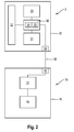
- Fig. 2 shows the essential components of the laser receiver 3 and the height adjustment 16, which regulate the height adjustment of the tripod 2, schematically in the form of a block diagram.
- the laser receiver 3 comprises a housing 30 into which an operating device 31, a detector device 32 for detecting the laser beam 28 and a display device 33 are integrated.
- the detector device 32 and the display device 33 are connected to an evaluation device 34 , which determines the difference between the actual position 26 and the desired position 27.
- the evaluation device 34 is connected to a control device 35 for controlling the laser receiver 3, wherein the evaluation and control devices 34, 35 are integrated into a microcontroller 36 .
- the height adjustment device 16 of the stand 2 comprises the drive unit 19 and a control device 37 in the form of a microcontroller for controlling the height adjustment device 16.
- the communication between the laser receiver 3 and the height adjustment device 16 via a wireless communication link 38, the first transmitting / receiving unit 39 in Laser receiver 3 with a second transmitting / receiving unit 40 in the height adjustment device 16 connects.
- a reference mark is deposited in the microcontroller 36 of the laser receiver 3.
- the desired position 27, in which the stand 2 is to be arranged may be the reference mark.
- the target position 27 can be entered as an offset to the reference mark by the operator in the form of a numerical value via the operating devices 31.
- Fig. 3 shows a method for height adjustment of the tripod 2 with the aid of the device according to the invention 1.
- the tripod 2 is for example designed so that the rack 14 when switching off or at the latest when switching the tripod 2 is moved to the lower end position.
- the operator adjusts the length and the standing position of the tripod legs 7 so that the laser beam 28 is arranged in the lower end position of the rack 14 in the region of the laser receiver 3 below the detector device 32.
- a step S1 the operator starts the laser receiver 3 and the laser device 5, which emits the laser beam 28.
- a step S2 it is checked whether the laser beam 28 has hit the detector device 32. If the laser beam 28 has hit the detector device 32 (J in S2), a corresponding signal is transmitted from the detector device 32 to the microcontroller 36 of the laser receiver 3 in a step S3 .
- the microcontroller 36 calculates the difference of the actual position 26 to the desired position 27 in the height direction 15 in a step S4 and transmits in a step S5 a control signal corresponding to the difference via the communication link 38 and the transmitting / receiving units 39, 40 to the control device 37 of the stand 2.
- the controller 37 issues in a step S6 in accordance with the control signal, a command to the drive unit 19, the rack 14 in a step S7 in the height direction 15 by the difference in the desired position 27 moves.
- the control device 37 transmits a signal to the microcontroller 36 of the laser receiver 3 that the height adjustment of the stand 2 has ended.
- the height adjustment of the tripod 2 can be terminated at this point or the accuracy of the height adjustment can be checked in a control loop.
- the control loop is in Fig. 3 shown in dashed lines.
- a signal corresponding to the current actual position 26 of the laser beam 28 is transmitted from the detector device 32 to the microcontroller 36.
- the difference of the actual position 26 is calculated to the desired position 27 and tested in step S11 , whether an allowable deviation is not exceeded. If the difference is larger than the allowable deviation (N in S11), the process proceeds to step S5. If the difference is smaller than the allowable deviation (J in S11), the end of the height adjustment is displayed on the display device 33 in a step S12 .
- the method for adjusting the height of the tripod 2 is completed after step S12.
- step S12 If the control loop of steps S9 to S11 for checking the accuracy of the height adjustment is not performed, the process for height adjustment of the stand 2 after step S8 is completed with the display on the display 33 that the height adjustment is completed (step S12).
- the microcontroller 36 of the laser receiver 3 transmits a corresponding signal to the control device 37 of the height adjustment device 16 of the stand 2 in a step S13 .
- the control device 37 issues in a step S14 a command to the drive unit 19, which moves the rack 14 in a step S15 upwards.
- "top” means that the rack 14 is moved away from the base 11, on which the stand 2 is placed, in the height direction 15.
- a step S16 it is checked whether the laser beam 28 has hit the detector device 32. If the laser beam 28 has hit the detector device 32 (J in S16), the process proceeds to step S3. If the laser beam 28 has not hit the detector device 32 (N in S16), the method of adjusting the height of the tripod 2 is continued with step S13.
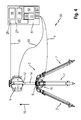
- Fig. 4 shows a second embodiment an inventive device 50 for height adjustment of the stand 2 with a laser receiver 51 which is connected via the communication link 4 with the height adjusting means sixteenth
- the laser receiver 51 differs from the laser receiver 3 of Fig. 2 in that, in addition to the components 31, 32, 33, 36, a remote control device 52 for operating the laser device 5 in the laser receiver 51 is provided.
- the laser receiver 51 is connected to the laser device 5 via a further communication connection 53 .
- the communication links 4, 53 are connected to the first transmitting / receiving unit 39 in the laser receiver 51.
- the communication links 4, 53 may be connected to the laser receiver 51 via various transceiver units.
- the transmitting / receiving unit 39 is connected to a switching device 54 which can activate or deactivate the communication links 4, 53 between the laser receiver 51 and the height adjusting device 16 and between the laser receiver 51 and the laser device 5.
- the laser receiver 51 is switchable via a mode switch 55 between a first operating mode, a second operating mode and a third operating mode.
- the laser receiver 51 serves as in FIG Fig. 3 described for height adjustment, in the second operating mode for optical and / or acoustic display of a laser beam and in the third operating mode for remote control of the laser device. 5
- the laser receiver 51 is a part of the inventive device 50 for height adjustment of the tripod 2.
- the communication link 4 between the laser receiver 51 and the height adjuster 16 is activated and the microcontroller 36 of the laser receiver 51 created to control thetexneinstell responded 16 one of the difference between the Actual position 26 and the target position 27 corresponding control signal which is transmitted via the active communication link 4 to the height adjustment device 16.
- the difference is transmitted via the active communication link 4 to the microcontroller 37 of the height adjustment device 16 and the microcontroller 37 generates a corresponding control signal for controlling the drive unit 19.
- the method for height adjustment can be further automated.
- the communication links 4, 53 between the laser receiver 51 and the height adjuster 16 and between the laser receiver 51 and the laser device 5 are activated.
- the microcontroller 36 transmits a control signal to the laser device 5 to deactivate the shock function of the laser device 5 and to emit the laser beam 28.
- the microcontroller 36 communicates via the communication link 53 directly with the laser device 5 and controls the laser device 5 accordingly.
- the height adjustment can be carried out fully automatically with the device 50, the operator only has to set the first operating mode.
- the laser receiver 51 is switched from the first operating mode to the second operating mode after the end of the automatic height adjustment.
- In the second mode of operation of the laser receiver 51 operates as a display device for optical and / or acoustic display of the laser beam 28.
- the communication links 4, 53 between the laser receiver 51 and the height adjuster 16 and between the laser receiver 51 and the laser device 5 are deactivated.
- the laser receiver 51 displays the laser beam 28 and the difference of the actual position 26 to the desired position 27 on the display device 33 optically and / or acoustically.
- the laser receiver 51 is used for remote control of the laser device 5.
- the communication link 4 between the laser receiver 51 and the height adjuster 16 is deactivated and the communication link 53 between the laser receiver 3 and the laser device 5 is activated.
- the inputs to the remote control device 52 of the laser receiver 51 are transmitted to the laser device 5 via the communication link 53.
Landscapes
- Physics & Mathematics (AREA)
- Engineering & Computer Science (AREA)
- General Physics & Mathematics (AREA)
- Radar, Positioning & Navigation (AREA)
- Remote Sensing (AREA)
- Conveying And Assembling Of Building Elements In Situ (AREA)
- Length Measuring Devices By Optical Means (AREA)
- Optical Radar Systems And Details Thereof (AREA)
- Optical Communication System (AREA)
Applications Claiming Priority (2)
| Application Number | Priority Date | Filing Date | Title |
|---|---|---|---|
| DE201010030593 DE102010030593A1 (de) | 2010-06-28 | 2010-06-28 | Vorrichtung und Verfahren zur Höheneinstellung eines Ständers |
| EP11167201.0A EP2400263B1 (fr) | 2010-06-28 | 2011-05-24 | Procédé destinés au réglage en hauteur d'un support |
Related Parent Applications (2)
| Application Number | Title | Priority Date | Filing Date |
|---|---|---|---|
| EP11167201.0A Division EP2400263B1 (fr) | 2010-06-28 | 2011-05-24 | Procédé destinés au réglage en hauteur d'un support |
| EP11167201.0A Division-Into EP2400263B1 (fr) | 2010-06-28 | 2011-05-24 | Procédé destinés au réglage en hauteur d'un support |
Publications (1)
| Publication Number | Publication Date |
|---|---|
| EP2966403A1 true EP2966403A1 (fr) | 2016-01-13 |
Family
ID=44675426
Family Applications (2)
| Application Number | Title | Priority Date | Filing Date |
|---|---|---|---|
| EP11167201.0A Active EP2400263B1 (fr) | 2010-06-28 | 2011-05-24 | Procédé destinés au réglage en hauteur d'un support |
| EP15177262.1A Withdrawn EP2966403A1 (fr) | 2010-06-28 | 2011-05-24 | Dispositif destine au reglage en hauteur d'un support |
Family Applications Before (1)
| Application Number | Title | Priority Date | Filing Date |
|---|---|---|---|
| EP11167201.0A Active EP2400263B1 (fr) | 2010-06-28 | 2011-05-24 | Procédé destinés au réglage en hauteur d'un support |
Country Status (3)
| Country | Link |
|---|---|
| EP (2) | EP2400263B1 (fr) |
| CN (1) | CN102297325A (fr) |
| DE (1) | DE102010030593A1 (fr) |
Families Citing this family (15)
| Publication number | Priority date | Publication date | Assignee | Title |
|---|---|---|---|---|
| NL1039289C2 (nl) * | 2012-01-12 | 2013-07-15 | Iihan Icoz | Werkwijze voor het stellen van een laser alsmede een statief. |
| CN102735211A (zh) * | 2012-07-04 | 2012-10-17 | 江苏省华建建设股份有限公司 | 单人可操作式全天候水准仪 |
| CN102798377B (zh) * | 2012-08-07 | 2014-07-09 | 张东光 | 平面误差测量分析系统及方法 |
| CN104006838A (zh) * | 2013-02-27 | 2014-08-27 | 苏州工业园区欧霸动力设备有限公司 | 通用测量仪器架子 |
| EP2998699B1 (fr) * | 2014-09-18 | 2019-02-20 | MOBA Mobile Automation AG | Procédé de traitement d'une référence de hauteur pour un outil d'un engin, dispositif et procédé de réglage en hauteur d'un outil d'un engin, engin |
| EP3237840B1 (fr) * | 2014-12-24 | 2020-05-20 | Robert Bosch GmbH | Procédé pour le positionnement d'un faisceau laser tournant à l'aide d'un récepteur laser |
| CN107701887B (zh) * | 2017-10-17 | 2023-09-01 | 广东电网有限责任公司清远供电局 | 一种可自动保持高度的伸缩重载杆及高度保持方法 |
| CN108468935A (zh) * | 2018-05-05 | 2018-08-31 | 武汉京天鼎承科技有限公司 | Td-lte射频处理单元挂墙连接装置 |
| CN109141834A (zh) * | 2018-10-30 | 2019-01-04 | 深圳市杰普特光电股份有限公司 | 激光检测装置及激光检测控制方法 |
| US11320263B2 (en) | 2019-01-25 | 2022-05-03 | Stanley Black & Decker Inc. | Laser level system |
| JP7287820B2 (ja) * | 2019-04-02 | 2023-06-06 | 株式会社トプコン | 測量装置 |
| CN110212994A (zh) * | 2019-06-25 | 2019-09-06 | 上海剀蕊得信息科技有限公司 | 一种无线通信设备的检测装置 |
| CN110658512B (zh) * | 2019-11-08 | 2022-11-18 | 深圳职业技术学院 | 能全自动收纳及调整三角支架高度的激光测距仪装置 |
| CN114964149A (zh) * | 2022-05-20 | 2022-08-30 | 北京市测绘设计研究院 | 超高层标高引测系统 |
| CN119460207B (zh) * | 2025-01-15 | 2025-04-08 | 长春国地探测仪器工程技术股份有限公司 | 一种地空探测信号接收设备安装支架 |
Citations (8)
| Publication number | Priority date | Publication date | Assignee | Title |
|---|---|---|---|---|
| US5903345A (en) * | 1996-03-01 | 1999-05-11 | Dwbh Ventures Ltd. | Remotely positionable gravity oriented laser scanner |
| US20020017028A1 (en) * | 1999-12-16 | 2002-02-14 | Wishart James Scott | Apparatus for and a method of providing a reference point or line |
| DE20200218U1 (de) | 2001-01-08 | 2002-04-04 | Mayer & Wonisch GmbH & Co. KG, 59757 Arnsberg | Mess-System |
| US6369755B1 (en) * | 1995-10-23 | 2002-04-09 | Trimble Navigation Limited | Integrated SATPS total survey station |
| EP1203930A2 (fr) * | 2000-11-03 | 2002-05-08 | Nestle & Fischer GmbH & Co. KG | Procédé et dispositif pour aligner un rayon de lumière généré par un laser à rotation |
| US7152334B2 (en) | 2004-11-22 | 2006-12-26 | Agatec | Controlled support frame to position a laser level |
| DE102008001619A1 (de) * | 2008-05-07 | 2009-11-12 | Robert Bosch Gmbh | Mobiles Messsystem und Messverfahren |
| US20100157283A1 (en) * | 2008-12-19 | 2010-06-24 | Trimble Navigation Limited | Laser slope adjustment |
Family Cites Families (3)
| Publication number | Priority date | Publication date | Assignee | Title |
|---|---|---|---|---|
| DE19952390A1 (de) * | 1999-10-29 | 2001-05-03 | Hilti Ag | Rotationsbaulaser |
| CN101114531A (zh) * | 2007-07-23 | 2008-01-30 | 金连河 | 三角架自动对中置平系统 |
| CN201504402U (zh) * | 2009-08-18 | 2010-06-16 | 陈浩 | 一种全自动激光控制平地系统 |
-
2010
- 2010-06-28 DE DE201010030593 patent/DE102010030593A1/de not_active Withdrawn
-
2011
- 2011-05-24 EP EP11167201.0A patent/EP2400263B1/fr active Active
- 2011-05-24 EP EP15177262.1A patent/EP2966403A1/fr not_active Withdrawn
- 2011-06-23 CN CN2011101698981A patent/CN102297325A/zh active Pending
Patent Citations (8)
| Publication number | Priority date | Publication date | Assignee | Title |
|---|---|---|---|---|
| US6369755B1 (en) * | 1995-10-23 | 2002-04-09 | Trimble Navigation Limited | Integrated SATPS total survey station |
| US5903345A (en) * | 1996-03-01 | 1999-05-11 | Dwbh Ventures Ltd. | Remotely positionable gravity oriented laser scanner |
| US20020017028A1 (en) * | 1999-12-16 | 2002-02-14 | Wishart James Scott | Apparatus for and a method of providing a reference point or line |
| EP1203930A2 (fr) * | 2000-11-03 | 2002-05-08 | Nestle & Fischer GmbH & Co. KG | Procédé et dispositif pour aligner un rayon de lumière généré par un laser à rotation |
| DE20200218U1 (de) | 2001-01-08 | 2002-04-04 | Mayer & Wonisch GmbH & Co. KG, 59757 Arnsberg | Mess-System |
| US7152334B2 (en) | 2004-11-22 | 2006-12-26 | Agatec | Controlled support frame to position a laser level |
| DE102008001619A1 (de) * | 2008-05-07 | 2009-11-12 | Robert Bosch Gmbh | Mobiles Messsystem und Messverfahren |
| US20100157283A1 (en) * | 2008-12-19 | 2010-06-24 | Trimble Navigation Limited | Laser slope adjustment |
Also Published As
| Publication number | Publication date |
|---|---|
| EP2400263A3 (fr) | 2012-10-03 |
| CN102297325A (zh) | 2011-12-28 |
| DE102010030593A1 (de) | 2011-12-29 |
| EP2400263A2 (fr) | 2011-12-28 |
| EP2400263B1 (fr) | 2016-01-06 |
Similar Documents
| Publication | Publication Date | Title |
|---|---|---|
| EP2400263B1 (fr) | Procédé destinés au réglage en hauteur d'un support | |
| EP2400204B1 (fr) | Statif doté d'un réglage en hauteur automatique | |
| EP3384236B1 (fr) | Procédé de contrôle et/ou d'étalonnage d'un axe vertical d'un laser rotatif | |
| EP3384239B1 (fr) | Procede de controle et/ou d'etalonnage d'un axe horizontal d'un laser rotatif | |
| DE102012011518B3 (de) | Geodätisches ziel und positionsbestimmungssystem | |
| DE112005003494B4 (de) | Verfahren und Vorrichtung zur Steuerung eines Maschinenelements | |
| EP3028063B1 (fr) | Procédé pour calibrer un appareil de mesure | |
| EP2461132A1 (fr) | Télescope pour l'utilisation dans un instrument de mesure et procédé de collimation automatique automatisée d'un télescope d'un instrument de mesure ayant un objectif de collimation automatique | |
| EP1982247A1 (fr) | Unité de commande d'application | |
| DE102010061725A1 (de) | Rotationslasergerät mit einer geneigten Laserebene und Verfahren zur Ausrichtung eines Rotationslasergerätes | |
| EP3674658A1 (fr) | Procédé de vérification et/ou d'étalonnage d'un axe horizontal d'un laser rotatif | |
| EP2997328B1 (fr) | Dispositif de nivellement de remblais et de matériaux de construction | |
| DE202010006391U1 (de) | Winkelmessvorrichtung für Abkantpressen | |
| EP2936054A1 (fr) | Procédé et dispositif pour déterminer les coordonnées de lieu bidimensionnelles d'un objet cible | |
| EP1939586A2 (fr) | Dispositif de projection laser | |
| DE10161651B4 (de) | Verfahren und Anordnung zum Einbringen von Pfosten für Leitplankensysteme in den Boden | |
| EP1916500A2 (fr) | Procédé et dispositif destinés à la projection d'une ligne de laser de travail horizontale | |
| CN221465772U (zh) | 同步观测跟踪装置 | |
| WO2001046645A1 (fr) | Procede et dispositif pour l'alignement de corps | |
| DE29914297U1 (de) | Laserstrahl-Nivelliergerät | |
| EP1639809A1 (fr) | Systeme a tete pivotante, en particulier pour camera a film et camera video | |
| DE10150089C1 (de) | Schwenklöffel | |
| AT414043B (de) | Vorrichtung zum kuppeln eines selbstregistrierenden elektrooptischen zusatz-messgerätes mit einer selbstregistrierenden elektrooptischen totalstation | |
| DE212025000039U1 (de) | Elektrisch betriebenes Hubstativ und Messsystem, die auf automatische Laserverfolgung anwendbar sind | |
| EP4655139A1 (fr) | Procédé pour commander un robot de construction et robot de construction |
Legal Events
| Date | Code | Title | Description |
|---|---|---|---|
| PUAI | Public reference made under article 153(3) epc to a published international application that has entered the european phase |
Free format text: ORIGINAL CODE: 0009012 |
|
| AC | Divisional application: reference to earlier application |
Ref document number: 2400263 Country of ref document: EP Kind code of ref document: P |
|
| AK | Designated contracting states |
Kind code of ref document: A1 Designated state(s): AL AT BE BG CH CY CZ DE DK EE ES FI FR GB GR HR HU IE IS IT LI LT LU LV MC MK MT NL NO PL PT RO RS SE SI SK SM TR |
|
| RIN1 | Information on inventor provided before grant (corrected) |
Inventor name: JOHN, ANDREAS Inventor name: WINTER, ANDREAS Inventor name: AMMANN, MANFRED Inventor name: EMBERGER, HOLGER-MAX Inventor name: LUKIC, SASHA |
|
| 17P | Request for examination filed |
Effective date: 20160713 |
|
| RBV | Designated contracting states (corrected) |
Designated state(s): AL AT BE BG CH CY CZ DE DK EE ES FI FR GB GR HR HU IE IS IT LI LT LU LV MC MK MT NL NO PL PT RO RS SE SI SK SM TR |
|
| 17Q | First examination report despatched |
Effective date: 20171204 |
|
| STAA | Information on the status of an ep patent application or granted ep patent |
Free format text: STATUS: THE APPLICATION IS DEEMED TO BE WITHDRAWN |
|
| 18D | Application deemed to be withdrawn |
Effective date: 20180615 |