EP2966451A2 - Methode de detection et capteur - Google Patents
Methode de detection et capteur Download PDFInfo
- Publication number
- EP2966451A2 EP2966451A2 EP15175929.7A EP15175929A EP2966451A2 EP 2966451 A2 EP2966451 A2 EP 2966451A2 EP 15175929 A EP15175929 A EP 15175929A EP 2966451 A2 EP2966451 A2 EP 2966451A2
- Authority
- EP
- European Patent Office
- Prior art keywords
- radiation
- diaphragm element
- light
- force
- electrical
- Prior art date
- Legal status (The legal status is an assumption and is not a legal conclusion. Google has not performed a legal analysis and makes no representation as to the accuracy of the status listed.)
- Withdrawn
Links
Images
Classifications
-
- G—PHYSICS
- G01—MEASURING; TESTING
- G01R—MEASURING ELECTRIC VARIABLES; MEASURING MAGNETIC VARIABLES
- G01R33/00—Arrangements or instruments for measuring magnetic variables
- G01R33/02—Measuring direction or magnitude of magnetic fields or magnetic flux
- G01R33/028—Electrodynamic magnetometers
- G01R33/0283—Electrodynamic magnetometers in which a current or voltage is generated due to relative movement of conductor and magnetic field
-
- G—PHYSICS
- G01—MEASURING; TESTING
- G01D—MEASURING NOT SPECIALLY ADAPTED FOR A SPECIFIC VARIABLE; ARRANGEMENTS FOR MEASURING TWO OR MORE VARIABLES NOT COVERED IN A SINGLE OTHER SUBCLASS; TARIFF METERING APPARATUS; MEASURING OR TESTING NOT OTHERWISE PROVIDED FOR
- G01D5/00—Mechanical means for transferring the output of a sensing member; Means for converting the output of a sensing member to another variable where the form or nature of the sensing member does not constrain the means for converting; Transducers not specially adapted for a specific variable
- G01D5/26—Mechanical means for transferring the output of a sensing member; Means for converting the output of a sensing member to another variable where the form or nature of the sensing member does not constrain the means for converting; Transducers not specially adapted for a specific variable characterised by optical transfer means, i.e. using infrared, visible, or ultraviolet light
- G01D5/32—Mechanical means for transferring the output of a sensing member; Means for converting the output of a sensing member to another variable where the form or nature of the sensing member does not constrain the means for converting; Transducers not specially adapted for a specific variable characterised by optical transfer means, i.e. using infrared, visible, or ultraviolet light with attenuation or whole or partial obturation of beams of light
- G01D5/34—Mechanical means for transferring the output of a sensing member; Means for converting the output of a sensing member to another variable where the form or nature of the sensing member does not constrain the means for converting; Transducers not specially adapted for a specific variable characterised by optical transfer means, i.e. using infrared, visible, or ultraviolet light with attenuation or whole or partial obturation of beams of light the beams of light being detected by photocells
-
- G—PHYSICS
- G01—MEASURING; TESTING
- G01K—MEASURING TEMPERATURE; MEASURING QUANTITY OF HEAT; THERMALLY-SENSITIVE ELEMENTS NOT OTHERWISE PROVIDED FOR
- G01K5/00—Measuring temperature based on the expansion or contraction of a material
- G01K5/48—Measuring temperature based on the expansion or contraction of a material the material being a solid
- G01K5/56—Measuring temperature based on the expansion or contraction of a material the material being a solid constrained so that expansion or contraction causes a deformation of the solid
- G01K5/62—Measuring temperature based on the expansion or contraction of a material the material being a solid constrained so that expansion or contraction causes a deformation of the solid the solid body being formed of compounded strips or plates, e.g. bimetallic strip
- G01K5/70—Measuring temperature based on the expansion or contraction of a material the material being a solid constrained so that expansion or contraction causes a deformation of the solid the solid body being formed of compounded strips or plates, e.g. bimetallic strip specially adapted for indicating or recording
-
- G—PHYSICS
- G01—MEASURING; TESTING
- G01L—MEASURING FORCE, STRESS, TORQUE, WORK, MECHANICAL POWER, MECHANICAL EFFICIENCY, OR FLUID PRESSURE
- G01L1/00—Measuring force or stress, in general
- G01L1/25—Measuring force or stress, in general using wave or particle radiation, e.g. X-rays, microwaves, neutrons
-
- G—PHYSICS
- G01—MEASURING; TESTING
- G01P—MEASURING LINEAR OR ANGULAR SPEED, ACCELERATION, DECELERATION, OR SHOCK; INDICATING PRESENCE, ABSENCE, OR DIRECTION, OF MOVEMENT
- G01P15/00—Measuring acceleration; Measuring deceleration; Measuring shock, i.e. sudden change of acceleration
- G01P15/02—Measuring acceleration; Measuring deceleration; Measuring shock, i.e. sudden change of acceleration by making use of inertia forces using solid seismic masses
- G01P15/08—Measuring acceleration; Measuring deceleration; Measuring shock, i.e. sudden change of acceleration by making use of inertia forces using solid seismic masses with conversion into electric or magnetic values
- G01P15/093—Measuring acceleration; Measuring deceleration; Measuring shock, i.e. sudden change of acceleration by making use of inertia forces using solid seismic masses with conversion into electric or magnetic values by photoelectric pick-up
-
- G—PHYSICS
- G01—MEASURING; TESTING
- G01R—MEASURING ELECTRIC VARIABLES; MEASURING MAGNETIC VARIABLES
- G01R15/00—Details of measuring arrangements of the types provided for in groups G01R17/00 - G01R29/00, G01R33/00 - G01R33/26 or G01R35/00
- G01R15/14—Adaptations providing voltage or current isolation, e.g. for high-voltage or high-current networks
- G01R15/24—Adaptations providing voltage or current isolation, e.g. for high-voltage or high-current networks using light-modulating devices
-
- G—PHYSICS
- G01—MEASURING; TESTING
- G01R—MEASURING ELECTRIC VARIABLES; MEASURING MAGNETIC VARIABLES
- G01R33/00—Arrangements or instruments for measuring magnetic variables
- G01R33/02—Measuring direction or magnitude of magnetic fields or magnetic flux
- G01R33/032—Measuring direction or magnitude of magnetic fields or magnetic flux using magneto-optic devices, e.g. Faraday or Cotton-Mouton effect
-
- G—PHYSICS
- G01—MEASURING; TESTING
- G01R—MEASURING ELECTRIC VARIABLES; MEASURING MAGNETIC VARIABLES
- G01R33/00—Arrangements or instruments for measuring magnetic variables
- G01R33/02—Measuring direction or magnitude of magnetic fields or magnetic flux
- G01R33/038—Measuring direction or magnitude of magnetic fields or magnetic flux using permanent magnets, e.g. balances, torsion devices
- G01R33/0385—Measuring direction or magnitude of magnetic fields or magnetic flux using permanent magnets, e.g. balances, torsion devices in relation with magnetic force measurements
-
- G—PHYSICS
- G01—MEASURING; TESTING
- G01R—MEASURING ELECTRIC VARIABLES; MEASURING MAGNETIC VARIABLES
- G01R15/00—Details of measuring arrangements of the types provided for in groups G01R17/00 - G01R29/00, G01R33/00 - G01R33/26 or G01R35/00
- G01R15/14—Adaptations providing voltage or current isolation, e.g. for high-voltage or high-current networks
- G01R15/22—Adaptations providing voltage or current isolation, e.g. for high-voltage or high-current networks using light-emitting devices, e.g. LED, optocouplers
Definitions
- the present invention relates to a metrological method for detecting, converting and manipulating motion-causing, force or torque-based and optical input signals in either amplitude-modulated light signals or comparable amplitude-modulated electromagnetic radiation signals and for further conversion thereof into electrical signals.
- the present invention relates to transducers for carrying out the method.
- the transducer is a micromechanical assembly, i. the movements are limited to very small distances, preferably less than 1 mm, for example 10 ⁇ m, or very small angle changes, preferably by an angular range of less than 30 °.
- the transducer modifies optical signals by optomechanically modulating electromagnetic radiation paths.
- such a transducer can also be referred to as a micro-optomechanical sensor.
- Electrically controlled light sources in particular light-emitting diodes: these can convert electrical input variables into light of a specific spectral range, as a result of which electrical signals can also be transmitted via light waves to other locations (via free space, waveguides or via light guides, such as glass fibers). Infrared diodes are also mentioned here.
- Photodiodes, phototransistors, photovoltaic elements, radiation detectors and the like allow the conversion of light or certain electromagnetic waves into electrical signals (current / voltage).
- Light modulators these modulate polarized light using optically active substances (liquid crystals). This can be amplified or even phase-modulated by an electrical signal, depending on the design of a light beam. Here, the alignment of the liquid crystals by an electrical voltage for the modulation effect.
- Optocouplers these devices convert electrical input quantities into light intensities by driving an electrically operated light source and the light signal by means of photodiodes or phototransistors back into electrical output variables. Optocouplers serve the electrical isolation of electrical signals.
- Optical absolute encoders these output a unique digital code for each positioning position or each angular position to be detected, which is represented by a binary line pattern through a plurality of miniaturized light barriers.
- An example is in US 4,385,234 shown where a coding disc with a drive axis relative to an optics with a light source and a sensor matrix is rotatably mounted in a housing.
- this device usually designed as an iris diaphragm, allows the mechanical change of the opening of a light passage on lenses of photographic equipment or film cameras.
- a special diaphragm shape for use as a variable optical damper is shown in FIG US 6,404,970 wherein a plurality of openings in a component is regularly arranged. In this case, the opening diameter of the openings in an expansion direction of the component increases steadily, whereby the component has a position-dependent light transmission.
- Another integrated variable optical damper is in FR 2 839 060 published, wherein a comb drive a deflection mirror in response to the applied voltage in a Introduces light passage, whereby a portion of the amount of light in the light passage is deflected out of the light channel.
- vibration sensor formed by a hybrid opto-micro-electro-mechanical system is published.
- An illustration shows a rectangular diaphragm element movably mounted on meandering springs. This is made of a silicon structure from an SOI (silicon-on-insulator) wafer and has square etched openings.
- comb structures are attached to the longitudinal sides, the function of which is not explained in detail in this publication.
- the invention is now intended to remedy the aforementioned disadvantages of the prior art and allow additional functions. Therefore, a method has been sought which, in addition to already described and known applications and transfer functions, enables potential-isolated, isolated measurement of an input variable defined by the device from a set of now different possible input variables.
- Possible transfer functions are to be determinable by a precalculation of the effect of the shape of the position or angular position-dependent sectional area of a suitably selected light projection with the location-dependent suitably selected light transmission.
- the device for carrying out the method should have very specially selected cross-sectional shape designs of the light apertures in the movably mounted aperture element, as well as paired, specially selected shapes or patterns for the light projection.
- the position or rotational position of the measuring mass should be optically detectable by the measuring mass is also effective as part of a mechanical light modulation system, which transmits more or less light depending on the relative position of its components.
- At least one transfer function is formed by the shaping of the components of the mechanical light modulation system or the modulation system for the electromagnetic waves, in such a way that at least one useful signal manipulation takes place via the path or angular position of the measuring mass detection.
- the signal manipulation can, for example, have the task of compensating the non-linearities of input variables and of distance- or angle-dependent opposing forces, or deliberately consciously incorporating particular nonlinearities piecewise, for example different slopes depending on the distance or angle section of the movement space (eg for different intensity measurement ranges).
- Measuring instruments require a robust, reliable and as accurate as possible conversion of an input variable into an output variable.
- the detected signals must be adapted to the measuring system. If the signals are out of range, matching devices are needed. If the signals are too small, they must be amplified, but noise (noise) should be suppressed. If the signals are too large they must first be attenuated. Certain signals behave exponentially, others are e.g. logarithmically perceived (e.g., volume, brightness), which is why the logarithm of the measurand should be appropriately measured and controlled. Some signals are filtered, some are linearized, some are digitized for further processing.
- signal manipulations by suitable designs can achieve modulation (a certain input signal frequency multiplication, eg doubling, tripling), signal full wave or half wave rectification, or dynamic effects known from acoustic manipulation individually, in parallel or in combination, for example that of a compressor, a limiter , or from an enhancer, an expander, or a noise gate.
- Digital signal transformations should be able to be output in parallel.
- At least one path-dependent opposing force should be provided, which compensates for the force to be measured as of a certain deflection of the measuring mass from an initial or rest position.
- a complete electrical decoupling should result. This is of particular importance when the light signal is converted back to electrical but manipulated signals via photoelectric converters.
- the method allows short development times or adaptations of signal transducers with special transmission characteristics.
- the formation of the specifically desired transfer characteristic does not require any electronic components, since the signal manipulation can take place in a dazzling optical way.
- several transmission functions can be formed in parallel in one component and output through several outputs.
- Various transmission characteristics can be summed up by parallel arrangement.
- the output signal of the converter can be fed via optical fibers or waveguides of an evaluation.
- the measured input variables are used directly for the modulation of a light path or the modulation of the transmission path of the electromagnetic wave.
- the light or electromagnetic wave source may or may not be attached to the transducer. It is also possible to supply light guides with light or special guides for the electromagnetic waves to guide these waves to the transducer. In principle, natural lighting (daylight) or artificial room lighting of the environment can also serve as the light source.
- the light source can be modulated. This allows cross modulation and multiplication functions. Several light or wave sources can be used in parallel, even with different spectral components for different zones.
- the object is achieved by a novel method for optomechanical detection and conversion of an input signal to be measured.
- This input signal can be a mechanical, an electrostatic, a magnetic or an electrodynamic variable, which then influences an electromagnetic radiation channel via the intermediate step by conversion into a path signal.
- an input signal dependent electromagnetic output signal e.g. generates a specific luminous flux.
- This can be converted as a result of again via a radiation-sensitive sensor, for example, a photosensor in an electrical signal. This is, for example, a dependent on the input signal electrical DC or AC voltage or a DC or AC.
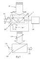
- an opto-mechanical transfer function is formed, wherein radiation components of an electromagnetic radiation projection, for example of a light projection, are transmitted or shadowed by a special component as a function of its position or its angular position.
- the electromagnetic signals used for this purpose preferably have wavelengths in the range of 100 nm to 10 ⁇ m and are limited in the possible spatial expansion directions. Visible rays of this electromagnetic Radiation projection would show on a plane projection surface a previously defined pattern with at least one outer contour and possibly also unirradiated or shaded areas within the contour. But also for non-visible electromagnetic radiation there are defined impact zones and zones where no radiation is supplied.
- this geometric shape and / or pattern predetermined projection is partly due to a thin flat areal and preferably opaque aperture element and partly by at least one radiation passage at this aperture element, which is aligned frontally against the source of the radiation projection.
- the beam transmission on the diaphragm element has a geometrically predetermined and preferably etched cross-sectional surface shape.
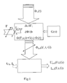
- the optically or photo- or radiation-sensor-detectable output signal for the given relative spatial position (x, y) or relative orientation position ( ⁇ ) is converted into a path or angle of a dependent transmission flow. How much light or radiation penetrates through the specially shaped apertures / radiation passages in the observed frequency spectrum is given by the intersection (or mathematical convolution) of the projected geometric shapes and patterns and the radiation passage cross-sectional areas depending on position or angle. Since more than one sensor can be arranged opposite the light or radiation exit sides of a plurality of radiation passages, a plurality of signals can also be formed from the respective intersections.
- this method according to the invention is suitable for input signals which are based on gravitational force, inertial force, mass moment of inertia or centrifugal force, these forces acting on the mass of the diaphragm element accelerating.
- the device for carrying out the method is the subject of the invention.
- Alternative drive devices for the diaphragm element are preferably mechanical levers (also piezo elements, thermal length changes, bimetallic strip), gear rack pairing, magnets, magnetic materials, coils, electric motor drives.
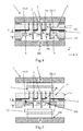
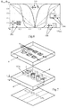
- Fig. 7 For example, the typical structure is shown with the quiescent optical shutter 6, the movable shutter 300 and the quiescent flux (detector) surface.
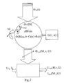
- a torque-counter-torque pairing for torque-angle conversion may represent an alternative application of the inventive method.
- This is functional in the block diagram Fig. 2 shown.
- the output radiation flux ⁇ out determining variables are then the measured moment M, using the compensation moment M Comp , the angle ⁇ and the modulation of the input radiation flux ⁇ in over time and the shape geometry of the aperture light projection pairing in dependence on the relative rotation angle ⁇ , ⁇ reflects the variable relative position of the radiation projection with respect to the position of the movable diaphragm element and defines itself in a polar coordinate system normal to the main plane of extent of the movable diaphragm by the given r and ⁇ coordinates in a defined range of values (r min ..r .. .r max , ⁇ min ... ⁇ ... ⁇ max ).
- a transfer function G is uniquely described.
- one or more signals can also be manipulated via the iris optical transmission function (s) 100 according to predetermined criteria.
- An example would be an exponential light filter.
- vibrations or movement or torsion signals can be manipulated selectively and form a wide variety of electrical output signals.
- electrostatic drive CombDrive
- electrical signals can be converted directly into amplitudes of the luminous flux or the radiant flux and into electrical signals again via the radiation-sensitive sensor. For this, only a very few different components are required, but a multiplicity of functions can also be formed in parallel. Beyond a common optocoupler functions can be integrated into the optics, which would otherwise be possible only by considerable effort in an electronic circuit.
- FIG. 6 the output signal (normalized representation) is shown for four different apertures (stationary) and apertures (moved to).
- the dashed graph in Fig. 6 shows a linear course corresponding to a pair of square apertures with square apertures corresponding to the rearmost portion Fig. 7 ,
- the aperture is cross-shaped as in the subsequent section in Fig. 7 , so gets the linear course (see thin line in Fig. 6 ) According to the opening width in the direction of movement two different slopes, in the longitudinal beam portion of the cross, the slope is shallower than in the crossbar section.
Landscapes
- Physics & Mathematics (AREA)
- General Physics & Mathematics (AREA)
- Condensed Matter Physics & Semiconductors (AREA)
- Health & Medical Sciences (AREA)
- Toxicology (AREA)
- Engineering & Computer Science (AREA)
- Power Engineering (AREA)
- Mechanical Light Control Or Optical Switches (AREA)
- Measuring Fluid Pressure (AREA)
Applications Claiming Priority (2)
| Application Number | Priority Date | Filing Date | Title |
|---|---|---|---|
| AT2252011 | 2011-04-18 | ||
| EP12722686.8A EP2702415A2 (fr) | 2011-04-18 | 2012-04-18 | Methode de detection et capteur |
Related Parent Applications (1)
| Application Number | Title | Priority Date | Filing Date |
|---|---|---|---|
| EP12722686.8A Division EP2702415A2 (fr) | 2011-04-18 | 2012-04-18 | Methode de detection et capteur |
Publications (2)
| Publication Number | Publication Date |
|---|---|
| EP2966451A2 true EP2966451A2 (fr) | 2016-01-13 |
| EP2966451A3 EP2966451A3 (fr) | 2016-06-22 |
Family
ID=47041972
Family Applications (2)
| Application Number | Title | Priority Date | Filing Date |
|---|---|---|---|
| EP12722686.8A Withdrawn EP2702415A2 (fr) | 2011-04-18 | 2012-04-18 | Methode de detection et capteur |
| EP15175929.7A Withdrawn EP2966451A3 (fr) | 2011-04-18 | 2012-04-18 | Methode de detection et capteur |
Family Applications Before (1)
| Application Number | Title | Priority Date | Filing Date |
|---|---|---|---|
| EP12722686.8A Withdrawn EP2702415A2 (fr) | 2011-04-18 | 2012-04-18 | Methode de detection et capteur |
Country Status (2)
| Country | Link |
|---|---|
| EP (2) | EP2702415A2 (fr) |
| WO (1) | WO2012143408A2 (fr) |
Cited By (1)
| Publication number | Priority date | Publication date | Assignee | Title |
|---|---|---|---|---|
| WO2023155952A1 (fr) * | 2022-02-16 | 2023-08-24 | Ic-Haus Gmbh | Dispositif de détection de position pour codeur optique de position |
Citations (3)
| Publication number | Priority date | Publication date | Assignee | Title |
|---|---|---|---|---|
| US4385234A (en) | 1980-11-25 | 1983-05-24 | Bei Electronics, Inc. | Optical systems for optical encoders |
| US6404970B1 (en) | 2000-05-22 | 2002-06-11 | Jds Uniphase Inc. | Variable optical attenuator |
| FR2839060A3 (fr) | 2002-04-30 | 2003-10-31 | Memscap | Attenuateur optique variable |
Family Cites Families (9)
| Publication number | Priority date | Publication date | Assignee | Title |
|---|---|---|---|---|
| DE971878C (de) * | 1954-02-27 | 1959-04-09 | Licentia Gmbh | Verfahren zur Messung von Strom, Spannung, Leistung oder anderen elektrischen Groessen in Hochspannungsnetzen |
| DE1092813B (de) * | 1958-10-31 | 1960-11-10 | Siemens & Halke Ag | Anordnung zur Messgroessenuebertragung von der Hochspannungsseite auf die Niederspannungsseite |
| US3412324A (en) * | 1966-08-24 | 1968-11-19 | Gen Electric | Optical magnetometer based on the principle of frustrated total internal reflection of light |
| US3731542A (en) * | 1971-03-26 | 1973-05-08 | Honeywell Inc | Optical accelerometer |
| US4720631A (en) * | 1985-12-12 | 1988-01-19 | The Laitram Corporation | Electro-optical compass card wherein transmissive member has random patterns that repeat for particular rotational positions |
| US5936294A (en) * | 1996-05-28 | 1999-08-10 | Motorola, Inc. | Optical semiconductor component and method of fabrication |
| US6568268B1 (en) * | 2001-10-31 | 2003-05-27 | Western Digital Technologies, Inc. | Multi-axis accelerometer comprising a mass suspended by springs above an optical sensor |
| JP2006105764A (ja) * | 2004-10-05 | 2006-04-20 | Matsushita Electric Works Ltd | 加速度センサ |
| US7253616B2 (en) * | 2005-10-13 | 2007-08-07 | Lucent Technologies Inc. | Microelectromechanical magnetometer |
-
2012
- 2012-04-18 EP EP12722686.8A patent/EP2702415A2/fr not_active Withdrawn
- 2012-04-18 WO PCT/EP2012/057098 patent/WO2012143408A2/fr not_active Ceased
- 2012-04-18 EP EP15175929.7A patent/EP2966451A3/fr not_active Withdrawn
Patent Citations (3)
| Publication number | Priority date | Publication date | Assignee | Title |
|---|---|---|---|---|
| US4385234A (en) | 1980-11-25 | 1983-05-24 | Bei Electronics, Inc. | Optical systems for optical encoders |
| US6404970B1 (en) | 2000-05-22 | 2002-06-11 | Jds Uniphase Inc. | Variable optical attenuator |
| FR2839060A3 (fr) | 2002-04-30 | 2003-10-31 | Memscap | Attenuateur optique variable |
Non-Patent Citations (1)
| Title |
|---|
| "ScienceDirect, Procedia Engineering", vol. 5, October 2010, ELSEVIER, pages: 420 - 423 |
Cited By (1)
| Publication number | Priority date | Publication date | Assignee | Title |
|---|---|---|---|---|
| WO2023155952A1 (fr) * | 2022-02-16 | 2023-08-24 | Ic-Haus Gmbh | Dispositif de détection de position pour codeur optique de position |
Also Published As
| Publication number | Publication date |
|---|---|
| WO2012143408A3 (fr) | 2012-12-27 |
| EP2702415A2 (fr) | 2014-03-05 |
| WO2012143408A2 (fr) | 2012-10-26 |
| EP2966451A3 (fr) | 2016-06-22 |
Similar Documents
| Publication | Publication Date | Title |
|---|---|---|
| DE102021201585A1 (de) | Capacitive charge based self-sensing and position observer for electrostatic mems mirrors | |
| DE69823401T2 (de) | Schwingungsfeststellungs- und Steuerungssystem für Drücker | |
| EP3196598B1 (fr) | Dispositif optique de mesure de position | |
| DE102006058805B4 (de) | Vorrichtung zur Eingabe von Bewegungen und/oder Erfassung von Kräften | |
| EP2607918A2 (fr) | Dispositif de mesure d'une distance par rapport à un objet cible | |
| DE102017002862A1 (de) | Winkelmagnetfeldsensor für Scanner | |
| DE102011018684A1 (de) | Aufzeichnungs- und Registrierungsverfahren für ein Versetzungsmeßgerät mit vier Freiheitsgraden für mikrofrequente Boden- und Baukörperversetzungen | |
| EP0363620A1 (fr) | Dispositif photoélectrique pour mesurer la position | |
| DE102007047010B4 (de) | Mikromechanisches Bauelement zur Modulation von elektromagnetischer Strahlung und optisches System mit demselben | |
| EP3136057A1 (fr) | Système optique de mesure de position | |
| EP1474666A1 (fr) | Dispositif de deviation quasi statique pour spectrometres | |
| DE2315471A1 (de) | Stellungsgeber fuer elektrische nachfuehreinrichtungen bei registriersystemen | |
| EP2966451A2 (fr) | Methode de detection et capteur | |
| DE102017002866A1 (de) | Scanner mit zwei sequentiellen Scaneinheiten | |
| DE10347898A1 (de) | System zur Strahlführung eines von einer Lichtquelle ausgehenden Lichtstrahls | |
| DE102020003758A1 (de) | Gitterteil und herstellungsverfahren hierfür | |
| DE102016010448A1 (de) | Faser-basierter Laser-Scanner | |
| AT520811B1 (de) | Vorrichtung zur messung eines elektrischen felds | |
| DE4035039C2 (de) | Verfahren und Einrichtung zur Erfassung der Bewegung strukturierter Objekte | |
| EP3355034B1 (fr) | Dispositif de mesure de position | |
| DE102017002870A1 (de) | Überlagerungsfigur für Scanner | |
| DE112009003290B4 (de) | Optische Vorrichtung mit einem Emitter-Kontakt, einem Kollektor-Kontakt und einem Spalt | |
| DE10045306A1 (de) | Verfahren und Vorrichtung zur präzisen Neigungswinkelmessung | |
| DE102019106443A1 (de) | Vorrichtung und Verfahren zur Fokusverstellung für ein Gerät zur Materialbearbeitung und Gerät zur Lasermaterialbearbeitung | |
| DE102024203057B3 (de) | Massevorrichtung für einen Optischen Beschleunigungssensor und Optischer Beschleunigungssensor |
Legal Events
| Date | Code | Title | Description |
|---|---|---|---|
| PUAI | Public reference made under article 153(3) epc to a published international application that has entered the european phase |
Free format text: ORIGINAL CODE: 0009012 |
|
| AC | Divisional application: reference to earlier application |
Ref document number: 2702415 Country of ref document: EP Kind code of ref document: P |
|
| AK | Designated contracting states |
Kind code of ref document: A2 Designated state(s): AL AT BE BG CH CY CZ DE DK EE ES FI FR GB GR HR HU IE IS IT LI LT LU LV MC MK MT NL NO PL PT RO RS SE SI SK SM TR |
|
| AX | Request for extension of the european patent |
Extension state: BA ME |
|
| PUAL | Search report despatched |
Free format text: ORIGINAL CODE: 0009013 |
|
| AK | Designated contracting states |
Kind code of ref document: A3 Designated state(s): AL AT BE BG CH CY CZ DE DK EE ES FI FR GB GR HR HU IE IS IT LI LT LU LV MC MK MT NL NO PL PT RO RS SE SI SK SM TR |
|
| AX | Request for extension of the european patent |
Extension state: BA ME |
|
| RIC1 | Information provided on ipc code assigned before grant |
Ipc: G01P 15/08 20060101ALI20160519BHEP Ipc: G01P 1/02 20060101AFI20160519BHEP Ipc: G01L 1/04 20060101ALI20160519BHEP Ipc: G01R 33/038 20060101ALI20160519BHEP Ipc: G01P 15/093 20060101ALI20160519BHEP Ipc: G01R 33/032 20060101ALI20160519BHEP Ipc: G01R 15/24 20060101ALI20160519BHEP Ipc: G01D 5/34 20060101ALI20160519BHEP Ipc: G01R 33/028 20060101ALI20160519BHEP |
|
| 17P | Request for examination filed |
Effective date: 20161208 |
|
| RAX | Requested extension states of the european patent have changed |
Extension state: BA Payment date: 20161208 Extension state: ME Payment date: 20161208 |
|
| RBV | Designated contracting states (corrected) |
Designated state(s): AL AT BE BG CH CY CZ DE DK EE ES FI FR GB GR HR HU IE IS IT LI LT LU LV MC MK MT NL NO PL PT RO RS SE SI SK SM TR |
|
| STAA | Information on the status of an ep patent application or granted ep patent |
Free format text: STATUS: THE APPLICATION IS DEEMED TO BE WITHDRAWN |
|
| 18D | Application deemed to be withdrawn |
Effective date: 20171103 |