EP2966543A1 - Gestion d'affichage - Google Patents
Gestion d'affichage Download PDFInfo
- Publication number
- EP2966543A1 EP2966543A1 EP14176199.9A EP14176199A EP2966543A1 EP 2966543 A1 EP2966543 A1 EP 2966543A1 EP 14176199 A EP14176199 A EP 14176199A EP 2966543 A1 EP2966543 A1 EP 2966543A1
- Authority
- EP
- European Patent Office
- Prior art keywords
- display
- display area
- active display
- processor
- boundary
- Prior art date
- Legal status (The legal status is an assumption and is not a legal conclusion. Google has not performed a legal analysis and makes no representation as to the accuracy of the status listed.)
- Granted
Links
Images


Classifications
-
- G—PHYSICS
- G06—COMPUTING OR CALCULATING; COUNTING
- G06F—ELECTRIC DIGITAL DATA PROCESSING
- G06F3/00—Input arrangements for transferring data to be processed into a form capable of being handled by the computer; Output arrangements for transferring data from processing unit to output unit, e.g. interface arrangements
- G06F3/01—Input arrangements or combined input and output arrangements for interaction between user and computer
- G06F3/048—Interaction techniques based on graphical user interfaces [GUI]
-
- G—PHYSICS
- G06—COMPUTING OR CALCULATING; COUNTING
- G06F—ELECTRIC DIGITAL DATA PROCESSING
- G06F1/00—Details not covered by groups G06F3/00 - G06F13/00 and G06F21/00
- G06F1/16—Constructional details or arrangements
- G06F1/1613—Constructional details or arrangements for portable computers
- G06F1/1626—Constructional details or arrangements for portable computers with a single-body enclosure integrating a flat display, e.g. Personal Digital Assistants [PDAs]
-
- G—PHYSICS
- G06—COMPUTING OR CALCULATING; COUNTING
- G06F—ELECTRIC DIGITAL DATA PROCESSING
- G06F1/00—Details not covered by groups G06F3/00 - G06F13/00 and G06F21/00
- G06F1/16—Constructional details or arrangements
- G06F1/1613—Constructional details or arrangements for portable computers
- G06F1/1633—Constructional details or arrangements of portable computers not specific to the type of enclosures covered by groups G06F1/1615 - G06F1/1626
- G06F1/1684—Constructional details or arrangements related to integrated I/O peripherals not covered by groups G06F1/1635 - G06F1/1675
-
- G—PHYSICS
- G06—COMPUTING OR CALCULATING; COUNTING
- G06F—ELECTRIC DIGITAL DATA PROCESSING
- G06F3/00—Input arrangements for transferring data to be processed into a form capable of being handled by the computer; Output arrangements for transferring data from processing unit to output unit, e.g. interface arrangements
- G06F3/01—Input arrangements or combined input and output arrangements for interaction between user and computer
- G06F3/017—Gesture based interaction, e.g. based on a set of recognized hand gestures
-
- G—PHYSICS
- G09—EDUCATION; CRYPTOGRAPHY; DISPLAY; ADVERTISING; SEALS
- G09G—ARRANGEMENTS OR CIRCUITS FOR CONTROL OF INDICATING DEVICES USING STATIC MEANS TO PRESENT VARIABLE INFORMATION
- G09G3/00—Control arrangements or circuits, of interest only in connection with visual indicators other than cathode-ray tubes
- G09G3/20—Control arrangements or circuits, of interest only in connection with visual indicators other than cathode-ray tubes for presentation of an assembly of a number of characters, e.g. a page, by composing the assembly by combination of individual elements arranged in a matrix no fixed position being assigned to or needed to be assigned to the individual characters or partial characters
-
- G—PHYSICS
- G06—COMPUTING OR CALCULATING; COUNTING
- G06F—ELECTRIC DIGITAL DATA PROCESSING
- G06F2200/00—Indexing scheme relating to G06F1/04 - G06F1/32
- G06F2200/16—Indexing scheme relating to G06F1/16 - G06F1/18
- G06F2200/163—Indexing scheme relating to constructional details of the computer
- G06F2200/1637—Sensing arrangement for detection of housing movement or orientation, e.g. for controlling scrolling or cursor movement on the display of an handheld computer
-
- G—PHYSICS
- G06—COMPUTING OR CALCULATING; COUNTING
- G06F—ELECTRIC DIGITAL DATA PROCESSING
- G06F2203/00—Indexing scheme relating to G06F3/00 - G06F3/048
- G06F2203/041—Indexing scheme relating to G06F3/041 - G06F3/045
- G06F2203/04102—Flexible digitiser, i.e. constructional details for allowing the whole digitising part of a device to be flexed or rolled like a sheet of paper
-
- G—PHYSICS
- G09—EDUCATION; CRYPTOGRAPHY; DISPLAY; ADVERTISING; SEALS
- G09G—ARRANGEMENTS OR CIRCUITS FOR CONTROL OF INDICATING DEVICES USING STATIC MEANS TO PRESENT VARIABLE INFORMATION
- G09G2310/00—Command of the display device
- G09G2310/02—Addressing, scanning or driving the display screen or processing steps related thereto
- G09G2310/0232—Special driving of display border areas
-
- G—PHYSICS
- G09—EDUCATION; CRYPTOGRAPHY; DISPLAY; ADVERTISING; SEALS
- G09G—ARRANGEMENTS OR CIRCUITS FOR CONTROL OF INDICATING DEVICES USING STATIC MEANS TO PRESENT VARIABLE INFORMATION
- G09G2340/00—Aspects of display data processing
- G09G2340/04—Changes in size, position or resolution of an image
-
- G—PHYSICS
- G09—EDUCATION; CRYPTOGRAPHY; DISPLAY; ADVERTISING; SEALS
- G09G—ARRANGEMENTS OR CIRCUITS FOR CONTROL OF INDICATING DEVICES USING STATIC MEANS TO PRESENT VARIABLE INFORMATION
- G09G2380/00—Specific applications
- G09G2380/02—Flexible displays
-
- G—PHYSICS
- G09—EDUCATION; CRYPTOGRAPHY; DISPLAY; ADVERTISING; SEALS
- G09G—ARRANGEMENTS OR CIRCUITS FOR CONTROL OF INDICATING DEVICES USING STATIC MEANS TO PRESENT VARIABLE INFORMATION
- G09G3/00—Control arrangements or circuits, of interest only in connection with visual indicators other than cathode-ray tubes
- G09G3/03—Control arrangements or circuits, of interest only in connection with visual indicators other than cathode-ray tubes specially adapted for displays having non-planar surfaces, e.g. curved displays
- G09G3/035—Control arrangements or circuits, of interest only in connection with visual indicators other than cathode-ray tubes specially adapted for displays having non-planar surfaces, e.g. curved displays for flexible display surfaces
Definitions
- Embodiments of the present invention relate to display management.
- An example embodiment relates to determining an active display area, within a display, based on deformation input provided by a user.
- a portable electronic device may have a deformable body.
- a user may provide input to the portable device by deforming its body, which causes the portable electronic device to perform a function.
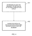
- a method comprising: determining at least one boundary for defining an active display area within a display, based on deformation input provided by a user; and causing the display to display an active display area defined by the determined at least one boundary.
- an apparatus comprising: means for determining at least one boundary for defining an active display area within a display, based on deformation input provided by a user; and means for causing the display to display an active display area defined by the determined at least one boundary.
- the means for determining the at least one boundary and the means for causing the display to display an active display area may be provided by at least one processor.
- an apparatus comprising: at least one processor and memory storing computer program code configured, working with the at least one processor, to cause at least the following to be performed: determining at least one boundary for defining an active display area within a display, based on deformation input provided by a user; and causing the display to display an active display area defined by the determined at least one boundary.
- computer program code that, when performed by at least one processor, causes at least the following to be performed: determining at least one boundary for defining an active display area within a display, based on deformation input provided by a user; and causing the display to display an active display area defined by the determined at least one boundary.
- the abovementioned computer program code may be stored on a non-transitory computer readable medium.
- a method comprising: determining an active display area within a display, based on user input; and causing the display to display the determined active display area.
- an apparatus comprising: means for determining an active display area within a display, based on user input; and means for causing the display to display the determined active display area.
- the means for determining the active display area and the means for causing the display to display the active display area may be provided by at least one processor.
- an apparatus comprising: at least one processor and memory storing computer program code configured, working with the at least one processor, to cause at least the following to be performed: determining an active display area within a display, based on user input; and causing the display to display the active display area.
- the abovementioned computer program code may be stored on a non-transitory computer readable medium.
- Embodiments of the invention relate to defining an active display area within a display of a device, based on deformation input detected by the device, and causing the active display area to be displayed on the display.
- a technical effect of at least some embodiments of the invention is that the user is provided with feedback regarding the deformation input that has been sensed by the device.
- a further technical effect of some embodiments of the invention is that power may be saved by rendering parts of the display at least partially inactive when the deformation input is provided.
- Figure 1 illustrates an apparatus 10 that may be a chip or a chipset.
- the apparatus 10 may form part of an electronic device such as that illustrated in figure 2 .
- the apparatus 10 comprises at least one processor 12 and at least one memory 14.
- a single processor 12 and a single memory 14 are shown in figure 1 for illustrative purposes.
- the processor 12 is configured to read from and write to the memory 14.
- the processor 12 may comprise an output interface via which data and/or commands are output by the processor 12 and an input interface via which data and/or commands are input to the processor 12.
- the memory 14 is illustrated as storing a computer program 17 which comprises computer program instructions/code 18 that control the operation of the apparatus 10 when loaded into the processor 12.
- the processor 12 by reading the memory, is able to load and execute the computer program code 18.
- the computer program code 18 provides the logic and routines that enables the apparatus 10 to perform the method illustrated in figure 4 and described below.
- the processor 12 and the computer program code 18 provide means for performing the method illustrated in figure 4 and described below.
- memory 14 is illustrated as a single component in figure 1 , it may be implemented as one or more separate components, some or all of which may be integrated/removable and/or may provide permanent/semi-permanent/dynamic/cached storage.
- the computer program code 18 may arrive at the apparatus 10 via any suitable delivery mechanism 28.
- the delivery mechanism 28 may be, for example, a non-transitory computer-readable storage medium such as an optical disc or a memory card.
- the delivery mechanism 28 may be a signal configured to reliably transfer the computer program code 18.
- the apparatus 10 may cause the propagation or transmission of the computer program code 18 as a computer data signal.
- Figure 2 illustrates an apparatus 20 in the form of an electronic device.
- the electronic device 20 may, for example, be a hand portable electronic device such as a mobile telephone, a tablet computer, a games console or a personal music player.
- the example of the electronic device 20 illustrated in figure 2 includes one or more deformation sensors 21, a display 22, one or more cameras 23, one or more orientation sensors 25 and the apparatus 10 illustrated in figure 1 co-located in a housing 24.
- the electronic device 20 might, for example, comprise other elements such as one or more radio frequency transceivers.
- the elements 12, 14, 21, 22, 23 and 25 are operationally coupled and any number or combination of intervening elements can exist between them (including no intervening elements).
- the processor 12 is configured to receive and process inputs from the deformation sensor(s) 21, the camera(s) 23 and the orientation sensor(s) 25.
- the display 22 is configured to display information under the control of the processor 12.
- the display 22 comprises an array of pixels, which may be arranged in columns and rows.
- the display 22 may be any type of display. It may, for example, be a liquid crystal display (LCD), an organic light emitting diode (OLED) display or a quantum dot display.
- the display 22 may or may not be a touch sensitive display.
- the one or more deformation sensors 21 are configured to sense deformation inputs provided by a user.
- a deformation input is a user input that causes the shape of the (body of the) apparatus 20 to deform at least temporarily, and at least in part.
- the deformation of the apparatus 20 may or may not be visible to the naked eye.
- the one or more deformation sensors 21 may, for example, include one or more pressure sensors and/or one or more strain gauges. In some embodiments, at least one deformation sensor may be integrated into the display 22. For instance, the display 22 may be pressure sensitive.
- the one or more cameras 23 may be one or more front facing cameras that are configured to detect a direction of a user's gaze.
- the one or more orientation sensors 25 are configured to detect an orientation of the apparatus 20, and may include one or more accelerometers and/or one or more gyroscopes.
- Fig. 3A illustrates a perspective view of an example of the second apparatus 20.
- the apparatus 20 illustrated in fig. 3A has a length L, a width W and a depth D.
- the length L is the same or greater than the width W.
- the width W is the same or greater than the depth D.
- the length L may be substantially perpendicular to the width W and/or the depth D.
- the width W may be substantially perpendicular to the depth D.
- the display 22 of the second apparatus 20 may comprise one or more faces. At least one face of the display 22 might not be parallel with at least one other face of the display 22. In the illustrated example, the display 22 has three faces, but only two faces 221, 222 can be seen.
- a first, main, face of the display 22 is labeled with the reference numeral 221 and has an outer surface which extends across the length L and the width W of the apparatus 20.
- a second, side, face of the display 22 is labeled with the reference numeral 222 and has an outer surface which extends across the length L and depth D of the apparatus 20.
- a third, side, face of the display 22 has an outer surface which is substantially parallel with the second face 222, substantially perpendicular to the first face 221, and extends across the length L and depth D of the apparatus 20.
- the second face 222 is separated from the third face by the width W of the apparatus 20.
- Each of the second and third faces is not parallel with the first face 221 and each of the second and third faces may be substantially perpendicular to the first face 221.
- the whole of each of the second and third faces is substantially perpendicular to the first face 221.
- the first, second and third faces of the display 22 are contiguous in that no aspect of the housing 24 separates one face from another. In other examples, one or more portions of the housing 24 may separate the first face 221 from the second face 222 and/or the third face.
- the display 22 When the display 22 is operational (that is, powered), it has an "active display area". In some instances, the active display area may encompass each and every pixel of the display 22. In other instances, the active display area does not encompass each and every pixel of the display 22 and, in those instances, the display 22 comprises an "inactive display area". The inactive display area is present, on the display 22, outside the active display area.
- the processor 12 is configured to switch off some or all of the pixels in the inactive display area. In other implementations, none of the pixels in the inactive display area are switched off. Irrespective of whether the pixels in the inactive display area are switched on or switched off, in circumstances where the active display area does not encompass each and every pixel of the display 22, at least one visible boundary within the outer bounds of the display 22 defines the active display area and the inactive display area. The active display area is located within the at least one boundary, and the inactive display area is located outside the at least one boundary.
- the inactive display area may be darker and/or dimmer than the active display area, and might be substantially black in color.
- the inactive display area might be substantially the same color as the housing 24.
- the active display area may or may not extend over one, some or all of the faces 221, 222 of the display 22.
- Two portions 241, 242 of the outer surface of the housing 24 are visible in fig. 3A , and form the bezel around the display 22.
- the outer surface of the housing 24 and the outer surface of the display 22 form at least part of the body of the apparatus 20. At least part of the apparatus 20 is deformable. In some examples, the housing 24 and the display 22 are deformable. In other examples, either the housing 24 or the display 22 is deformable. The deformation of the housing 24 and/or the display 22 may or may not be visible to the naked eye. The housing 24 and/or the display 22 may be deformable because it/they is/are bendable by a user.
- a deformation/bending input is provided by a user
- at least portion of the outer surface of the housing 24 and/or the display 22 is deformed/bent such that a curvature of the outer surface of the housing 24 and/or the display 22 changes while the deformation input is being applied.
- One or more portions of the housing 24 (outside of the display 22) may be displaced relative to other or more other portions of the housing 24 (outside of the display 22) when the deformation input is provided, due to the deformation of the housing 24 and/or the display 22.
- the housing 24 and/or the display 22 may be resilient such that when the user ceases to apply the deformation input, the housing 24 and/or the display 22 returns to its original position.
- the deformation sensor(s) 21 may be configured to sense a position and a magnitude of the deformation input applied by the user.
- a set of Cartesian coordinate axes 70 is illustrated in fig. 3A .
- the x-axis is considered to be parallel with a "coronal dimension”
- the y axis is considered to be parallel with a “vertical dimension”
- the z axis is considered to be parallel with a "sagittal dimension”.
- Fig. 3B illustrates a transverse plane 81 passing through the apparatus 20.
- a transverse plane 81 in this context, passes from posterior to anterior when the apparatus 20 is held in a landscape position and is parallel with the sagittal and coronal dimensions.
- a transverse plane 81 divides the apparatus 20 into inferior and superior parts when the apparatus 20 is held in a landscape position.
- Fig. 3C illustrates a coronal plane 82 passing through the apparatus 20.
- a coronal plane 82 passes, in this context, from inferior to superior when the apparatus 20 is held in a landscape position and is parallel with the vertical and coronal dimensions.
- a coronal plane 82 divides the apparatus 20 into anterior and posterior parts when the apparatus 20 is held in a landscape position.
- FIG. 3D illustrates a sagittal plane 83 passing through the apparatus 20.
- a sagittal plane 83 is parallel with the sagittal and vertical axes and divides the apparatus 20 into left and right parts when the apparatus 20 is held in a landscape position.
- the active display area might encompass the whole of the area of the display 22, such that the boundaries of the active display area are at the periphery of the display 22. That is, no pixels of the display 22 are located outside the boundaries of the active display area.
- a user deforms a body of the apparatus 20 and the one or more deformation sensors 21 provide one or more inputs to the processor 12 which indicate that the user is providing the deformation input.
- the processor 12 determines at least one boundary for defining an active display area with the display 22 based on the deformation input.
- the processor 12 causes the display 22 to display an active display area that is defined by the boundary/boundaries that was/were defined in block 401.
- the processor 12 may cause the position of the at least one boundary 41 to change gradually as the deformation input changes.
- the processor 12 responds to the deformation input by changing the position of the at least one boundary from the first position to a second position within the display 22 (meaning inside and spaced from the periphery of the display 22) in order to adjust the active display area.
- a user may change the deformation input that she is providing.
- the processor 12 may respond to a change in the deformation input by changing a position of at least one boundary from a first position (which could, for example, be at the periphery of the display 22 or within the display 22) to a second position within the display 22.
- the deformation input When the deformation input is changed, it may be that an axis about which the deformation input is provided changes, and/or a direction in which the deformation input is provided changes.
- a user provides a deformation input by applying first and second forces 101, 102 to the apparatus 20 as shown by the arrows labeled with the reference numerals 101 and 102.
- first and second forces 101, 102 In applying the first force 101 to the apparatus 20, the user is applying a first rotational force in a first direction about a vertical axis 71.
- the second force 102 is in a second direction about the axis 71 which is rotationally opposite to the first direction.
- the user might, for example, apply a third force at the rear of the apparatus 20 in the opposite direction to the first and second forces 101, 102 (and which is aligned with the axis 71 in the sagittal dimension), while applying the first and second forces 101, 102, in order to cause the apparatus 20 to bend about the axis 71.
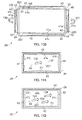
- the processor 12 determines at least one boundary 41 for defining an active display area 40 within the display 22 and causes the display to display the active display area 40 defined by the at least one boundary 41.
- the boundary 41 is visible on the side face 222 of the display 22 in fig. 5A .
- An inactive display area 42 is positioned outside the boundary 41.
- a boundary 41 defining the active display area 40 on a side face 222 of the display 22 is adjusted in response to the deformation input, but the boundaries defining the active display area 40 on the main face 221 of the display 22 are not adjusted.
- the position of the at least one boundary 41, and therefore the size and shape of the active display area 40 and the inactive display area 42, may depend upon the magnitude of the deformation input provided by the user (that is, the magnitude of the first and second forces 101, 102).
- the processor 12 may cause the at least one boundary 41 to change shape on the display 22 as the magnitude of the deformation input increases/decreases.
- the position of the at least one boundary 41, and therefore the size and/or shape of the active display area 40 and the inactive display area 42 may depend upon the position at which the deformation input is provided by the user.
- the processor 12 may cause the greatest change in the size and/or the shape of the active display area 40 to occur at or close to the location(s) at which the deformation input is provided.
- a technical effect of at least some embodiments of the invention is that the user is provided with feedback regarding the deformation input that has been sensed by the device.
- the sensed magnitude of the deformation input and/or the sensed location(s) of the deformation input may be conveyed to the user by the size and/or shape of the active display area 40.
- a user provides a deformation input by applying first and second forces 103, 104 to the apparatus 20 as shown by the arrows labeled with the reference numerals 103 and 104.
- the first force 103 that is applied in the fig. 5B example is applied in the opposite direction to the first force 101 in the fig. 5A example.
- the second force 104 that is applied in the fig. 5B example is applied in the opposite direction to the second force 102 in the fig. 5A example.
- the processor 12 may cause one or more user selectable graphical items to be displayed in the active display area 40 of the display 22.
- the processor 12 may be configured to refrain from displaying user selectable graphical items in the inactive display area 42 on the display 22.
- User selection of a graphical item displayed in the active display area 40 may cause the processor 12 to launch an application associated with the graphical item.
- the processor 12 may be configured to re-position the one or more graphical items and/or change the size and/or shape of the one or more graphical items as the boundary 41 and the active display area 40 change shape, such that the one or more graphical items continue to be displayed within the active display area 40.
- the one or more graphical items 50 may have been positioned on a portion of the display 22 that changes from being part of the active display area 40 to being part of the inactive display area 42 as the deformation input is applied.
- Fig. 5C illustrates a plurality of graphical items 50 displayed on the side face 222 of the display 22, in the active display area 40.
- the processor 12 has adjusted the size of some of the graphical items 50 when the active display area 40 was adjusted, based on deformation input provided by the user.
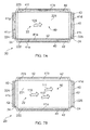
- Figures 6A to 10B illustrate an expanded plan view of another example of the apparatus 20 and its display 22.
- the display 22 includes first, second, third, fourth and fifth faces 221-225.
- the display 22 might not include one or more of the second, third, fourth and fifth faces 222-225.
- the display 22 comprises a main face 221 and four side faces 222-224.
- the first and second side faces have a similar form to those illustrated in figures 5A to 5C .
- the fourth face 224 has an outer surface which is substantially perpendicular to the first, second and third faces 221, 222, 223 and substantially parallel with the fifth face 225.
- the fourth face 224 extends across the length L and width W of the apparatus 20.
- the fifth face 225 has an outer surface which is substantially perpendicular to the first, second and third faces 221, 222, 223.
- the fifth face 225 extends across the length L and width W of the apparatus 20.
- the fifth face 225 is separated from the fourth face 224 by the length L of the apparatus 20.
- the first and fourth faces 221, 224 of the display 22 are not contiguous because a portion of the housing 24 separates the first face 221 from the fourth face 224.
- the first and fifth faces 221, 225 of the display 22 are not contiguous because a portion of the housing 24 separates the first face 221 from the fifth face 225.
- the first and fourth faces 221, 224 of the display 22 and/or the first and fifth faces 221, 225 of the display 22 may be contiguous.
- FIG 6A the arrows labeled with the reference numerals 105 and 106 indicate that a deformation input is provided by the user that is the same as that provided by the user in the figure 5A example.
- Figure 6A shows that the processor 12 has defined and caused display of a boundary 41 a for the active display area 40 which is positioned on the second face 222 of the display 22, and defined and caused display of a further boundary 41 b for the active display area 40 which is positioned on the third face 223 of the display 22.
- FIG 6B the arrows labeled with the reference numerals 107 and 108 indicate that a deformation input is provided by the user that is the same as that provided by the user in the figure 5B example.
- Figure 6B shows that the processor 12 has defined and caused display of boundaries 41a, 41b, 41c and 41 d for the active display area 40 which are positioned on the second, third, fourth and fifth faces 222-225 of the display 22.
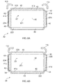
- FIG 7A the arrow labeled with the reference numeral 109 indicates that a deformation input is provided by the user at the main face 221 of the display 22, in the sagittal dimension.
- Figure 7A shows that the processor 12 has defined and caused display of boundaries 41a-41g for the active display area 40 which are positioned on the second, third, fourth and fifth faces 222-225 of the display 22.
- the example illustrated in figure 7A differs from previous examples in that some portions of the active display area 40 have been divided from other portions by boundaries 41 a to 41 d illustrated on the second, third, fourth and fifth faces 222-225 of the display 22.
- a deformation input is provided by the user at the main face 221 of the display 22, in the sagittal dimension.
- the arrows 110, 111 and 112 illustrate in figure 7B that a force is applied which is of a higher magnitude and/or applied across a wider area than that applied in the example illustrated in figure 7A .
- FIG. 7B shows that the processor 12 has defined and caused display of boundaries 41a to 41 d for the active display area 40 which are positioned on the second, third, fourth and fifth faces 222-225 of the display 22. It can be seen that, as the deformation input is of a higher magnitude and/or applied across a wider area in figure 7B than in figure 7A , the inactive display area 42 is greater in figure 7B than in figure 7A .
- the size of the inactive display area 42 increases and the size of the active display area 40 decreases. Portions of the display 22 which were part of the active display area 40 become part of the inactive display area 42.
- the increase in size of the inactive display area 42 is therefore the same as the decrease in size of the active display area 40.
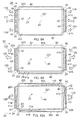
- FIG 8A the arrows labeled with the reference numerals 113 and 114 indicate that a deformation input is provided by the user by providing a rotational force about one or more sagittal axes.
- a first force 113 is applied in an anti-clockwise direction, while a second force 114 is applied in a clockwise direction.
- Figure 8A shows that the processor 12 has defined and caused display of boundaries 41b-41d for the active display area 40 which are positioned on the third, fourth and fifth faces 223-225 of the display 22.
- FIG 8B the arrows labeled with the reference numerals 115 and 116 indicate that a deformation input is provided by the user by applying rotational forces about one or more sagittal axes.
- a first force 115 is applied in a clockwise direction, in the opposite direction from the first force 113 which was applied in figure 8A .
- a second rotational force 116 is applied in an anti-clockwise direction, opposite to the direction in which the second force 114 is applied in the figure 8A example.
- Figure 8B shows that the processor 12 has defined and caused display of boundaries 41 a, 41 c and 41 d for the active display area 40 which are positioned on the second, fourth and fifth faces 222, 224 and 225 of the display 22.
- the user grips the apparatus 20 by placing two fingers of each hand behind the apparatus 20 and by placing his thumbs on the front surface of the apparatus 20.
- the user pushes forwards with his thumbs, as indicated by the arrows 117 and 120 illustrated in figure 9A , and pushes the apparatus 20 towards himself, from behind, as illustrated by the arrows 116, 118, 119 and 121 in figure 9A .
- Figure 9A shows that the processor 12 has defined and caused display of boundaries 41 c, 41 d, 41 g and 41 h for the active display area 40 on the fourth and fifth faces 224, 225 of the display 22. Portions of the inactive display area 42 are provided on the fourth and fifth faces 224, 225 of the display 22 but not on the first, second and third faces 221-223 of the display 22.
- the example illustrated in figure 9B differs from the example illustrated in figure 9A in that each force which was applied in the figure 9A example is applied in the opposite direction in the figure 9B example.
- the processor has defined and caused display of boundaries 41a, 41b, 41c, 41 d, 41g and 41h for the active display area 40 which are positioned on the second, third, fourth and fifth faces 222-225 of the display 22.
- Some portions of the inactive display area 42 separate some portions of the active display area 40 from other portions of the active display area 40.
- FIG 10A the arrows labeled with the reference numerals 128 and 129 indicate that a deformation input is provided by a user by providing a first rotational force 128 and a second rotational force 129 about one or more vertical axes.
- the first and second forces 128, 129 are in substantially the same rotational direction.
- Figure 10A shows that the processor 12 has defined and caused display of boundaries 41 a-41 h for the active display area 40 on the second, third, fourth and fifth faces 222-225 of the display 22. It can also be seen that some portions of the active display area 40 are separated from other portions of the active display area 40 by portions of the inactive display area 42.
- FIG 10B rotational forces 130 and 131 are applied which are in an opposite direction to those that are applied in the figure 10A example.
- Figure 10B shows that the processor 12 has defined and caused display of boundaries 41a-41h for the active display area 40 on the second, third, fourth and fifth faces 222-225 of the display 22. It can also be seen that some portions of the active display area 40 are separated from other portions of the active display area 40 by portions of the inactive display area 42.
- Figures 11A and 11B illustrate an additional example of the apparatus 20 which does not include the second, third, fourth and fifth faces 222-225 of the display 22.
- the display 22 consists of the main face 221.
- the processor 12 defines and causes display of boundaries 41i-41l for the active display area 40 on the main face 221 of the display 22.
- Figure 11B illustrates an example where the force that is applied to the main face 221 of the display 22 is of a greater magnitude and/or applied across a wider area than that in the figure 11A example, as indicated by the arrows 133, 134 and 135 in figure 11B .
- the deformation input may be provided using a single digit in the figure 11A example and multiple digits in the 11 B example.
- the size of the inactive display area 42 increases and the size of the active display area 40 decreases. Portions of the display 22 which were part of the active display area 40 become part of the inactive display area 42.
- the increase in size of the inactive display area 42 is therefore the same as the decrease in size of the active display area 40.
- the size and shape of the active display area 40 and the inactive display area 42 may differ from those illustrated in the appended figures.
- at least one boundary which is defined by the processor 12 may be defined based on a user gaze direction and/or an orientation of the apparatus 20.
- the processor 12 may use inputs from the one or more cameras 23 to determine the user gaze direction.
- the size and/or shape of the active display area 40 and the inactive display area 42 may then depend on the user gaze direction.
- the user may receive inputs from the one or more orientation sensors 25 to determine an orientation of the apparatus 20.
- the size and/or shape of the active display area 40 and the inactive display area 42 may then depend upon the determined orientation.
- references to 'computer-readable medium', 'computer', 'processor' etc. should be understood to encompass not only computers having different architectures such as single/multi-processor architectures and sequential (Von Neumann)/parallel architectures but also specialized circuits such as field-programmable gate arrays (FPGA), application specific circuits (ASIC), signal processing devices and other processing circuitry.
- References to computer program instructions, code etc. should be understood to encompass software for a programmable processor or firmware such as, for example, the programmable content of a hardware device whether instructions for a processor, or configuration settings for a fixed-function device, gate array or programmable logic device etc.
- circuitry refers to all of the following:
- circuitry would also cover an implementation of merely a processor (or multiple processors) or portion of a processor and its (or their) accompanying software and/or firmware.
- circuitry would also cover, for example and if applicable to the particular claim element, a baseband integrated circuit or applications processor integrated circuit for a mobile phone or a similar integrated circuit in a server, a cellular network device, or other network device.
- the blocks illustrated in fig 11 may represent actions in a method and/or sections of code in the computer program 17.
- the illustration of a particular order to the blocks does not necessarily imply that there is a required or preferred order for the blocks and the order and arrangement of the block may be varied. Furthermore, it may be possible for some blocks to be omitted.
- the size and shape of the apparatus 20 illustrated in figures 3A to 11B may be different from those illustrated.
- the display 22 may have more or fewer faces 221-225 than those illustrated in figures 3A to 11B and those faces 221-225 may be at different angles relative to one another than that illustrated in figures 3A to 11B .
- deformation inputs A number of different types of deformation input are described in the examples provided above. It will be appreciated by those skilled in the art that other types of deformation input may be provided in other examples which fall within the scope of the claims, such as squeezing deformation inputs and twisting deformation inputs.
Landscapes
- Engineering & Computer Science (AREA)
- Theoretical Computer Science (AREA)
- General Engineering & Computer Science (AREA)
- Physics & Mathematics (AREA)
- General Physics & Mathematics (AREA)
- Human Computer Interaction (AREA)
- Computer Hardware Design (AREA)
- User Interface Of Digital Computer (AREA)
Priority Applications (1)
| Application Number | Priority Date | Filing Date | Title |
|---|---|---|---|
| EP14176199.9A EP2966543B1 (fr) | 2014-07-08 | 2014-07-08 | Gestion d'affichage |
Applications Claiming Priority (1)
| Application Number | Priority Date | Filing Date | Title |
|---|---|---|---|
| EP14176199.9A EP2966543B1 (fr) | 2014-07-08 | 2014-07-08 | Gestion d'affichage |
Publications (2)
| Publication Number | Publication Date |
|---|---|
| EP2966543A1 true EP2966543A1 (fr) | 2016-01-13 |
| EP2966543B1 EP2966543B1 (fr) | 2018-10-10 |
Family
ID=51176935
Family Applications (1)
| Application Number | Title | Priority Date | Filing Date |
|---|---|---|---|
| EP14176199.9A Active EP2966543B1 (fr) | 2014-07-08 | 2014-07-08 | Gestion d'affichage |
Country Status (1)
| Country | Link |
|---|---|
| EP (1) | EP2966543B1 (fr) |
Citations (4)
| Publication number | Priority date | Publication date | Assignee | Title |
|---|---|---|---|---|
| US20130076649A1 (en) * | 2011-09-27 | 2013-03-28 | Scott A. Myers | Electronic Devices With Sidewall Displays |
| EP2584438A2 (fr) * | 2011-10-20 | 2013-04-24 | Samsung Electronics Co., Ltd. | Dispositif d'affichage flexible |
| US20130145311A1 (en) * | 2011-12-05 | 2013-06-06 | Samsung Electronics Co., Ltd | Method and apparatus for controlling a display in a portable terminal |
| US20140015743A1 (en) * | 2012-07-11 | 2014-01-16 | Samsung Electronics Co., Ltd. | Flexible display apparatus and operating method thereof |
-
2014
- 2014-07-08 EP EP14176199.9A patent/EP2966543B1/fr active Active
Patent Citations (4)
| Publication number | Priority date | Publication date | Assignee | Title |
|---|---|---|---|---|
| US20130076649A1 (en) * | 2011-09-27 | 2013-03-28 | Scott A. Myers | Electronic Devices With Sidewall Displays |
| EP2584438A2 (fr) * | 2011-10-20 | 2013-04-24 | Samsung Electronics Co., Ltd. | Dispositif d'affichage flexible |
| US20130145311A1 (en) * | 2011-12-05 | 2013-06-06 | Samsung Electronics Co., Ltd | Method and apparatus for controlling a display in a portable terminal |
| US20140015743A1 (en) * | 2012-07-11 | 2014-01-16 | Samsung Electronics Co., Ltd. | Flexible display apparatus and operating method thereof |
Also Published As
| Publication number | Publication date |
|---|---|
| EP2966543B1 (fr) | 2018-10-10 |
Similar Documents
| Publication | Publication Date | Title |
|---|---|---|
| EP3410252B1 (fr) | Dispositif électronique comprenant un module monté dans la zone creuse d'une couche | |
| KR102561172B1 (ko) | 디스플레이 내에 카메라 모듈이 포함된 전자 장치 및 상기 카메라 모듈 주변의 이미지를 보정하는 방법 | |
| US11228091B2 (en) | Electronic device including antenna using structure of display panel | |
| KR102256677B1 (ko) | 플렉서블 표시장치 및 이의 영상 표시방법 | |
| US20180224963A1 (en) | Electronic device for variably displaying display position of object on expansion area of display and method of displaying | |
| US9804734B2 (en) | Method, apparatus and computer program for displaying content | |
| US9983729B2 (en) | Method, an apparatus and a computer program for controlling an output from a display of an apparatus | |
| US20130093753A1 (en) | Auto-stereoscopic display control | |
| US10996743B2 (en) | Electronic system and controller and the operating method for the same | |
| TW201351206A (zh) | 多段式可穿戴型配件(二) | |
| EP3722931A1 (fr) | Dispositif électronique d'acquisition d'une entrée d'utilisateur en état submergé à l'aide d'un capteur de pression, et procédé de commande de dispositif électronique | |
| US10353569B2 (en) | Crop frame adjusting method, image processing device, and non-transitory computer readable storage medium | |
| US11531419B2 (en) | Electronic device for identifying coordinates of external object touching touch sensor | |
| CN110998497A (zh) | 包含力传感器的电子装置及其电子装置控制方法 | |
| US11275470B2 (en) | Electronic device including display and method for correcting image displayed by electronic device | |
| KR20210015489A (ko) | 휠 입력을 처리하는 전자 장치 및 이의 동작 방법 | |
| KR20180090366A (ko) | Vr 뷰어에서의 휴대용 사용자 디바이스의 정렬을 위한 전도성 접촉부들 | |
| CN114868099A (zh) | 抗滑移注视跟踪用户界面 | |
| EP2966543B1 (fr) | Gestion d'affichage | |
| EP3309660B1 (fr) | Procédé destiné à la détection de dispositif d'entrée et dispositif de détection | |
| WO2010081074A1 (fr) | Souris d'ordinateur | |
| CN105739684B (zh) | 具有手势校准机制的电子系统及其操作方法 | |
| US9710073B2 (en) | Detachable device case having an auxiliary touch input device and data handling capability | |
| US9338432B1 (en) | Mobile device with 3-dimensional user interface | |
| CN115936098B (zh) | 神经网络处理方法、装置、存储介质及电子设备 |
Legal Events
| Date | Code | Title | Description |
|---|---|---|---|
| PUAI | Public reference made under article 153(3) epc to a published international application that has entered the european phase |
Free format text: ORIGINAL CODE: 0009012 |
|
| AK | Designated contracting states |
Kind code of ref document: A1 Designated state(s): AL AT BE BG CH CY CZ DE DK EE ES FI FR GB GR HR HU IE IS IT LI LT LU LV MC MK MT NL NO PL PT RO RS SE SI SK SM TR |
|
| AX | Request for extension of the european patent |
Extension state: BA ME |
|
| 17P | Request for examination filed |
Effective date: 20160711 |
|
| RBV | Designated contracting states (corrected) |
Designated state(s): AL AT BE BG CH CY CZ DE DK EE ES FI FR GB GR HR HU IE IS IT LI LT LU LV MC MK MT NL NO PL PT RO RS SE SI SK SM TR |
|
| STAA | Information on the status of an ep patent application or granted ep patent |
Free format text: STATUS: EXAMINATION IS IN PROGRESS |
|
| 17Q | First examination report despatched |
Effective date: 20161208 |
|
| REG | Reference to a national code |
Ref country code: DE Ref legal event code: R079 Ref document number: 602014033677 Country of ref document: DE Free format text: PREVIOUS MAIN CLASS: G06F0003010000 Ipc: G09G0003200000 |
|
| GRAP | Despatch of communication of intention to grant a patent |
Free format text: ORIGINAL CODE: EPIDOSNIGR1 |
|
| STAA | Information on the status of an ep patent application or granted ep patent |
Free format text: STATUS: GRANT OF PATENT IS INTENDED |
|
| RIC1 | Information provided on ipc code assigned before grant |
Ipc: G06F 3/048 20130101ALI20180412BHEP Ipc: G06F 3/01 20060101ALI20180412BHEP Ipc: G06F 1/16 20060101ALI20180412BHEP Ipc: G09G 3/20 20060101AFI20180412BHEP Ipc: H04M 1/02 20060101ALI20180412BHEP |
|
| INTG | Intention to grant announced |
Effective date: 20180504 |
|
| GRAS | Grant fee paid |
Free format text: ORIGINAL CODE: EPIDOSNIGR3 |
|
| GRAA | (expected) grant |
Free format text: ORIGINAL CODE: 0009210 |
|
| STAA | Information on the status of an ep patent application or granted ep patent |
Free format text: STATUS: THE PATENT HAS BEEN GRANTED |
|
| AK | Designated contracting states |
Kind code of ref document: B1 Designated state(s): AL AT BE BG CH CY CZ DE DK EE ES FI FR GB GR HR HU IE IS IT LI LT LU LV MC MK MT NL NO PL PT RO RS SE SI SK SM TR |
|
| REG | Reference to a national code |
Ref country code: GB Ref legal event code: FG4D |
|
| REG | Reference to a national code |
Ref country code: CH Ref legal event code: EP Ref country code: AT Ref legal event code: REF Ref document number: 1052168 Country of ref document: AT Kind code of ref document: T Effective date: 20181015 |
|
| REG | Reference to a national code |
Ref country code: IE Ref legal event code: FG4D |
|
| REG | Reference to a national code |
Ref country code: DE Ref legal event code: R096 Ref document number: 602014033677 Country of ref document: DE |
|
| REG | Reference to a national code |
Ref country code: NL Ref legal event code: FP |
|
| REG | Reference to a national code |
Ref country code: LT Ref legal event code: MG4D |
|
| REG | Reference to a national code |
Ref country code: AT Ref legal event code: MK05 Ref document number: 1052168 Country of ref document: AT Kind code of ref document: T Effective date: 20181010 |
|
| PG25 | Lapsed in a contracting state [announced via postgrant information from national office to epo] |
Ref country code: ES Free format text: LAPSE BECAUSE OF FAILURE TO SUBMIT A TRANSLATION OF THE DESCRIPTION OR TO PAY THE FEE WITHIN THE PRESCRIBED TIME-LIMIT Effective date: 20181010 Ref country code: LV Free format text: LAPSE BECAUSE OF FAILURE TO SUBMIT A TRANSLATION OF THE DESCRIPTION OR TO PAY THE FEE WITHIN THE PRESCRIBED TIME-LIMIT Effective date: 20181010 Ref country code: AT Free format text: LAPSE BECAUSE OF FAILURE TO SUBMIT A TRANSLATION OF THE DESCRIPTION OR TO PAY THE FEE WITHIN THE PRESCRIBED TIME-LIMIT Effective date: 20181010 Ref country code: FI Free format text: LAPSE BECAUSE OF FAILURE TO SUBMIT A TRANSLATION OF THE DESCRIPTION OR TO PAY THE FEE WITHIN THE PRESCRIBED TIME-LIMIT Effective date: 20181010 Ref country code: IS Free format text: LAPSE BECAUSE OF FAILURE TO SUBMIT A TRANSLATION OF THE DESCRIPTION OR TO PAY THE FEE WITHIN THE PRESCRIBED TIME-LIMIT Effective date: 20190210 Ref country code: BG Free format text: LAPSE BECAUSE OF FAILURE TO SUBMIT A TRANSLATION OF THE DESCRIPTION OR TO PAY THE FEE WITHIN THE PRESCRIBED TIME-LIMIT Effective date: 20190110 Ref country code: HR Free format text: LAPSE BECAUSE OF FAILURE TO SUBMIT A TRANSLATION OF THE DESCRIPTION OR TO PAY THE FEE WITHIN THE PRESCRIBED TIME-LIMIT Effective date: 20181010 Ref country code: PL Free format text: LAPSE BECAUSE OF FAILURE TO SUBMIT A TRANSLATION OF THE DESCRIPTION OR TO PAY THE FEE WITHIN THE PRESCRIBED TIME-LIMIT Effective date: 20181010 Ref country code: NO Free format text: LAPSE BECAUSE OF FAILURE TO SUBMIT A TRANSLATION OF THE DESCRIPTION OR TO PAY THE FEE WITHIN THE PRESCRIBED TIME-LIMIT Effective date: 20190110 Ref country code: LT Free format text: LAPSE BECAUSE OF FAILURE TO SUBMIT A TRANSLATION OF THE DESCRIPTION OR TO PAY THE FEE WITHIN THE PRESCRIBED TIME-LIMIT Effective date: 20181010 |
|
| PG25 | Lapsed in a contracting state [announced via postgrant information from national office to epo] |
Ref country code: RS Free format text: LAPSE BECAUSE OF FAILURE TO SUBMIT A TRANSLATION OF THE DESCRIPTION OR TO PAY THE FEE WITHIN THE PRESCRIBED TIME-LIMIT Effective date: 20181010 Ref country code: GR Free format text: LAPSE BECAUSE OF FAILURE TO SUBMIT A TRANSLATION OF THE DESCRIPTION OR TO PAY THE FEE WITHIN THE PRESCRIBED TIME-LIMIT Effective date: 20190111 Ref country code: PT Free format text: LAPSE BECAUSE OF FAILURE TO SUBMIT A TRANSLATION OF THE DESCRIPTION OR TO PAY THE FEE WITHIN THE PRESCRIBED TIME-LIMIT Effective date: 20190210 Ref country code: SE Free format text: LAPSE BECAUSE OF FAILURE TO SUBMIT A TRANSLATION OF THE DESCRIPTION OR TO PAY THE FEE WITHIN THE PRESCRIBED TIME-LIMIT Effective date: 20181010 Ref country code: AL Free format text: LAPSE BECAUSE OF FAILURE TO SUBMIT A TRANSLATION OF THE DESCRIPTION OR TO PAY THE FEE WITHIN THE PRESCRIBED TIME-LIMIT Effective date: 20181010 |
|
| REG | Reference to a national code |
Ref country code: DE Ref legal event code: R097 Ref document number: 602014033677 Country of ref document: DE |
|
| PG25 | Lapsed in a contracting state [announced via postgrant information from national office to epo] |
Ref country code: CZ Free format text: LAPSE BECAUSE OF FAILURE TO SUBMIT A TRANSLATION OF THE DESCRIPTION OR TO PAY THE FEE WITHIN THE PRESCRIBED TIME-LIMIT Effective date: 20181010 Ref country code: IT Free format text: LAPSE BECAUSE OF FAILURE TO SUBMIT A TRANSLATION OF THE DESCRIPTION OR TO PAY THE FEE WITHIN THE PRESCRIBED TIME-LIMIT Effective date: 20181010 Ref country code: DK Free format text: LAPSE BECAUSE OF FAILURE TO SUBMIT A TRANSLATION OF THE DESCRIPTION OR TO PAY THE FEE WITHIN THE PRESCRIBED TIME-LIMIT Effective date: 20181010 |
|
| PLBE | No opposition filed within time limit |
Free format text: ORIGINAL CODE: 0009261 |
|
| STAA | Information on the status of an ep patent application or granted ep patent |
Free format text: STATUS: NO OPPOSITION FILED WITHIN TIME LIMIT |
|
| PG25 | Lapsed in a contracting state [announced via postgrant information from national office to epo] |
Ref country code: RO Free format text: LAPSE BECAUSE OF FAILURE TO SUBMIT A TRANSLATION OF THE DESCRIPTION OR TO PAY THE FEE WITHIN THE PRESCRIBED TIME-LIMIT Effective date: 20181010 Ref country code: SK Free format text: LAPSE BECAUSE OF FAILURE TO SUBMIT A TRANSLATION OF THE DESCRIPTION OR TO PAY THE FEE WITHIN THE PRESCRIBED TIME-LIMIT Effective date: 20181010 Ref country code: SM Free format text: LAPSE BECAUSE OF FAILURE TO SUBMIT A TRANSLATION OF THE DESCRIPTION OR TO PAY THE FEE WITHIN THE PRESCRIBED TIME-LIMIT Effective date: 20181010 Ref country code: EE Free format text: LAPSE BECAUSE OF FAILURE TO SUBMIT A TRANSLATION OF THE DESCRIPTION OR TO PAY THE FEE WITHIN THE PRESCRIBED TIME-LIMIT Effective date: 20181010 |
|
| RAP2 | Party data changed (patent owner data changed or rights of a patent transferred) |
Owner name: NOKIA TECHNOLOGIES OY |
|
| 26N | No opposition filed |
Effective date: 20190711 |
|
| PG25 | Lapsed in a contracting state [announced via postgrant information from national office to epo] |
Ref country code: SI Free format text: LAPSE BECAUSE OF FAILURE TO SUBMIT A TRANSLATION OF THE DESCRIPTION OR TO PAY THE FEE WITHIN THE PRESCRIBED TIME-LIMIT Effective date: 20181010 |
|
| PG25 | Lapsed in a contracting state [announced via postgrant information from national office to epo] |
Ref country code: MC Free format text: LAPSE BECAUSE OF FAILURE TO SUBMIT A TRANSLATION OF THE DESCRIPTION OR TO PAY THE FEE WITHIN THE PRESCRIBED TIME-LIMIT Effective date: 20181010 |
|
| REG | Reference to a national code |
Ref country code: CH Ref legal event code: PL |
|
| GBPC | Gb: european patent ceased through non-payment of renewal fee |
Effective date: 20190708 |
|
| PG25 | Lapsed in a contracting state [announced via postgrant information from national office to epo] |
Ref country code: TR Free format text: LAPSE BECAUSE OF FAILURE TO SUBMIT A TRANSLATION OF THE DESCRIPTION OR TO PAY THE FEE WITHIN THE PRESCRIBED TIME-LIMIT Effective date: 20181010 |
|
| PG25 | Lapsed in a contracting state [announced via postgrant information from national office to epo] |
Ref country code: GB Free format text: LAPSE BECAUSE OF NON-PAYMENT OF DUE FEES Effective date: 20190708 |
|
| PG25 | Lapsed in a contracting state [announced via postgrant information from national office to epo] |
Ref country code: CH Free format text: LAPSE BECAUSE OF NON-PAYMENT OF DUE FEES Effective date: 20190731 Ref country code: LU Free format text: LAPSE BECAUSE OF NON-PAYMENT OF DUE FEES Effective date: 20190708 Ref country code: LI Free format text: LAPSE BECAUSE OF NON-PAYMENT OF DUE FEES Effective date: 20190731 |
|
| PG25 | Lapsed in a contracting state [announced via postgrant information from national office to epo] |
Ref country code: FR Free format text: LAPSE BECAUSE OF NON-PAYMENT OF DUE FEES Effective date: 20190731 |
|
| PG25 | Lapsed in a contracting state [announced via postgrant information from national office to epo] |
Ref country code: IE Free format text: LAPSE BECAUSE OF NON-PAYMENT OF DUE FEES Effective date: 20190708 |
|
| PG25 | Lapsed in a contracting state [announced via postgrant information from national office to epo] |
Ref country code: CY Free format text: LAPSE BECAUSE OF FAILURE TO SUBMIT A TRANSLATION OF THE DESCRIPTION OR TO PAY THE FEE WITHIN THE PRESCRIBED TIME-LIMIT Effective date: 20181010 |
|
| PG25 | Lapsed in a contracting state [announced via postgrant information from national office to epo] |
Ref country code: HU Free format text: LAPSE BECAUSE OF FAILURE TO SUBMIT A TRANSLATION OF THE DESCRIPTION OR TO PAY THE FEE WITHIN THE PRESCRIBED TIME-LIMIT; INVALID AB INITIO Effective date: 20140708 Ref country code: MT Free format text: LAPSE BECAUSE OF FAILURE TO SUBMIT A TRANSLATION OF THE DESCRIPTION OR TO PAY THE FEE WITHIN THE PRESCRIBED TIME-LIMIT Effective date: 20181010 |
|
| PG25 | Lapsed in a contracting state [announced via postgrant information from national office to epo] |
Ref country code: MK Free format text: LAPSE BECAUSE OF FAILURE TO SUBMIT A TRANSLATION OF THE DESCRIPTION OR TO PAY THE FEE WITHIN THE PRESCRIBED TIME-LIMIT Effective date: 20181010 |
|
| P01 | Opt-out of the competence of the unified patent court (upc) registered |
Effective date: 20230527 |
|
| PGFP | Annual fee paid to national office [announced via postgrant information from national office to epo] |
Ref country code: NL Payment date: 20250613 Year of fee payment: 12 Ref country code: BE Payment date: 20250619 Year of fee payment: 12 |
|
| PGFP | Annual fee paid to national office [announced via postgrant information from national office to epo] |
Ref country code: DE Payment date: 20250604 Year of fee payment: 12 |