EP2966627A1 - Coffre doté de capteur inductif destiné à déterminer la position d'éléments mobiles - Google Patents
Coffre doté de capteur inductif destiné à déterminer la position d'éléments mobiles Download PDFInfo
- Publication number
- EP2966627A1 EP2966627A1 EP14176710.3A EP14176710A EP2966627A1 EP 2966627 A1 EP2966627 A1 EP 2966627A1 EP 14176710 A EP14176710 A EP 14176710A EP 2966627 A1 EP2966627 A1 EP 2966627A1
- Authority
- EP
- European Patent Office
- Prior art keywords
- cashbox
- coil
- movable
- movable element
- movement
- Prior art date
- Legal status (The legal status is an assumption and is not a legal conclusion. Google has not performed a legal analysis and makes no representation as to the accuracy of the status listed.)
- Granted
Links
Images



Classifications
-
- G—PHYSICS
- G07—CHECKING-DEVICES
- G07D—HANDLING OF COINS OR VALUABLE PAPERS, e.g. TESTING, SORTING BY DENOMINATIONS, COUNTING, DISPENSING, CHANGING OR DEPOSITING
- G07D11/00—Devices accepting coins; Devices accepting, dispensing, sorting or counting valuable papers
- G07D11/20—Controlling or monitoring the operation of devices; Data handling
- G07D11/22—Means for sensing or detection
- G07D11/23—Means for sensing or detection for sensing the quantity of valuable papers in containers
Definitions
- the invention relates to a cashbox comprising a receiving area for receiving banknotes and at least one movable element for limiting this receiving area. Furthermore, a sensor for determining the position of the movable element is provided.
- the movable element is in particular a side limiter or a pressure unit.
- a pressure unit is provided by means of which the notes of value received in the receiving area are biased in the direction of a supply and / or removal opening.
- the pressure unit ensures that the banknotes of the banknote stack are always kept below a minimum pressure and tipping is prevented and secure removal and delivery is guaranteed.
- the pressure unit is arranged in the feed direction of the notes of value and counter to the feed of the notes of value movable within the cashbox.
- cash cassettes have side limiters which are relative to the side walls of the cash box in the receiving area are movable into it, so as to adjust the width of the recording area.
- these sobegrenzer be used to adjust the width of the receiving area to the width of the recorded notes of value.
- resistive sensors are used to determine the position of the pressure unit. About the determined position of the pressure unit can then be determined the stock of the cashbox of notes of value.
- the positions of the page delimiter can be determined via resistive elements, so that incorrect settings can also be easily detected here.
- resistive sensors have the disadvantage that they are susceptible to dirt. Especially with used banknotes, however, it can quickly happen that pollution occurs. In addition, such resistive sensors are prone to error and must be replaced frequently due to the pressure constantly applied. Also, the cost of such sensors is relatively high and the installation is complicated.
- the document DE 101 95 314 T5 describes the determination of the stock of coin stores by means of photo sensors.
- the senor comprises at least one inductive sensor, with the aid of which the position of the movable
- inductive sensors can be determined.
- the use of inductive sensors has the advantage that they are compact, are less susceptible to contamination, can be purchased inexpensively and are very easy to install.
- inductive sensors allow a space-saving design and a very accurate determination of the position.
- the movable element is, in particular, a side limiter for adapting the width of the receiving area to the size of the notes of value to be received.
- This Sobeskyr is arranged in particular adjustable on a side wall of the housing of the cashbox relative to this.
- the movable element may also be a pressure unit for biasing the notes of value received in the receiving area in the direction of an opening for removing and / or feeding notes of the cash box.
- This pressure unit is arranged in particular in a supply direction of the notes of value and counter to this feeding direction of the notes of value movable within the receiving area of the cashbox and designed such that their position is changed depending on the number of recorded notes of value such that the notes of value are always below a minimum pressure.
- a plurality of movable elements in particular a pressure unit and two Sobegrenzer be provided. It is also possible that a separate inductive sensor is provided for each movable element, with the aid of which the position of this movable element can be determined. In particular, each of these sensors can be further developed as described below.
- only one inductive sensor can be provided for determining the position of at least two movable elements.
- the cash box comprises a control unit which determines the fill level of the cash box on bank notes as a function of the position of the press unit.
- the inductive sensor serves as a level sensor, with the help of which very accurately the number of recorded in the receiving area of the money cassettes banknotes can be determined.
- the inductive sensor comprises a coil arrangement for generating an alternating magnetic field and a metallic element which is movable relative to the alternating magnetic field, so that the metallic element influences the alternating magnetic field differently depending on the relative position between the coil arrangement and the metallic element.
- the inductive sensor has a sensor circuit which is a change of the alternating magnetic field, in particular the influence of the alternating magnetic field in dependence determines the relative position of the metallic element relative to the coil assembly.
- the sensor unit may comprise a control unit, in particular a microcontroller, which evaluates the change in the alternating magnetic field determined by the sensor circuit and, in particular, outputs it to a control unit of the cashbox.
- the microcontroller may also be part of the control unit of the cashbox.
- the metallic element is formed in particular in the form of a metallic strip, whereby a particularly compact and simple construction is achieved.
- the inductive sensor may comprise a power supply unit, for example a battery or an accumulator.
- the power supply of the inductive sensor can also be done centrally via the power supply of the cashbox.
- the coil arrangement is designed in particular in the form of a printed circuit, resulting in a particularly flat, compact construction. In addition, over Such printed circuits can also be easily made more complex coil shapes.
- the coil arrangement may comprise only one or more coils.
- the transmitter circuit is designed in particular in the form of an integrated circuit, so that this is designed to be particularly simple and space-saving.
- the sensor circuit is connected in particular via a cable to the coil of the coil arrangement.
- the microcontroller is arranged in particular on the same board as the integrated circuit. Alternatively, the microcontroller may also be attached to another component of the cashbox.
- microcontrollers instead of a microcontroller, microprocessors, CPLDs, DSPs, PSOCs, memory-based state machines and / or preconfigured sensors without microcontrollers can also be used as the control unit.
- the inductive sensor comprises at least one further coil arrangement for generating a further alternating magnetic field.
- the accuracy of the inductive sensor can be further increased.
- a differential measurement can be achieved hereby. For example, this manufacturing tolerances and / or changes in the distance between the metallic element and the coil assembly can be determined and taken into account in the evaluation accordingly.
- the metallic element is arranged on the movable element.
- the coil assembly is then arranged stationary relative to the housing of the cashbox and in particular arranged such that the metallic element is moved along with this movable element on the coil assembly in the direction of movement of the movable member when moving the movable member.
- the metallic element is in particular formed as a metal strip and arranged on the cartridge bottom of the cashbox facing side of the movable element.
- the metallic element takes up very little space and can be easily attached to existing movable elements, such as side limiters or pressure units from below.
- the coil assembly is in particular formed as a extending in the direction of movement of the movable member board which is arranged on the cassette bottom, that the metallic element is moved when moving the movable member at a predetermined distance over the coil assembly.
- the coil or the Coil arrangement is for this purpose in particular designed such that the magnetic alternating field generated by it in the direction of movement of the movable element is formed differently at least within the adjustment of the movable element at each position, so that depending on the position of the metallic element by this a different influence on the inductive sensor he follows.
- the adjustment range is to be understood as meaning, in particular, that region within which the movable element can be adjusted according to plan.
- the coil arrangement comprises in particular a plurality of coils connected in series, wherein these coils are arranged one behind the other in the direction of movement of the movable element.
- the coils in this case have different numbers of turns, so that the metallic element, depending on which is arranged above which of these coils, has a different influence on the magnetic alternating field generated by the coil assembly. This influence can be easily determined by the inductive sensor.
- the coil assembly may also comprise only one coil, which is designed such that the distance between their turns to each other in the direction of movement of the movable member, so in turn depending on the position of the metallic element relative to the coil assembly that through the coil assembly produced differently influenced magnetic alternating field.
- the coil arrangement can also be arranged on the movable element and, correspondingly, the metallic element can be arranged in a stationary manner relative to the housing of the cashbox.
- the metallic element is arranged in this case such that the coil assembly is transported along with the moving element in the direction of movement when moving the movable member along with these.
- the coil arrangement is preferably also formed in the form of a printed circuit board in this case.
- a simple conventional coil can be used. It is not necessary to connect a plurality of coils in series, and no complex coil with varying pitches has to be used.
- the coil arrangement is arranged in particular on the side of the movable element facing the cassette bottom.
- a film print can also be used.
- the metallic element is formed in this embodiment as a extending in the direction of movement of the movable member board with a metal strip.
- a metal strip without board can be used.
- the metal strip is disposed on the cassette bottom such that the coil assembly moves of the movable member is moved over the metal strip at a predetermined distance.
- the width of the metal strip is seen in the direction of movement of the movable element at least within the adjustment of the movable element positionally different.
- the metallic strip in turn affects the alternating magnetic field generated by the coil assembly depending on the relative position of the coil assembly and thus the relative position of the movable member to the metallic strip differently, so that the position of the movable member can be determined easily and accurately.
- the metal strip is triangular in shape so that the width changes continuously uniformly in the direction of movement and thus the position of the movable element can be determined in a particularly simple manner.
- FIG. 1 is a schematic perspective view of a cashbox 10 according to a first embodiment shown.
- the cash box 10 has a housing 12, of which in FIG. 1 For visibility of the inner elements a lid is hidden.
- the cassette 10 has a receiving area 14, in which the recorded notes of value are received in the form of a banknote stack.
- the cashbox 10 has an opening 16, through which the banknotes can be mechanically fed to the receiving area 14.
- a pressure unit 18 is provided, which is movable in the direction of the double arrow P1. With the help of the pressure unit 18, the notes of value received as a value note stack are biased in the direction of the opening 16, so that the notes of value can not tip over.
- the pressure unit 18 thus moves continuously in the direction of the double arrow P1, depending on the number of recorded notes of value.
- the position of the pressure unit 18 is dependent on the inventory of the cash box 10 of notes of value. Therefore, on the position of the pressure unit 18 in a particularly simple manner, the stock of the cashbox 10 can be determined in notes of value.
- the cashbox 10 an inductive sensor 100, by means of which the position of the pressure unit 18 can be determined easily in a simple manner.
- the use of inductive sensors has the advantage that they are compact, are less susceptible to contamination and can be easily mounted.
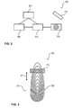
- FIG. 2 a schematic representation of an inductive sensor 100 is shown, this schematic general structure for both the inductive sensor 100 of the cashbox after FIG. 1 as well as for the other inductive sensors described above.
- the inductive sensor 100 has a coil arrangement 110, via which an alternating magnetic field is generated. Further, the inductive sensor 100 has a conductive element 112 which is positionally variable relative to the coil assembly 110. Depending on the position of the conductive element 112 relative to the coil arrangement 110, this influences the alternating magnetic field differently. This change is detected by a sensor circuit 114 of the inductive sensor 100 and evaluated by means of a control unit 116 of the inductive sensor 100.
- the inductive sensor may comprise a power supply unit 118, for example a battery or an accumulator.
- the conductive element 112 is in particular formed as a conductive strip, preferably a metallic strip.
- the coil arrangement 110 can comprise both one and a plurality of coils, and is designed in particular as a circuit board with a correspondingly printed coil.
- the sensor circuit 114 is designed in particular in the form of an integrated circuit.
- the control unit 116 is preferably a microcontroller which is arranged on the same board as the integrated circuit of the sensor circuit 114. Overall, this results in a particularly compact inductive sensor 100, which is therefore often referred to as an inductive miniature sensor.
- the inductive sensor 100 in the cash box 10 takes up only little space and can be integrated into existing cash boxes 10 without retrofitting as a retrofit solution.
- the inductive sensor 100 has a non-visible conductive strip which is arranged on the side of the pressure unit 18 facing the bottom 20 of the cash box 10.
- the coil assembly 110 is formed as a board which extends in the direction of movement P1 of the pressure unit 18 over the entire width of the receiving area. In an alternative embodiment, the coil assembly 110 may not extend across the entire width. In this case, the coil arrangement 110 is embodied such that the conductive element 112, depending on its position and thus dependent on the position of the pressure unit 18 relative to the coil arrangement 110, influences the alternating magnetic field generated by the coil arrangement 110 differently, this influencing then being effected via the sensor circuit 114 and the microcontroller 116 is detected and depending on the determined change the position of the pressure unit 18 is determined.
- the coil arrangement 110 is designed in such a way that the magnetic alternating field generated with it in the direction of movement P1 is positionally different, so that the conductive element 112 influences the magnetic alternating field differently.
- FIG. 3 is a section of an inductive sensor 100 according to the cashbox 10 and FIG. 1 used in a first embodiment shown in which the coil assembly 110 includes only a single coil 120 which is formed such that the dependence of the position with respect to the direction of movement P1, the distance between the turns and thus the number of turns in the region of the conductive element 112 varies.
- the change in the inductance as a function of the number of turns of the coil in the region of the electrically conductive element 112 is utilized. As in FIG. 3 As can be clearly seen, depending on the position, the electrically conductive element 112 "covers" a different number of turns of the coil 120 and thus influences the magnetic field differently.
- FIG. 2 shows a section of an inductive sensor 102 according to a second embodiment, which may also be used as an alternative to the coil circuit 110 according to the first embodiment in a movable conductive element and a stationary coil arrangement 110.
- the inductive sensor 102 according to the second embodiment differs from the inductive sensor 100 according to the first embodiment in that the coil assembly 110 includes four coils 122 to 128, which are arranged one after the other as viewed in the direction of movement P1 and connected in series.
- the coils 122 to 128 have a different number of turns, so too
- the position of the electrically conductive element 112 relative to the coil assembly 110 can be easily determined by the inductive sensor 102.
- the pressure unit 18 is moved in the direction of the double arrow P1 through the receiving area 14 of the cashbox 10 during operation of the cashbox.
- the conductive strip 112 arranged on the underside of the pressure unit 18 is moved via the coil arrangement 110 to a predetermined distance.
- the resolution and accuracy of the position determination can be determined by the specific structure of the coil assembly 110 as well as the size and the material of the conductive strip 112.
- the accuracy of such an inductive sensor 110 is so high that the distance between the coil assembly 110 and the conductive strip 112 may be several millimeters.
- FIG. 5 is a schematic representation of a section of an inductive sensor 104 according to a third embodiment shown.
- the coil assembly 110 is fixedly arranged on the pressure unit 18.
- a conductive strip 112 is arranged, which has a triangular shape, so that the width of the conductive strip 112 as seen in the direction of movement P1 changes.
- the conductive strip 112 may be formed in particular as a copper layer on a printed circuit board.
- FIG. 6 is a schematic perspective view of a cashbox 30 according to a second embodiment shown, wherein many elements of the cashbox 30 are not shown.
- the cash box 30 has two sobeskyr 32, 34, by means of which the width of the receiving area 14 can be adjusted and adjusted in particular to the width of the recorded notes of value. Accordingly, the sobeskyr 32, 34 are arranged to move in the direction of the double arrow P2.
- two inductive sensors 106 are provided, wherein the sensors 106 are formed analogous to the inductive sensor 100 according to the first embodiment.
- the inductive sensors 102 each have a non-visible conductive strip on the underside of the respective side limiter 32, 34, which is moved with the side limiter 32, 34 relative to a coil assembly 110. Not shown sensor circuits 114 may turn the position of the Sobeskyr 32, 34 are easily determined.
- sensors according to the in connection with FIG. 4 described second embodiment or inductive sensors 104 according to the in connection with FIG. 5 described third embodiment can be used.
- the cash box may also have both a pressure unit 18 and side limiters 32, 34, whose position can be determined in each case via an inductive sensor 100 to 106.
- the positions of a plurality of movable elements 18, 32, 34 can also be determined via an inductive sensor by the use of a plurality of correspondingly more complex coil arrangements 110.
- FIG. 7 is a schematic representation of a section of the inductive sensor 108 according to a fourth embodiment shown.
- the inductive sensor 108 has two coil arrangements 110, 130, which are rotated through 180 ° are arranged to each other and over which the conductive strip 112 is moved together.
- two separate coil arrangements 110, 130 By using two separate coil arrangements 110, 130, a differential measurement is made possible, which enables the compensation of manufacturing tolerances and thus achieves an even more accurate measurement result.
- two or more than two conductive strips 112 may also be used.
- FIG. 8 1 is a schematic illustration of a section of an inductive sensor 109 according to a fifth embodiment, wherein in this fifth embodiment two coil arrangements 110, 130 are provided, which are arranged on the movable elements 18, 32, 34 and relative to two conductive strips 112, 132 to be moved. These two strips 112, 132 are each triangular, but arranged rotated by 180 ° to each other. This also makes a differential measurement possible again, which provides high accuracies even with manufacturing tolerances.
- the inductive sensors 108, 109 according to the FIGS. 7 and 8 may alternatively to the other inductive sensors 100 to 106 in the cash boxes 10, 30 according to the FIGS. 1 and 6 be used.
Landscapes
- Physics & Mathematics (AREA)
- General Physics & Mathematics (AREA)
- Geophysics And Detection Of Objects (AREA)
- Measurement Of Length, Angles, Or The Like Using Electric Or Magnetic Means (AREA)
Priority Applications (1)
| Application Number | Priority Date | Filing Date | Title |
|---|---|---|---|
| EP14176710.3A EP2966627B1 (fr) | 2014-07-11 | 2014-07-11 | Coffre doté de capteur inductif destiné à déterminer la position d'éléments mobiles |
Applications Claiming Priority (1)
| Application Number | Priority Date | Filing Date | Title |
|---|---|---|---|
| EP14176710.3A EP2966627B1 (fr) | 2014-07-11 | 2014-07-11 | Coffre doté de capteur inductif destiné à déterminer la position d'éléments mobiles |
Publications (2)
| Publication Number | Publication Date |
|---|---|
| EP2966627A1 true EP2966627A1 (fr) | 2016-01-13 |
| EP2966627B1 EP2966627B1 (fr) | 2022-06-01 |
Family
ID=51162601
Family Applications (1)
| Application Number | Title | Priority Date | Filing Date |
|---|---|---|---|
| EP14176710.3A Active EP2966627B1 (fr) | 2014-07-11 | 2014-07-11 | Coffre doté de capteur inductif destiné à déterminer la position d'éléments mobiles |
Country Status (1)
| Country | Link |
|---|---|
| EP (1) | EP2966627B1 (fr) |
Cited By (3)
| Publication number | Priority date | Publication date | Assignee | Title |
|---|---|---|---|---|
| EP3780392A1 (fr) * | 2019-08-16 | 2021-02-17 | Illinois Tool Works NC. | Capteur de position inductif avec fonction de commutation |
| EP3799990A1 (fr) * | 2019-08-16 | 2021-04-07 | Illinois Tool Works Inc. | Capteur de position inductif, et contrôleur activé mécaniquement comportants une fonction de commutation, et dispositif de contrôle de soudage avec de tels capteur/contrôleur |
| EP3859283A1 (fr) * | 2020-01-30 | 2021-08-04 | Illinois Tool Works INC. | Capteur de position inductif comportant une fonction de commutation |
Citations (9)
| Publication number | Priority date | Publication date | Assignee | Title |
|---|---|---|---|---|
| US4816652A (en) * | 1987-09-22 | 1989-03-28 | Ncr Corporation | Currency cassette and cash dispensing system including such cassette |
| DE19839977A1 (de) | 1998-09-02 | 2000-03-09 | Siemens Nixdorf Inf Syst | Geldkassettenanordnung |
| DE20009335U1 (de) * | 2000-05-24 | 2001-10-04 | Gebhard Balluff Fabrik feinmechanischer Erzeugnisse GmbH & Co, 73765 Neuhausen | Wegmeßsystem |
| DE10193514T1 (de) | 2000-08-23 | 2003-07-17 | Nippon Conlux Co Ltd | Münzsortiervorrichtung |
| DE69814924T2 (de) | 1997-12-31 | 2004-02-05 | Fluiditi Ltd. | Sicherheitssystem |
| DE69725011T2 (de) | 1996-07-19 | 2004-07-08 | Mars, Inc. | Sicherheitsberechtigungsschein für elektronische sperrvorrichtung in verkaufsautomaten |
| DE102008012046A1 (de) * | 2008-03-01 | 2009-09-03 | Wincor Nixdorf International Gmbh | Vorrichtung zur Füllstandmessung in Wertbehältern |
| DE102009006810A1 (de) | 2009-01-30 | 2010-08-05 | Wincor Nixdorf International Gmbh | Vorrichtung und Verfahren zur Einzahlung und/oder Auszahlung zumindest von Banknoten mit einem ersten Nennwert und Banknoten mit einem zweiten Nennwert |
| DE202011051121U1 (de) | 2010-12-28 | 2011-11-09 | Novotech Elektronik Ges. M.B.H. | Vorrichtung zur Münzerkennung |
-
2014
- 2014-07-11 EP EP14176710.3A patent/EP2966627B1/fr active Active
Patent Citations (9)
| Publication number | Priority date | Publication date | Assignee | Title |
|---|---|---|---|---|
| US4816652A (en) * | 1987-09-22 | 1989-03-28 | Ncr Corporation | Currency cassette and cash dispensing system including such cassette |
| DE69725011T2 (de) | 1996-07-19 | 2004-07-08 | Mars, Inc. | Sicherheitsberechtigungsschein für elektronische sperrvorrichtung in verkaufsautomaten |
| DE69814924T2 (de) | 1997-12-31 | 2004-02-05 | Fluiditi Ltd. | Sicherheitssystem |
| DE19839977A1 (de) | 1998-09-02 | 2000-03-09 | Siemens Nixdorf Inf Syst | Geldkassettenanordnung |
| DE20009335U1 (de) * | 2000-05-24 | 2001-10-04 | Gebhard Balluff Fabrik feinmechanischer Erzeugnisse GmbH & Co, 73765 Neuhausen | Wegmeßsystem |
| DE10193514T1 (de) | 2000-08-23 | 2003-07-17 | Nippon Conlux Co Ltd | Münzsortiervorrichtung |
| DE102008012046A1 (de) * | 2008-03-01 | 2009-09-03 | Wincor Nixdorf International Gmbh | Vorrichtung zur Füllstandmessung in Wertbehältern |
| DE102009006810A1 (de) | 2009-01-30 | 2010-08-05 | Wincor Nixdorf International Gmbh | Vorrichtung und Verfahren zur Einzahlung und/oder Auszahlung zumindest von Banknoten mit einem ersten Nennwert und Banknoten mit einem zweiten Nennwert |
| DE202011051121U1 (de) | 2010-12-28 | 2011-11-09 | Novotech Elektronik Ges. M.B.H. | Vorrichtung zur Münzerkennung |
Cited By (5)
| Publication number | Priority date | Publication date | Assignee | Title |
|---|---|---|---|---|
| EP3780392A1 (fr) * | 2019-08-16 | 2021-02-17 | Illinois Tool Works NC. | Capteur de position inductif avec fonction de commutation |
| CN112393673A (zh) * | 2019-08-16 | 2021-02-23 | 伊利诺斯工具制品有限公司 | 具有开关功能的感应式位置传感器 |
| EP3799990A1 (fr) * | 2019-08-16 | 2021-04-07 | Illinois Tool Works Inc. | Capteur de position inductif, et contrôleur activé mécaniquement comportants une fonction de commutation, et dispositif de contrôle de soudage avec de tels capteur/contrôleur |
| EP3859283A1 (fr) * | 2020-01-30 | 2021-08-04 | Illinois Tool Works INC. | Capteur de position inductif comportant une fonction de commutation |
| US11305368B2 (en) | 2020-01-30 | 2022-04-19 | Illinois Tool Works Inc. | Inductive position sensor with switch function |
Also Published As
| Publication number | Publication date |
|---|---|
| EP2966627B1 (fr) | 2022-06-01 |
Similar Documents
| Publication | Publication Date | Title |
|---|---|---|
| EP1688709B1 (fr) | Procédé de détermination d'une position le long d'un trajet d'un élément d'actionnement d'une unité de détection inductive | |
| EP2137499B1 (fr) | Procédé et système de détecteur pour la détermination de la position et/ou de la modification de la position d'un objet mesuré par rapport à un détecteur | |
| EP1877724B1 (fr) | Dispositif de controle d'epaisseurs et de variations d'epaisseurs | |
| DE102010056271A1 (de) | Sensoranordnung zur Erfassung sowohl der Axial- als auch der Drehstellung einer in Längsrichtung verschieblichen und drehbaren Welle | |
| DE102015225221A1 (de) | Linearwegsensor | |
| EP3458812B1 (fr) | Capteur de déplacement linéaire autorisant le basculement | |
| EP1884749B1 (fr) | Dispositif de mesure de position ou de mesure angulaire inductif | |
| EP2966627B1 (fr) | Coffre doté de capteur inductif destiné à déterminer la position d'éléments mobiles | |
| DE102012200244A1 (de) | Sensoranordnung | |
| EP0936444B1 (fr) | Dispositif de détection sans contact de la position d'un objet, en particulier d'un arbre de commande d'une boîte de vitesse d'un véhicule | |
| DE102013226203A1 (de) | Offsetkompensierte Positionsmessvorrichtung | |
| WO2009024479A1 (fr) | Cellule de mesure de conductivité à induction | |
| WO2002063572A2 (fr) | Dispositif de reception de billets de banque | |
| EP2376865A1 (fr) | Dispositif pour déterminer une épaisseur ou une variation d'épaisseur d'un objet plat | |
| DE102007033745A1 (de) | Induktive Drehzahlerkennung | |
| DE102007011952B4 (de) | Bewegungsmessvorrichtung, insbesondere Drehwinkelgeber | |
| WO2018108519A1 (fr) | Conducteur de flux pour un dispositif détecteur de couple, procédé de fabrication d'un conducteur de flux pour un dispositif détecteur de couple et dispositif détecteur de couple | |
| DE20120658U1 (de) | Induktive Positionserkennungsvorrichtung | |
| DE102007001821A1 (de) | Induktiver Näherungsschalter | |
| DE102008064544B4 (de) | Positions-/Wegmesssystem und Verfahren zur Bestimmung der Position eines Gebers | |
| DE102007033751A1 (de) | Anordnung eines Spulenpaares in einem örtlichen Messbereich | |
| DE60034471T2 (de) | Elektronisches lenksäulenmodul | |
| WO1997038400A1 (fr) | Dispositif pour le controle de l'authenticite de pieces de monnaie, jetons ou autres objets metalliques plats | |
| EP1306649A1 (fr) | Capteur inductif pour la détermination d'une position angulaire ou d'un déplacement | |
| DE3511782C2 (de) | Kolbenstellungsgeber |
Legal Events
| Date | Code | Title | Description |
|---|---|---|---|
| PUAI | Public reference made under article 153(3) epc to a published international application that has entered the european phase |
Free format text: ORIGINAL CODE: 0009012 |
|
| AK | Designated contracting states |
Kind code of ref document: A1 Designated state(s): AL AT BE BG CH CY CZ DE DK EE ES FI FR GB GR HR HU IE IS IT LI LT LU LV MC MK MT NL NO PL PT RO RS SE SI SK SM TR |
|
| AX | Request for extension of the european patent |
Extension state: BA ME |
|
| 17P | Request for examination filed |
Effective date: 20160711 |
|
| RBV | Designated contracting states (corrected) |
Designated state(s): AL AT BE BG CH CY CZ DE DK EE ES FI FR GB GR HR HU IE IS IT LI LT LU LV MC MK MT NL NO PL PT RO RS SE SI SK SM TR |
|
| STAA | Information on the status of an ep patent application or granted ep patent |
Free format text: STATUS: EXAMINATION IS IN PROGRESS |
|
| 17Q | First examination report despatched |
Effective date: 20210616 |
|
| RIC1 | Information provided on ipc code assigned before grant |
Ipc: G07D 11/23 20190101ALI20211025BHEP Ipc: G07D 11/00 20190101AFI20211025BHEP |
|
| GRAP | Despatch of communication of intention to grant a patent |
Free format text: ORIGINAL CODE: EPIDOSNIGR1 |
|
| STAA | Information on the status of an ep patent application or granted ep patent |
Free format text: STATUS: GRANT OF PATENT IS INTENDED |
|
| INTG | Intention to grant announced |
Effective date: 20211210 |
|
| GRAS | Grant fee paid |
Free format text: ORIGINAL CODE: EPIDOSNIGR3 |
|
| GRAA | (expected) grant |
Free format text: ORIGINAL CODE: 0009210 |
|
| STAA | Information on the status of an ep patent application or granted ep patent |
Free format text: STATUS: THE PATENT HAS BEEN GRANTED |
|
| AK | Designated contracting states |
Kind code of ref document: B1 Designated state(s): AL AT BE BG CH CY CZ DE DK EE ES FI FR GB GR HR HU IE IS IT LI LT LU LV MC MK MT NL NO PL PT RO RS SE SI SK SM TR |
|
| REG | Reference to a national code |
Ref country code: GB Ref legal event code: FG4D Free format text: NOT ENGLISH |
|
| REG | Reference to a national code |
Ref country code: AT Ref legal event code: REF Ref document number: 1495923 Country of ref document: AT Kind code of ref document: T Effective date: 20220615 Ref country code: CH Ref legal event code: EP Ref country code: DE Ref legal event code: R096 Ref document number: 502014016266 Country of ref document: DE |
|
| REG | Reference to a national code |
Ref country code: IE Ref legal event code: FG4D Free format text: LANGUAGE OF EP DOCUMENT: GERMAN |
|
| REG | Reference to a national code |
Ref country code: FR Ref legal event code: PLFP Year of fee payment: 9 |
|
| REG | Reference to a national code |
Ref country code: LT Ref legal event code: MG9D |
|
| REG | Reference to a national code |
Ref country code: NL Ref legal event code: MP Effective date: 20220601 |
|
| PG25 | Lapsed in a contracting state [announced via postgrant information from national office to epo] |
Ref country code: SE Free format text: LAPSE BECAUSE OF FAILURE TO SUBMIT A TRANSLATION OF THE DESCRIPTION OR TO PAY THE FEE WITHIN THE PRESCRIBED TIME-LIMIT Effective date: 20220601 Ref country code: NO Free format text: LAPSE BECAUSE OF FAILURE TO SUBMIT A TRANSLATION OF THE DESCRIPTION OR TO PAY THE FEE WITHIN THE PRESCRIBED TIME-LIMIT Effective date: 20220901 Ref country code: LT Free format text: LAPSE BECAUSE OF FAILURE TO SUBMIT A TRANSLATION OF THE DESCRIPTION OR TO PAY THE FEE WITHIN THE PRESCRIBED TIME-LIMIT Effective date: 20220601 Ref country code: HR Free format text: LAPSE BECAUSE OF FAILURE TO SUBMIT A TRANSLATION OF THE DESCRIPTION OR TO PAY THE FEE WITHIN THE PRESCRIBED TIME-LIMIT Effective date: 20220601 Ref country code: GR Free format text: LAPSE BECAUSE OF FAILURE TO SUBMIT A TRANSLATION OF THE DESCRIPTION OR TO PAY THE FEE WITHIN THE PRESCRIBED TIME-LIMIT Effective date: 20220902 Ref country code: FI Free format text: LAPSE BECAUSE OF FAILURE TO SUBMIT A TRANSLATION OF THE DESCRIPTION OR TO PAY THE FEE WITHIN THE PRESCRIBED TIME-LIMIT Effective date: 20220601 Ref country code: ES Free format text: LAPSE BECAUSE OF FAILURE TO SUBMIT A TRANSLATION OF THE DESCRIPTION OR TO PAY THE FEE WITHIN THE PRESCRIBED TIME-LIMIT Effective date: 20220601 Ref country code: BG Free format text: LAPSE BECAUSE OF FAILURE TO SUBMIT A TRANSLATION OF THE DESCRIPTION OR TO PAY THE FEE WITHIN THE PRESCRIBED TIME-LIMIT Effective date: 20220901 |
|
| PG25 | Lapsed in a contracting state [announced via postgrant information from national office to epo] |
Ref country code: RS Free format text: LAPSE BECAUSE OF FAILURE TO SUBMIT A TRANSLATION OF THE DESCRIPTION OR TO PAY THE FEE WITHIN THE PRESCRIBED TIME-LIMIT Effective date: 20220601 Ref country code: PL Free format text: LAPSE BECAUSE OF FAILURE TO SUBMIT A TRANSLATION OF THE DESCRIPTION OR TO PAY THE FEE WITHIN THE PRESCRIBED TIME-LIMIT Effective date: 20220601 Ref country code: LV Free format text: LAPSE BECAUSE OF FAILURE TO SUBMIT A TRANSLATION OF THE DESCRIPTION OR TO PAY THE FEE WITHIN THE PRESCRIBED TIME-LIMIT Effective date: 20220601 |
|
| PG25 | Lapsed in a contracting state [announced via postgrant information from national office to epo] |
Ref country code: NL Free format text: LAPSE BECAUSE OF FAILURE TO SUBMIT A TRANSLATION OF THE DESCRIPTION OR TO PAY THE FEE WITHIN THE PRESCRIBED TIME-LIMIT Effective date: 20220601 |
|
| PG25 | Lapsed in a contracting state [announced via postgrant information from national office to epo] |
Ref country code: SM Free format text: LAPSE BECAUSE OF FAILURE TO SUBMIT A TRANSLATION OF THE DESCRIPTION OR TO PAY THE FEE WITHIN THE PRESCRIBED TIME-LIMIT Effective date: 20220601 Ref country code: SK Free format text: LAPSE BECAUSE OF FAILURE TO SUBMIT A TRANSLATION OF THE DESCRIPTION OR TO PAY THE FEE WITHIN THE PRESCRIBED TIME-LIMIT Effective date: 20220601 Ref country code: RO Free format text: LAPSE BECAUSE OF FAILURE TO SUBMIT A TRANSLATION OF THE DESCRIPTION OR TO PAY THE FEE WITHIN THE PRESCRIBED TIME-LIMIT Effective date: 20220601 Ref country code: PT Free format text: LAPSE BECAUSE OF FAILURE TO SUBMIT A TRANSLATION OF THE DESCRIPTION OR TO PAY THE FEE WITHIN THE PRESCRIBED TIME-LIMIT Effective date: 20221003 Ref country code: EE Free format text: LAPSE BECAUSE OF FAILURE TO SUBMIT A TRANSLATION OF THE DESCRIPTION OR TO PAY THE FEE WITHIN THE PRESCRIBED TIME-LIMIT Effective date: 20220601 Ref country code: CZ Free format text: LAPSE BECAUSE OF FAILURE TO SUBMIT A TRANSLATION OF THE DESCRIPTION OR TO PAY THE FEE WITHIN THE PRESCRIBED TIME-LIMIT Effective date: 20220601 |
|
| PG25 | Lapsed in a contracting state [announced via postgrant information from national office to epo] |
Ref country code: MC Free format text: LAPSE BECAUSE OF FAILURE TO SUBMIT A TRANSLATION OF THE DESCRIPTION OR TO PAY THE FEE WITHIN THE PRESCRIBED TIME-LIMIT Effective date: 20220601 Ref country code: IS Free format text: LAPSE BECAUSE OF FAILURE TO SUBMIT A TRANSLATION OF THE DESCRIPTION OR TO PAY THE FEE WITHIN THE PRESCRIBED TIME-LIMIT Effective date: 20221001 |
|
| REG | Reference to a national code |
Ref country code: CH Ref legal event code: PL |
|
| REG | Reference to a national code |
Ref country code: DE Ref legal event code: R097 Ref document number: 502014016266 Country of ref document: DE |
|
| REG | Reference to a national code |
Ref country code: BE Ref legal event code: MM Effective date: 20220731 |
|
| PG25 | Lapsed in a contracting state [announced via postgrant information from national office to epo] |
Ref country code: AL Free format text: LAPSE BECAUSE OF FAILURE TO SUBMIT A TRANSLATION OF THE DESCRIPTION OR TO PAY THE FEE WITHIN THE PRESCRIBED TIME-LIMIT Effective date: 20220601 |
|
| PLBE | No opposition filed within time limit |
Free format text: ORIGINAL CODE: 0009261 |
|
| STAA | Information on the status of an ep patent application or granted ep patent |
Free format text: STATUS: NO OPPOSITION FILED WITHIN TIME LIMIT |
|
| REG | Reference to a national code |
Ref country code: GB Ref legal event code: 732E Free format text: REGISTERED BETWEEN 20230323 AND 20230329 |
|
| PG25 | Lapsed in a contracting state [announced via postgrant information from national office to epo] |
Ref country code: LU Free format text: LAPSE BECAUSE OF NON-PAYMENT OF DUE FEES Effective date: 20220711 Ref country code: LI Free format text: LAPSE BECAUSE OF NON-PAYMENT OF DUE FEES Effective date: 20220731 Ref country code: DK Free format text: LAPSE BECAUSE OF FAILURE TO SUBMIT A TRANSLATION OF THE DESCRIPTION OR TO PAY THE FEE WITHIN THE PRESCRIBED TIME-LIMIT Effective date: 20220601 Ref country code: CH Free format text: LAPSE BECAUSE OF NON-PAYMENT OF DUE FEES Effective date: 20220731 |
|
| 26N | No opposition filed |
Effective date: 20230302 |
|
| PG25 | Lapsed in a contracting state [announced via postgrant information from national office to epo] |
Ref country code: SI Free format text: LAPSE BECAUSE OF FAILURE TO SUBMIT A TRANSLATION OF THE DESCRIPTION OR TO PAY THE FEE WITHIN THE PRESCRIBED TIME-LIMIT Effective date: 20220601 Ref country code: BE Free format text: LAPSE BECAUSE OF NON-PAYMENT OF DUE FEES Effective date: 20220731 |
|
| REG | Reference to a national code |
Ref country code: GB Ref legal event code: 732E Free format text: REGISTERED BETWEEN 20230525 AND 20230601 |
|
| PG25 | Lapsed in a contracting state [announced via postgrant information from national office to epo] |
Ref country code: IE Free format text: LAPSE BECAUSE OF NON-PAYMENT OF DUE FEES Effective date: 20220711 |
|
| REG | Reference to a national code |
Ref country code: DE Ref legal event code: R081 Ref document number: 502014016266 Country of ref document: DE Owner name: DIEBOLD NIXDORF SYSTEMS GMBH, DE Free format text: FORMER OWNER: WINCOR NIXDORF INTERNATIONAL GMBH, 33106 PADERBORN, DE Ref country code: AT Ref legal event code: MM01 Ref document number: 1495923 Country of ref document: AT Kind code of ref document: T Effective date: 20220711 |
|
| PG25 | Lapsed in a contracting state [announced via postgrant information from national office to epo] |
Ref country code: AT Free format text: LAPSE BECAUSE OF NON-PAYMENT OF DUE FEES Effective date: 20220711 |
|
| PG25 | Lapsed in a contracting state [announced via postgrant information from national office to epo] |
Ref country code: IT Free format text: LAPSE BECAUSE OF FAILURE TO SUBMIT A TRANSLATION OF THE DESCRIPTION OR TO PAY THE FEE WITHIN THE PRESCRIBED TIME-LIMIT Effective date: 20220601 |
|
| PG25 | Lapsed in a contracting state [announced via postgrant information from national office to epo] |
Ref country code: HU Free format text: LAPSE BECAUSE OF FAILURE TO SUBMIT A TRANSLATION OF THE DESCRIPTION OR TO PAY THE FEE WITHIN THE PRESCRIBED TIME-LIMIT; INVALID AB INITIO Effective date: 20140711 |
|
| PG25 | Lapsed in a contracting state [announced via postgrant information from national office to epo] |
Ref country code: MK Free format text: LAPSE BECAUSE OF FAILURE TO SUBMIT A TRANSLATION OF THE DESCRIPTION OR TO PAY THE FEE WITHIN THE PRESCRIBED TIME-LIMIT Effective date: 20220601 Ref country code: CY Free format text: LAPSE BECAUSE OF FAILURE TO SUBMIT A TRANSLATION OF THE DESCRIPTION OR TO PAY THE FEE WITHIN THE PRESCRIBED TIME-LIMIT Effective date: 20220601 |
|
| PG25 | Lapsed in a contracting state [announced via postgrant information from national office to epo] |
Ref country code: TR Free format text: LAPSE BECAUSE OF FAILURE TO SUBMIT A TRANSLATION OF THE DESCRIPTION OR TO PAY THE FEE WITHIN THE PRESCRIBED TIME-LIMIT Effective date: 20220601 |
|
| PG25 | Lapsed in a contracting state [announced via postgrant information from national office to epo] |
Ref country code: MT Free format text: LAPSE BECAUSE OF FAILURE TO SUBMIT A TRANSLATION OF THE DESCRIPTION OR TO PAY THE FEE WITHIN THE PRESCRIBED TIME-LIMIT Effective date: 20220601 |
|
| PG25 | Lapsed in a contracting state [announced via postgrant information from national office to epo] |
Ref country code: BG Free format text: LAPSE BECAUSE OF FAILURE TO SUBMIT A TRANSLATION OF THE DESCRIPTION OR TO PAY THE FEE WITHIN THE PRESCRIBED TIME-LIMIT Effective date: 20220601 |
|
| PG25 | Lapsed in a contracting state [announced via postgrant information from national office to epo] |
Ref country code: BG Free format text: LAPSE BECAUSE OF FAILURE TO SUBMIT A TRANSLATION OF THE DESCRIPTION OR TO PAY THE FEE WITHIN THE PRESCRIBED TIME-LIMIT Effective date: 20220601 |
|
| PGFP | Annual fee paid to national office [announced via postgrant information from national office to epo] |
Ref country code: GB Payment date: 20250619 Year of fee payment: 12 |
|
| PGFP | Annual fee paid to national office [announced via postgrant information from national office to epo] |
Ref country code: FR Payment date: 20250619 Year of fee payment: 12 |
|
| PGFP | Annual fee paid to national office [announced via postgrant information from national office to epo] |
Ref country code: DE Payment date: 20250620 Year of fee payment: 12 |