EP2966656A1 - Spulenarchitektur für induktivsensoren - Google Patents
Spulenarchitektur für induktivsensoren Download PDFInfo
- Publication number
- EP2966656A1 EP2966656A1 EP15174543.7A EP15174543A EP2966656A1 EP 2966656 A1 EP2966656 A1 EP 2966656A1 EP 15174543 A EP15174543 A EP 15174543A EP 2966656 A1 EP2966656 A1 EP 2966656A1
- Authority
- EP
- European Patent Office
- Prior art keywords
- coil
- receiver
- transmitter coil
- receiver coil
- transmitter
- Prior art date
- Legal status (The legal status is an assumption and is not a legal conclusion. Google has not performed a legal analysis and makes no representation as to the accuracy of the status listed.)
- Granted
Links
Images




Classifications
-
- G—PHYSICS
- G01—MEASURING; TESTING
- G01R—MEASURING ELECTRIC VARIABLES; MEASURING MAGNETIC VARIABLES
- G01R27/00—Arrangements for measuring resistance, reactance, impedance, or electric characteristics derived therefrom
- G01R27/02—Measuring real or complex resistance, reactance, impedance, or other two-pole characteristics derived therefrom, e.g. time constant
- G01R27/26—Measuring inductance or capacitance; Measuring quality factor, e.g. by using the resonance method; Measuring loss factor; Measuring dielectric constants ; Measuring impedance or related variables
- G01R27/2611—Measuring inductance
-
- H—ELECTRICITY
- H01—ELECTRIC ELEMENTS
- H01F—MAGNETS; INDUCTANCES; TRANSFORMERS; SELECTION OF MATERIALS FOR THEIR MAGNETIC PROPERTIES
- H01F5/00—Coils
- H01F5/02—Coils wound on non-magnetic supports, e.g. formers
-
- G—PHYSICS
- G01—MEASURING; TESTING
- G01V—GEOPHYSICS; GRAVITATIONAL MEASUREMENTS; DETECTING MASSES OR OBJECTS; TAGS
- G01V3/00—Electric or magnetic prospecting or detecting; Measuring magnetic field characteristics of the earth, e.g. declination, deviation
- G01V3/08—Electric or magnetic prospecting or detecting; Measuring magnetic field characteristics of the earth, e.g. declination, deviation operating with magnetic or electric fields produced or modified by objects or geological structures or by detecting devices
- G01V3/10—Electric or magnetic prospecting or detecting; Measuring magnetic field characteristics of the earth, e.g. declination, deviation operating with magnetic or electric fields produced or modified by objects or geological structures or by detecting devices using induction coils
- G01V3/104—Electric or magnetic prospecting or detecting; Measuring magnetic field characteristics of the earth, e.g. declination, deviation operating with magnetic or electric fields produced or modified by objects or geological structures or by detecting devices using induction coils using several coupled or uncoupled coils
- G01V3/105—Electric or magnetic prospecting or detecting; Measuring magnetic field characteristics of the earth, e.g. declination, deviation operating with magnetic or electric fields produced or modified by objects or geological structures or by detecting devices using induction coils using several coupled or uncoupled coils forming directly coupled primary and secondary coils or loops
- G01V3/107—Electric or magnetic prospecting or detecting; Measuring magnetic field characteristics of the earth, e.g. declination, deviation operating with magnetic or electric fields produced or modified by objects or geological structures or by detecting devices using induction coils using several coupled or uncoupled coils forming directly coupled primary and secondary coils or loops using compensating coil or loop arrangements
-
- H—ELECTRICITY
- H01—ELECTRIC ELEMENTS
- H01F—MAGNETS; INDUCTANCES; TRANSFORMERS; SELECTION OF MATERIALS FOR THEIR MAGNETIC PROPERTIES
- H01F21/00—Variable inductances or transformers of the signal type
- H01F21/02—Variable inductances or transformers of the signal type continuously variable, e.g. variometers
-
- H—ELECTRICITY
- H01—ELECTRIC ELEMENTS
- H01F—MAGNETS; INDUCTANCES; TRANSFORMERS; SELECTION OF MATERIALS FOR THEIR MAGNETIC PROPERTIES
- H01F27/00—Details of transformers or inductances, in general
- H01F27/28—Coils; Windings; Conductive connections
- H01F27/2823—Wires
-
- H—ELECTRICITY
- H01—ELECTRIC ELEMENTS
- H01F—MAGNETS; INDUCTANCES; TRANSFORMERS; SELECTION OF MATERIALS FOR THEIR MAGNETIC PROPERTIES
- H01F27/00—Details of transformers or inductances, in general
- H01F27/28—Coils; Windings; Conductive connections
- H01F27/30—Fastening or clamping coils, windings, or parts thereof together; Fastening or mounting coils or windings on core, casing, or other support
- H01F27/306—Fastening or mounting coils or windings on core, casing or other support
-
- H—ELECTRICITY
- H01—ELECTRIC ELEMENTS
- H01F—MAGNETS; INDUCTANCES; TRANSFORMERS; SELECTION OF MATERIALS FOR THEIR MAGNETIC PROPERTIES
- H01F27/00—Details of transformers or inductances, in general
- H01F27/28—Coils; Windings; Conductive connections
- H01F27/32—Insulating of coils, windings, or parts thereof
- H01F27/324—Insulation between coil and core, between different winding sections, around the coil; Other insulation structures
- H01F27/325—Coil bobbins
-
- H—ELECTRICITY
- H01—ELECTRIC ELEMENTS
- H01F—MAGNETS; INDUCTANCES; TRANSFORMERS; SELECTION OF MATERIALS FOR THEIR MAGNETIC PROPERTIES
- H01F27/00—Details of transformers or inductances, in general
- H01F27/40—Structural association with built-in electric component, e.g. fuse
- H01F27/402—Association of measuring or protective means
-
- H—ELECTRICITY
- H01—ELECTRIC ELEMENTS
- H01F—MAGNETS; INDUCTANCES; TRANSFORMERS; SELECTION OF MATERIALS FOR THEIR MAGNETIC PROPERTIES
- H01F41/00—Apparatus or processes specially adapted for manufacturing or assembling magnets, inductances or transformers; Apparatus or processes specially adapted for manufacturing materials characterised by their magnetic properties
- H01F41/02—Apparatus or processes specially adapted for manufacturing or assembling magnets, inductances or transformers; Apparatus or processes specially adapted for manufacturing materials characterised by their magnetic properties for manufacturing cores, coils, or magnets
- H01F41/04—Apparatus or processes specially adapted for manufacturing or assembling magnets, inductances or transformers; Apparatus or processes specially adapted for manufacturing materials characterised by their magnetic properties for manufacturing cores, coils, or magnets for manufacturing coils
- H01F41/06—Coil winding
-
- H—ELECTRICITY
- H01—ELECTRIC ELEMENTS
- H01F—MAGNETS; INDUCTANCES; TRANSFORMERS; SELECTION OF MATERIALS FOR THEIR MAGNETIC PROPERTIES
- H01F5/00—Coils
- H01F5/02—Coils wound on non-magnetic supports, e.g. formers
- H01F2005/022—Coils wound on non-magnetic supports, e.g. formers wound on formers with several winding chambers separated by flanges, e.g. for high voltage applications
Definitions
- the subject matter disclosed herein relates generally to inductive sensors, and, more particularly, to an inductive sensor coil architecture that reduces sensitivity to environmental variables and reduces the size of sensor components.
- an assembly for supporting coils of an inductive sensor comprising a transmitter coil and at least one receiver coil, wherein at least a portion of the transmitter coil is co-located with at least a portion of a receiver coil of the at least one receiver coil.
- a method for arranging inductive coils of an inductive sensor comprising locating at least a first portion of a transmitter coil of the inductive sensor on a section of a winding structure, and locating at least a second portion of a receiver coil of the inductive sensor on the section of the winding structure together with at least the first portion of the transmitter coil.
- an inductive sensor comprising a transmitter coil comprising a first number of turns, and a receiver coil comprising a second number of turns, wherein at least a subset of the first number of turns of the transmitter coil are wound together with at least a subset of the second number of turns of the receiver coil.
- the terms "component,” “system,” “platform,” “layer,” “controller,” “terminal,” “station,” “node,” “interface” are intended to refer to a computer-related entity or an entity related to, or that is part of, an operational apparatus with one or more specific functionalities, wherein such entities can be either hardware, a combination of hardware and software, software, or software in execution.
- a component can be, but is not limited to being, a process running on a processor, a processor, a hard disk drive, multiple storage drives (of optical or magnetic storage medium) including affixed (e.g., screwed or bolted) or removable affixed solid-state storage drives; an object; an executable; a thread of execution; a computer-executable program, and/or a computer.
- affixed e.g., screwed or bolted
- the components may communicate via local and/or remote processes such as in accordance with a signal having one or more data packets (e.g., data from one component interacting with another component in a local system, distributed system, and/or across a network such as the Internet with other systems via the signal).
- a component can be an apparatus with specific functionality provided by mechanical parts operated by electric or electronic circuitry which is operated by a software or a firmware application executed by a processor, wherein the processor can be internal or external to the apparatus and executes at least a part of the software or firmware application.
- a component can be an apparatus that provides specific functionality through electronic components without mechanical parts, the electronic components can include a processor therein to execute software or firmware that provides at least in part the functionality of the electronic components.
- interface(s) can include input/output (I/O) components as well as associated processor, application, or Application Programming Interface (API) components. While the foregoing examples are directed to aspects of a component, the exemplified aspects or features also apply to a system, platform, interface, layer, controller, terminal, and the like.
- I/O input/output
- API Application Programming Interface
- the terms "to infer” and “inference” refer generally to the process of reasoning about or inferring states of the system, environment, and/or user from a set of observations as captured via events and/or data. Inference can be employed to identify a specific context or action, or can generate a probability distribution over states, for example. The inference can be probabilistic-that is, the computation of a probability distribution over states of interest based on a consideration of data and events. Inference can also refer to techniques employed for composing higher-level events from a set of events and/or data. Such inference results in the construction of new events or actions from a set of observed events and/or stored event data, whether or not the events are correlated in close temporal proximity, and whether the events and data come from one or several event and data sources.
- the term "or” is intended to mean an inclusive “or” rather than an exclusive “or.” That is, unless specified otherwise, or clear from the context, the phrase “X employs A or B” is intended to mean any of the natural inclusive permutations. That is, the phrase “X employs A or B” is satisfied by any of the following instances: X employs A; X employs B; or X employs both A and B.
- the articles “a” and “an” as used in this application and the appended claims should generally be construed to mean “one or more” unless specified otherwise or clear from the context to be directed to a singular form.
- a “set” in the subject disclosure includes one or more elements or entities.
- a set of controllers includes one or more controllers; a set of data resources includes one or more data resources; etc.
- group refers to a collection of one or more entities; e.g., a group of nodes refers to one or more nodes.
- proximity switches are often mounted at key locations on a conveyor system to detect when a part is present at that location.
- proximity switches may be mounted at the extreme ends of travel of an actuating component (e.g., a pneumatic cylinders, a clamp, etc.) to confirm when the actuating component has moved to a desired position (e.g., fully retracted, fully extended, clamped, unclamped, etc.).
- an actuating component e.g., a pneumatic cylinders, a clamp, etc.
- FIG. 1 is a generalized diagram of an example multi-coil inductive sensor.
- Inductive sensor 102 comprises a transmitter coil 106 and receiver coil 108.
- example inductive sensor 102 depicts only a single transmitter coil and receiver coil, some inductive sensors may include multiple transmitter coils and/or receiver coils.
- An alternating current (AC) voltage or current source 104 e.g., a sinusoidal or periodic voltage or current
- AC alternating current
- Detection circuitry 112 monitors the induced current on receiver coil 108.
- the transmitter coil 106 is generally located within the inductive sensor 102 such that the oscillating magnetic field is created in proximity of a sensing surface of the sensor, where the strength of the magnetic field is strongest in the axis of the sensor perpendicular to the sensing face.
- an electrically conductive metal object 110 is located near the sensing surface in the axis of the sensor coils or the magnetic field, the presence of the object modifies the repartition of energy in the magnetic field, which in turn modifies the amplitude of the receive signal induced on receiver coil 108.
- presence of the object 110 may cause the current or voltage of the receive signal to either increase or decrease.
- Detection circuitry 112 is configured to generate an output in response to detecting that the induced current on receiver coil 108 has been modified in a manner indicative of the presence of object 110 (e.g., by determining that the induced current has fallen below or increased above a threshold indicative of the presence of a metal object in proximity to the sensing surface).
- the sensor may generate a discrete output indicating the presence of object 110.
- Other types of sensors may be configured to measure a distance of the object from the sensing surface. Such sensors may be configured to generate an analog value that is a function of the distance of the object 110 from the sensing surface.
- the output may be delivered to an industrial controller and used as an input for a control program.
- Some sensors may also include an LED 114 mounted on the sensor body that illuminates when the object 110 is detected.
- the transmitter coils and receiver coils are wound around a multi-coil bobbin or other structure within the sensor. These bobbins are designed such that the transmitter and receiver coils are wound independently into separate slots of the bobbins.
- this coil configuration can be sensitive to environmental variables such as temperature and pressure. This configuration may also be sensitive to the presence of metal mounting components (e.g., brackets, nuts, or other mounting hardware). Additionally, this configuration requires a bobbin large enough to accommodate each coil within an individual slot
- one or more embodiments of this disclosure provide a winding architecture wherein multiple coils are wound together on a common portion of a winding structure (e.g., one coil on top of another coil or wound together with the other coil within a common slot of a bobbin or other winding structure).
- the receiver and transmitter coil can be wound on this bobbin according to a particular winding configuration.
- the two receiver coils may occupy respective two slots, and the transmitter coil may be divided into two halves, with each half wound together with one of the receiver coils.
- each transmitter coil may share a slot with a receiver coil.
- Other winding combinations are also considered.
- this winding architecture consumes less winding surface area.
- a smaller bobbin or other winding structure can be used, reducing the overall size of the sensor.
- winding the coils in common slots can reduce sensitivity of the sensor to temperature and surrounding metals.
- stacking the windings within common slots can cause the coils to behave as shielded coils without the need for a shield, thereby saving on manufacturing costs.
- conventional coil shields increase the temperature sensitivity of the overall sensing system due to the high temperature coefficient of the metal conductivity.
- expansion and compression of the metal may cause stress on the shield and other components.
- the winding architecture described herein can mitigate these effects by eliminating the need for a shield.
- FIG. 2a is a side view of an example three-slot bobbin according to one or more embodiments of this disclosure.
- FIG. 2b is a three-dimensional view of the example bobbin.
- example winding configurations are described herein as being supported by a bobbin, it is to be appreciated that the winding architectures described herein are not dependent on the particular structure on which the windings reside, and can be implemented on any suitable winding structure. Additionally, in some embodiments, the winding architectures described herein may be implemented without the use of a winding structure.
- the bobbin depicted in FIG. 2a and 2b is designed for use in a sensor comprising one transmitter coil and two receiver coils.
- the two outer slots 202a and 202b may be dedicated to the two receiver (Rx) coils, respectively, and the middle slot 204 may be dedicated to the transmitter (Tx) coil.
- the two receiver coils may comprise 120 turns each, wherein all 120 turns of the first receiver coil are located in slot 202a and all 120 turns of the second receiver coil are located in slot 202b.
- the transmitter coil may comprise 100 turns, all of which reside in slot 204.
- the middle slot 204 can be designed to be narrower than slots 202a and 202b.
- all three slots 202a, 202b, and 204 may be designed to have equal widths.
- middle slot 204 may have a width D of approximately 0.8 mm, while slots 202a and 202b may have a width C of approximately 1.0 mm each.
- the dividing sections 210a and 210b between the transmitter coil slot 204 and receiver coil slots 202a and 202b may have widths A of approximately 1.0 mm, while the flanges 208a and 208b may have widths B of approximately 0.5 mm.
- the width E of spindle 212 relative to the width F of flanges 208a and 208b determines the depth of each slot. These measurements are only intended to be exemplary, and it is to be appreciated that any suitable dimensions may be used for the various elements.
- pins 206 protrude from one surface of the bobbin, and serve as electrical terminals for the coil ends. Other sensor components, such as AC voltage source 104, detection circuitry 112, or other components, can be electrically connected to the coil endpoints via pins 206.
- FIG. 3a is a side view of an example two-slot bobbin according to one or more embodiments
- FIG. 3b is a three-dimensional view of this example bobbin.
- This example bobbin comprises two slots 302a and 302b.
- each slot 302a and 302b can contain both receiver coil and transmitter coil windings.
- each of the two slots 302a and 302b can contain one of the two receiver coils, such that the two receiver coils are separated by divider 304.
- the transmitter coil can then be divided such that half of the transmitter coil windings reside in slot 302a (sharing the slot with the first receiver coil) and the other half of the transmitter coil windings reside in slot 302b (sharing the slot with the second receiver coil).
- each receiver coil shares a slot with half of the transmitter coil windings.
- slot 302a can contain all 130 turns of the first receiver coil and 50 of the transmitter coil turns.
- slot 302b can contain all 130 turns of the second receiver coil and the remaining 50 turns of the transmitter coil.
- slots 302a and 302b are each sized to accommodate a total of 180 turns.
- the bobbin of FIGs. 3a and 3b holds three coils (one transmitter coil and one receiver coil)
- this bobbin requires one less slot than the design depicted in FIGs. 2a and 2b , reducing the size of the bobbin.
- slots 302a and 302 may each have a width C of approximately 1.8mm
- divider 304 may have a width A of approximately 1.0 mm
- flanges 306a and 306b may have a width B of approximately 0.5 mm.
- These coil sizes and dimensions are only intended to be exemplary, and it is to be appreciated that any suitable dimensions can be used in the design of the example bobbin illustrated in FIGs. 3a and 3b , for accommodation of any number of transmitter and receiver coils of any number of windings.
- the width E of spindle 310 and the width F of flanges 306a and 306b can be sized as needed to accommodate the expected number of windings to be placed within each slot.
- the two-slot bobbin of FIGs. 3a and 3b can include pins 308 that protrude from one of the flanges, which serve as terminals for the coil ends.
- the winding architecture described above-whereby different coils or portions of coils are wound in a same location or slot on a bobbin - is not limited to use with the two-slot bobbin illustrated in FIGs. 3a and 3b .
- a bobbin having any number of slots, on which different coils or portions of coils are located in a common slot is within the scope of one or more embodiments of this disclosure.
- the above-described winding architecture may be adopted for the three-slot bobbin illustrated in FIGs. 2a and 2b .
- three receiver coils may be located in the three slots, respectively, and a transmitter coil may be divided into three portions that each reside within one of the three slots.
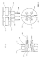
- FIG. 4 is a multi-view drawing of an example two-slot bobbin 402 according to one or more embodiments.
- the bobbin 402 includes a spindle 410 and flanges 406 connected to each end of the spindle 410.
- Two slots 412 are defined by the spindle 410, flanges 406, and a dividing section 414.
- the slots 412 are configured to hold multiple windings of a transmitter coil and/or a receiver coil. In some example windings, each slot can contain both receiver coil windings and transmitter coil windings.
- two receiver coils may be placed respectively in the two slots 412, and the windings of a transmitter coil may be divided into two halves, with each half placed in one of the two slots 412 with one of the receiver coils.
- This configuration is only intended to be exemplary, and it is to be appreciated that any winding configuration in which windings of separate coils share a common slot on a bobbin is within the scope of one or more embodiments of this disclosure.
- the size of bobbin 402 can be kept small relative to bobbin designs in which each coil must reside in a separate slot.
- co-locating all or portions of separate coils within common slots can reduce the resulting sensor's sensitivity to temperature and surrounding metals.
- Pins 404 protrude from one of the flanges 406, and server as terminals for the coil ends.
- Bobbin 402 includes six pins, providing terminals for three coils (e.g., one transmitter coil and two receiver coils).
- the pins 404 can be manufactured from any suitable conductive material. In some embodiments, pins 404 may be coated with a phosphorous bronze solder coating.
- Bobbin 402 may also include notches 408 in the flanges 406 and dividing section 414, yielding open channels on opposite sides of the bobbin that run through both flanges and the dividing section.
- a hole 416 runs through the flanges 406 and spindle 410 to facilitate location and mounting of the bobbin 402 within the sensor.
- FIGs 5-6 illustrate various methodologies in accordance with one or more embodiments of the subject application. While, for purposes of simplicity of explanation, the one or more methodologies shown herein are shown and described as a series of acts, it is to be understood and appreciated that the subject innovation is not limited by the order of acts, as some acts may, in accordance therewith, occur in a different order and/or concurrently with other acts from that shown and described herein. For example, those skilled in the art will understand and appreciate that a methodology could alternatively be represented as a series of interrelated states or events, such as in a state diagram. Moreover, not all illustrated acts may be required to implement a methodology in accordance with the innovation.
- interaction diagram(s) may represent methodologies, or methods, in accordance with the subject disclosure when disparate entities enact disparate portions of the methodologies.
- two or more of the disclosed example methods can be implemented in combination with each other, to accomplish one or more features or advantages described herein.
- FIG. 5 illustrates an example methodology 500 for winding coils of an inductive sensor.
- a first portion of a first coil of an inductive sensor is wound within a slot of a bobbin.
- the first coil may be a receiver coil or a transmitter coil of the sensor.
- at 504 at least a second portion of a second coil of the inductive sensor is wound within the slot, thereby causing the two coils (or coil portions) to reside in the same slot.
- FIG. 6 illustrates an example methodology 600 for winding coils of an inductive sensor comprising two receiver coils and one transmitter coil.
- a first receiver coil of an inductive sensor is wound within a first slot of a bobbin.
- a second receiver coil of the inductive sensor is wound within a second slot of the bobbin.
- a first portion of a transmitter coil of the inductive sensor is wound within the first slot.
- the first portion may be half or approximately half of the total number of transmitter coil windings. However, the first portion may be some other subset of the total number of transmitter coil windings.
- both the first receiver coil and the first portion of the transmitter coils are located within the first slot of the bobbin.
- a second portion of the transmitter coil e.g., the remaining windings of the transmitter coil after the first portion has been wound into the first slot
- is wound into the second slot thereby placing the second portion of the transmitter coil within the same slot as the second receiver coil.
- the terms (including a reference to a "means") used to describe such components are intended to correspond, unless otherwise indicated, to any component which performs the specified function of the described component (e.g., a functional equivalent), even though not structurally equivalent to the disclosed structure, which performs the function in the herein illustrated exemplary aspects of the disclosed subject matter.
- the disclosed subject matter includes a system as well as a computer-readable medium having computer-executable instructions for performing the acts and/or events of the various methods of the disclosed subject matter.
- exemplary is used to mean serving as an example, instance, or illustration. Any aspect or design described herein as "exemplary” is not necessarily to be construed as preferred or advantageous over other aspects or designs. Rather, use of the word exemplary is intended to present concepts in a concrete fashion.
- Computer readable media can include but are not limited to magnetic storage devices (e.g., hard disk, floppy disk, magnetic strips...), optical disks [e.g., compact disk (CD), digital versatile disk (DVD)...], smart cards, and flash memory devices (e.g., card, stick, key drive).
- magnetic storage devices e.g., hard disk, floppy disk, magnetic strips
- optical disks e.g., compact disk (CD), digital versatile disk (DVD)...
- smart cards e.g., card, stick, key drive
Landscapes
- Engineering & Computer Science (AREA)
- Power Engineering (AREA)
- Physics & Mathematics (AREA)
- Remote Sensing (AREA)
- Life Sciences & Earth Sciences (AREA)
- General Physics & Mathematics (AREA)
- Electromagnetism (AREA)
- Environmental & Geological Engineering (AREA)
- Geology (AREA)
- General Life Sciences & Earth Sciences (AREA)
- Geophysics (AREA)
- Manufacturing & Machinery (AREA)
- Investigating Or Analyzing Materials By The Use Of Magnetic Means (AREA)
- Measurement Of Length, Angles, Or The Like Using Electric Or Magnetic Means (AREA)
- Geophysics And Detection Of Objects (AREA)
Applications Claiming Priority (1)
| Application Number | Priority Date | Filing Date | Title |
|---|---|---|---|
| US14/319,844 US10145873B2 (en) | 2014-06-30 | 2014-06-30 | Coil architecture for inductive sensors |
Publications (2)
| Publication Number | Publication Date |
|---|---|
| EP2966656A1 true EP2966656A1 (de) | 2016-01-13 |
| EP2966656B1 EP2966656B1 (de) | 2017-09-13 |
Family
ID=53498886
Family Applications (1)
| Application Number | Title | Priority Date | Filing Date |
|---|---|---|---|
| EP15174543.7A Active EP2966656B1 (de) | 2014-06-30 | 2015-06-30 | Spulenarchitektur für induktivsensoren |
Country Status (3)
| Country | Link |
|---|---|
| US (1) | US10145873B2 (de) |
| EP (1) | EP2966656B1 (de) |
| CN (1) | CN105222813B (de) |
Families Citing this family (3)
| Publication number | Priority date | Publication date | Assignee | Title |
|---|---|---|---|---|
| US11721476B1 (en) * | 2015-11-05 | 2023-08-08 | St Jude Medical International Holding S.À R.L. | Sensor coil assembly |
| US10393908B2 (en) * | 2016-12-15 | 2019-08-27 | Rockwell Automation Technologies, Inc. | Bobbin construction and coil winding method |
| US20250315073A1 (en) * | 2024-04-03 | 2025-10-09 | Cts Corporation | Radially decoupled dual inductive position sensing arrangement |
Citations (5)
| Publication number | Priority date | Publication date | Assignee | Title |
|---|---|---|---|---|
| US4862316A (en) * | 1988-02-29 | 1989-08-29 | White's Electronics, Inc. | Static charge dissipating housing for metal detector search loop assembly |
| US20080278154A1 (en) * | 2005-12-23 | 2008-11-13 | Reiner Krapf | Device for Determining an Object, in Particular a Locating Device or Material Identification Device |
| US20080303517A1 (en) * | 2004-09-29 | 2008-12-11 | Uwe Skultety-Betz | Sensor For Locating Metallic Objects and Method For Evaluating Measurement Signal of Such a Sensor |
| DE102012202825A1 (de) * | 2012-02-24 | 2013-08-29 | Ifm Electronic Gmbh | Induktiver Näherungsschalter |
| DE102012012680A1 (de) * | 2012-06-27 | 2014-01-02 | Eva Hartmann | Sensoreinrichtung |
Family Cites Families (13)
| Publication number | Priority date | Publication date | Assignee | Title |
|---|---|---|---|---|
| US4074210A (en) * | 1975-08-20 | 1978-02-14 | Matsushita Electric Industrial Co., Ltd. | Distribution type delay line |
| JPS6254409A (ja) * | 1985-09-03 | 1987-03-10 | Murata Mfg Co Ltd | ノイズ除去用インダクタ |
| JP2974967B2 (ja) * | 1996-04-27 | 1999-11-10 | ティーディーケイ株式会社 | コンバータトランス |
| PL1641107T3 (pl) * | 2003-06-27 | 2016-10-31 | Silnik krokowy i sposób jego wytwarzania | |
| WO2008054429A2 (en) * | 2005-11-15 | 2008-05-08 | Zolo Technologies, Inc. | All-fiber architecture for an embedded flight sensor for aeropropulsion applications |
| TWI322438B (en) * | 2006-07-28 | 2010-03-21 | Delta Electronics Inc | Wave-filtering inductor |
| CN102175619B (zh) * | 2011-02-16 | 2013-02-06 | 武汉理工大学 | 多层复合敏感膜光纤氢气传感探头及其制作方法 |
| CN102230889A (zh) * | 2011-06-22 | 2011-11-02 | 天津大学 | 基于超连续谱光源的气体浓度测量系统及测量方法 |
| CN105158256B (zh) * | 2015-09-30 | 2017-08-29 | 山东大学 | 一种复合材料在线健康监测方法 |
| CN105424651B (zh) * | 2015-12-21 | 2018-10-19 | 安徽中科智泰光电测控科技有限公司 | 一种可定位的甲烷泄漏监测系统 |
| CN106198409B (zh) * | 2016-07-26 | 2018-08-21 | 重庆大学 | 一种油气浓度多参量检测装置 |
| CN206248102U (zh) * | 2016-12-13 | 2017-06-13 | 山东大学 | 一种纤维复合材料热模压固化变形光纤监测装置 |
| CN206696179U (zh) * | 2017-05-10 | 2017-12-01 | 李俊 | 一种用于易挥发碳氢化合物监测的传感器及系统 |
-
2014
- 2014-06-30 US US14/319,844 patent/US10145873B2/en active Active
-
2015
- 2015-06-30 CN CN201510397044.7A patent/CN105222813B/zh active Active
- 2015-06-30 EP EP15174543.7A patent/EP2966656B1/de active Active
Patent Citations (5)
| Publication number | Priority date | Publication date | Assignee | Title |
|---|---|---|---|---|
| US4862316A (en) * | 1988-02-29 | 1989-08-29 | White's Electronics, Inc. | Static charge dissipating housing for metal detector search loop assembly |
| US20080303517A1 (en) * | 2004-09-29 | 2008-12-11 | Uwe Skultety-Betz | Sensor For Locating Metallic Objects and Method For Evaluating Measurement Signal of Such a Sensor |
| US20080278154A1 (en) * | 2005-12-23 | 2008-11-13 | Reiner Krapf | Device for Determining an Object, in Particular a Locating Device or Material Identification Device |
| DE102012202825A1 (de) * | 2012-02-24 | 2013-08-29 | Ifm Electronic Gmbh | Induktiver Näherungsschalter |
| DE102012012680A1 (de) * | 2012-06-27 | 2014-01-02 | Eva Hartmann | Sensoreinrichtung |
Also Published As
| Publication number | Publication date |
|---|---|
| CN105222813B (zh) | 2019-08-13 |
| US10145873B2 (en) | 2018-12-04 |
| EP2966656B1 (de) | 2017-09-13 |
| US20150377940A1 (en) | 2015-12-31 |
| CN105222813A (zh) | 2016-01-06 |
Similar Documents
| Publication | Publication Date | Title |
|---|---|---|
| US9671484B2 (en) | Magnetic sensor test apparatus and method of testing a magnetic sensor | |
| US20200200937A1 (en) | Foreign Object Detection Circuit Using Mutual Impedance Sensing | |
| US11143732B2 (en) | Magnetic field sensor with modulated diagnostic signal | |
| US10516394B2 (en) | Sensor element of an inductive proximity or distance sensor containing coil arrangement having electrically-conductive shielding with flange completely enclosing the coil arrangement and method for operating the sensor element | |
| JP6364092B2 (ja) | リニアアクチュエータにおける誘導位置センシング | |
| US20180205265A1 (en) | Wireless power transmitter | |
| US20150048817A1 (en) | Position detection device and a drive device | |
| US10379176B2 (en) | Single-chip high-magnetic-field X-axis linear magnetoresistive sensor with calibration and initialization coil | |
| JP6593825B2 (ja) | 非接触型センサー | |
| BR102018076403B1 (pt) | Máquina classificadora | |
| EP2966656A1 (de) | Spulenarchitektur für induktivsensoren | |
| CN113474665B (zh) | 用于监控电导线的方法 | |
| US10809101B2 (en) | Curvilinear encoder system for position determination | |
| JP2013231720A (ja) | アーク故障検出装置及び方法 | |
| JP2022548498A (ja) | 差動信号電流センサ | |
| KR102274651B1 (ko) | 변압기를 테스트하기 위한 방법 | |
| US11927647B2 (en) | Current measurement device, current measurement method, and non-transitory computer readable storage medium | |
| US20150042343A1 (en) | Object finder | |
| JP6372458B2 (ja) | 送電装置、受電装置、及び非接触電力伝送システム | |
| JP2018501489A (ja) | 位置センサー | |
| US10502642B2 (en) | Non-contact magnetostrictive stress sensor with gap compensation field | |
| WO2016063094A1 (en) | Micro energy harvesting device for ac machines serving as a diagnostic probe | |
| JP2015021743A (ja) | 電流波形測定装置 | |
| KR101421110B1 (ko) | 인덕턴스방식 근접센서 | |
| KR20200020082A (ko) | 터치센서 모듈 |
Legal Events
| Date | Code | Title | Description |
|---|---|---|---|
| PUAI | Public reference made under article 153(3) epc to a published international application that has entered the european phase |
Free format text: ORIGINAL CODE: 0009012 |
|
| AK | Designated contracting states |
Kind code of ref document: A1 Designated state(s): AL AT BE BG CH CY CZ DE DK EE ES FI FR GB GR HR HU IE IS IT LI LT LU LV MC MK MT NL NO PL PT RO RS SE SI SK SM TR |
|
| AX | Request for extension of the european patent |
Extension state: BA ME |
|
| 17P | Request for examination filed |
Effective date: 20160705 |
|
| RBV | Designated contracting states (corrected) |
Designated state(s): AL AT BE BG CH CY CZ DE DK EE ES FI FR GB GR HR HU IE IS IT LI LT LU LV MC MK MT NL NO PL PT RO RS SE SI SK SM TR |
|
| REG | Reference to a national code |
Ref country code: DE Ref legal event code: R079 Ref document number: 602015004623 Country of ref document: DE Free format text: PREVIOUS MAIN CLASS: H01F0005020000 Ipc: H01F0021020000 |
|
| GRAP | Despatch of communication of intention to grant a patent |
Free format text: ORIGINAL CODE: EPIDOSNIGR1 |
|
| RIC1 | Information provided on ipc code assigned before grant |
Ipc: H01F 5/02 20060101ALI20170421BHEP Ipc: H01F 27/28 20060101ALI20170421BHEP Ipc: H01F 27/30 20060101ALI20170421BHEP Ipc: H01F 41/06 20160101ALI20170421BHEP Ipc: H01F 27/40 20060101ALI20170421BHEP Ipc: H01F 27/32 20060101ALI20170421BHEP Ipc: H01F 21/02 20060101AFI20170421BHEP |
|
| INTG | Intention to grant announced |
Effective date: 20170516 |
|
| GRAS | Grant fee paid |
Free format text: ORIGINAL CODE: EPIDOSNIGR3 |
|
| GRAA | (expected) grant |
Free format text: ORIGINAL CODE: 0009210 |
|
| AK | Designated contracting states |
Kind code of ref document: B1 Designated state(s): AL AT BE BG CH CY CZ DE DK EE ES FI FR GB GR HR HU IE IS IT LI LT LU LV MC MK MT NL NO PL PT RO RS SE SI SK SM TR |
|
| REG | Reference to a national code |
Ref country code: GB Ref legal event code: FG4D |
|
| REG | Reference to a national code |
Ref country code: CH Ref legal event code: EP |
|
| REG | Reference to a national code |
Ref country code: IE Ref legal event code: FG4D |
|
| REG | Reference to a national code |
Ref country code: AT Ref legal event code: REF Ref document number: 928893 Country of ref document: AT Kind code of ref document: T Effective date: 20171015 |
|
| REG | Reference to a national code |
Ref country code: DE Ref legal event code: R096 Ref document number: 602015004623 Country of ref document: DE |
|
| REG | Reference to a national code |
Ref country code: NL Ref legal event code: MP Effective date: 20170913 |
|
| REG | Reference to a national code |
Ref country code: LT Ref legal event code: MG4D |
|
| PG25 | Lapsed in a contracting state [announced via postgrant information from national office to epo] |
Ref country code: LT Free format text: LAPSE BECAUSE OF FAILURE TO SUBMIT A TRANSLATION OF THE DESCRIPTION OR TO PAY THE FEE WITHIN THE PRESCRIBED TIME-LIMIT Effective date: 20170913 Ref country code: NO Free format text: LAPSE BECAUSE OF FAILURE TO SUBMIT A TRANSLATION OF THE DESCRIPTION OR TO PAY THE FEE WITHIN THE PRESCRIBED TIME-LIMIT Effective date: 20171213 Ref country code: HR Free format text: LAPSE BECAUSE OF FAILURE TO SUBMIT A TRANSLATION OF THE DESCRIPTION OR TO PAY THE FEE WITHIN THE PRESCRIBED TIME-LIMIT Effective date: 20170913 Ref country code: SE Free format text: LAPSE BECAUSE OF FAILURE TO SUBMIT A TRANSLATION OF THE DESCRIPTION OR TO PAY THE FEE WITHIN THE PRESCRIBED TIME-LIMIT Effective date: 20170913 Ref country code: FI Free format text: LAPSE BECAUSE OF FAILURE TO SUBMIT A TRANSLATION OF THE DESCRIPTION OR TO PAY THE FEE WITHIN THE PRESCRIBED TIME-LIMIT Effective date: 20170913 |
|
| REG | Reference to a national code |
Ref country code: AT Ref legal event code: MK05 Ref document number: 928893 Country of ref document: AT Kind code of ref document: T Effective date: 20170913 |
|
| PG25 | Lapsed in a contracting state [announced via postgrant information from national office to epo] |
Ref country code: BG Free format text: LAPSE BECAUSE OF FAILURE TO SUBMIT A TRANSLATION OF THE DESCRIPTION OR TO PAY THE FEE WITHIN THE PRESCRIBED TIME-LIMIT Effective date: 20171213 Ref country code: RS Free format text: LAPSE BECAUSE OF FAILURE TO SUBMIT A TRANSLATION OF THE DESCRIPTION OR TO PAY THE FEE WITHIN THE PRESCRIBED TIME-LIMIT Effective date: 20170913 Ref country code: LV Free format text: LAPSE BECAUSE OF FAILURE TO SUBMIT A TRANSLATION OF THE DESCRIPTION OR TO PAY THE FEE WITHIN THE PRESCRIBED TIME-LIMIT Effective date: 20170913 Ref country code: GR Free format text: LAPSE BECAUSE OF FAILURE TO SUBMIT A TRANSLATION OF THE DESCRIPTION OR TO PAY THE FEE WITHIN THE PRESCRIBED TIME-LIMIT Effective date: 20171214 Ref country code: ES Free format text: LAPSE BECAUSE OF FAILURE TO SUBMIT A TRANSLATION OF THE DESCRIPTION OR TO PAY THE FEE WITHIN THE PRESCRIBED TIME-LIMIT Effective date: 20170913 |
|
| PG25 | Lapsed in a contracting state [announced via postgrant information from national office to epo] |
Ref country code: NL Free format text: LAPSE BECAUSE OF FAILURE TO SUBMIT A TRANSLATION OF THE DESCRIPTION OR TO PAY THE FEE WITHIN THE PRESCRIBED TIME-LIMIT Effective date: 20170913 |
|
| PG25 | Lapsed in a contracting state [announced via postgrant information from national office to epo] |
Ref country code: RO Free format text: LAPSE BECAUSE OF FAILURE TO SUBMIT A TRANSLATION OF THE DESCRIPTION OR TO PAY THE FEE WITHIN THE PRESCRIBED TIME-LIMIT Effective date: 20170913 Ref country code: CZ Free format text: LAPSE BECAUSE OF FAILURE TO SUBMIT A TRANSLATION OF THE DESCRIPTION OR TO PAY THE FEE WITHIN THE PRESCRIBED TIME-LIMIT Effective date: 20170913 Ref country code: PL Free format text: LAPSE BECAUSE OF FAILURE TO SUBMIT A TRANSLATION OF THE DESCRIPTION OR TO PAY THE FEE WITHIN THE PRESCRIBED TIME-LIMIT Effective date: 20170913 |
|
| PG25 | Lapsed in a contracting state [announced via postgrant information from national office to epo] |
Ref country code: EE Free format text: LAPSE BECAUSE OF FAILURE TO SUBMIT A TRANSLATION OF THE DESCRIPTION OR TO PAY THE FEE WITHIN THE PRESCRIBED TIME-LIMIT Effective date: 20170913 Ref country code: SM Free format text: LAPSE BECAUSE OF FAILURE TO SUBMIT A TRANSLATION OF THE DESCRIPTION OR TO PAY THE FEE WITHIN THE PRESCRIBED TIME-LIMIT Effective date: 20170913 Ref country code: SK Free format text: LAPSE BECAUSE OF FAILURE TO SUBMIT A TRANSLATION OF THE DESCRIPTION OR TO PAY THE FEE WITHIN THE PRESCRIBED TIME-LIMIT Effective date: 20170913 Ref country code: AT Free format text: LAPSE BECAUSE OF FAILURE TO SUBMIT A TRANSLATION OF THE DESCRIPTION OR TO PAY THE FEE WITHIN THE PRESCRIBED TIME-LIMIT Effective date: 20170913 Ref country code: IT Free format text: LAPSE BECAUSE OF FAILURE TO SUBMIT A TRANSLATION OF THE DESCRIPTION OR TO PAY THE FEE WITHIN THE PRESCRIBED TIME-LIMIT Effective date: 20170913 Ref country code: IS Free format text: LAPSE BECAUSE OF FAILURE TO SUBMIT A TRANSLATION OF THE DESCRIPTION OR TO PAY THE FEE WITHIN THE PRESCRIBED TIME-LIMIT Effective date: 20180113 |
|
| REG | Reference to a national code |
Ref country code: DE Ref legal event code: R097 Ref document number: 602015004623 Country of ref document: DE |
|
| REG | Reference to a national code |
Ref country code: FR Ref legal event code: PLFP Year of fee payment: 4 |
|
| PLBE | No opposition filed within time limit |
Free format text: ORIGINAL CODE: 0009261 |
|
| STAA | Information on the status of an ep patent application or granted ep patent |
Free format text: STATUS: NO OPPOSITION FILED WITHIN TIME LIMIT |
|
| PG25 | Lapsed in a contracting state [announced via postgrant information from national office to epo] |
Ref country code: DK Free format text: LAPSE BECAUSE OF FAILURE TO SUBMIT A TRANSLATION OF THE DESCRIPTION OR TO PAY THE FEE WITHIN THE PRESCRIBED TIME-LIMIT Effective date: 20170913 |
|
| 26N | No opposition filed |
Effective date: 20180614 |
|
| PG25 | Lapsed in a contracting state [announced via postgrant information from national office to epo] |
Ref country code: SI Free format text: LAPSE BECAUSE OF FAILURE TO SUBMIT A TRANSLATION OF THE DESCRIPTION OR TO PAY THE FEE WITHIN THE PRESCRIBED TIME-LIMIT Effective date: 20170913 |
|
| REG | Reference to a national code |
Ref country code: CH Ref legal event code: PL |
|
| REG | Reference to a national code |
Ref country code: BE Ref legal event code: MM Effective date: 20180630 |
|
| PG25 | Lapsed in a contracting state [announced via postgrant information from national office to epo] |
Ref country code: LU Free format text: LAPSE BECAUSE OF NON-PAYMENT OF DUE FEES Effective date: 20180630 Ref country code: MC Free format text: LAPSE BECAUSE OF FAILURE TO SUBMIT A TRANSLATION OF THE DESCRIPTION OR TO PAY THE FEE WITHIN THE PRESCRIBED TIME-LIMIT Effective date: 20170913 |
|
| REG | Reference to a national code |
Ref country code: IE Ref legal event code: MM4A |
|
| PG25 | Lapsed in a contracting state [announced via postgrant information from national office to epo] |
Ref country code: IE Free format text: LAPSE BECAUSE OF NON-PAYMENT OF DUE FEES Effective date: 20180630 Ref country code: CH Free format text: LAPSE BECAUSE OF NON-PAYMENT OF DUE FEES Effective date: 20180630 Ref country code: LI Free format text: LAPSE BECAUSE OF NON-PAYMENT OF DUE FEES Effective date: 20180630 |
|
| PG25 | Lapsed in a contracting state [announced via postgrant information from national office to epo] |
Ref country code: BE Free format text: LAPSE BECAUSE OF NON-PAYMENT OF DUE FEES Effective date: 20180630 |
|
| PG25 | Lapsed in a contracting state [announced via postgrant information from national office to epo] |
Ref country code: MT Free format text: LAPSE BECAUSE OF NON-PAYMENT OF DUE FEES Effective date: 20180630 |
|
| PG25 | Lapsed in a contracting state [announced via postgrant information from national office to epo] |
Ref country code: TR Free format text: LAPSE BECAUSE OF FAILURE TO SUBMIT A TRANSLATION OF THE DESCRIPTION OR TO PAY THE FEE WITHIN THE PRESCRIBED TIME-LIMIT Effective date: 20170913 |
|
| PG25 | Lapsed in a contracting state [announced via postgrant information from national office to epo] |
Ref country code: PT Free format text: LAPSE BECAUSE OF FAILURE TO SUBMIT A TRANSLATION OF THE DESCRIPTION OR TO PAY THE FEE WITHIN THE PRESCRIBED TIME-LIMIT Effective date: 20170913 |
|
| PG25 | Lapsed in a contracting state [announced via postgrant information from national office to epo] |
Ref country code: CY Free format text: LAPSE BECAUSE OF FAILURE TO SUBMIT A TRANSLATION OF THE DESCRIPTION OR TO PAY THE FEE WITHIN THE PRESCRIBED TIME-LIMIT Effective date: 20170913 Ref country code: MK Free format text: LAPSE BECAUSE OF NON-PAYMENT OF DUE FEES Effective date: 20170913 Ref country code: HU Free format text: LAPSE BECAUSE OF FAILURE TO SUBMIT A TRANSLATION OF THE DESCRIPTION OR TO PAY THE FEE WITHIN THE PRESCRIBED TIME-LIMIT; INVALID AB INITIO Effective date: 20150630 |
|
| PG25 | Lapsed in a contracting state [announced via postgrant information from national office to epo] |
Ref country code: AL Free format text: LAPSE BECAUSE OF FAILURE TO SUBMIT A TRANSLATION OF THE DESCRIPTION OR TO PAY THE FEE WITHIN THE PRESCRIBED TIME-LIMIT Effective date: 20170913 |
|
| P01 | Opt-out of the competence of the unified patent court (upc) registered |
Effective date: 20230404 |
|
| PGFP | Annual fee paid to national office [announced via postgrant information from national office to epo] |
Ref country code: DE Payment date: 20250520 Year of fee payment: 11 |
|
| PGFP | Annual fee paid to national office [announced via postgrant information from national office to epo] |
Ref country code: GB Payment date: 20250520 Year of fee payment: 11 |
|
| PGFP | Annual fee paid to national office [announced via postgrant information from national office to epo] |
Ref country code: FR Payment date: 20250520 Year of fee payment: 11 |