EP2966748A1 - Système de gestion d'énergie, procédé de gestion d'énergie, programme, et serveur - Google Patents
Système de gestion d'énergie, procédé de gestion d'énergie, programme, et serveur Download PDFInfo
- Publication number
- EP2966748A1 EP2966748A1 EP13824085.8A EP13824085A EP2966748A1 EP 2966748 A1 EP2966748 A1 EP 2966748A1 EP 13824085 A EP13824085 A EP 13824085A EP 2966748 A1 EP2966748 A1 EP 2966748A1
- Authority
- EP
- European Patent Office
- Prior art keywords
- energy
- customer
- water heater
- operation schedule
- hot water
- Prior art date
- Legal status (The legal status is an assumption and is not a legal conclusion. Google has not performed a legal analysis and makes no representation as to the accuracy of the status listed.)
- Withdrawn
Links
Images



Classifications
-
- G—PHYSICS
- G06—COMPUTING OR CALCULATING; COUNTING
- G06Q—INFORMATION AND COMMUNICATION TECHNOLOGY [ICT] SPECIALLY ADAPTED FOR ADMINISTRATIVE, COMMERCIAL, FINANCIAL, MANAGERIAL OR SUPERVISORY PURPOSES; SYSTEMS OR METHODS SPECIALLY ADAPTED FOR ADMINISTRATIVE, COMMERCIAL, FINANCIAL, MANAGERIAL OR SUPERVISORY PURPOSES, NOT OTHERWISE PROVIDED FOR
- G06Q50/00—Information and communication technology [ICT] specially adapted for implementation of business processes of specific business sectors, e.g. utilities or tourism
- G06Q50/06—Energy or water supply
-
- F—MECHANICAL ENGINEERING; LIGHTING; HEATING; WEAPONS; BLASTING
- F24—HEATING; RANGES; VENTILATING
- F24D—DOMESTIC- OR SPACE-HEATING SYSTEMS, e.g. CENTRAL HEATING SYSTEMS; DOMESTIC HOT-WATER SUPPLY SYSTEMS; ELEMENTS OR COMPONENTS THEREFOR
- F24D19/00—Details
- F24D19/10—Arrangement or mounting of control or safety devices
- F24D19/1006—Arrangement or mounting of control or safety devices for water heating systems
- F24D19/1066—Arrangement or mounting of control or safety devices for water heating systems for the combination of central heating and domestic hot water
- F24D19/1081—Arrangement or mounting of control or safety devices for water heating systems for the combination of central heating and domestic hot water counting of energy consumption
-
- F—MECHANICAL ENGINEERING; LIGHTING; HEATING; WEAPONS; BLASTING
- F24—HEATING; RANGES; VENTILATING
- F24H—FLUID HEATERS, e.g. WATER OR AIR HEATERS, HAVING HEAT-GENERATING MEANS, e.g. HEAT PUMPS, IN GENERAL
- F24H15/00—Control of fluid heaters
- F24H15/10—Control of fluid heaters characterised by the purpose of the control
- F24H15/144—Measuring or calculating energy consumption
-
- F—MECHANICAL ENGINEERING; LIGHTING; HEATING; WEAPONS; BLASTING
- F24—HEATING; RANGES; VENTILATING
- F24H—FLUID HEATERS, e.g. WATER OR AIR HEATERS, HAVING HEAT-GENERATING MEANS, e.g. HEAT PUMPS, IN GENERAL
- F24H15/00—Control of fluid heaters
- F24H15/10—Control of fluid heaters characterised by the purpose of the control
- F24H15/144—Measuring or calculating energy consumption
- F24H15/148—Assessing the current energy consumption
-
- F—MECHANICAL ENGINEERING; LIGHTING; HEATING; WEAPONS; BLASTING
- F24—HEATING; RANGES; VENTILATING
- F24H—FLUID HEATERS, e.g. WATER OR AIR HEATERS, HAVING HEAT-GENERATING MEANS, e.g. HEAT PUMPS, IN GENERAL
- F24H15/00—Control of fluid heaters
- F24H15/20—Control of fluid heaters characterised by control inputs
- F24H15/277—Price
-
- F—MECHANICAL ENGINEERING; LIGHTING; HEATING; WEAPONS; BLASTING
- F24—HEATING; RANGES; VENTILATING
- F24H—FLUID HEATERS, e.g. WATER OR AIR HEATERS, HAVING HEAT-GENERATING MEANS, e.g. HEAT PUMPS, IN GENERAL
- F24H15/00—Control of fluid heaters
- F24H15/40—Control of fluid heaters characterised by the type of controllers
- F24H15/414—Control of fluid heaters characterised by the type of controllers using electronic processing, e.g. computer-based
- F24H15/421—Control of fluid heaters characterised by the type of controllers using electronic processing, e.g. computer-based using pre-stored data
-
- G—PHYSICS
- G06—COMPUTING OR CALCULATING; COUNTING
- G06Q—INFORMATION AND COMMUNICATION TECHNOLOGY [ICT] SPECIALLY ADAPTED FOR ADMINISTRATIVE, COMMERCIAL, FINANCIAL, MANAGERIAL OR SUPERVISORY PURPOSES; SYSTEMS OR METHODS SPECIALLY ADAPTED FOR ADMINISTRATIVE, COMMERCIAL, FINANCIAL, MANAGERIAL OR SUPERVISORY PURPOSES, NOT OTHERWISE PROVIDED FOR
- G06Q10/00—Administration; Management
- G06Q10/06—Resources, workflows, human or project management; Enterprise or organisation planning; Enterprise or organisation modelling
-
- H—ELECTRICITY
- H02—GENERATION; CONVERSION OR DISTRIBUTION OF ELECTRIC POWER
- H02J—ELECTRIC POWER NETWORKS; CIRCUIT ARRANGEMENTS OR SYSTEMS FOR SUPPLYING OR DISTRIBUTING ELECTRIC POWER; SYSTEMS FOR STORING ELECTRIC ENERGY
- H02J3/00—Circuit arrangements for AC mains or AC distribution networks
- H02J3/008—Circuit arrangements for power supply or distribution technologies responsive to energy trading
-
- H—ELECTRICITY
- H02—GENERATION; CONVERSION OR DISTRIBUTION OF ELECTRIC POWER
- H02J—ELECTRIC POWER NETWORKS; CIRCUIT ARRANGEMENTS OR SYSTEMS FOR SUPPLYING OR DISTRIBUTING ELECTRIC POWER; SYSTEMS FOR STORING ELECTRIC ENERGY
- H02J3/00—Circuit arrangements for AC mains or AC distribution networks
- H02J3/12—Arrangements for adjusting voltage in AC networks by changing a characteristic of the network load
- H02J3/14—Arrangements for adjusting voltage in AC networks by changing a characteristic of the network load by switching loads on to, or off from, the networks, e.g. progressively balanced loading
-
- H—ELECTRICITY
- H02—GENERATION; CONVERSION OR DISTRIBUTION OF ELECTRIC POWER
- H02J—ELECTRIC POWER NETWORKS; CIRCUIT ARRANGEMENTS OR SYSTEMS FOR SUPPLYING OR DISTRIBUTING ELECTRIC POWER; SYSTEMS FOR STORING ELECTRIC ENERGY
- H02J3/00—Circuit arrangements for AC mains or AC distribution networks
- H02J3/38—Arrangements for feeding a single network from two or more generators or sources in parallel; Arrangements for feeding already energised networks from additional generators or sources in parallel
- H02J3/381—Dispersed generators
-
- H—ELECTRICITY
- H02—GENERATION; CONVERSION OR DISTRIBUTION OF ELECTRIC POWER
- H02J—ELECTRIC POWER NETWORKS; CIRCUIT ARRANGEMENTS OR SYSTEMS FOR SUPPLYING OR DISTRIBUTING ELECTRIC POWER; SYSTEMS FOR STORING ELECTRIC ENERGY
- H02J3/00—Circuit arrangements for AC mains or AC distribution networks
- H02J3/38—Arrangements for feeding a single network from two or more generators or sources in parallel; Arrangements for feeding already energised networks from additional generators or sources in parallel
- H02J3/46—Controlling the sharing of generated power between the generators, sources or networks
- H02J3/466—Scheduling or selectively controlling the operation of the generators or sources, e.g. connecting or disconnecting generators to meet a demand
-
- H—ELECTRICITY
- H02—GENERATION; CONVERSION OR DISTRIBUTION OF ELECTRIC POWER
- H02J—ELECTRIC POWER NETWORKS; CIRCUIT ARRANGEMENTS OR SYSTEMS FOR SUPPLYING OR DISTRIBUTING ELECTRIC POWER; SYSTEMS FOR STORING ELECTRIC ENERGY
- H02J7/00—Circuit arrangements for charging or discharging batteries or for supplying loads from batteries
- H02J7/34—Parallel operation in networks using both storage and other DC sources, e.g. providing buffering
- H02J7/35—Parallel operation in networks using both storage and other DC sources, e.g. providing buffering with light sensitive cells
-
- F—MECHANICAL ENGINEERING; LIGHTING; HEATING; WEAPONS; BLASTING
- F24—HEATING; RANGES; VENTILATING
- F24H—FLUID HEATERS, e.g. WATER OR AIR HEATERS, HAVING HEAT-GENERATING MEANS, e.g. HEAT PUMPS, IN GENERAL
- F24H15/00—Control of fluid heaters
- F24H15/30—Control of fluid heaters characterised by control outputs; characterised by the components to be controlled
- F24H15/395—Information to users, e.g. alarms
-
- F—MECHANICAL ENGINEERING; LIGHTING; HEATING; WEAPONS; BLASTING
- F24—HEATING; RANGES; VENTILATING
- F24H—FLUID HEATERS, e.g. WATER OR AIR HEATERS, HAVING HEAT-GENERATING MEANS, e.g. HEAT PUMPS, IN GENERAL
- F24H15/00—Control of fluid heaters
- F24H15/40—Control of fluid heaters characterised by the type of controllers
- F24H15/414—Control of fluid heaters characterised by the type of controllers using electronic processing, e.g. computer-based
- F24H15/45—Control of fluid heaters characterised by the type of controllers using electronic processing, e.g. computer-based remotely accessible
- F24H15/464—Control of fluid heaters characterised by the type of controllers using electronic processing, e.g. computer-based remotely accessible using local wireless communication
-
- H—ELECTRICITY
- H02—GENERATION; CONVERSION OR DISTRIBUTION OF ELECTRIC POWER
- H02J—ELECTRIC POWER NETWORKS; CIRCUIT ARRANGEMENTS OR SYSTEMS FOR SUPPLYING OR DISTRIBUTING ELECTRIC POWER; SYSTEMS FOR STORING ELECTRIC ENERGY
- H02J13/00—Circuit arrangements for providing remote monitoring or remote control of equipment in a power distribution network
- H02J13/13—Circuit arrangements for providing remote monitoring or remote control of equipment in a power distribution network characterised by the transmission of data to equipment in the power network
- H02J13/1321—Circuit arrangements for providing remote monitoring or remote control of equipment in a power distribution network characterised by the transmission of data to equipment in the power network using a wired telecommunication network or a data transmission bus
-
- H—ELECTRICITY
- H02—GENERATION; CONVERSION OR DISTRIBUTION OF ELECTRIC POWER
- H02J—ELECTRIC POWER NETWORKS; CIRCUIT ARRANGEMENTS OR SYSTEMS FOR SUPPLYING OR DISTRIBUTING ELECTRIC POWER; SYSTEMS FOR STORING ELECTRIC ENERGY
- H02J13/00—Circuit arrangements for providing remote monitoring or remote control of equipment in a power distribution network
- H02J13/13—Circuit arrangements for providing remote monitoring or remote control of equipment in a power distribution network characterised by the transmission of data to equipment in the power network
- H02J13/1331—Circuit arrangements for providing remote monitoring or remote control of equipment in a power distribution network characterised by the transmission of data to equipment in the power network using wireless data transmission
-
- H—ELECTRICITY
- H02—GENERATION; CONVERSION OR DISTRIBUTION OF ELECTRIC POWER
- H02J—ELECTRIC POWER NETWORKS; CIRCUIT ARRANGEMENTS OR SYSTEMS FOR SUPPLYING OR DISTRIBUTING ELECTRIC POWER; SYSTEMS FOR STORING ELECTRIC ENERGY
- H02J13/00—Circuit arrangements for providing remote monitoring or remote control of equipment in a power distribution network
- H02J13/14—Circuit arrangements for providing remote monitoring or remote control of equipment in a power distribution network the power network being locally controlled, e.g. home energy management systems [HEMS]
-
- H—ELECTRICITY
- H02—GENERATION; CONVERSION OR DISTRIBUTION OF ELECTRIC POWER
- H02J—ELECTRIC POWER NETWORKS; CIRCUIT ARRANGEMENTS OR SYSTEMS FOR SUPPLYING OR DISTRIBUTING ELECTRIC POWER; SYSTEMS FOR STORING ELECTRIC ENERGY
- H02J13/00—Circuit arrangements for providing remote monitoring or remote control of equipment in a power distribution network
- H02J13/18—Circuit arrangements for providing remote monitoring or remote control of equipment in a power distribution network characterised by the remotely-controlled equipment, e.g. converters or transformers
- H02J13/333—Circuit arrangements for providing remote monitoring or remote control of equipment in a power distribution network characterised by the remotely-controlled equipment, e.g. converters or transformers the equipment forming part of substations
-
- H—ELECTRICITY
- H02—GENERATION; CONVERSION OR DISTRIBUTION OF ELECTRIC POWER
- H02J—ELECTRIC POWER NETWORKS; CIRCUIT ARRANGEMENTS OR SYSTEMS FOR SUPPLYING OR DISTRIBUTING ELECTRIC POWER; SYSTEMS FOR STORING ELECTRIC ENERGY
- H02J2101/00—Supply or distribution of decentralised, dispersed or local electric power generation
- H02J2101/20—Dispersed power generation using renewable energy sources
- H02J2101/22—Solar energy
-
- H—ELECTRICITY
- H02—GENERATION; CONVERSION OR DISTRIBUTION OF ELECTRIC POWER
- H02J—ELECTRIC POWER NETWORKS; CIRCUIT ARRANGEMENTS OR SYSTEMS FOR SUPPLYING OR DISTRIBUTING ELECTRIC POWER; SYSTEMS FOR STORING ELECTRIC ENERGY
- H02J2101/00—Supply or distribution of decentralised, dispersed or local electric power generation
- H02J2101/20—Dispersed power generation using renewable energy sources
- H02J2101/22—Solar energy
- H02J2101/24—Photovoltaics
-
- H—ELECTRICITY
- H02—GENERATION; CONVERSION OR DISTRIBUTION OF ELECTRIC POWER
- H02J—ELECTRIC POWER NETWORKS; CIRCUIT ARRANGEMENTS OR SYSTEMS FOR SUPPLYING OR DISTRIBUTING ELECTRIC POWER; SYSTEMS FOR STORING ELECTRIC ENERGY
- H02J2101/00—Supply or distribution of decentralised, dispersed or local electric power generation
- H02J2101/20—Dispersed power generation using renewable energy sources
- H02J2101/28—Wind energy
-
- H—ELECTRICITY
- H02—GENERATION; CONVERSION OR DISTRIBUTION OF ELECTRIC POWER
- H02J—ELECTRIC POWER NETWORKS; CIRCUIT ARRANGEMENTS OR SYSTEMS FOR SUPPLYING OR DISTRIBUTING ELECTRIC POWER; SYSTEMS FOR STORING ELECTRIC ENERGY
- H02J2101/00—Supply or distribution of decentralised, dispersed or local electric power generation
- H02J2101/20—Dispersed power generation using renewable energy sources
- H02J2101/30—Fuel cells
-
- H—ELECTRICITY
- H02—GENERATION; CONVERSION OR DISTRIBUTION OF ELECTRIC POWER
- H02J—ELECTRIC POWER NETWORKS; CIRCUIT ARRANGEMENTS OR SYSTEMS FOR SUPPLYING OR DISTRIBUTING ELECTRIC POWER; SYSTEMS FOR STORING ELECTRIC ENERGY
- H02J2105/00—Networks for supplying or distributing electric power characterised by their spatial reach or by the load
- H02J2105/10—Local stationary networks having a local or delimited stationary reach
- H02J2105/12—Local stationary networks having a local or delimited stationary reach supplying households or buildings
-
- H—ELECTRICITY
- H02—GENERATION; CONVERSION OR DISTRIBUTION OF ELECTRIC POWER
- H02J—ELECTRIC POWER NETWORKS; CIRCUIT ARRANGEMENTS OR SYSTEMS FOR SUPPLYING OR DISTRIBUTING ELECTRIC POWER; SYSTEMS FOR STORING ELECTRIC ENERGY
- H02J2105/00—Networks for supplying or distributing electric power characterised by their spatial reach or by the load
- H02J2105/40—Networks for supplying or distributing electric power characterised by their spatial reach or by the load characterised by the loads connecting to the networks or being supplied by the networks
- H02J2105/42—Home appliances
-
- Y—GENERAL TAGGING OF NEW TECHNOLOGICAL DEVELOPMENTS; GENERAL TAGGING OF CROSS-SECTIONAL TECHNOLOGIES SPANNING OVER SEVERAL SECTIONS OF THE IPC; TECHNICAL SUBJECTS COVERED BY FORMER USPC CROSS-REFERENCE ART COLLECTIONS [XRACs] AND DIGESTS
- Y02—TECHNOLOGIES OR APPLICATIONS FOR MITIGATION OR ADAPTATION AGAINST CLIMATE CHANGE
- Y02B—CLIMATE CHANGE MITIGATION TECHNOLOGIES RELATED TO BUILDINGS, e.g. HOUSING, HOUSE APPLIANCES OR RELATED END-USER APPLICATIONS
- Y02B30/00—Energy efficient heating, ventilation or air conditioning [HVAC]
- Y02B30/70—Efficient control or regulation technologies, e.g. for control of refrigerant flow, motor or heating
-
- Y—GENERAL TAGGING OF NEW TECHNOLOGICAL DEVELOPMENTS; GENERAL TAGGING OF CROSS-SECTIONAL TECHNOLOGIES SPANNING OVER SEVERAL SECTIONS OF THE IPC; TECHNICAL SUBJECTS COVERED BY FORMER USPC CROSS-REFERENCE ART COLLECTIONS [XRACs] AND DIGESTS
- Y02—TECHNOLOGIES OR APPLICATIONS FOR MITIGATION OR ADAPTATION AGAINST CLIMATE CHANGE
- Y02B—CLIMATE CHANGE MITIGATION TECHNOLOGIES RELATED TO BUILDINGS, e.g. HOUSING, HOUSE APPLIANCES OR RELATED END-USER APPLICATIONS
- Y02B70/00—Technologies for an efficient end-user side electric power management and consumption
- Y02B70/30—Systems integrating technologies related to power network operation and communication or information technologies for improving the carbon footprint of the management of residential or tertiary loads, i.e. smart grids as climate change mitigation technology in the buildings sector, including also the last stages of power distribution and the control, monitoring or operating management systems at local level
-
- Y—GENERAL TAGGING OF NEW TECHNOLOGICAL DEVELOPMENTS; GENERAL TAGGING OF CROSS-SECTIONAL TECHNOLOGIES SPANNING OVER SEVERAL SECTIONS OF THE IPC; TECHNICAL SUBJECTS COVERED BY FORMER USPC CROSS-REFERENCE ART COLLECTIONS [XRACs] AND DIGESTS
- Y02—TECHNOLOGIES OR APPLICATIONS FOR MITIGATION OR ADAPTATION AGAINST CLIMATE CHANGE
- Y02B—CLIMATE CHANGE MITIGATION TECHNOLOGIES RELATED TO BUILDINGS, e.g. HOUSING, HOUSE APPLIANCES OR RELATED END-USER APPLICATIONS
- Y02B70/00—Technologies for an efficient end-user side electric power management and consumption
- Y02B70/30—Systems integrating technologies related to power network operation and communication or information technologies for improving the carbon footprint of the management of residential or tertiary loads, i.e. smart grids as climate change mitigation technology in the buildings sector, including also the last stages of power distribution and the control, monitoring or operating management systems at local level
- Y02B70/3225—Demand response systems, e.g. load shedding, peak shaving
-
- Y—GENERAL TAGGING OF NEW TECHNOLOGICAL DEVELOPMENTS; GENERAL TAGGING OF CROSS-SECTIONAL TECHNOLOGIES SPANNING OVER SEVERAL SECTIONS OF THE IPC; TECHNICAL SUBJECTS COVERED BY FORMER USPC CROSS-REFERENCE ART COLLECTIONS [XRACs] AND DIGESTS
- Y02—TECHNOLOGIES OR APPLICATIONS FOR MITIGATION OR ADAPTATION AGAINST CLIMATE CHANGE
- Y02B—CLIMATE CHANGE MITIGATION TECHNOLOGIES RELATED TO BUILDINGS, e.g. HOUSING, HOUSE APPLIANCES OR RELATED END-USER APPLICATIONS
- Y02B90/00—Enabling technologies or technologies with a potential or indirect contribution to GHG emissions mitigation
- Y02B90/20—Smart grids as enabling technology in buildings sector
-
- Y—GENERAL TAGGING OF NEW TECHNOLOGICAL DEVELOPMENTS; GENERAL TAGGING OF CROSS-SECTIONAL TECHNOLOGIES SPANNING OVER SEVERAL SECTIONS OF THE IPC; TECHNICAL SUBJECTS COVERED BY FORMER USPC CROSS-REFERENCE ART COLLECTIONS [XRACs] AND DIGESTS
- Y02—TECHNOLOGIES OR APPLICATIONS FOR MITIGATION OR ADAPTATION AGAINST CLIMATE CHANGE
- Y02E—REDUCTION OF GREENHOUSE GAS [GHG] EMISSIONS, RELATED TO ENERGY GENERATION, TRANSMISSION OR DISTRIBUTION
- Y02E10/00—Energy generation through renewable energy sources
- Y02E10/50—Photovoltaic [PV] energy
- Y02E10/56—Power conversion systems, e.g. maximum power point trackers
-
- Y—GENERAL TAGGING OF NEW TECHNOLOGICAL DEVELOPMENTS; GENERAL TAGGING OF CROSS-SECTIONAL TECHNOLOGIES SPANNING OVER SEVERAL SECTIONS OF THE IPC; TECHNICAL SUBJECTS COVERED BY FORMER USPC CROSS-REFERENCE ART COLLECTIONS [XRACs] AND DIGESTS
- Y02—TECHNOLOGIES OR APPLICATIONS FOR MITIGATION OR ADAPTATION AGAINST CLIMATE CHANGE
- Y02E—REDUCTION OF GREENHOUSE GAS [GHG] EMISSIONS, RELATED TO ENERGY GENERATION, TRANSMISSION OR DISTRIBUTION
- Y02E10/00—Energy generation through renewable energy sources
- Y02E10/70—Wind energy
- Y02E10/76—Power conversion electric or electronic aspects
-
- Y—GENERAL TAGGING OF NEW TECHNOLOGICAL DEVELOPMENTS; GENERAL TAGGING OF CROSS-SECTIONAL TECHNOLOGIES SPANNING OVER SEVERAL SECTIONS OF THE IPC; TECHNICAL SUBJECTS COVERED BY FORMER USPC CROSS-REFERENCE ART COLLECTIONS [XRACs] AND DIGESTS
- Y04—INFORMATION OR COMMUNICATION TECHNOLOGIES HAVING AN IMPACT ON OTHER TECHNOLOGY AREAS
- Y04S—SYSTEMS INTEGRATING TECHNOLOGIES RELATED TO POWER NETWORK OPERATION, COMMUNICATION OR INFORMATION TECHNOLOGIES FOR IMPROVING THE ELECTRICAL POWER GENERATION, TRANSMISSION, DISTRIBUTION, MANAGEMENT OR USAGE, i.e. SMART GRIDS
- Y04S20/00—Management or operation of end-user stationary applications or the last stages of power distribution; Controlling, monitoring or operating thereof
- Y04S20/20—End-user application control systems
- Y04S20/221—General power management systems
-
- Y—GENERAL TAGGING OF NEW TECHNOLOGICAL DEVELOPMENTS; GENERAL TAGGING OF CROSS-SECTIONAL TECHNOLOGIES SPANNING OVER SEVERAL SECTIONS OF THE IPC; TECHNICAL SUBJECTS COVERED BY FORMER USPC CROSS-REFERENCE ART COLLECTIONS [XRACs] AND DIGESTS
- Y04—INFORMATION OR COMMUNICATION TECHNOLOGIES HAVING AN IMPACT ON OTHER TECHNOLOGY AREAS
- Y04S—SYSTEMS INTEGRATING TECHNOLOGIES RELATED TO POWER NETWORK OPERATION, COMMUNICATION OR INFORMATION TECHNOLOGIES FOR IMPROVING THE ELECTRICAL POWER GENERATION, TRANSMISSION, DISTRIBUTION, MANAGEMENT OR USAGE, i.e. SMART GRIDS
- Y04S20/00—Management or operation of end-user stationary applications or the last stages of power distribution; Controlling, monitoring or operating thereof
- Y04S20/20—End-user application control systems
- Y04S20/222—Demand response systems, e.g. load shedding, peak shaving
-
- Y—GENERAL TAGGING OF NEW TECHNOLOGICAL DEVELOPMENTS; GENERAL TAGGING OF CROSS-SECTIONAL TECHNOLOGIES SPANNING OVER SEVERAL SECTIONS OF THE IPC; TECHNICAL SUBJECTS COVERED BY FORMER USPC CROSS-REFERENCE ART COLLECTIONS [XRACs] AND DIGESTS
- Y04—INFORMATION OR COMMUNICATION TECHNOLOGIES HAVING AN IMPACT ON OTHER TECHNOLOGY AREAS
- Y04S—SYSTEMS INTEGRATING TECHNOLOGIES RELATED TO POWER NETWORK OPERATION, COMMUNICATION OR INFORMATION TECHNOLOGIES FOR IMPROVING THE ELECTRICAL POWER GENERATION, TRANSMISSION, DISTRIBUTION, MANAGEMENT OR USAGE, i.e. SMART GRIDS
- Y04S20/00—Management or operation of end-user stationary applications or the last stages of power distribution; Controlling, monitoring or operating thereof
- Y04S20/20—End-user application control systems
- Y04S20/242—Home appliances
-
- Y—GENERAL TAGGING OF NEW TECHNOLOGICAL DEVELOPMENTS; GENERAL TAGGING OF CROSS-SECTIONAL TECHNOLOGIES SPANNING OVER SEVERAL SECTIONS OF THE IPC; TECHNICAL SUBJECTS COVERED BY FORMER USPC CROSS-REFERENCE ART COLLECTIONS [XRACs] AND DIGESTS
- Y04—INFORMATION OR COMMUNICATION TECHNOLOGIES HAVING AN IMPACT ON OTHER TECHNOLOGY AREAS
- Y04S—SYSTEMS INTEGRATING TECHNOLOGIES RELATED TO POWER NETWORK OPERATION, COMMUNICATION OR INFORMATION TECHNOLOGIES FOR IMPROVING THE ELECTRICAL POWER GENERATION, TRANSMISSION, DISTRIBUTION, MANAGEMENT OR USAGE, i.e. SMART GRIDS
- Y04S20/00—Management or operation of end-user stationary applications or the last stages of power distribution; Controlling, monitoring or operating thereof
- Y04S20/20—End-user application control systems
- Y04S20/242—Home appliances
- Y04S20/244—Home appliances the home appliances being or involving heating ventilating and air conditioning [HVAC] units
-
- Y—GENERAL TAGGING OF NEW TECHNOLOGICAL DEVELOPMENTS; GENERAL TAGGING OF CROSS-SECTIONAL TECHNOLOGIES SPANNING OVER SEVERAL SECTIONS OF THE IPC; TECHNICAL SUBJECTS COVERED BY FORMER USPC CROSS-REFERENCE ART COLLECTIONS [XRACs] AND DIGESTS
- Y04—INFORMATION OR COMMUNICATION TECHNOLOGIES HAVING AN IMPACT ON OTHER TECHNOLOGY AREAS
- Y04S—SYSTEMS INTEGRATING TECHNOLOGIES RELATED TO POWER NETWORK OPERATION, COMMUNICATION OR INFORMATION TECHNOLOGIES FOR IMPROVING THE ELECTRICAL POWER GENERATION, TRANSMISSION, DISTRIBUTION, MANAGEMENT OR USAGE, i.e. SMART GRIDS
- Y04S40/00—Systems for electrical power generation, transmission, distribution or end-user application management characterised by the use of communication or information technologies, or communication or information technology specific aspects supporting them
- Y04S40/12—Systems for electrical power generation, transmission, distribution or end-user application management characterised by the use of communication or information technologies, or communication or information technology specific aspects supporting them characterised by data transport means between the monitoring, controlling or managing units and monitored, controlled or operated electrical equipment
- Y04S40/124—Systems for electrical power generation, transmission, distribution or end-user application management characterised by the use of communication or information technologies, or communication or information technology specific aspects supporting them characterised by data transport means between the monitoring, controlling or managing units and monitored, controlled or operated electrical equipment using wired telecommunication networks or data transmission busses
-
- Y—GENERAL TAGGING OF NEW TECHNOLOGICAL DEVELOPMENTS; GENERAL TAGGING OF CROSS-SECTIONAL TECHNOLOGIES SPANNING OVER SEVERAL SECTIONS OF THE IPC; TECHNICAL SUBJECTS COVERED BY FORMER USPC CROSS-REFERENCE ART COLLECTIONS [XRACs] AND DIGESTS
- Y04—INFORMATION OR COMMUNICATION TECHNOLOGIES HAVING AN IMPACT ON OTHER TECHNOLOGY AREAS
- Y04S—SYSTEMS INTEGRATING TECHNOLOGIES RELATED TO POWER NETWORK OPERATION, COMMUNICATION OR INFORMATION TECHNOLOGIES FOR IMPROVING THE ELECTRICAL POWER GENERATION, TRANSMISSION, DISTRIBUTION, MANAGEMENT OR USAGE, i.e. SMART GRIDS
- Y04S40/00—Systems for electrical power generation, transmission, distribution or end-user application management characterised by the use of communication or information technologies, or communication or information technology specific aspects supporting them
- Y04S40/12—Systems for electrical power generation, transmission, distribution or end-user application management characterised by the use of communication or information technologies, or communication or information technology specific aspects supporting them characterised by data transport means between the monitoring, controlling or managing units and monitored, controlled or operated electrical equipment
- Y04S40/126—Systems for electrical power generation, transmission, distribution or end-user application management characterised by the use of communication or information technologies, or communication or information technology specific aspects supporting them characterised by data transport means between the monitoring, controlling or managing units and monitored, controlled or operated electrical equipment using wireless data transmission
-
- Y—GENERAL TAGGING OF NEW TECHNOLOGICAL DEVELOPMENTS; GENERAL TAGGING OF CROSS-SECTIONAL TECHNOLOGIES SPANNING OVER SEVERAL SECTIONS OF THE IPC; TECHNICAL SUBJECTS COVERED BY FORMER USPC CROSS-REFERENCE ART COLLECTIONS [XRACs] AND DIGESTS
- Y04—INFORMATION OR COMMUNICATION TECHNOLOGIES HAVING AN IMPACT ON OTHER TECHNOLOGY AREAS
- Y04S—SYSTEMS INTEGRATING TECHNOLOGIES RELATED TO POWER NETWORK OPERATION, COMMUNICATION OR INFORMATION TECHNOLOGIES FOR IMPROVING THE ELECTRICAL POWER GENERATION, TRANSMISSION, DISTRIBUTION, MANAGEMENT OR USAGE, i.e. SMART GRIDS
- Y04S50/00—Market activities related to the operation of systems integrating technologies related to power network operation or related to communication or information technologies
- Y04S50/10—Energy trading, including energy flowing from end-user application to grid
Definitions
- Embodiments described herein relate generally to an energy management system for managing the energy balance on a customer side, an energy management method, a program, and a server.
- a zero energy home (ZEH) or a net zero energy home has received a great deal of attention against the background of recently increasing awareness of environmental preservation and anxiety about shortages in the supply of electricity.
- a net zero energy home is a home with an annual primary energy consumption of almost zero.
- distributed power supplies such as a PV (Photovoltaic power generation) system, a storage battery, and an FC (Fuel Cell) and a HEMS (Home Energy Management System) are indispensable.
- FC is most promising because it can stably generate power and supply heat energy using waste heat any time during the day or night, independently of the weather.
- FC is most promising because it can stably generate power and supply heat energy using waste heat any time during the day or night, independently of the weather.
- contractual agreements with electric power companies reverse power flow from the FC to a commercial power grid is not permitted.
- several techniques of preventing reverse flow of power generated by the FC have been proposed.
- an energy management system manages energy of a customer, including a water heater that uses renewable energy as a heat source.
- the energy management system includes an acquisition unit, an estimation unit, a creation unit, and a control unit.
- the acquisition unit acquires data concerning energy associated apparatuses including the water heater, a power generation device, a battery device, and an energy consuming device from the customer.
- the estimation unit estimates an energy demand and supply of the customer based on the data.
- the creation unit creates operation schedules based on the estimated demand and supply so as to minimize the energy cost of the customer under a condition that surplus power to be discarded when the battery device is fully charged is minimized.
- the control unit controls the energy associated apparatuses based on the operation schedules.
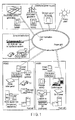
- FIG. 1 is a view showing an example of a system according to an embodiment.
- FIG. 1 illustrates an example of a system known as a so-called smart grid.
- existing power plants such as a nuclear power plant, a thermal power plant, and a hydroelectric power plant are connected to various customers such as an ordinary household, a building, and a factory via the grid.
- distributed power supplies such as a PV (Photovoltaic power generation) system and a wind power plant, battery devices, new transportation systems, charging stations, and the like are additionally connected to the power grid.
- PV Photovoltaic power generation
- the variety of elements can communicate via a communication grid.
- EMSs Electronic Management Systems
- HEMS Human Equipment
- BEMS Building Energy Management System
- MEMS Mansion Energy Management System
- CEMS Common Energy Management System
- FEMS Fractory Energy Management System
- an advanced cooperative operation can be performed between the existing power plants, the distributed power supplies, the renewable energy sources such as sunlight and wind, and the customers.
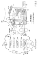
- FIG. 2 is a view showing an example of an energy management system according to the embodiment.
- the HEMS includes a client system, and a cloud computing system (to be abbreviated as a cloud hereinafter) 300.
- the cloud 300 can be understood as a server system capable of communicating with the client system.
- the client system includes a home gateway (HGW) 7 serving as a client apparatus.
- the home gateway 7 is a communication apparatus installed in a home 100, and can receive various kinds of services from the cloud 300.
- the cloud 300 includes a server computer SV and a database DB.
- the server computer SV can include a single or a plurality of server computers.
- the databases DB can be either provided in the single server computer SV or distributively stored in the plurality of server computers SV.
- power (AC voltage) supplied from a power grid 6 is distributed to households via, for example, a transformer 61 on a pole, and supplied to a distribution switchboard 20 in the home 100 via a watt-hour meter (smart meter) 19.
- the watt-hour meter 19 has a function of measuring the power generation amount of an energy generation device provided in the home 100, the power consumption of the home 100, the electric energy supplied from the power grid 6, the amount of reverse power flow to the power grid 6, or the like.
- power generated based on renewable energy is permitted to flow back to the power grid 6.
- the distribution switchboard 20 supplies, via distribution lines 21, power to household electric appliances (for example, lighting equipment, air conditioner, and heat pump water heater (HP)) 5 and a power conditioning system (PCS) 104 connected to the distribution switchboard 20.
- the distribution switchboard 20 also includes a measuring device for measuring the electric energy of each feeder.
- the home 100 includes electrical apparatuses.
- the electrical apparatuses are apparatuses connectable to the distribution lines 21 in the home 100.
- An apparatus (load) that consumes power, an apparatus that generates power, an apparatus that consumes and generates power, and a storage battery correspond to the electrical apparatuses. That is, the household electric appliances 5, a PV unit 101, a storage battery 102, and a fuel cell (to be referred to as an FC unit hereinafter) 103 correspond to the electrical apparatuses.
- the electrical apparatuses are detachably connected to the distribution lines 21 via sockets (not shown) and then connected to the distribution switchboard 20 via the distribution lines 21.
- the PV unit 101 is installed on the roof or wall of the home 100.
- the PV unit 101 is an energy generation apparatus that produces electric energy from renewable energy.
- a wind power generation system or the like also belongs to the category of energy generation apparatuses.
- the FC unit 103 is a power generation unit for producing power from city gas or LP gas (liquefied propane gas) that is nonrenewable energy. Since the power generated by the FC unit 103 is prohibited from flowing back to the power grid 6, surplus power may occur. The surplus power can charge the storage battery 102.
- LP gas liquefied propane gas
- the PCS 104 includes an inverter (not shown).
- the PCS 104 converts DC power supplied from the PV unit 101, the storage battery 102, or the FC unit 103 into AC power and supplies it to the distribution lines 21.
- the electrical apparatuses can thus receive power supplied from the storage battery 102 and the FC unit 103 via the PCS 104.
- the PCS 104 also includes a converter (not shown).
- the PCS 104 converts AC power from the distribution lines 21 into DC power and supplies it to the storage battery 102.
- the PCS 104 has the function of a power converter configured to transfer energy between the distribution lines 21 and the storage battery 102 and the FC unit 103.
- the PCS 104 also has a function of controlling to stably operate the storage battery 102 and the FC unit 103.
- FIG. 2 illustrates a form in which the PCS 104 is commonly connected to the PV unit 101, the storage battery 102, and the FC unit 103. In place of this form, the PV 101, the storage battery 102, and the FC unit 103 may individually have the function of the PCS.
- a solar water heater 106 is installed on the roof of the home 100.
- the solar water heater 106 is an energy generation device that generates hot water using, as the heat source, solar heat that is renewable energy.
- the generated hot water is supplied to a hot water supply line (not shown) of the home 100.
- thermal energy obtained by the solar water heater 106 can be used.
- a home network 25 such as a LAN (Local Area Network) is formed in the home 100.
- the home gateway 7 is detachably connected to both the home network 25 and an IP network 200 via a connector (not shown) or the like.
- the home gateway 7 can thus communicate with the watt-hour meter 19, the distribution switchboard 20, the PCS 104, and the household electric appliances 5 connected to the home network 25.
- the home network 25 is either wireless or wired.
- the home gateway 7 includes a communication unit 7a as a processing function according to the embodiment.
- the communication unit 7a is a network interface that transmits various kinds of data to the cloud 300 and receives various kinds of data from the cloud 300.
- the home gateway 7 is a computer including a CPU (Central Processing Unit) and a memory (neither are shown).
- the memory stores programs configured to control the computer.
- the programs include instructions to communicate with the cloud 300, request the cloud 300 to calculate the operation schedules of the household electric appliances 5, the storage battery 102, and the FC unit 103, and reflect a customer's intention on system control.
- the CPU functions based on various kinds of programs, thereby implementing various functions of the home gateway 7.
- the home gateway 7 transmits various kinds of data to the cloud 300 and receives various kinds of data from the cloud 300.
- the home gateway 7 is a client capable of communicating with the cloud 300 and the server computer SV.
- Various kinds of data transmitted from the home gateway 7 include request signals to request the cloud 300 to do various kinds of operations.
- the home gateway 7 is connected to a terminal 105 via a wired or wireless network.
- the functions of a local server can also be implemented by the home gateway 7 and the terminal 105.
- the terminal 105 can be, for example, a general-purpose portable information device, personal computer, or tablet terminal as well as a so-called touch panel.
- the terminal 105 notifies the customer (user) of the operation state and power consumption of each of the household electric appliances 5, the PV unit 101, the storage battery 102, and the FC unit 103 by, for example, displaying them on an LCD (Liquid Crystal Display) or using voice guidance.
- the terminal 105 includes an operation panel and accepts various kinds of operations and settings input by the customer.
- the IP network 200 is, for example, the so-called Internet or a VPN (Virtual Private Network) of a system vendor.
- the home gateway 7 can communicate with the server computer SV or send/receive data to/from the database DB via the IP network 200.
- the IP network 200 can include a wireless or wired communication infrastructure to form a bidirectional communication environment between the home gateway 7 and the cloud 300.
- the cloud 300 includes a collection unit 300a, an estimation unit 300b, a creation unit 300c, and a control unit 300d.
- the database DB of the cloud 300 stores a control target model 300g of the storage battery 102, the FC unit 103, and the solar water heater 106, and various kinds of data 300h.
- the collection unit 300a, the estimation unit 300b, the creation unit 300c, and the control unit 300d are functional objects distributively arranged in the single server computer SV or the cloud 300. How to implement these functional objects in the system can easily be understood by those skilled in the art.
- the collection unit 300a, the estimation unit 300b, the creation unit 300c, and the control unit 300d are implemented as programs to be executed by the server computer SV of the cloud 300.
- the programs can be executed by either a single computer or a system including a plurality of computers.
- various functions according to the embodiment are implemented.
- the collection unit 300a periodically or aperiodically acquires data concerning devices, that is, energy associated apparatuses such as the household electric appliances 5, the PV unit 101, the storage battery 102, and the FC unit 103, and the solar water heater 106 of the home 100 from the home gateway 7 of the home 100.
- the collection unit 300a also acquires, from the terminal 105, the user's operation history and the like of the terminal 105. Note that the collection unit 300a and the terminal 105 can also directly communicate via a communication line 40.
- the acquired data are held in the database DB as the data 300h.
- the data 300h include the power demand of each home 100, the power consumption of each household electric appliance 5, a hot water supply, an operation state, the charged battery level and the amount of charged/discharged power of the storage battery 102, and the power generation amount of the PV unit 101.
- Meteorological data or the like provided by the Meteorological Agency can also be included in the data 300h.
- the estimation unit 300b estimates the energy demand in the home 100 based on the data 300h acquired by the collection unit 300a.
- the energy demand is, for example, a power demand or a hot water demand.
- the estimation unit 300b estimates the energy supply of the home 100 based on the data 300h.
- the energy supply includes the power generation amounts (power base) of the PV unit 101 and the FC unit 103.
- the energy supply may also include the hot water supply calorie-based from the solar water heater 106.
- the creation unit 300c creates the operation schedules of the storage battery 102 and the FC unit 103 based on the control target model 300g, the estimated energy demand, and the energy supply. That is, the creation unit 300c calculates, for example, the charge and discharge schedule of the storage battery 102 or the power generation schedule (FC power generation schedule) of the FC unit 103 based on, for example, the power demand, hot water demand, hot water supply, and PV power generation amount.
- the creation unit 300c decides the operation schedules of the storage battery 102 and the FC unit 103 so as to optimize the energy balance in the home 100.
- This processing is called optimal scheduling.
- the energy balance is, for example, the heat/electricity balance.
- the energy balance is evaluated by the balance between the cost of electric energy consumed by the household electric appliances 5 and the sales price of energy mainly generated by the PV unit 101.
- thermal energy supplied from the solar water heater 106 is also assumed to be used.
- the calculated time-series operation schedules of the storage battery 102 and the FC unit 103 are stored in the database DB.
- the control unit 300d controls the energy associated apparatuses based on the calculated operation schedules. More specifically, the control unit 300d generates control information used to control the storage battery 102 and the FC unit 103. That is, the control unit 300d generates an operation designation and a stop designation, output target values, and the like for charging and discharging and the operation of the storage battery 102 or power generation of the FC unit 103 based on the result of optimal scheduling. These pieces of control information are transmitted to the terminal 105 or the home gateway 7 via the communication line 40.
- the terminal 105 of the home 100 includes an interface unit (user interface 105a shown in FIG. 3 ) configured to reflect the customer's intention on control of the household electric appliances 5 based on the control information transmitted from the control unit 300d.
- the user interface 105a includes a display device to display the charge and discharge schedule of the storage battery 102 or the power generation schedule of the FC unit 103. The user can see the contents displayed on the display device and confirm the schedule or select permission or rejection of execution of the displayed schedule. The user's intention can thus be reflected on schedule execution.
- the customer can also input, via the user interface 105a, a designation (command) to request the cloud 300 to recalculate the schedule or give the system information necessary for the recalculation.
- a designation command
- a plurality of embodiments will be described below based on the above-described arrangement.
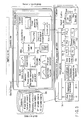
- FIG. 3 is a functional block diagram showing the main part of a HEMS according to the first embodiment.
- various kinds of data are periodically or aperiodically transmitted from a PCS 104, electrical apparatuses 5, a storage battery 102, an FC unit 103, a watt-hour meter 19, and a distribution switchboard 20 of a home 100 to a cloud 300 via a home gateway 7.
- the data can include, for example, the power consumption and the operation state of each of the household electric appliances 5 for every predetermined time, the remaining battery level and the charged and discharged power amounts of the storage battery 102, and the power demand, hot water demand, PV power generation amount, and solar-heated water amount (the amount of hot water supplied by a solar water heater 106) of the home 100.
- the home gateway 7 transmits associated data to the cloud 300.
- "Aperiodic" means transmission at such a timing.
- the operation history of the user of a terminal 105, and the like are also transmitted to the cloud 300. Those data and information are stored in the group of databases DB.
- An estimation unit 300b provided for each customer estimates the power demand, hot water demand, and PV power generation amount for every predetermined time of a day of interest using collected data of the power demand, hot water demand, and PV power generation amount and meteorological data such as a weather forecast.
- the meteorological data is distributed from another server (for example, Meteorological Agency) at several timings a day.
- the estimation calculation may be executed in synchronism with the timing of meteorological data reception.
- the demand can be estimated from meteorological information and past demand data using a neural network (disclosed in Jpn. Pat. Appln. KOKAI Publication No. 06-276681), or estimated by grouping the past demand data of a plurality of customers and forming the average demand variation model of each group (disclosed in Jpn. Pat. Appln. KOKAI Publication No. 2004-112869).
- the hot water demand is estimated from, for example, a calendar (disclosed in Jpn. Pat. Appln. KOKAI Publication No. 2011-83084).
- the PV power generation amount can be estimated based on the statistical correlation between different times in past data or the statistical correlation between different installation positions (disclosed in Jpn. Pat. Appln. KOKAI Publication No. 2011-200040 ).
- the solar-heated hot water can also be estimated by the same method as described above.
- a creation unit 300c provided for each customer executes optimal scheduling concerning operation control of the household electric appliances 5 based on the energy demand, energy supply, energy unit price, control target model 300g, and the like for every predetermined time, calculated by estimation calculation.
- the estimation unit 300b and the creation unit 300c can be implemented as, for example, functional objects dedicated to each customer. That is, the functions of the estimation unit 300b and the creation unit 300c can be provided for each customer.
- Such a form can be obtained by, for example, creating a plurality of threads in the program execution process. This form is advantageous because, for example, security can easily be retained.
- the estimation unit 300b and the creation unit 300c can be implemented as functional objects provided for a plurality of customers. That is, the operations by the estimation unit 300b and the creation unit 300c can be executed for a group of a plurality of customers. This form is advantageous because, for example, the calculation resource can be saved.
- FIG. 4 is a block diagram for explaining the control target model 300g according to the first embodiment.
- the control target model 300g includes a power grid 6, the FC unit 103, the solar water heater 106, the storage battery 102, a PV unit 101, and a load (household electric appliance) 205 as elements.
- the FC unit 103 includes an FC main body 220, an auxiliary boiler 221, a reverse power flow prevention heater 222, and a hot water tank 223 as elements.
- the variables in FIG. 4 are shown below.
- the control target model 300g represents the input/output relationship between the elements and the relational expressions of the input variables or output variables between the elements.
- the control target model 300g can be expressed by equations (1) to (11).
- a gas supply F(t) is indicated as the sum of a supply F FC (t) to the FC and a supply F B (t) to the auxiliary boiler.
- the FC main body 220 is assumed to generate power in an amount P FC (t) with respect to the gas supply F FC (t) and exhausts heat in an amount Q FC (t).
- the input and output characteristics of the FC main body 220 can approximately be expressed by equations (2) and (3). That is, the input and output characteristics of the FC main body 220 are represented by the relationship between the gas supply, the power generation amount, and the exhaust heat amount of the FC main body 220.
- the reverse power flow prevention heater 222 converts surplus power P H (t) into heat in an amount Q H (t) so as to consume it. That is, the reverse power flow prevention heater 222 discards the heat in the amount Q H (t), thereby preventing the surplus power from flowing back to the power grid 6.
- the auxiliary boiler 221 supplies hot water in an amount Q B (t) to cover the shortfall in a hot water supply Q ST (t) from the hot water tank 223 out of the hot water demand.
- a hot water reserve H(t) of the hot water tank 223 increases/decreases in accordance with the exhaust heat Q FC (t) of the FC main body 220, the heat generation amount Q H (t) of the reverse power flow prevention heater 222, and the hot water supply Q ST (t).
- the left-hand side of equation (4) represents the heat amount to the hot water tank 223 on a hot water quantity basis.
- a hot water storage efficiency (residual ratio) r is a coefficient representing the ratio of heat remaining after a decrease by heat dissipation from time (t - 1) to time t.
- the second term of the left-hand side of equation (4) represents the FC waste heat collection amount.
- the third term represents the heat generation amount of the reverse power flow prevention heater. Both the second and third terms are represented by equivalent hot water demand quantities. Note that if the hot water supply line for the solar water heater 106 is connected to the hot water tank 223, Q S (t) is added to the left-hand side of equation (4), and Q S (t) of the right-hand side of equation (11) to be described later is eliminated.
- the right-hand side of equation (4) represents the heat amount from the hot water tank 223 and the remaining heat amount on a hot water quantity basis.
- the first term of the right-hand side represents the hot water reserve of this time
- the second term represents the hot water supply of this time (strictly, the hot water supply from time (t - 1) to time t).
- Inequality (5) represents the constraint of the capacity of the hot water tank 223.
- the storage battery 102 can be expressed as a model that increases/decreases a remaining battery level S(t) based on charged/discharged power P SB (t). Equation (6) represents the power demand and supply balance. P D (t) is the power demand of the home 100, P C (t) is the purchased or sold electricity, and P PV (t) is the power generation amount of the PV unit 101. Inequalities (7) and (8) represent constraints that the reverse power flow from the FC main body 220 and the storage battery 102 is prohibited. Inequality (9) represents the constraint of the capacity of the storage battery 102.
- Inequality (10) represents the constraint that the change in the power generation amount of the FC unit 103 (FC main body 220) with respect to the time is limited within a predetermined range. That is, inequality (10) represents the constraint that the change amount of the power generation amount of the FC main body 220 during the period from the given time (t - 1) to the next time t is limited between -P FC_DOWN that is the lower limit of the decreasing speed of the FC power generation amount and P FC_UP that is the upper limit of the increasing speed of the FC power generation amount.
- a hot water demand QD(t) is covered by the hot water supply Q ST (t) from the hot water tank 223, the hot water supply Q B (t) from the auxiliary boiler, and the hot water supply Q S (t) from the solar water heater 106, as shown in equation (11).
- the creation unit 300c creates the schedule of the power generation P FC (t) of the FC unit 103 and the schedule of the charge and discharge P SB (t) of the storage battery 102 based on the power demand, hot water demand, PV power generation amount, hot water amount from the solar water heater 106, unit prices of electricity and gas, and purchase price of electricity.
- Each schedule is created by, for example, an optimization algorithm such that the heat/electricity balance (energy cost) is minimized under a constraint that surplus power discarded when the storage battery 102 is fully charged is minimized.
- the optimization algorithm for example, a genetic algorithm is usable. The function of the above-described arrangement will be described next.
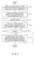
- FIG. 5 is a flowchart showing an example of a processing procedure according to the first embodiment.
- An estimated power demand, estimated hot water demand, estimated PV power generation amount, and the like are necessary for the optimization operation.
- the optimization operation is executed in synchronism with the timings of estimation calculation which is executed several times a day.
- the estimation unit 300b acquires data of the power demand, hot water demand, PV power generation amount, and solar-heated water amount for every predetermined time from a database DB (step S1-1). In this step, past data, for example, data of the same day of a year earlier may be acquired in addition to the current data. Next, the estimation unit 300b estimates the power demand, hot water demand, PV power generation amount, and solar-heated water amount for every predetermined time to calculate the operation schedule (step S1-2).
- the creation unit 300c calculates the schedule of the power generation amount of the FC unit 103 and the schedule of the charge and discharge amount of the storage battery 102 for every predetermined time so as to minimize the heat/electricity balance (step S1-3).
- the calculated schedules are stored in the database DB.
- the system transmits a message signal representing the schedule of the charge and discharge amount of the storage battery 102 or the schedule of the power generation amount of the FC unit 103 to a terminal 105 via an IP network 200.
- the terminal 105 interprets the message signal and displays the various schedules on the interface (step S1-4).
- the routine from the message signal transmission to the display is executed periodically or in response to a request from the user.
- the cloud 300 waits for arrival of a permission message signal representing that execution of the operation schedule is permitted by the user (step S1-5).
- the control unit 300d transmits control information used to control the household electric appliances 5 of the home 100 in accordance with the schedule (created by the creation unit 300c) to the home gateway 7 of the home 100 via the IP network 200 (step S1-6).
- the control information includes, for example, operation/stop designation, an output target value, and the like for charge and discharge of the storage battery 102 and power generation of the FC unit 103.
- the above-described procedure is repeated at the time interval of optimal scheduling.
- the generated control information is transmitted to the home gateway 7 of the home 100.
- the user instructs the system via the user interface 105a to perform or not perform control based on the generated control information.
- the user interface 105a also displays the current state of the solar water heater 106 or estimated status data.
- the temperature of hot water reserve, volume, heat amount, values equivalent to fuel or power necessary for generation, or the use amount thereof may also be displayed.
- FIG. 6 is a conceptual view showing an example of the gene design of a genetic algorithm according to the first embodiment.
- the power generation amount P FC (t) of the FC unit 103 and the charged/discharged power P SB (t) of the storage battery 102 are incorporated into genes.
- the operation schedules of the storage battery 102 and the FC unit 103 of a day are defined as individuals, and a generation includes a plurality of individuals.
- Equation (12) represents a fitness Fit to be maximized.
- the operation schedule can be calculated by performing optimization using Fit as an objective function.
- Equation (13) represents a heat/electricity balance C.
- the fitness Fit represented by equation (12) is the reciprocal of the sum of a monotone increasing function f(C) using the heat/electricity balance C per day as a variable and the cost g(P FC , P SB ) of discontinuity of device operation.
- the heat/electricity balance C may be negative when the PV power generation amount largely exceeds the power demand of the home 100.
- the form of equation (12) is employed.
- the function f(C) > 0 is used.
- the power demand, hot water demand, PV power generation amount, solar water heating amount, unit price of electricity, unit price of gas, and PV purchase price are inserted into the above-described equations, and gene manipulations such as mutation, crossover, and selection are repeated to maximize Fit. It is possible to obtain, by these operations, a series of power generation amounts P FC (t) of the FC unit 103 and a series of charged/discharged powers P SB (t) of the storage battery 102, which can maximize the heat/electricity balance C.
- FIG. 7 is a flowchart showing an example of the procedure of the optimization operation according to the first embodiment.
- a genetic algorithm will be exemplified as the optimization algorithm.
- the processing procedure based on the genetic algorithm will be described below.
- the calculation unit 300c generates n initial individuals.
- the genes of the individuals are, for example, the operation/stop of the FC unit 103, the power generation amount of the FC unit 103, and the charged/discharged power of the storage battery 102 at a time t.
- Gene sequences corresponding to, for example, one day (24 hrs) can be provided.
- Each individual is a set of gene sequences of the FC unit 103 and the storage battery 102.
- the bits of the genes of each individual that does not meet the constraints are inverted, thereby modifying the individual to meet the constraints.
- the loop of step S2-2 indicates processing of repeating the processes of steps S2-3 to S2-6.
- the algorithm operation ends.
- the fitness of each individual and the average fitness of the generation are calculated.
- the average fitness of the generation is compared with the average fitness of two previous generations. If the comparison result is equal to or smaller than an arbitrarily set value ⁇ , the algorithm operation ends.
- the calculation unit 300c discards individuals that do not meet the constraints. Hence, the individuals that do not meet the constraints are selected. If there are a predetermined number of individuals or more, individuals whose fitness is poor (low) are discarded to maintain the number of individuals below the predetermined number.
- the calculation unit 300c multiplies an individual having the best fitness.
- the calculation unit 300c performs pairing at random.
- the pairing is performed in accordance with the percentage (crossover rate) to the total number of individuals.
- a gene locus is selected at random for each pair, and one-point crossover is performed.
- the calculation unit 300c randomly selects individuals of a predetermined percentage (mutation rate) of the total number of individuals and inverts the bits of the genes of arbitrary (randomly decided) gene loci of each individual.
- step S2-3) to step S2-6) is repeated until a condition given by number of generations ⁇ maximum number of generations is met while incrementing the number of generations (loop of step S2-2). If this condition is met, the calculation unit 300c outputs the result (step S2-7), and ends the calculation procedure.
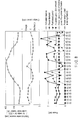
- FIG. 8 is a graph for explaining an effect obtained by the first embodiment.
- FIG. 8 shows examples of the one-day operation schedules of the storage battery 102 and the FC unit 103 which are calculated based on the estimation results of the power demand and hot water demand of one day in the home 100.
- the unit prices of electricity for day and night are assumed, and the unit price of electricity is assumed to be 28 yen/kWh from 7:00 to 23:00 and 9 yen/kWh from 23:00 to 7:00 of the next day.
- FIG. 8 does not assume improvement of the heat/electricity balance by electricity selling, and illustrates the calculation results obtained using only the power demand, hot water demand, and unit prices of electricity and gas.
- the operation schedule of the storage battery 102 defines to perform charge in a time zone where the unit price of electricity is low (0:00 to 6:00) and perform discharge in time zones where the unit price of electricity is high (7:00 to 10:00 and 13:00 to 22:00). Since purchased electricity in the time zones where the unit price of electricity is high decreases, the electricity bill can be reduced.
- the FC unit 103 is operated to the maximum output. In a time zone where the power generation amount exceeds the power demand (12:00 to 14:00), the surplus power is accumulated in the storage battery 102. It is therefore possible to prevent generated power from wastefully being consumed (discarded) by the reverse power flow prevention heater 222 and reduce the gas bill as well.
- the reverse power flow prevention heater 222 remains inoperative for 24 hrs, as can be understood.
- FIG. 8 also shows a graph representing the transition of the total hot water reserve at every time on a calorie basis.
- This graph shows the sum of the amount of hot water of, for example, 45° or more in the hot water tank 223 and the amount of hot water of the same temperature pooled in the solar water heater 106.
- This graph basically indicates the same diurnal variation as that of the PV power generation amount, but changes depending on the operation state of the FC unit 103 and the change in the hot water demand as well.
- the PV power generation amount, power demand, hot water demand, and solar-heated water amount in the home 100 are estimated. Optimization calculation of minimizing the evaluation function under preset constraints is executed, thereby performing energy management to minimize the energy cost (heat and electricity cost). That is, the operation schedule of the FC unit 103 and the charge and discharge schedule of the storage battery 102 are optimized based on the control model that changes the power generation amount of the FC unit 103 and incorporates the solar-heated water amount. This makes it possible to create a schedule that reduces the heat and electricity cost without making the reverse power flow prevention heater 222 wastefully operate.
- the function representing the fitness Fit to be maximized includes the gas rate necessary for the operation of the FC unit 103.
- a schedule that wastefully operates the reverse power flow prevention heater 222 is selected in the process of optimization calculation under a condition that a feasible solution exists.
- a constraint that the change in the power generation amount of the FC unit 103 from the given time (t - 1) to the next time t is limited within the range of -P FC_DOWN (the lower limit of the decreasing speed of the power generation amount of the FC unit 103) and P FC_UP (the upper limit of the increasing speed of the power generation amount of the FC unit 103) is provided.
- step S1-2 and the optimal scheduling of step S1-3 are combined, it is possible to create a demand/supply plan such as the power generation schedule of the FC unit 103 or the charge and discharge schedule of the storage battery 102 in consideration of the overall balance in accordance with the estimated power demand, estimated hot water demand, estimated PV power generation amount, and estimated solar-heated water amount during a relatively long period corresponding to about one day.
- a demand/supply plan such as the power generation schedule of the FC unit 103 or the charge and discharge schedule of the storage battery 102 in consideration of the overall balance in accordance with the estimated power demand, estimated hot water demand, estimated PV power generation amount, and estimated solar-heated water amount during a relatively long period corresponding to about one day.
- surplus power that cannot flow back to the commercial power grid can effectively be used without being wastefully consumed. It is therefore possible to provide an energy management system capable of preventing surplus power from being wastefully consumed, an energy management method, a program, and a server.
- FIG. 9 is a functional block diagram showing the main part of a HEMS according to the second embodiment.
- the same reference numerals as in FIG. 3 denote the same parts in FIG. 9 , and only different parts will be described here.
- the second embodiment assumes a case in which a heat pump water heater (HP) 110 that uses geothermal energy is used in place of the FC unit 103.
- the heat pump water heater 110 is controlled by a control unit 300d based on an optimized operation schedule.
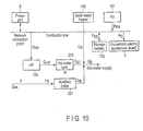
- FIG. 10 is a view for explaining a control target model 300g according to the second embodiment.
- the heat pump water heater 110 replaces the FC main body 220. Since the heat pump water heater 110 has an excellent control response as compared to the FC unit 103, the reverse power flow prevention heater 222 can be removed.
- Expressions (15) to (22) represent the relationships between variables in FIG. 10 .
- the heat pump water heater 110 is incorporated in the optimization calculation. That is, a creation unit 300c executes optimization calculation to minimize the evaluation function based on the estimated power demand, estimated hot water demand in a home 100 and geothermal energy, thereby creating an operation schedule. According to the second embodiment, since the fuel of the FC unit 103 is unnecessary, a larger cost merit can be obtained.
- the present invention is not limited to the above-described embodiments.
- use of a genetic algorithm has been described.
- the genetic algorithm is not the only solution to calculate an operation schedule.
- An optimum operation schedule can be calculated using various other algorithms.
- the present invention is not limited to this, and a water supply route to supply hot water from the solar water heater to the heat pump water heater may be provided. This arrangement is advantageous in winter or in cold climate areas where the insolation is small.
- heat may be collected from water left in the bathtub using a heat exchanger and used to heat hot water from the solar water heater or hot water from the heat pump water heater. That is, the home 100 may be provided with a heat exchanger that exchanges thermal energy between hot water supplied from the water heater and hot water in the bathtub.
- the creation unit 300c creates an operation schedule based on the estimated energy demand, energy supply, and thermal energy.
- a user interface 105a may display external information about heat balance such as solar heat energy and geothermal energy. This allows a user who often pays attention to only electric energy to be aware of the thermal energy.
Landscapes
- Engineering & Computer Science (AREA)
- Physics & Mathematics (AREA)
- General Engineering & Computer Science (AREA)
- Chemical & Material Sciences (AREA)
- Thermal Sciences (AREA)
- Mechanical Engineering (AREA)
- Combustion & Propulsion (AREA)
- Business, Economics & Management (AREA)
- Power Engineering (AREA)
- Economics (AREA)
- Health & Medical Sciences (AREA)
- Strategic Management (AREA)
- Human Resources & Organizations (AREA)
- General Physics & Mathematics (AREA)
- Marketing (AREA)
- Tourism & Hospitality (AREA)
- General Business, Economics & Management (AREA)
- Theoretical Computer Science (AREA)
- Primary Health Care (AREA)
- General Health & Medical Sciences (AREA)
- Public Health (AREA)
- Water Supply & Treatment (AREA)
- Computer Hardware Design (AREA)
- Entrepreneurship & Innovation (AREA)
- Educational Administration (AREA)
- Development Economics (AREA)
- Quality & Reliability (AREA)
- Operations Research (AREA)
- Game Theory and Decision Science (AREA)
- Supply And Distribution Of Alternating Current (AREA)
- Heat-Pump Type And Storage Water Heaters (AREA)
- Charge And Discharge Circuits For Batteries Or The Like (AREA)
- Management, Administration, Business Operations System, And Electronic Commerce (AREA)
- Electromagnetism (AREA)
- Radar, Positioning & Navigation (AREA)
- Automation & Control Theory (AREA)
Applications Claiming Priority (2)
| Application Number | Priority Date | Filing Date | Title |
|---|---|---|---|
| JP2013045471A JP6009976B2 (ja) | 2013-03-07 | 2013-03-07 | エネルギー管理システム、エネルギー管理方法、プログラムおよびサーバ |
| PCT/JP2013/082978 WO2014136341A1 (fr) | 2013-03-07 | 2013-12-09 | Système de gestion d'énergie, procédé de gestion d'énergie, programme, et serveur |
Publications (2)
| Publication Number | Publication Date |
|---|---|
| EP2966748A1 true EP2966748A1 (fr) | 2016-01-13 |
| EP2966748A4 EP2966748A4 (fr) | 2016-11-02 |
Family
ID=51490884
Family Applications (1)
| Application Number | Title | Priority Date | Filing Date |
|---|---|---|---|
| EP13824085.8A Withdrawn EP2966748A4 (fr) | 2013-03-07 | 2013-12-09 | Système de gestion d'énergie, procédé de gestion d'énergie, programme, et serveur |
Country Status (4)
| Country | Link |
|---|---|
| US (1) | US20140257584A1 (fr) |
| EP (1) | EP2966748A4 (fr) |
| JP (1) | JP6009976B2 (fr) |
| WO (1) | WO2014136341A1 (fr) |
Cited By (1)
| Publication number | Priority date | Publication date | Assignee | Title |
|---|---|---|---|---|
| GB2562926B (en) * | 2016-02-26 | 2020-07-15 | Mitsubishi Electric Corp | Hot-water supply system, and control method for water heater |
Families Citing this family (39)
| Publication number | Priority date | Publication date | Assignee | Title |
|---|---|---|---|---|
| US10621683B2 (en) * | 2014-11-05 | 2020-04-14 | Yanmar Co., Ltd. | Control device for optimizing local energy network |
| WO2016120995A1 (fr) * | 2015-01-27 | 2016-08-04 | 三菱電機株式会社 | Dispositif de gestion de fonctionnement de chauffe-eau, système de gestion de fonctionnement de chauffe-eau, et procédé de gestion de fonctionnement de chauffe-eau |
| US10580095B2 (en) * | 2015-03-20 | 2020-03-03 | Accenture Global Solutions Limited | Method and system for water production and distribution control |
| US10601225B2 (en) | 2015-03-30 | 2020-03-24 | Omron Corporation | Management device, management system, control method for management device, and control program |
| WO2016199816A1 (fr) * | 2015-06-08 | 2016-12-15 | 京セラ株式会社 | Dispositif de conversion de puissance, dispositif de gestion de puissance et procédé de gestion de puissance |
| ES2807796T3 (es) | 2015-08-19 | 2021-02-24 | Lsis Co Ltd | Sistema de monitoreo de potencia |
| EP3133374A1 (fr) | 2015-08-19 | 2017-02-22 | LSIS Co., Ltd. | Système de surveillance de puissance |
| CN105337273A (zh) * | 2015-09-18 | 2016-02-17 | 北京德意新能电气有限公司 | 一种适用于智能电网的电能集成互联系统 |
| US10366459B2 (en) * | 2015-10-16 | 2019-07-30 | Andrija Sadikovic | Method and system for aggregation and control of energy grids with distributed energy resources |
| JP6410962B2 (ja) | 2015-11-26 | 2018-10-24 | 三菱電機株式会社 | 配電系統管理装置、計測装置、配電系統管理システムおよび発電量推定方法 |
| JP6143979B1 (ja) * | 2015-12-16 | 2017-06-07 | 三菱電機株式会社 | 電力管理装置 |
| DE102016201105A1 (de) * | 2016-01-26 | 2017-07-27 | Viessmann Werke Gmbh & Co Kg | Vorrichtung und Verfahren für die Steuerung eines Gebäudeenergiesystems |
| DE102016202001A1 (de) * | 2016-02-10 | 2017-08-10 | Bayerische Motoren Werke Aktiengesellschaft | Erkennen von Einstellungsabweichungen an einer Energiemanagementeinrichtung |
| US10198703B2 (en) | 2016-05-10 | 2019-02-05 | Conectric, Llc | Method and system for prioritizing control strategies minimizing real time energy consumption of built environment |
| US10235724B2 (en) * | 2016-06-01 | 2019-03-19 | International Business Machines Corporation | Energy efficient hot water distribution |
| US10908195B2 (en) | 2016-06-15 | 2021-02-02 | Watlow Electric Manufacturing Company | System and method for controlling power to a heater |
| WO2018035348A1 (fr) * | 2016-08-18 | 2018-02-22 | Cornell University | Dispositifs de stockage d'énergie localisés virtuels dans un système de distribution électrique |
| EP3343496A1 (fr) * | 2016-12-28 | 2018-07-04 | Robotina d.o.o. | Procédé et système de gestion d'énergie dans une installation |
| WO2018154727A1 (fr) * | 2017-02-24 | 2018-08-30 | 三菱電機株式会社 | Chauffe-eau, dispositif de commande, système d'alimentation en eau chaude et procédé de fonctionnement de chauffage |
| CN107069911B (zh) * | 2017-02-28 | 2020-08-04 | 浙江蓝特新能源科技股份有限公司 | 一种充电桩系统及其控制方法 |
| US10706375B2 (en) * | 2017-03-29 | 2020-07-07 | Johnson Controls Technology Company | Central plant with asset allocator |
| US11875371B1 (en) | 2017-04-24 | 2024-01-16 | Skyline Products, Inc. | Price optimization system |
| TWI858475B (zh) * | 2017-08-10 | 2024-10-11 | 美商瓦特洛威電子製造公司 | 控制送至加熱器之電力的系統及方法 |
| DE102017118958A1 (de) * | 2017-08-18 | 2019-02-21 | Christian Schuch | Energiemanagementsystem-Vorrichtung und ein Energiemanagementsystem-Verfahren |
| CN109507957B (zh) * | 2017-09-15 | 2022-04-01 | 进金生实业股份有限公司 | 用于水处理产业的云端智能节电系统 |
| DE102017221145A1 (de) * | 2017-11-27 | 2019-05-29 | Siemens Aktiengesellschaft | Energieversorgungsnetzwerke und -verfahren |
| CN108270244B (zh) * | 2018-01-26 | 2022-08-09 | 国网辽宁省电力有限公司 | 一种新能源电力系统在多种调控域运行方式下调度方法 |
| JP6414870B1 (ja) * | 2018-04-18 | 2018-10-31 | 松尾建設株式会社 | 逆潮流防止型自家消費用再エネ発電蓄電制御装置 |
| CN108959172A (zh) * | 2018-05-30 | 2018-12-07 | 新奥泛能网络科技有限公司 | 燃气蒸汽锅炉的供能成本计算方法及装置 |
| CN109839876A (zh) * | 2019-03-01 | 2019-06-04 | 苏州洪昇新能源科技有限公司 | 一种企业建筑节能管控系统 |
| CL2019000938A1 (es) * | 2019-04-08 | 2019-10-18 | Univ Adolfo Ibanez | Equipo, sistema y método para administrar óptimamemte la energía en una red de uso domiciliario e industrial. |
| JP7345408B2 (ja) * | 2020-01-29 | 2023-09-15 | 株式会社日立製作所 | エネルギー管理システムおよびエネルギー管理方法 |
| JP7588543B2 (ja) * | 2021-04-08 | 2024-11-22 | 大阪瓦斯株式会社 | 管理サーバ |
| GB2608872B (en) * | 2021-10-27 | 2023-07-12 | Digital Heat Ltd | Electric fluid heater |
| CN114110716B (zh) * | 2021-11-24 | 2023-06-02 | 新疆天池能源有限责任公司 | 一种热电机组的运行能效监测控制系统、方法、计算机设备及存储介质 |
| CN115848196B (zh) * | 2022-12-07 | 2024-01-05 | 南通国轩新能源科技有限公司 | 基于动态需求和新能源消纳的电动汽车有序充电引导方法 |
| CN116306050B (zh) * | 2023-05-23 | 2023-08-18 | 广东电网有限责任公司阳江供电局 | 储能配置确定方法、装置及电子设备 |
| KR102877991B1 (ko) * | 2024-10-10 | 2025-10-30 | 주식회사 제이에스이앤씨 | 시계열 예측을 위한 딥러닝 기반의 넷제로 에너지 구현을 위한 스마트 에너지 관리 시스템 |
| CN120341965B (zh) * | 2025-04-25 | 2026-01-27 | 广东格绿朗节能科技有限公司 | 一种光储充一体化阳光房系统及控制方法 |
Family Cites Families (22)
| Publication number | Priority date | Publication date | Assignee | Title |
|---|---|---|---|---|
| JP3302081B2 (ja) | 1993-03-23 | 2002-07-15 | 北陸電力株式会社 | 電力需要量予測装置 |
| JP2002048005A (ja) | 2000-07-31 | 2002-02-15 | Osaka Gas Co Ltd | コージェネレーションシステム |
| US20090210081A1 (en) * | 2001-08-10 | 2009-08-20 | Rockwell Automation Technologies, Inc. | System and method for dynamic multi-objective optimization of machine selection, integration and utilization |
| JP4025157B2 (ja) | 2002-09-13 | 2007-12-19 | 株式会社東芝 | 電力需要予測システム |
| JP2004312798A (ja) * | 2003-04-02 | 2004-11-04 | Toshiba Corp | 分散エネルギーシステムおよびその制御方法 |
| JP2005086953A (ja) * | 2003-09-10 | 2005-03-31 | Nippon Telegr & Teleph Corp <Ntt> | エネルギー需給制御方法及び装置 |
| JP2005304118A (ja) | 2004-04-07 | 2005-10-27 | Nippon Telegr & Teleph Corp <Ntt> | 分散型エネルギーシステムの制御装置および制御方法 |
| JP4245583B2 (ja) * | 2005-04-15 | 2009-03-25 | 日本電信電話株式会社 | 分散型エネルギーシステムの制御装置、制御方法、プログラム、および記録媒体 |
| JP2008083971A (ja) * | 2006-09-27 | 2008-04-10 | Toyohashi Univ Of Technology | 太陽・風力発電/コージェネレーション装置からなるシステムのシミュレーション方法 |
| JP5092909B2 (ja) | 2008-06-03 | 2012-12-05 | 富士通モバイルコミュニケーションズ株式会社 | 携帯端末 |
| JP2010273407A (ja) | 2009-05-19 | 2010-12-02 | Osaka Gas Co Ltd | エネルギー供給システム |
| JP5465949B2 (ja) * | 2009-08-07 | 2014-04-09 | 本田技研工業株式会社 | 電力供給システム |
| JP5466911B2 (ja) | 2009-10-05 | 2014-04-09 | パナソニック株式会社 | 電力供給システム及び電力供給システムの制御装置 |
| US20110106327A1 (en) * | 2009-11-05 | 2011-05-05 | General Electric Company | Energy optimization method |
| JP2011217590A (ja) * | 2010-03-18 | 2011-10-27 | Sanyo Electric Co Ltd | 空調システム |
| CN102349213A (zh) * | 2010-01-12 | 2012-02-08 | 松下电器产业株式会社 | 供需控制装置、供需控制方法及供需控制系统 |
| WO2011105070A1 (fr) * | 2010-02-25 | 2011-09-01 | パナソニック株式会社 | Appareil et procédé de régulation par l'offre et la demande, et programme associé |
| JP2011181377A (ja) | 2010-03-02 | 2011-09-15 | Toshiba Fuel Cell Power Systems Corp | 燃料電池システム |
| JP5606114B2 (ja) | 2010-03-19 | 2014-10-15 | 株式会社東芝 | 発電量予測装置、予測方法及び予測プログラム |
| JP5508141B2 (ja) * | 2010-05-27 | 2014-05-28 | 大阪瓦斯株式会社 | エネルギー消費量表示システム |
| JP5660863B2 (ja) | 2010-11-22 | 2015-01-28 | 京セラ株式会社 | 制御装置及び制御方法 |
| WO2014034391A1 (fr) * | 2012-09-03 | 2014-03-06 | 株式会社 東芝 | Système de régulation d'énergie, serveur, procédé de régulation d'énergie et support d'informations |
-
2013
- 2013-03-07 JP JP2013045471A patent/JP6009976B2/ja not_active Expired - Fee Related
- 2013-12-09 EP EP13824085.8A patent/EP2966748A4/fr not_active Withdrawn
- 2013-12-09 WO PCT/JP2013/082978 patent/WO2014136341A1/fr not_active Ceased
-
2014
- 2014-01-31 US US14/170,112 patent/US20140257584A1/en not_active Abandoned
Cited By (1)
| Publication number | Priority date | Publication date | Assignee | Title |
|---|---|---|---|---|
| GB2562926B (en) * | 2016-02-26 | 2020-07-15 | Mitsubishi Electric Corp | Hot-water supply system, and control method for water heater |
Also Published As
| Publication number | Publication date |
|---|---|
| EP2966748A4 (fr) | 2016-11-02 |
| US20140257584A1 (en) | 2014-09-11 |
| WO2014136341A1 (fr) | 2014-09-12 |
| JP6009976B2 (ja) | 2016-10-19 |
| JP2014176161A (ja) | 2014-09-22 |
Similar Documents
| Publication | Publication Date | Title |
|---|---|---|
| EP2966748A1 (fr) | Système de gestion d'énergie, procédé de gestion d'énergie, programme, et serveur | |
| US9824409B2 (en) | Energy management system, server, energy management method, and storage medium | |
| EP2953230A1 (fr) | Système de gestion d'énergie, procédé de gestion d'énergie, programme et serveur | |
| US11010846B2 (en) | Building energy storage system with multiple demand charge cost optimization | |
| JP5921390B2 (ja) | エネルギー管理システム、エネルギー管理方法、プログラムおよびサーバ装置 | |
| Zakariazadeh et al. | Smart microgrid energy and reserve scheduling with demand response using stochastic optimization | |
| JP6178045B2 (ja) | エネルギー管理システム、エネルギー管理方法、プログラムおよびサーバ装置 | |
| US20140257585A1 (en) | Energy management system, energy management method, and medium | |
| JP6429200B2 (ja) | 電力系統を運転するための方法およびシステム | |
| CN102436602B (zh) | 能量管理系统以及能量管理方法 | |
| EP2966611A1 (fr) | Système et procédé de gestion d'énergie, programme et serveur | |
| JP2017229233A (ja) | エネルギー管理システム、エネルギー管理方法、プログラム、サーバおよびクライアント装置 | |
| Wu et al. | Impact of model predictive control-enabled home energy management on large-scale distribution systems with photovoltaics | |
| JP2014096866A (ja) | エネルギー管理システム、エネルギー管理方法、プログラムおよびサーバ装置 | |
| US20120215371A1 (en) | Method of controlling network system | |
| Pedrasa et al. | Improved energy services provision through the intelligent control of distributed energy resources | |
| Elkazaz et al. | Operation optimization of distributed generation using artificial intelligent techniques | |
| Wang et al. | Tri-level hybrid interval-stochastic optimal scheduling for flexible residential loads under GAN-assisted multiple uncertainties | |
| Singabhattu et al. | Distributed energy resources optimization for demand response using MILP | |
| Olowolaju et al. | Customer centric price-based energy flexibility estimation for thermostatically-controlled loads | |
| Pereira et al. | Understanding the role of solar PV and battery energy storage in a snack bar: a case study in Madeira Island | |
| Elkazaz et al. | Optimizing distributed generation operation for residential application based on automated systems | |
| Wang et al. | Two-stage cooperative operation strategy for home management systems with smart appliances | |
| Yao et al. | Tackling the photovoltaic integration challenge in the distribution network with deferrable load | |
| Laour et al. | Optimal operating strategy of a net-zero electricity solar photovoltaic building for a sustainable energy future: a case study in northern Algeria |
Legal Events
| Date | Code | Title | Description |
|---|---|---|---|
| PUAI | Public reference made under article 153(3) epc to a published international application that has entered the european phase |
Free format text: ORIGINAL CODE: 0009012 |
|
| 17P | Request for examination filed |
Effective date: 20140203 |
|
| AK | Designated contracting states |
Kind code of ref document: A1 Designated state(s): AL AT BE BG CH CY CZ DE DK EE ES FI FR GB GR HR HU IE IS IT LI LT LU LV MC MK MT NL NO PL PT RO RS SE SI SK SM TR |
|
| AX | Request for extension of the european patent |
Extension state: BA ME |
|
| DAX | Request for extension of the european patent (deleted) | ||
| A4 | Supplementary search report drawn up and despatched |
Effective date: 20160929 |
|
| RIC1 | Information provided on ipc code assigned before grant |
Ipc: H02J 3/38 20060101ALI20160923BHEP Ipc: F24H 1/00 20060101ALI20160923BHEP Ipc: G06Q 50/06 20120101ALI20160923BHEP Ipc: H02J 3/00 20060101ALI20160923BHEP Ipc: H02J 3/46 20060101AFI20160923BHEP Ipc: H02J 3/14 20060101ALI20160923BHEP Ipc: F24D 19/10 20060101ALI20160923BHEP |
|
| STAA | Information on the status of an ep patent application or granted ep patent |
Free format text: STATUS: EXAMINATION IS IN PROGRESS |
|
| 17Q | First examination report despatched |
Effective date: 20170908 |
|
| STAA | Information on the status of an ep patent application or granted ep patent |
Free format text: STATUS: THE APPLICATION IS DEEMED TO BE WITHDRAWN |
|
| 18D | Application deemed to be withdrawn |
Effective date: 20180828 |