EP2966933A1 - Elektrische heizpatrone - Google Patents
Elektrische heizpatrone Download PDFInfo
- Publication number
- EP2966933A1 EP2966933A1 EP15176245.7A EP15176245A EP2966933A1 EP 2966933 A1 EP2966933 A1 EP 2966933A1 EP 15176245 A EP15176245 A EP 15176245A EP 2966933 A1 EP2966933 A1 EP 2966933A1
- Authority
- EP
- European Patent Office
- Prior art keywords
- electric heating
- cross
- connecting wire
- channel
- winding body
- Prior art date
- Legal status (The legal status is an assumption and is not a legal conclusion. Google has not performed a legal analysis and makes no representation as to the accuracy of the status listed.)
- Granted
Links
Images

Classifications
-
- H—ELECTRICITY
- H05—ELECTRIC TECHNIQUES NOT OTHERWISE PROVIDED FOR
- H05B—ELECTRIC HEATING; ELECTRIC LIGHT SOURCES NOT OTHERWISE PROVIDED FOR; CIRCUIT ARRANGEMENTS FOR ELECTRIC LIGHT SOURCES, IN GENERAL
- H05B3/00—Ohmic-resistance heating
- H05B3/0014—Devices wherein the heating current flows through particular resistances
-
- H—ELECTRICITY
- H01—ELECTRIC ELEMENTS
- H01F—MAGNETS; INDUCTANCES; TRANSFORMERS; SELECTION OF MATERIALS FOR THEIR MAGNETIC PROPERTIES
- H01F27/00—Details of transformers or inductances, in general
- H01F27/28—Coils; Windings; Conductive connections
- H01F27/2823—Wires
-
- H—ELECTRICITY
- H01—ELECTRIC ELEMENTS
- H01R—ELECTRICALLY-CONDUCTIVE CONNECTIONS; STRUCTURAL ASSOCIATIONS OF A PLURALITY OF MUTUALLY-INSULATED ELECTRICAL CONNECTING ELEMENTS; COUPLING DEVICES; CURRENT COLLECTORS
- H01R24/00—Two-part coupling devices, or either of their cooperating parts, characterised by their overall structure
- H01R24/38—Two-part coupling devices, or either of their cooperating parts, characterised by their overall structure having concentrically or coaxially arranged contacts
-
- H—ELECTRICITY
- H01—ELECTRIC ELEMENTS
- H01R—ELECTRICALLY-CONDUCTIVE CONNECTIONS; STRUCTURAL ASSOCIATIONS OF A PLURALITY OF MUTUALLY-INSULATED ELECTRICAL CONNECTING ELEMENTS; COUPLING DEVICES; CURRENT COLLECTORS
- H01R4/00—Electrically-conductive connections between two or more conductive members in direct contact, i.e. touching one another; Means for effecting or maintaining such contact; Electrically-conductive connections having two or more spaced connecting locations for conductors and using contact members penetrating insulation
- H01R4/10—Electrically-conductive connections between two or more conductive members in direct contact, i.e. touching one another; Means for effecting or maintaining such contact; Electrically-conductive connections having two or more spaced connecting locations for conductors and using contact members penetrating insulation effected solely by twisting, wrapping, bending, crimping, or other permanent deformation
- H01R4/18—Electrically-conductive connections between two or more conductive members in direct contact, i.e. touching one another; Means for effecting or maintaining such contact; Electrically-conductive connections having two or more spaced connecting locations for conductors and using contact members penetrating insulation effected solely by twisting, wrapping, bending, crimping, or other permanent deformation by crimping
-
- H—ELECTRICITY
- H01—ELECTRIC ELEMENTS
- H01R—ELECTRICALLY-CONDUCTIVE CONNECTIONS; STRUCTURAL ASSOCIATIONS OF A PLURALITY OF MUTUALLY-INSULATED ELECTRICAL CONNECTING ELEMENTS; COUPLING DEVICES; CURRENT COLLECTORS
- H01R43/00—Apparatus or processes specially adapted for manufacturing, assembling, maintaining, or repairing of line connectors or current collectors or for joining electric conductors
- H01R43/02—Apparatus or processes specially adapted for manufacturing, assembling, maintaining, or repairing of line connectors or current collectors or for joining electric conductors for soldered or welded connections
-
- H—ELECTRICITY
- H01—ELECTRIC ELEMENTS
- H01R—ELECTRICALLY-CONDUCTIVE CONNECTIONS; STRUCTURAL ASSOCIATIONS OF A PLURALITY OF MUTUALLY-INSULATED ELECTRICAL CONNECTING ELEMENTS; COUPLING DEVICES; CURRENT COLLECTORS
- H01R43/00—Apparatus or processes specially adapted for manufacturing, assembling, maintaining, or repairing of line connectors or current collectors or for joining electric conductors
- H01R43/04—Apparatus or processes specially adapted for manufacturing, assembling, maintaining, or repairing of line connectors or current collectors or for joining electric conductors for forming connections by deformation, e.g. crimping tool
- H01R43/048—Crimping apparatus or processes
-
- H—ELECTRICITY
- H01—ELECTRIC ELEMENTS
- H01R—ELECTRICALLY-CONDUCTIVE CONNECTIONS; STRUCTURAL ASSOCIATIONS OF A PLURALITY OF MUTUALLY-INSULATED ELECTRICAL CONNECTING ELEMENTS; COUPLING DEVICES; CURRENT COLLECTORS
- H01R43/00—Apparatus or processes specially adapted for manufacturing, assembling, maintaining, or repairing of line connectors or current collectors or for joining electric conductors
- H01R43/16—Apparatus or processes specially adapted for manufacturing, assembling, maintaining, or repairing of line connectors or current collectors or for joining electric conductors for manufacturing contact members, e.g. by punching and by bending
-
- H—ELECTRICITY
- H01—ELECTRIC ELEMENTS
- H01R—ELECTRICALLY-CONDUCTIVE CONNECTIONS; STRUCTURAL ASSOCIATIONS OF A PLURALITY OF MUTUALLY-INSULATED ELECTRICAL CONNECTING ELEMENTS; COUPLING DEVICES; CURRENT COLLECTORS
- H01R43/00—Apparatus or processes specially adapted for manufacturing, assembling, maintaining, or repairing of line connectors or current collectors or for joining electric conductors
- H01R43/20—Apparatus or processes specially adapted for manufacturing, assembling, maintaining, or repairing of line connectors or current collectors or for joining electric conductors for assembling or disassembling contact members with insulating base, case or sleeve
- H01R43/24—Assembling by moulding on contact members
-
- H—ELECTRICITY
- H05—ELECTRIC TECHNIQUES NOT OTHERWISE PROVIDED FOR
- H05B—ELECTRIC HEATING; ELECTRIC LIGHT SOURCES NOT OTHERWISE PROVIDED FOR; CIRCUIT ARRANGEMENTS FOR ELECTRIC LIGHT SOURCES, IN GENERAL
- H05B3/00—Ohmic-resistance heating
- H05B3/02—Details
- H05B3/06—Heater elements structurally combined with coupling elements or holders
-
- H—ELECTRICITY
- H05—ELECTRIC TECHNIQUES NOT OTHERWISE PROVIDED FOR
- H05B—ELECTRIC HEATING; ELECTRIC LIGHT SOURCES NOT OTHERWISE PROVIDED FOR; CIRCUIT ARRANGEMENTS FOR ELECTRIC LIGHT SOURCES, IN GENERAL
- H05B3/00—Ohmic-resistance heating
- H05B3/02—Details
- H05B3/06—Heater elements structurally combined with coupling elements or holders
- H05B3/08—Heater elements structurally combined with coupling elements or holders having electric connections specially adapted for high temperatures
-
- H—ELECTRICITY
- H05—ELECTRIC TECHNIQUES NOT OTHERWISE PROVIDED FOR
- H05B—ELECTRIC HEATING; ELECTRIC LIGHT SOURCES NOT OTHERWISE PROVIDED FOR; CIRCUIT ARRANGEMENTS FOR ELECTRIC LIGHT SOURCES, IN GENERAL
- H05B3/00—Ohmic-resistance heating
- H05B3/40—Heating elements having the shape of rods or tubes
- H05B3/42—Heating elements having the shape of rods or tubes non-flexible
-
- H—ELECTRICITY
- H05—ELECTRIC TECHNIQUES NOT OTHERWISE PROVIDED FOR
- H05B—ELECTRIC HEATING; ELECTRIC LIGHT SOURCES NOT OTHERWISE PROVIDED FOR; CIRCUIT ARRANGEMENTS FOR ELECTRIC LIGHT SOURCES, IN GENERAL
- H05B3/00—Ohmic-resistance heating
- H05B3/40—Heating elements having the shape of rods or tubes
- H05B3/42—Heating elements having the shape of rods or tubes non-flexible
- H05B3/48—Heating elements having the shape of rods or tubes non-flexible heating conductor embedded in insulating material
-
- H—ELECTRICITY
- H05—ELECTRIC TECHNIQUES NOT OTHERWISE PROVIDED FOR
- H05B—ELECTRIC HEATING; ELECTRIC LIGHT SOURCES NOT OTHERWISE PROVIDED FOR; CIRCUIT ARRANGEMENTS FOR ELECTRIC LIGHT SOURCES, IN GENERAL
- H05B3/00—Ohmic-resistance heating
- H05B3/40—Heating elements having the shape of rods or tubes
- H05B3/42—Heating elements having the shape of rods or tubes non-flexible
- H05B3/48—Heating elements having the shape of rods or tubes non-flexible heating conductor embedded in insulating material
- H05B3/50—Heating elements having the shape of rods or tubes non-flexible heating conductor embedded in insulating material heating conductor arranged in metal tubes, the radiating surface having heat-conducting fins
-
- H—ELECTRICITY
- H05—ELECTRIC TECHNIQUES NOT OTHERWISE PROVIDED FOR
- H05B—ELECTRIC HEATING; ELECTRIC LIGHT SOURCES NOT OTHERWISE PROVIDED FOR; CIRCUIT ARRANGEMENTS FOR ELECTRIC LIGHT SOURCES, IN GENERAL
- H05B3/00—Ohmic-resistance heating
- H05B3/40—Heating elements having the shape of rods or tubes
- H05B3/42—Heating elements having the shape of rods or tubes non-flexible
- H05B3/48—Heating elements having the shape of rods or tubes non-flexible heating conductor embedded in insulating material
- H05B3/52—Apparatus or processes for filling or compressing insulating material in tubes
-
- H—ELECTRICITY
- H01—ELECTRIC ELEMENTS
- H01R—ELECTRICALLY-CONDUCTIVE CONNECTIONS; STRUCTURAL ASSOCIATIONS OF A PLURALITY OF MUTUALLY-INSULATED ELECTRICAL CONNECTING ELEMENTS; COUPLING DEVICES; CURRENT COLLECTORS
- H01R2103/00—Two poles
-
- H—ELECTRICITY
- H05—ELECTRIC TECHNIQUES NOT OTHERWISE PROVIDED FOR
- H05B—ELECTRIC HEATING; ELECTRIC LIGHT SOURCES NOT OTHERWISE PROVIDED FOR; CIRCUIT ARRANGEMENTS FOR ELECTRIC LIGHT SOURCES, IN GENERAL
- H05B2203/00—Aspects relating to Ohmic resistive heating covered by group H05B3/00
- H05B2203/012—Heaters using non- flexible resistive rods or tubes not provided for in H05B3/42
-
- H—ELECTRICITY
- H05—ELECTRIC TECHNIQUES NOT OTHERWISE PROVIDED FOR
- H05B—ELECTRIC HEATING; ELECTRIC LIGHT SOURCES NOT OTHERWISE PROVIDED FOR; CIRCUIT ARRANGEMENTS FOR ELECTRIC LIGHT SOURCES, IN GENERAL
- H05B2203/00—Aspects relating to Ohmic resistive heating covered by group H05B3/00
- H05B2203/014—Heaters using resistive wires or cables not provided for in H05B3/54
-
- H—ELECTRICITY
- H05—ELECTRIC TECHNIQUES NOT OTHERWISE PROVIDED FOR
- H05B—ELECTRIC HEATING; ELECTRIC LIGHT SOURCES NOT OTHERWISE PROVIDED FOR; CIRCUIT ARRANGEMENTS FOR ELECTRIC LIGHT SOURCES, IN GENERAL
- H05B2203/00—Aspects relating to Ohmic resistive heating covered by group H05B3/00
- H05B2203/016—Heaters using particular connecting means
-
- H—ELECTRICITY
- H05—ELECTRIC TECHNIQUES NOT OTHERWISE PROVIDED FOR
- H05B—ELECTRIC HEATING; ELECTRIC LIGHT SOURCES NOT OTHERWISE PROVIDED FOR; CIRCUIT ARRANGEMENTS FOR ELECTRIC LIGHT SOURCES, IN GENERAL
- H05B2203/00—Aspects relating to Ohmic resistive heating covered by group H05B3/00
- H05B2203/017—Manufacturing methods or apparatus for heaters
Definitions
- the invention relates to an electric heater with the features of claim 1 and a method for producing such a heater.
- electrical heating devices include, for example, heating cartridges that are used, inter alia, for heating a wide variety of components in the automotive industry.
- Known heating cartridges have an often tubular metal shell, which defines a pipe interior.
- an electrical heating element is arranged, which is usually designed as Bankdrahtwicklung, which may be arranged in particular on a winding body and is advantageously electrically insulated from the metal shell, in particular by a Isolierstoffhellung-.
- connecting wires which are in electrical contact with the heating wire winding, can be led out of the metal jacket.
- An example of this basic structure for example, the DE 20 2011 105 348 U1 or the DE 20 265 960 U1 ,
- the heating cartridges known from the prior art prove in practice, especially in heating cartridges, where high currents are necessary to provide the desired heating power and thereby determine the geometry of the connecting wire, as not ideal.
- the problem in this case to ensure a safe and reproducible electrical contact between the electric heating element and the connecting wire.
- the object of the invention is therefore to provide a particular with regard to this electrical contact improved heating cartridge.
- the electric heating element according to the invention comprises at least one connecting wire and at least one electrical heating element wound at least in sections on a wound body, for example made of ceramic, wherein the winding body has at least one channel in which at least one end of an electric heating element wound on the winding body is accommodated.
- a wound body for example made of ceramic
- the winding body has at least one channel in which at least one end of an electric heating element wound on the winding body is accommodated.
- an at least partially closed channel which is separated in the thus executed sections in each direction perpendicular to the direction of the channel by a wall from the environment, as e.g. can be generated by a hole in the winding body.
- said components are disposed within a metal shell and embedded in an insulating layer, which in particular prevents an unwanted short circuit to the metal shell.
- the leads can also be configured differently and a two-sided or one-sided connection of the electric immersion heater by means of connecting wires is possible ,
- the connecting wires can also be bent outward or angled.
- the connecting wire has along its course at least one point or a portion at which the cross-sectional geometry of the connecting wire of the cross-sectional geometry of the connecting wire at least with respect to the contour of the cross-section of the connecting wire, in other words with respect to the contour of the local direction of the Further, a section of the at least one connecting wire is received in the channel, so that in the channel, an electrical contact between the received end of the electric heating element and the recorded portion of the connecting wire.
- contours that can be converted into one another by means of a geometric similarity illustration are to be understood as different contours.
- the invention makes use of the knowledge of the inventor that the requirements for the cross-sectional geometry of the lead wire, resulting from the adaptation to the use of a particular current, for example, a given cross-sectional area, which is necessary to unwanted heating of the electric immersion heater in a unheated section to avoid, within the bobbin no inventory have more.
- a higher current load, which is usually to be avoided, is acceptable there because, on the one hand, heating power is usually to be provided on the one hand, and the winding body is dimensioned and configured in any case such that local overheating is also ruled out.
- a portion of the lead wire may be configured to meet the conductor geometry requirements outside the coil body while introducing a much thinner portion into the coil body channel that defines the maximum cross-sectional area of that portion, and there the desired electrical contact to the electric heating element, in particular a heating or resistance wire, with which the winding body is wound, in particular produces a radial compression of the electric heating cartridge, resulting in a very good and intimate electrical contact.
- the portion of the connecting wire accommodated in the channel of the wound body has a smaller cross-sectional area than at least one other portion of the connecting wire.
- the electric heating cartridge is pressed or compacted, in particular highly compressed.
- the connecting wire has at least one cross-sectional area with a rounded contour and / or at least a cross-sectional area having a contour which is angular. It is particularly preferred if the region of the connecting wire, which is received in the channel of the winding body, has cross-sectional surfaces with a rounded contour. In this way, for example, a possible risk of breakage for the winding body, but also a risk of damage to the electric heating element by acting thereon edge of the connecting wire during pressing can be significantly reduced, while in the region of the connecting wire, which runs outside the winding body, an optimal space- or land use is possible.
- the connecting wire in particular in its section extending outside the winding body, is at least partially surrounded by an insulating layer, which in particular is made of PTFE, PFA, FEP, polyimide, silicone, rubber, glass silk or a plastic can.
- an insulating layer which in particular is made of PTFE, PFA, FEP, polyimide, silicone, rubber, glass silk or a plastic can.
- the length of the portion of the connecting wire, which is received in the channel of the winding body is limited by a stop. In this way, an exact and reproducible insertion depth of the inserted into the channel of the winding body portion of the lead wire can be ensured, which unifies the contact between the lead wire and electric heating element and thus homogenized the properties of the electric immersion heater within a production series or a model.
- the cross-sectional area of the connecting wire has a recess on at least one side, which is preferably adapted to the cross-section of the electrical heating element, the electrical contact between connecting wire and electrical heating element can be improved even further and further standardized, so that the property fluctuations of the electric heating cartridges of a given type can be further reduced. It is particularly preferred if the recess is produced by stamping or material removal by a shaping process.
- the portion of the connecting wire not received in the channel of the winding body runs at a smaller distance from a metal jacket of the electric heating cartridge than the portion of the connecting wire accommodated in the channel of the winding body, it is possible to remove the outside of the winding body optimal space available to adapt the running there sections of the connecting wires, so as to allow the highest possible current flow.
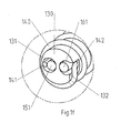
- FIGS. 1a to 1f show an embodiment of an electric heating cartridge 100.
- the electric heating cartridge 100 has a hollow cylindrical metal shell 110 with bottom 111 in this example.
- a winding body 130 is arranged, which with a electric heating element 140, for example a heating wire, is wrapped. How to be particularly good in Figure 1c detects, the winding body 130 has two channels 131,132, in each of which one end 141,142 of the electric heating element 140 is received.
- the electric heating cartridge 100 has two connecting wires 150,160, which, like the Figures 1b, 1c and 1e particularly clearly show, each having a cylindrical first portion 151,161 and a cylindrical second portion 152,162, which merge into each other in a transition region 153,163.
- the cross section of the first section 151, 161 is smaller than the cross section of the second section 152, 162 so that the connection wires 150, 160 each have a location or a section at which the cross sectional geometry of the connection wire is different from the cross sectional geometry of the connection wire, at least with respect to the contour of the cross section of the connection wire differs at another point or another section.
- the cylinder axis of the first section 151, 161 runs parallel but offset from the cylinder axis of the second section 152, 162 of the connecting wires 150, 160, and the connection-side end section of the second section 152, 162 is surrounded in each case by an insulating layer 154, 164.
- the interior 120 of the electric immersion heater 100 is closed with a closure piece 170, the holes 171,172 for receiving the transition region 153,163 and a portion of the second portion 152,162 of the leads 150,160, and filled with an insulating material, not shown, typically a magnesium oxide granules.
- an insulating material typically a magnesium oxide granules.
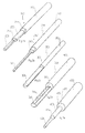
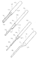
- FIGS. 2a to 2i show in each case differently shaped forms of connecting wires 250,260,350,360,450,460,550, 560,150.
- connection wire 250 has a first portion 251 which is cuboidal and a second portion 252 which is cylindrical and has a larger cross-sectional area.
- a third section 253 is provided with an oval cross-section, the cross-sectional area of its size and outer contour forth between the cross-sectional area of the first portion 251 and the cross-sectional area of the second portion 252.
- a transitional region 254, 255 in which the respective cross sections merge continuously into one another.
- Such a configuration with three sections 251, 252, 253 is particularly suitable when inside the tubular section Mantels the heating element, an unheated section should be present and the cross section of the jacket of the heating cartridge is not sufficient to accommodate the largest cross sections of the connecting wires.
- connection wire 260 has a first portion 261 which is cuboidal and a second portion 262 which is cylindrical and has a larger cross-sectional area. Between the sections 261, 262 a transition region 264 is provided, in which the respective cross sections merge continuously into one another. At the transition region 264 facing the end of the first portion 261, a stop 263 is formed.
- the lead wire 350 has a first portion 351, which has a semicircular cross-section and a second portion 352 which is cylindrical and has the cross-section corresponding to the semicircular cross-section of the first portion 351, equal in terms of its radius full circle, which logically he then also a has larger cross-sectional area.
- the first section 351 merges directly into the second section 352, so that the sudden change in cross section at the transition point can act as a stop 353.
- the lead wire 360 according to Figure 2d has a first portion 361, which has a circular-segment-shaped cross-section and, for example, from a section with a circular segment-shaped cross-section through the provision of a recess 364 by punching or material removal can be generated.
- the lead wire 360 has a second portion 362 which is cylindrical in shape and as a cross section to circular ring segment-shaped cross-section of the first portion 361 corresponding, equal in terms of its radius of full circle having, whereby it logically then also has a larger cross-sectional area.
- the first section 361 merges directly into the second section 362, so that the abrupt change in cross section at the transition point can act as a stop 363.
- connection wire 450 has a first portion 451 which is cylindrically shaped and a second portion 452 which is also cylindrical in shape and has a larger cross-sectional area.
- a third, likewise cylindrical section 453 is provided, whose cross-sectional area of its size and outer contour lies between the cross-sectional area of the first section 451 and the cross-sectional area of the second section 452.
- a transition region 454, 455 is provided in each case, in which the respective cross sections merge continuously into one another.
- the lead wire 460 according to FIG. 2f has a first portion 461, whose cross-section is L-shaped, and for example, from a section with cuboidal cross-section by the provision of a recess 464 by punching or material removal can be generated. Further, the lead wire 460 has a second portion 462 which is cylindrical in shape and has a larger cross-sectional area. The first section 461 transitions directly into the second section 462, so that the sudden change in cross section at the transition point can act as a stop 463.
- the connecting wire 550 has a first portion 551, which is cuboidal and a second portion 552 which is cylindrical and has a larger cross-sectional area. Between the sections 551, 552, a third section 553 is provided, the cross-sectional area of which differs from the cross-sectional area of the first section 551 in only one dimension, specifically the width, and in which three of the side boundary surfaces of the first section 551 and the third section merge continuously, while the fourth side boundary surface and jump over, so that a stop 554 is formed. In contrast, between the third portion 553 and the second portion 552, there is provided a transition portion 555 in which the respective cross sections continuously merge.
- the lead wire 560 according to FIG. 2h has a first portion 561 which is cylindrically shaped and a second portion 562 which is also cylindrical in shape and has a larger cross-sectional area. Between the first section 561 and the second section 562, a third section 563 with a cuboidal cross-section is provided, whose end facing the second section 562 is widened symmetrically to a stop 564. Between the sections 561, 562, 563 a transitional area 565, 566 is provided in each case, in which the respective cross sections merge continuously into one another.
- the lead wire 150 which is in FIG. 2i is in terms of its design, the connecting wires in the FIGS. 1a to 1f Connection wire 150 shown, so refer to their description to avoid repetition.
Landscapes
- Engineering & Computer Science (AREA)
- Manufacturing & Machinery (AREA)
- Power Engineering (AREA)
- Resistance Heating (AREA)
Abstract
Description
- Die Erfindung betrifft eine elektrische Heizvorrichtung mit den Merkmalen des Patentanspruchs 1 und ein Verfahren zur Herstellung einer derartigen Heizvorrichtung. Zu derartigen elektrischen Heizvorrichtungen zählen beispielsweise Heizpatronen, die unter anderem zur Beheizung unterschiedlichster Komponenten in der Automobilindustrie Verwendung finden.
- Bekannte Heizpatronen weisen einen oftmals rohrförmigen Metallmantel auf, der einen Rohrinnenraum definiert. In diesem Rohinnenraum ist ein elektrisches Heizelement angeordnet, das üblicherweise als Heizdrahtwicklung ausgeführt ist, die insbesondere auf einem Wickelkörper angeordnet sein kann und zweckmäßigerweise gegenüber dem Metallmantel -insbesondere durch eine Isolierstofffüllung- elektrisch isoliert ist. Um die Stromversorgung für das elektrische Heizelement sicherzustellen, können Anschlussdrähte, die mit der Heizdrahtwicklung in elektrischem Kontakt stehen, aus dem Metallmantel herausgeführt werden. Ein Beispiel für diesen Grundaufbau offenbaren beispielsweise die
DE 20 2011 105 348 U1 oder dieDE 20 265 960 U1 . - Die aus dem Stand der Technik bekannten Heizpatronen erweisen sich in der Praxis jedoch insbesondere bei Heizpatronen, bei denen hohe Ströme zur Bereitstellung der gewünschten Heizleistung notwendig sind und dadurch die Geometrie des Anschlussdrahts bestimmen, als noch nicht ideal. Insbesondere gibt es das Problem, in diesem Fall einen sicheren und reproduzierbaren elektrischen Kontakt zwischen dem elektrischen Heizelement und dem Anschlussdraht zu gewährleisten. Die Aufgabe der Erfindung besteht daher in der Bereitstellung einer insbesondere hinsichtlich dieses elektrischen Kontakts verbesserten Heizpatrone.
- Diese Aufgabe wird gelöst durch eine Elektrische Heizpatrone mit den Merkmalen des Patentanspruchs 1. Vorteilhafte Weiterbildungen der Erfindung sind Gegenstand der abhängigen Ansprüche.
- Die erfindungsgemäße elektrische Heizpatrone umfasst mindestens einen Anschlussdraht und mindestens ein zumindest abschnittsweise auf einen -beispielsweise aus Keramik gefertigten- Wickelkörper gewickeltes elektrisches Heizelement, wobei der Wickelkörper mindestens einen Kanal aufweist, in den mindestens ein Ende eines auf den Wickelkörper gewickelten elektrischen Heizelements aufgenommen ist. Bevorzugt ist dabei insbesondere ein zumindest abschnittsweise geschlossener Kanal, der in den derart ausgeführten Abschnitten in jeder Richtung senkrecht zur Verlaufsrichtung des Kanals durch eine Wandung von der Umgebung abgetrennt ist, wie er z.B. durch eine Bohrung im Wickelkörper erzeugt werden kann. In vielen Fällen werden die genannten Komponenten innerhalb eines Metallmantels angeordnet und in eine Isolierstoffschicht eingebettet sein, die insbesondere einen ungewollten Kurzschluss zum Metallmantel verhindert.
- Es können also ein Anschlussdraht -insbesondere dann, wenn ein Metallmantel als Rückleiter der elektrischen Heizpatrone verwendet wird- oder mehrere Anschlussdrähte vorhanden sein, wobei im letztgenannten Fall die Anschlussdrähte auch unterschiedlich ausgestaltet werden können und ein beidseitiger oder einseitiger Anschluss der elektrischen Heizpatrone mittels Anschlussdrähten möglich ist. Die Anschlussdrähte können auch nach außen gebogen oder abgewinkelt verlaufen.
- Außerdem ist zwar lediglich ein zumindest abschnittsweise auf einen Wickelkörper gewickeltes elektrisches Heizelement zwingend erforderlich, es können aber auch mehrere elektrische Heizelemente, die zumindest abschnittsweise auf einen oder mehrere Wickelkörper gewickelt sind, vorgesehen sein.
- Erfindungswesentlich ist, dass der Anschlussdraht entlang seiner Verlaufsrichtung mindestens eine Stelle oder einen Abschnitt aufweist, an der die Querschnittsgeometrie des Anschlussdrahts von der Querschnittsgeometrie des Anschlussdrahts zumindest hinsichtlich der Kontur des Querschnitts des Anschlussdrahts, also mit anderen Worten gesagt hinsichtlich der Kontur der zur lokalen Verlaufsrichtung des Anschlussdrahts senkrecht stehenden Schnittfläche des Anschlussdrahts, an einer anderen Stelle oder einem anderen Abschnitt abweicht, und dass ferner auch ein Abschnitt des mindestens einen Anschlussdrahts in den Kanal aufgenommen ist, so dass in dem Kanal ein elektrischer Kontakt zwischen dem aufgenommenen Ende des elektrischen Heizelement und dem aufgenommenen Abschnitt des Anschlussdrahts besteht.
- Der Vollständigkeit halber sei an dieser Stelle angemerkt, dass im Sinne dieser Offenbarung durch eine geometrische Ähnlichkeitsabbildung ineinander überführbare Konturen als unterschiedliche Konturen aufzufassen sind.
- Die Erfindung macht sich die Erkenntnis des Erfinders zu Nutze, dass die Anforderungen an die Querschnittsgeometrie des Anschlussdrahts, die aus der Anpassung an die Verwendung eines bestimmten Stroms resultieren, beispielsweise eine gegebene Querschnittsfläche, die notwendig ist, um eine unerwünschte Erwärmung der elektrischen Heizpatrone in einem unbeheizten Abschnitt zu vermeiden, innerhalb des Wickelkörpers keinen Bestand mehr haben. Eine höhere Strombelastung, die üblicherweise zu vermeiden ist, ist dort akzeptabel, weil dort einerseits in der Regel Heizleistung bereitgestellt werden soll und der Wickelkörper ohnehin so dimensioniert und ausgestaltet ist, dass auch eine lokale Überhitzung ausgeschlossen ist. Somit kann ein Abschnitt des Anschlussdrahts so ausgestaltet werden, dass er die außerhalb des Wickelkörpers geltenden Anforderungen an die Leitergeometrie erfüllt, während ein deutlich dünnerer Abschnitt in den Kanal des Wickelkörpers, der die maximale Querschnittsfläche dieses Abschnitt begrenzt, eingeführt wird und dort den erwünschten elektrischen Kontakt zum elektrischen Heizelement, insbesondere einem Heiz- oder Widerstandsdraht, mit dem der Wickelkörper bewickelt ist, insbesondere nach einem radialen Verpressen der elektrischen Heizpatrone herstellt, was zu einem sehr guten und innigen elektrischen Kontakt führt.
- Dementsprechend ist es besonders bevorzugt, wenn der in den Kanal des Wickelkörpers aufgenommene Abschnitt des Anschlussdrahts eine geringere Querschnittsfläche aufweist als mindestens ein anderer Abschnitt des Anschlussdrahts.
- Ferner ist es besonders bevorzugt, wenn die elektrische Heizpatrone verpresst oder verdichtet, insbesondere hochverdichtet ist.
- Durch eine Variation der Querschnittsfläche unterschiedlicher Abschnitte des Anschlussdrahtes können zugleich auch die lokale Leistungsdichte bzw. der ohmsche Widerstand des Anschlussdrahts im jeweiligen Abschnitt variiert werden.
- Vorteilhaft ist ferner, wenn der Anschlussdraht mindestens eine Querschnittsfläche mit abgerundeter Kontur und/oder mindestens eine Querschnittsfläche mit einer Kontur, die eckig ist, aufweist. Dabei ist besonders bevorzugt, wenn der Bereich des Anschlussdrahts, der in den Kanal des Wickelkörpers aufgenommen ist, Querschnittsflächen mit abgerundeter Kontur aufweist. Auf diese Weise kann beispielsweise ein etwaiges Bruchrisiko für den Wickelkörper, aber auch ein Risiko einer Beschädigung des elektrischen Heizelements durch eine darauf wirkende Kante des Anschlussdrahts beim Verpressen signifikant reduziert werden, während im Bereich des Anschlussdrahts, welcher außerhalb des Wickelkörpers verläuft, eine optimale Bauraum- bzw. Flächennutzung möglich ist.
- Weiter hat es sich als vorteilhaft erwiesen, wenn der Anschlussdraht -insbesondere in seinem außerhalb des Wickelkörpers verlaufenden Abschnitt- zumindest abschnittsweise mit einer Isolationsschicht umgeben ist, die insbesondere aus PTFE, PFA, FEP, Polyimid, Silikon, Gummi, Glassseide oder einem Kunststoff gefertigt sein kann. Damit kann sichergestellt werden, dass auch bei großen Querschnitten des Anschlussdrahts ein Kurzschluss zu einem die Außenkontur der elektrischen Heizpatrone bildenden Metallmantel vermieden wird.
- In einer besonders bevorzugten Weiterbildung der Erfindung ist vorgesehen, dass die Länge des Abschnitts des Anschlussdrahts, der in den Kanal des Wickelkörpers aufgenommen ist, durch einen Anschlag begrenzt ist. Auf diese Weise kann eine exakte und reproduzierbare Einführtiefe des in den Kanal des Wickelkörpers eingeführten Abschnitts des Anschlussdrahts gewährleistet werden, was den Kontakt zwischen Anschlussdraht und elektrischem Heizelement vereinheitlicht und somit die Eigenschaften der elektrischen Heizpatrone innerhalb einer Produktionsserie oder eines Modells homogenisiert.
- Als vorteilhaft wird ferner angesehen, wenn der Abschnitt des Anschlussdrahts, der in den Kanal des Wickelkörpers aufgenommen ist, kürzer ist als der Kanal des Wickelkörpers, was dazu führt, dass eine Isolation des Anschlussdrahts zur stirnseitigen Bodenfläche besser gewährleistet ist.
- Wenn die Querschnittsfläche des Anschlussdrahts an wenigstens einer Seite eine Ausnehmung aufweist, welche bevorzugt an den Querschnitt des elektrischen Heizelements angepasst ist, kann der elektrische Kontakt zwischen Anschlussdraht und elektrischem Heizelement noch weiter verbessert und zudem weiter standardisiert werden, so dass die Eigenschaftsschwankungen der elektrischen Heizpatronen eines gegebenen Typs weiter verringert werden. Besonders bevorzugt ist es dabei, wenn die Ausnehmung durch Abstanzen oder Materialabtrag durch ein formgebendes Verfahren erzeugt ist.
- Wenn gewährleistet ist, dass die Härte und/oder die Festigkeit mindestens eines Anschlussdrahtes entlang seiner Verlaufsrichtung variiert, gewinnt man einen weiteren Freiheitsgrad zur Anpassung der Eigenschaften der elektrischen Heizpatrone an die Anforderungen der jeweiligen Anwendung.
- Weitere Freiheitsgrade erschließt man sich, wenn zudem die Torsionsbeständigkeit und/oder die Biegefähigkeit mindestens eines Anschlussdrahtes entlang seiner Verlaufsrichtung variiert.
- Wenn der nicht in den Kanal des Wickelkörpers aufgenommene Abschnitt des Anschlussdrahts in geringerem Abstand zu einem Metallmantel der elektrischen Heizpatrone verläuft als der in den Kanal des Wickelkörpers aufgenommene Abschnitt des Anschlussdrahts ist es möglich, den außerhalb des Wickelkörpers verfügbaren Bauraum optimal zur Anpassung der dort verlaufenden Abschnitte der Anschlussdrähte zu nutzen, um so einen möglichst hohen Stromfluss zu ermöglichen.
- Die Erfindung wird nachfolgend exemplarisch unter Bezugnahme auf Figuren, die Ausführungsbeispiele betreffen, näher erläutert. Es zeigen:
- Fig. 1a:
- eine Außenansicht einer erfindungsgemäßen elektrischen Heizpatrone,
- Fig. 1b:
- die elektrische Heizpatrone aus
Figur 1a in teilweise zusammengesetztem Zustand, - Fig. 1c:
- eine Explosionsdarstellung der elektrischen Heizpatrone aus
Figur 1a , - Fig. 1d:
- eine Schnittdarstellung der elektrischen Heizpatrone aus
Figur 1a , geschnitten in einer Ebene, in der die Mittelachse der elektrischen Heizpatrone liegt, - Fig. 1e:
- eine Schnittdarstellung der elektrischen Heizpatrone aus
Figur 1a , geschnitten in einer Ebene, auf der die Mittelachse der elektrischen Heizpatrone senkrecht steht, - Fig. 1f;
- eine Detailvergrößerung des bewickelten Wickelkörpers der elektrischen Heizpatrone mit Kanälen, in die Abschnitte von Anschlussdrähten eingeführt sind,
- Fig. 2a:
- ein erstes Beispiel für eine mögliche Form eines Anschlussdrahts,
- Fig. 2b:
- ein zweites Beispiel für eine mögliche Form eines Anschlussdrahts,
- Fig. 2c:
- ein drittes Beispiel für eine mögliche Form eines Anschlussdrahts,
- Fig. 2d:
- ein viertes Beispiel für eine mögliche Form eines Anschlussdrahts,
- Fig. 2e:
- ein fünftes Beispiel für eine mögliche Form eines Anschlussdrahts,
- Fig. 2f:
- ein sechstes Beispiel für eine mögliche Form eines Anschlussdrahts,
- Fig. 2g:
- ein siebtes Beispiel für eine mögliche Form eines Anschlussdrahts,
- Fig. 2h:
- ein achtes Beispiel für eine mögliche Form eines Anschlussdrahts, und
- Fig. 2i:
- ein neuntes Beispiel für eine mögliche Form eines Anschlussdrahts.
- In unterschiedlichen Darstellungen gleicher Ausführungsbeispiele werden gleiche Bezugszeichen verwendet, wobei allerdings zur Verbesserung der Übersichtlichkeit jeweils nicht alle Bezugszeichen in allen Darstellungen eingetragen sind.
- Die
Figuren 1a bis 1f zeigen ein Ausführungsbeispiel für eine elektrische Heizpatrone 100. Die elektrische Heizpatrone 100 weist einen in diesem Beispiel hohlzylinderförmigen Metallmantel 110 mit Boden 111 auf. Im Innenraum 120 des Metallmantels 110 ist ein Wickelkörper 130 angeordnet, der mit einem elektrischen Heizelement 140, z.B. einem Heizdraht, umwickelt ist. Wie man besonders gut inFigur 1c erkennt, weist der Wickelkörper 130 zwei Kanäle 131,132 auf, in die jeweils ein Ende 141,142 des elektrischen Heizelements 140 aufgenommen ist. - Ferner weist die elektrische Heizpatrone 100 zwei Anschlussdrähte 150,160 auf, die, wie die
Figuren 1b, 1c und 1e besonders deutlich zeigen, jeweils einen zylinderförmigen ersten Abschnitt 151,161 und einen zylinderförmigen zweiten Abschnitt 152,162 aufweisen, die in einem Übergangsbereich 153,163 ineinander übergehen. Dabei ist der Querschnitt des ersten Abschnitts 151,161 jeweils kleiner als der Querschnitt des zweiten Abschnitts 152,162, so dass die Anschlussdrähte 150,160 jeweils eine Stelle oder einen Abschnitt aufweisen, an der die Querschnittsgeometrie des Anschlussdrahts von der Querschnittsgeometrie des Anschlussdrahts zumindest hinsichtlich der Kontur des Querschnitts des Anschlussdrahts an einer anderen Stelle oder einem anderen Abschnitt abweicht. - Ferner verläuft die Zylinderachse des ersten Abschnitts 151,161 jeweils parallel, aber versetzt zur Zylinderachse des zweiten Abschnitts 152,162 der Anschlussdrähte 150,160 und der anschlussseitige Endabschnitt des zweiten Abschnitts 152,162 ist jeweils mit einer Isolationsschicht 154,164 umgeben.
- Wie die
Figuren 1b,1e und1f besonders deutlich zeigen, ist ferner jeweils ein Abschnitt 151,161 des mindestens einen Anschlussdrahts 150,160 in den Kanal 131,132 aufgenommen ist, so dass in dem Kanal 131,132 jeweils ein elektrischer Kontakt zwischen dem aufgenommenen Ende 141,142 des elektrischen Heizelements 140 und dem aufgenommenen Abschnitt 151,161 des Anschlussdrahts 150,160 besteht. Die Einführtiefe ist dabei dadurch definiert, dass der Übergangsbereich 153,163 als Anschlag fungiert. - Der Innenraum 120 der elektrischen Heizpatrone 100 ist mit einem Abschlussstück 170, das Bohrungen 171,172 zur Aufnahme des Übergangsbereichs 153,163 und eines Teils des zweiten Abschnitts 152,162 der Anschlussdrähte 150,160 aufweist, verschlossen und mit einem nicht dargestellten Isolierstoff, typischerweise einem Magnesiumoxid-Granulat, befüllt. Durch Verdichten oder Verpressen der elektrischen Heizpatrone wird dann eine kompakte Einheit hergestellt, bei der insbesondere ein inniger Kontakt zwischen Heizdraht 140 und Anschlussdrähten 150,160 erzielt wird.
- Die
Figuren 2a bis 2i zeigen jeweils unterschiedlich gestaltete Formen von Anschlussdrähten 250,260,350,360,450,460,550, 560,150. - Der Anschlussdraht 250 gemäß
Figur 2a weist einen ersten Abschnitt 251 auf, der quaderförmig gestaltet ist und einen zweiten Abschnitt 252 auf, der zylindrisch gestaltet ist und eine größere Querschnittsfläche hat. Zwischen erstem Abschnitt 251 und zweitem Abschnitt 252 ist ein dritter Abschnitt 253 mit ovalem Querschnitt vorgesehen, dessen Querschnittsfläche von ihrer Größe und Außenkontur her zwischen der Querschnittsfläche des ersten Abschnitts 251 und der Querschnittsfläche des zweiten Abschnitts 252 liegt. Zwischen den Abschnitten 251,252,253 ist jeweils ein Übergangsbereich 254,255 vorgesehen, in dem die jeweiligen Querschnitte kontinuierlich ineinander übergehen. - Eine solche Ausgestaltung mit drei Abschnitten 251,252,253 bietet sich insbesondere dann an, wenn innerhalb des rohrförmigen Mantels der Heizpatrone ein unbeheizter Abschnitt vorhanden sein soll und der Querschnitt des Mantels der Heizpatrone nicht ausreicht, um die größten Querschnitte der Anschlussdrähte aufzunehmen.
- Der Anschlussdraht 260 gemäß
Figur 2b weist einen ersten Abschnitt 261 auf, der quaderförmig gestaltet ist und einen zweiten Abschnitt 262 auf, der zylindrisch gestaltet ist und eine größere Querschnittsfläche hat. Zwischen den Abschnitten 261,262 ist ein Übergangsbereich 264 vorgesehen, in dem die jeweiligen Querschnitte kontinuierlich ineinander übergehen. Am dem Übergangsbereich 264 zugewandten Ende des ersten Abschnitts 261 ist ein Anschlag 263 ausgebildet. - Der Anschlussdraht 350 gemäß
Figur 2c weist einen ersten Abschnitt 351 auf, der einen halbkreisförmigen Querschnitt hat und einen zweiten Abschnitt 352 auf, der zylindrisch gestaltet ist und als Querschnitt den zum halbkreisförmigen Querschnitt des ersten Abschnitts 351 korrespondierenden, hinsichtlich seines Radius gleich dimensionierten Vollkreis aufweist, womit er logischerweise dann auch eine größere Querschnittsfläche hat. Der erste Abschnitt 351 geht unmittelbar in den zweiten Abschnitt 352 über, so dass die sprunghafte Querschnittsänderung an der Übergangsstelle als Anschlag 353 fungieren kann. - Der Anschlussdraht 360 gemäß
Figur 2d weist einen ersten Abschnitt 361 auf, der einen kreisringsegmentförmigen Querschnitt hat und beispielsweise aus einem Abschnitt mit kreissegmentförmigem Querschnitt durch das Vorsehen einer Ausnehmung 364 durch Ausstanzen oder Materialabtrag erzeugbar ist. - Ferner weist der Anschlussdraht 360 einen zweiten Abschnitt 362 auf, der zylindrisch gestaltet ist und als Querschnitt den zum kreisringsegmentförmigen Querschnitt des ersten Abschnitts 361 korrespondierenden, hinsichtlich seines Radius gleich dimensionierten Vollkreis aufweist, womit er logischerweise dann auch eine größere Querschnittsfläche hat. Der erste Abschnitt 361 geht unmittelbar in den zweiten Abschnitt 362 über, so dass die sprunghafte Querschnittsänderung an der Übergangsstelle als Anschlag 363 fungieren kann.
- Der Anschlussdraht 450 gemäß
Figur 2e weist einen ersten Abschnitt 451 auf, der zylindrisch gestaltet ist und einen zweiten Abschnitt 452 auf, der ebenfalls zylindrisch gestaltet ist und eine größere Querschnittsfläche hat. Zwischen erstem Abschnitt 451 und zweitem Abschnitt 452 ist ein dritter, ebenfalls zylindrischer Abschnitt 453 vorgesehen, dessen Querschnittsfläche von ihrer Größe und Außenkontur her zwischen der Querschnittsfläche des ersten Abschnitts 451 und der Querschnittsfläche des zweiten Abschnitts 452 liegt. Zwischen den Abschnitten 451,452,453 ist jeweils ein Übergangsbereich 454,455 vorgesehen, in dem die jeweiligen Querschnitte kontinuierlich ineinander übergehen. - Der Anschlussdraht 460 gemäß
Figur 2f weist einen ersten Abschnitt 461 auf, dessen Querschnitt L-förmig gestaltet ist, und beispielsweise aus einem Abschnitt mit quaderförmigem Querschnitt durch das Vorsehen einer Ausnehmung 464 durch Ausstanzen oder Materialabtrag erzeugbar ist. Ferner weist der Anschlussdraht 460 einen zweiten Abschnitt 462 auf, der zylindrisch gestaltet ist und eine größere Querschnittsfläche hat. Der erste Abschnitt 461 geht unmittelbar in den zweiten Abschnitt 462 über, so dass die sprunghafte Querschnittsänderung an der Übergangsstelle als Anschlag 463 fungieren kann. - Der Anschlussdraht 550 gemäß
Figur 2g weist einen ersten Abschnitt 551 auf, der quaderförmig gestaltet ist und einen zweiten Abschnitt 552 auf, der zylindrisch gestaltet ist und eine größere Querschnittsfläche hat. Zwischen den Abschnitten 551,552 ist ein dritter Abschnitt 553 vorgesehen, dessen Querschnittsfläche sich von der Querschnittsfläche des ersten Abschnitts 551 lediglich in einer Dimension, hier konkret der Breite, unterscheidet, wobei zudem drei der Seitenbegrenzungsflächen des ersten Abschnitts 551 und des dritten Abschnitts kontinuierlich ineinander übergehen, während die vierte Seitenbegrenzungsfläche und sprunghaft übergeht, so dass ein Anschlag 554 entsteht. Im Gegensatz dazu ist zwischen dem dritten Abschnitt 553 und dem zweiten Abschnitt 552 ein Übergangsbereich 555 vorgesehen, in dem die jeweiligen Querschnitte kontinuierlich ineinander übergehen. - Der Anschlussdraht 560 gemäß
Figur 2h weist einen ersten Abschnitt 561 auf, der zylindrisch gestaltet ist und einen zweiten Abschnitt 562 auf, der ebenfalls zylindrisch gestaltet ist und eine größere Querschnittsfläche hat. Zwischen erstem Abschnitt 561 und zweitem Abschnitt 562 ist ein dritter Abschnitt 563 mit quaderförmigem Querschnitt vorgesehen, dessen dem zweiten Abschnitt 562 zugewandtes Ende symmetrisch zu einem Anschlag 564 verbreitert ist. Zwischen den Abschnitten 561,562,563 ist jeweils ein Übergangsbereich 565,566 vorgesehen, in dem die jeweiligen Querschnitte kontinuierlich ineinander übergehen. - Der Anschlussdraht 150, der in
Figur 2i abgebildet ist, entspricht hinsichtlich seiner Gestaltung den Anschlussdrähten dem in denFiguren 1a bis 1f gezeigten, Anschlussdraht 150, weshalb zur Vermeidung von Wiederholungen auf deren Beschreibung verwiesen wird. -
- 100
- Heizpatrone
- 110
- Metallmantel
- 111
- Boden
- 120
- Innenraum
- 130
- Wickelkörper
- 131, 132
- Kanal
- 140
- elektrisches Heizelement
- 141, 142
- Ende
- 150, 160, 250, 260, 350, 360, 450, 460, 550, 560
- Anschlussdraht
- 151, 161, 251, 261, 351, 361, 451, 461, 551, 561
- erster Abschnitt
- 152, 162, 252, 262, 352, 362, 452, 462, 552, 562
- zweiter Abschnitt
- 153, 163, 254, 255, 264, 454, 455, 555, 565, 566
- Übergangsbereich
- 154, 164
- Isolationsschicht
- 170
- Abschlussstück
- 171, 172
- Bohrung
- 263, 353, 363, 463, 554, 564
- Anschlag
- 364, 464
- Ausnehmung
- 253, 453, 553, 563
- dritter Abschnitt
Claims (12)
- Elektrische Heizpatrone (100) mit mindestens einem Anschlussdraht (150,160,250,260,350,360,450,460,550,560) und mit mindestens einem zumindest abschnittsweise auf einen Wickelkörper (130) gewickelten elektrischen Heizelement (140), wobei der Wickelkörper (130) mindestens einen Kanal (131,132) aufweist, in den mindestens ein Ende (141,142) des auf den Wickelkörper (130) gewickelten elektrischen Heizelements (140) aufgenommen ist,
dadurch gekennzeichnet, dass der Anschlussdraht (150,160,250,260,350,360,450,460,550,560) entlang seiner Verlaufsrichtung mindestens eine erste Stelle oder einen ersten Abschnitt (151,161,251,261,351, 361,451,461,551,561) aufweist, an der die Querschnittsgeometrie des Anschlussdrahts (150,160,250,260,350,360,450, 460,550,560)von der Querschnittsgeometrie des Anschlussdrahts (150,160,250,260,350,360,450,460,550,560) zumindest hinsichtlich der Kontur des Querschnitts des Anschlussdrahts (150,160,250,260,350,360,450, 460,550,560) an einer zweiten Stelle oder einem zweiten Abschnitt (152,162,252, 262,352,362,452,462,552,562) abweicht und dass ferner ein Abschnitt des mindestens einen Anschlussdrahts (150,160, 250,260,350,360,450,460,550,560) in den Kanal (131,132) aufgenommen ist, so dass in dem Kanal (131,132) ein elektrischer Kontakt zwischen dem aufgenommenen Ende (141, 142) des elektrischen Heizelements (140) und dem aufgenommenen Abschnitt des Anschlussdrahts (150,160,250,260,350, 360,450,460,550,560) besteht. - Elektrische Heizpatrone (100) nach Anspruch 1,
dadurch gekennzeichnet, dass der in den Kanal (131,132) des Wickelkörpers (130) aufgenommene Abschnitt des Anschlussdrahts (150,160,250,260,350,360, 450,460,550,560) eine geringere Querschnittsfläche aufweist als mindestens ein anderer Abschnitt des Anschlussdrahts (150,160,250,260,350,360,450,460,550,560). - Elektrische Heizpatrone (100) nach Anspruch 1 oder 2,
dadurch gekennzeichnet, dass der Anschlussdraht (150,160,250,260,350,360,450,460,550,560) mindestens eine Querschnittsfläche mit abgerundeter Kontur und/oder mindestens eine Querschnittsfläche mit einer Kontur, die eckig ist, aufweist. - Elektrische Heizpatrone (100) nach Anspruch 3,
dadurch gekennzeichnet, dass der Bereich des Anschlussdrahts (150,160,250,260,350,360,450, 460,550,560), der in den Kanal (131,132) des Wickelkörpers (130) aufgenommen ist, Querschnittsflächen mit abgerundeter Kontur aufweist. - Elektrische Heizpatrone (100) nach einem vorstehenden Anspruch,
dadurch gekennzeichnet, dass der Anschlussdraht (150,160,250,260,350,360,450,460,550,560) zumindest abschnittsweise mit einer Isolationsschicht (154,164) umgeben ist. - Elektrische Heizpatrone (100) nach einem vorstehenden Anspruch,
dadurch gekennzeichnet, dass die Länge des Abschnitts des Anschlussdrahts (150,160,250,260, 350,360,450,460,550,560), der in den Kanal (131,132) des Wickelkörpers (130) aufgenommen ist, durch einen Anschlag (263,253,363,463,554,564) begrenzt ist. - Elektrische Heizpatrone (100) nach einem vorstehenden Anspruch,
dadurch gekennzeichnet, dass der Abschnitt des Anschlussdrahts (150,160,250,260,350,360, 450,460,550,560), der in den Kanal (131,132) des Wickelkörpers (130) aufgenommen ist, kürzer ist als der Kanal (131,132) des Wickelkörpers (130). - Elektrische Heizpatrone (100) nach einem vorstehenden Anspruch,
dadurch gekennzeichnet, dass die Querschnittsfläche des Anschlussdrahts (150,160,250,260, 350,360,450,460,550,560)an wenigstens einer Seite eine Ausnehmung (364,464) aufweist. - Elektrische Heizpatrone (100) nach Anspruch 8,
dadurch gekennzeichnet, dass die Ausnehmung (364,464) durch Abstanzen oder Materialabtrag durch ein formgebendes Verfahren erzeugt ist. - Elektrische Heizpatrone (100) nach einem vorstehenden Anspruch,
dadurch gekennzeichnet, dass die Härte und/oder die Festigkeit mindestens eines Anschlussdrahts (150,160,250,260,350,360,450,460,550,560) entlang seiner Verlaufsrichtung variiert. - Elektrische Heizpatrone (100) nach einem vorstehenden Anspruch,
dadurch gekennzeichnet, dass die Torsionsbeständigkeit und/oder die Biegefähigkeit mindestens eines Anschlussdrahts (150,160,250,260,350,360,450,460, 550,560) entlang seiner Verlaufsrichtung variiert. - Elektrische Heizpatrone (100) nach einem vorstehenden Anspruch,
dadurch gekennzeichnet, dass der nicht in den Kanal (131,132) des Wickelkörpers (130) aufgenommene Abschnitt des Anschlussdrahts (150,160,250,260, 350,360,450,460,550,560) in geringerem Abstand zu einem Metallmantel (110) der elektrischen Heizpatrone (100) verläuft als der in den Kanal (131,132) des Wickelkörpers (130) aufgenommene Abschnitt des Anschlussdrahts (150,160, 250,260,350,360,450,460,550,560).
Applications Claiming Priority (1)
| Application Number | Priority Date | Filing Date | Title |
|---|---|---|---|
| DE102014109720.3A DE102014109720A1 (de) | 2014-07-10 | 2014-07-10 | Elektrische Heizvorrichtung mit Steckkontakt |
Publications (2)
| Publication Number | Publication Date |
|---|---|
| EP2966933A1 true EP2966933A1 (de) | 2016-01-13 |
| EP2966933B1 EP2966933B1 (de) | 2020-04-29 |
Family
ID=53541559
Family Applications (1)
| Application Number | Title | Priority Date | Filing Date |
|---|---|---|---|
| EP15176245.7A Active EP2966933B1 (de) | 2014-07-10 | 2015-07-10 | Elektrische heizpatrone |
Country Status (4)
| Country | Link |
|---|---|
| US (1) | US10219322B2 (de) |
| EP (1) | EP2966933B1 (de) |
| CN (1) | CN105323884B (de) |
| DE (1) | DE102014109720A1 (de) |
Cited By (2)
| Publication number | Priority date | Publication date | Assignee | Title |
|---|---|---|---|---|
| US20180235032A1 (en) * | 2017-02-15 | 2018-08-16 | Tuerk & Hillinger Gmbh | Electrical device with tubular metal sheathing and insulating element held therein |
| DE102018104896B4 (de) | 2017-03-22 | 2023-08-03 | Türk & Hillinger GmbH | Heizpatrone mit Thermoelement und Verfahren zur Herstellung einer solchen Heizpatrone |
Families Citing this family (13)
| Publication number | Priority date | Publication date | Assignee | Title |
|---|---|---|---|---|
| DE102013212205B4 (de) * | 2013-06-26 | 2024-02-08 | Türk & Hillinger GmbH | Verfahren zur Herstellung einer elektrischen Heizpatrone |
| CN107889300A (zh) * | 2016-09-29 | 2018-04-06 | 浙江久康电器有限公司 | 插接式红外线电热炉盘及装用该电热炉盘的电加热灶 |
| DE102017102912B4 (de) | 2017-02-14 | 2018-12-13 | Türk & Hillinger GmbH | Verfahren zum Verbinden einer elektrischen Vorrichtung mit einem Anschlusskabel und elektrische Vorrichtung mit einem Anschlusskabel |
| DE202017101660U1 (de) | 2017-03-22 | 2017-04-12 | Türk & Hillinger GmbH | Elektrische Heizvorrichtung |
| DE202017101662U1 (de) * | 2017-03-22 | 2017-04-11 | Türk & Hillinger GmbH | Elektrische Vorrichtung mit Isolierstoffkörper |
| CN107332088B (zh) * | 2017-05-22 | 2019-07-26 | 中航光电科技股份有限公司 | 接触件端接结构 |
| EP3517752B1 (de) * | 2018-01-29 | 2023-11-29 | Liebherr-Components Colmar SAS | Verbrennungsmotor mit einem turbolader |
| DE202018102531U1 (de) * | 2018-05-07 | 2018-05-22 | Türk & Hillinger GmbH | Heizpatrone mit Regelelement |
| JP7272777B2 (ja) * | 2018-10-17 | 2023-05-12 | 日本発條株式会社 | ヒータ |
| DE102019215700A1 (de) * | 2019-10-11 | 2021-04-15 | Coperion Gmbh | Heizvorrichtung für mindestens einen Gehäuseabschnitt einer Schneckenmaschine sowie Verfahren zur Instandhaltung einer derartigen Heizvorrichtung |
| GB201915843D0 (en) * | 2019-10-31 | 2019-12-18 | Micromass Ltd | Ion source |
| CN111263476B (zh) * | 2020-03-10 | 2025-05-27 | 杭州佐帕斯工业有限公司 | 一种电加热器 |
| JP2024010935A (ja) * | 2022-07-13 | 2024-01-25 | 日本発條株式会社 | シースヒータおよびステージ |
Citations (2)
| Publication number | Priority date | Publication date | Assignee | Title |
|---|---|---|---|---|
| DE20215960U1 (de) | 2002-09-13 | 2003-01-16 | Türk & Hillinger GmbH, 78532 Tuttlingen | Elektrische Heizpatrone für zylindrische Körper |
| DE202011105348U1 (de) | 2011-09-06 | 2011-11-02 | Türk & Hillinger GmbH | Elektrische Heizvorichtung mit Anschlussdraht |
Family Cites Families (3)
| Publication number | Priority date | Publication date | Assignee | Title |
|---|---|---|---|---|
| US3492624A (en) * | 1967-06-07 | 1970-01-27 | Oakley Ind Inc | Electrical heater and method of making the same |
| US3466426A (en) * | 1967-10-06 | 1969-09-09 | Electro Therm | Plug-in electrical heating unit |
| CN203136207U (zh) | 2013-01-09 | 2013-08-14 | 林忠 | 碳纤维电加热管 |
-
2014
- 2014-07-10 DE DE102014109720.3A patent/DE102014109720A1/de active Pending
-
2015
- 2015-07-09 US US14/794,958 patent/US10219322B2/en active Active
- 2015-07-10 EP EP15176245.7A patent/EP2966933B1/de active Active
- 2015-07-10 CN CN201510405890.9A patent/CN105323884B/zh active Active
Patent Citations (2)
| Publication number | Priority date | Publication date | Assignee | Title |
|---|---|---|---|---|
| DE20215960U1 (de) | 2002-09-13 | 2003-01-16 | Türk & Hillinger GmbH, 78532 Tuttlingen | Elektrische Heizpatrone für zylindrische Körper |
| DE202011105348U1 (de) | 2011-09-06 | 2011-11-02 | Türk & Hillinger GmbH | Elektrische Heizvorichtung mit Anschlussdraht |
Cited By (2)
| Publication number | Priority date | Publication date | Assignee | Title |
|---|---|---|---|---|
| US20180235032A1 (en) * | 2017-02-15 | 2018-08-16 | Tuerk & Hillinger Gmbh | Electrical device with tubular metal sheathing and insulating element held therein |
| DE102018104896B4 (de) | 2017-03-22 | 2023-08-03 | Türk & Hillinger GmbH | Heizpatrone mit Thermoelement und Verfahren zur Herstellung einer solchen Heizpatrone |
Also Published As
| Publication number | Publication date |
|---|---|
| US20160014844A1 (en) | 2016-01-14 |
| CN105323884A (zh) | 2016-02-10 |
| DE102014109720A1 (de) | 2016-01-14 |
| US10219322B2 (en) | 2019-02-26 |
| EP2966933B1 (de) | 2020-04-29 |
| CN105323884B (zh) | 2019-10-25 |
Similar Documents
| Publication | Publication Date | Title |
|---|---|---|
| EP2966933B1 (de) | Elektrische heizpatrone | |
| EP3251174B1 (de) | Steckverbinderanordnung mit kompensationscrimp | |
| EP2203027B1 (de) | Heizpatrone | |
| DE102017102912B4 (de) | Verfahren zum Verbinden einer elektrischen Vorrichtung mit einem Anschlusskabel und elektrische Vorrichtung mit einem Anschlusskabel | |
| DE1615092A1 (de) | Isolierter,ummantelter,elektrischer Widerstandsdraht und aus diesem hergestellte Heizelemente,wie Schweissmuffen | |
| DE202015000753U1 (de) | Steckverbinderanordnung mit Hülsenteil | |
| DE102013212205A1 (de) | Elektrische Heizpatrone und Verfahren zu deren Herstellung | |
| DE202007008404U1 (de) | Heizpatrone mit Kopplungselement | |
| DE3232708A1 (de) | Vakuumschaltroehre mit schraubenlinienfoermiger strombahn | |
| EP3271969B1 (de) | Steckverbinder zur lötfreien kontaktierung eines koaxialkabels | |
| DE102018103048B4 (de) | Elektrische Heizvorrichtung | |
| DE102019104883B4 (de) | Elektrische Heizvorrichtung | |
| EP3837741B1 (de) | Kabelanordnung | |
| DE102013112325B4 (de) | Ringspule und Herstellungsverfahren für eine Ringspule | |
| DE19936557A1 (de) | Selbsttätig isolationsdurchdringende Verbindungseinrichtung | |
| DE202010000328U1 (de) | Elektrischer Stromsensor | |
| DE202018101142U1 (de) | Elektrische Heizvorrichtung | |
| DE202007018665U1 (de) | Steckerstift | |
| EP1555514B1 (de) | Messfühler, Verfahren zu dessen Herstellung und elektrisches Gerät mit dem Messfühler | |
| EP1554741B1 (de) | Isolierstoffgehäuse mit innerer rippenkontur | |
| EP3407362A1 (de) | Elektrische leitung sowie elektrische steckverbindung | |
| EP1622424A1 (de) | Verbindungsmuffe für Heizleiter | |
| DE102013102238A1 (de) | Klippkontaktelement für eine Leiterplatte und Verfahren zu dessen Herstellung | |
| DE102017121183A1 (de) | Heizvorrichtung sowie Verfahren zur Herstellung einer Heizvorrichtung | |
| EP3032118B1 (de) | Anschlussadapter für ein hochspannungsbauteil sowie eine hochspannungsbaugruppe |
Legal Events
| Date | Code | Title | Description |
|---|---|---|---|
| PUAI | Public reference made under article 153(3) epc to a published international application that has entered the european phase |
Free format text: ORIGINAL CODE: 0009012 |
|
| AK | Designated contracting states |
Kind code of ref document: A1 Designated state(s): AL AT BE BG CH CY CZ DE DK EE ES FI FR GB GR HR HU IE IS IT LI LT LU LV MC MK MT NL NO PL PT RO RS SE SI SK SM TR |
|
| AX | Request for extension of the european patent |
Extension state: BA ME |
|
| 17P | Request for examination filed |
Effective date: 20160302 |
|
| RBV | Designated contracting states (corrected) |
Designated state(s): AL AT BE BG CH CY CZ DE DK EE ES FI FR GB GR HR HU IE IS IT LI LT LU LV MC MK MT NL NO PL PT RO RS SE SI SK SM TR |
|
| GRAP | Despatch of communication of intention to grant a patent |
Free format text: ORIGINAL CODE: EPIDOSNIGR1 |
|
| STAA | Information on the status of an ep patent application or granted ep patent |
Free format text: STATUS: GRANT OF PATENT IS INTENDED |
|
| INTG | Intention to grant announced |
Effective date: 20200103 |
|
| GRAS | Grant fee paid |
Free format text: ORIGINAL CODE: EPIDOSNIGR3 |
|
| GRAA | (expected) grant |
Free format text: ORIGINAL CODE: 0009210 |
|
| STAA | Information on the status of an ep patent application or granted ep patent |
Free format text: STATUS: THE PATENT HAS BEEN GRANTED |
|
| AK | Designated contracting states |
Kind code of ref document: B1 Designated state(s): AL AT BE BG CH CY CZ DE DK EE ES FI FR GB GR HR HU IE IS IT LI LT LU LV MC MK MT NL NO PL PT RO RS SE SI SK SM TR |
|
| REG | Reference to a national code |
Ref country code: GB Ref legal event code: FG4D Free format text: NOT ENGLISH |
|
| REG | Reference to a national code |
Ref country code: CH Ref legal event code: EP |
|
| REG | Reference to a national code |
Ref country code: AT Ref legal event code: REF Ref document number: 1265282 Country of ref document: AT Kind code of ref document: T Effective date: 20200515 |
|
| REG | Reference to a national code |
Ref country code: DE Ref legal event code: R096 Ref document number: 502015012401 Country of ref document: DE |
|
| REG | Reference to a national code |
Ref country code: IE Ref legal event code: FG4D Free format text: LANGUAGE OF EP DOCUMENT: GERMAN |
|
| REG | Reference to a national code |
Ref country code: NL Ref legal event code: MP Effective date: 20200429 |
|
| REG | Reference to a national code |
Ref country code: LT Ref legal event code: MG4D |
|
| PG25 | Lapsed in a contracting state [announced via postgrant information from national office to epo] |
Ref country code: GR Free format text: LAPSE BECAUSE OF FAILURE TO SUBMIT A TRANSLATION OF THE DESCRIPTION OR TO PAY THE FEE WITHIN THE PRESCRIBED TIME-LIMIT Effective date: 20200730 Ref country code: NO Free format text: LAPSE BECAUSE OF FAILURE TO SUBMIT A TRANSLATION OF THE DESCRIPTION OR TO PAY THE FEE WITHIN THE PRESCRIBED TIME-LIMIT Effective date: 20200729 Ref country code: PT Free format text: LAPSE BECAUSE OF FAILURE TO SUBMIT A TRANSLATION OF THE DESCRIPTION OR TO PAY THE FEE WITHIN THE PRESCRIBED TIME-LIMIT Effective date: 20200831 Ref country code: IS Free format text: LAPSE BECAUSE OF FAILURE TO SUBMIT A TRANSLATION OF THE DESCRIPTION OR TO PAY THE FEE WITHIN THE PRESCRIBED TIME-LIMIT Effective date: 20200829 Ref country code: SE Free format text: LAPSE BECAUSE OF FAILURE TO SUBMIT A TRANSLATION OF THE DESCRIPTION OR TO PAY THE FEE WITHIN THE PRESCRIBED TIME-LIMIT Effective date: 20200429 Ref country code: LT Free format text: LAPSE BECAUSE OF FAILURE TO SUBMIT A TRANSLATION OF THE DESCRIPTION OR TO PAY THE FEE WITHIN THE PRESCRIBED TIME-LIMIT Effective date: 20200429 Ref country code: FI Free format text: LAPSE BECAUSE OF FAILURE TO SUBMIT A TRANSLATION OF THE DESCRIPTION OR TO PAY THE FEE WITHIN THE PRESCRIBED TIME-LIMIT Effective date: 20200429 |
|
| PG25 | Lapsed in a contracting state [announced via postgrant information from national office to epo] |
Ref country code: BG Free format text: LAPSE BECAUSE OF FAILURE TO SUBMIT A TRANSLATION OF THE DESCRIPTION OR TO PAY THE FEE WITHIN THE PRESCRIBED TIME-LIMIT Effective date: 20200729 Ref country code: LV Free format text: LAPSE BECAUSE OF FAILURE TO SUBMIT A TRANSLATION OF THE DESCRIPTION OR TO PAY THE FEE WITHIN THE PRESCRIBED TIME-LIMIT Effective date: 20200429 Ref country code: RS Free format text: LAPSE BECAUSE OF FAILURE TO SUBMIT A TRANSLATION OF THE DESCRIPTION OR TO PAY THE FEE WITHIN THE PRESCRIBED TIME-LIMIT Effective date: 20200429 Ref country code: HR Free format text: LAPSE BECAUSE OF FAILURE TO SUBMIT A TRANSLATION OF THE DESCRIPTION OR TO PAY THE FEE WITHIN THE PRESCRIBED TIME-LIMIT Effective date: 20200429 |
|
| PG25 | Lapsed in a contracting state [announced via postgrant information from national office to epo] |
Ref country code: AL Free format text: LAPSE BECAUSE OF FAILURE TO SUBMIT A TRANSLATION OF THE DESCRIPTION OR TO PAY THE FEE WITHIN THE PRESCRIBED TIME-LIMIT Effective date: 20200429 Ref country code: NL Free format text: LAPSE BECAUSE OF FAILURE TO SUBMIT A TRANSLATION OF THE DESCRIPTION OR TO PAY THE FEE WITHIN THE PRESCRIBED TIME-LIMIT Effective date: 20200429 |
|
| PG25 | Lapsed in a contracting state [announced via postgrant information from national office to epo] |
Ref country code: CZ Free format text: LAPSE BECAUSE OF FAILURE TO SUBMIT A TRANSLATION OF THE DESCRIPTION OR TO PAY THE FEE WITHIN THE PRESCRIBED TIME-LIMIT Effective date: 20200429 Ref country code: RO Free format text: LAPSE BECAUSE OF FAILURE TO SUBMIT A TRANSLATION OF THE DESCRIPTION OR TO PAY THE FEE WITHIN THE PRESCRIBED TIME-LIMIT Effective date: 20200429 Ref country code: DK Free format text: LAPSE BECAUSE OF FAILURE TO SUBMIT A TRANSLATION OF THE DESCRIPTION OR TO PAY THE FEE WITHIN THE PRESCRIBED TIME-LIMIT Effective date: 20200429 Ref country code: EE Free format text: LAPSE BECAUSE OF FAILURE TO SUBMIT A TRANSLATION OF THE DESCRIPTION OR TO PAY THE FEE WITHIN THE PRESCRIBED TIME-LIMIT Effective date: 20200429 Ref country code: SM Free format text: LAPSE BECAUSE OF FAILURE TO SUBMIT A TRANSLATION OF THE DESCRIPTION OR TO PAY THE FEE WITHIN THE PRESCRIBED TIME-LIMIT Effective date: 20200429 Ref country code: ES Free format text: LAPSE BECAUSE OF FAILURE TO SUBMIT A TRANSLATION OF THE DESCRIPTION OR TO PAY THE FEE WITHIN THE PRESCRIBED TIME-LIMIT Effective date: 20200429 |
|
| REG | Reference to a national code |
Ref country code: DE Ref legal event code: R097 Ref document number: 502015012401 Country of ref document: DE |
|
| PG25 | Lapsed in a contracting state [announced via postgrant information from national office to epo] |
Ref country code: SK Free format text: LAPSE BECAUSE OF FAILURE TO SUBMIT A TRANSLATION OF THE DESCRIPTION OR TO PAY THE FEE WITHIN THE PRESCRIBED TIME-LIMIT Effective date: 20200429 Ref country code: MC Free format text: LAPSE BECAUSE OF FAILURE TO SUBMIT A TRANSLATION OF THE DESCRIPTION OR TO PAY THE FEE WITHIN THE PRESCRIBED TIME-LIMIT Effective date: 20200429 Ref country code: PL Free format text: LAPSE BECAUSE OF FAILURE TO SUBMIT A TRANSLATION OF THE DESCRIPTION OR TO PAY THE FEE WITHIN THE PRESCRIBED TIME-LIMIT Effective date: 20200429 |
|
| REG | Reference to a national code |
Ref country code: CH Ref legal event code: PL |
|
| PLBE | No opposition filed within time limit |
Free format text: ORIGINAL CODE: 0009261 |
|
| STAA | Information on the status of an ep patent application or granted ep patent |
Free format text: STATUS: NO OPPOSITION FILED WITHIN TIME LIMIT |
|
| GBPC | Gb: european patent ceased through non-payment of renewal fee |
Effective date: 20200729 |
|
| 26N | No opposition filed |
Effective date: 20210201 |
|
| REG | Reference to a national code |
Ref country code: BE Ref legal event code: MM Effective date: 20200731 |
|
| PG25 | Lapsed in a contracting state [announced via postgrant information from national office to epo] |
Ref country code: GB Free format text: LAPSE BECAUSE OF NON-PAYMENT OF DUE FEES Effective date: 20200729 Ref country code: CH Free format text: LAPSE BECAUSE OF NON-PAYMENT OF DUE FEES Effective date: 20200731 Ref country code: LI Free format text: LAPSE BECAUSE OF NON-PAYMENT OF DUE FEES Effective date: 20200731 Ref country code: LU Free format text: LAPSE BECAUSE OF NON-PAYMENT OF DUE FEES Effective date: 20200710 |
|
| PG25 | Lapsed in a contracting state [announced via postgrant information from national office to epo] |
Ref country code: SI Free format text: LAPSE BECAUSE OF FAILURE TO SUBMIT A TRANSLATION OF THE DESCRIPTION OR TO PAY THE FEE WITHIN THE PRESCRIBED TIME-LIMIT Effective date: 20200429 Ref country code: BE Free format text: LAPSE BECAUSE OF NON-PAYMENT OF DUE FEES Effective date: 20200731 |
|
| PG25 | Lapsed in a contracting state [announced via postgrant information from national office to epo] |
Ref country code: IE Free format text: LAPSE BECAUSE OF NON-PAYMENT OF DUE FEES Effective date: 20200710 |
|
| REG | Reference to a national code |
Ref country code: AT Ref legal event code: MM01 Ref document number: 1265282 Country of ref document: AT Kind code of ref document: T Effective date: 20200710 |
|
| PG25 | Lapsed in a contracting state [announced via postgrant information from national office to epo] |
Ref country code: AT Free format text: LAPSE BECAUSE OF NON-PAYMENT OF DUE FEES Effective date: 20200710 |
|
| PG25 | Lapsed in a contracting state [announced via postgrant information from national office to epo] |
Ref country code: TR Free format text: LAPSE BECAUSE OF FAILURE TO SUBMIT A TRANSLATION OF THE DESCRIPTION OR TO PAY THE FEE WITHIN THE PRESCRIBED TIME-LIMIT Effective date: 20200429 Ref country code: MT Free format text: LAPSE BECAUSE OF FAILURE TO SUBMIT A TRANSLATION OF THE DESCRIPTION OR TO PAY THE FEE WITHIN THE PRESCRIBED TIME-LIMIT Effective date: 20200429 Ref country code: CY Free format text: LAPSE BECAUSE OF FAILURE TO SUBMIT A TRANSLATION OF THE DESCRIPTION OR TO PAY THE FEE WITHIN THE PRESCRIBED TIME-LIMIT Effective date: 20200429 |
|
| PG25 | Lapsed in a contracting state [announced via postgrant information from national office to epo] |
Ref country code: MK Free format text: LAPSE BECAUSE OF FAILURE TO SUBMIT A TRANSLATION OF THE DESCRIPTION OR TO PAY THE FEE WITHIN THE PRESCRIBED TIME-LIMIT Effective date: 20200429 |
|
| PGFP | Annual fee paid to national office [announced via postgrant information from national office to epo] |
Ref country code: DE Payment date: 20250821 Year of fee payment: 11 |
|
| PGFP | Annual fee paid to national office [announced via postgrant information from national office to epo] |
Ref country code: IT Payment date: 20250731 Year of fee payment: 11 |
|
| PGFP | Annual fee paid to national office [announced via postgrant information from national office to epo] |
Ref country code: FR Payment date: 20250723 Year of fee payment: 11 |