EP2967653B1 - Techniken für die wirbelsäulenchirurgie - Google Patents
Techniken für die wirbelsäulenchirurgie Download PDFInfo
- Publication number
- EP2967653B1 EP2967653B1 EP14763561.9A EP14763561A EP2967653B1 EP 2967653 B1 EP2967653 B1 EP 2967653B1 EP 14763561 A EP14763561 A EP 14763561A EP 2967653 B1 EP2967653 B1 EP 2967653B1
- Authority
- EP
- European Patent Office
- Prior art keywords
- kit
- tether
- thoracoscopic
- subject matter
- disclosed subject
- Prior art date
- Legal status (The legal status is an assumption and is not a legal conclusion. Google has not performed a legal analysis and makes no representation as to the accuracy of the status listed.)
- Active
Links
Images


















Classifications
-
- A—HUMAN NECESSITIES
- A61—MEDICAL OR VETERINARY SCIENCE; HYGIENE
- A61B—DIAGNOSIS; SURGERY; IDENTIFICATION
- A61B17/00—Surgical instruments, devices or methods
- A61B17/56—Surgical instruments or methods for treatment of bones or joints; Devices specially adapted therefor
- A61B17/58—Surgical instruments or methods for treatment of bones or joints; Devices specially adapted therefor for osteosynthesis, e.g. bone plates, screws or setting implements
- A61B17/68—Internal fixation devices, including fasteners and spinal fixators, even if a part thereof projects from the skin
- A61B17/70—Spinal positioners or stabilisers, e.g. stabilisers comprising fluid filler in an implant
- A61B17/7001—Screws or hooks combined with longitudinal elements which do not contact vertebrae
- A61B17/7002—Longitudinal elements, e.g. rods
- A61B17/7019—Longitudinal elements having flexible parts, or parts connected together, such that after implantation the elements can move relative to each other
- A61B17/7022—Tethers, i.e. longitudinal elements capable of transmitting tension only, e.g. straps, sutures or cables
-
- A—HUMAN NECESSITIES
- A61—MEDICAL OR VETERINARY SCIENCE; HYGIENE
- A61B—DIAGNOSIS; SURGERY; IDENTIFICATION
- A61B17/00—Surgical instruments, devices or methods
- A61B17/56—Surgical instruments or methods for treatment of bones or joints; Devices specially adapted therefor
- A61B17/58—Surgical instruments or methods for treatment of bones or joints; Devices specially adapted therefor for osteosynthesis, e.g. bone plates, screws or setting implements
- A61B17/68—Internal fixation devices, including fasteners and spinal fixators, even if a part thereof projects from the skin
- A61B17/70—Spinal positioners or stabilisers, e.g. stabilisers comprising fluid filler in an implant
- A61B17/7053—Spinal positioners or stabilisers, e.g. stabilisers comprising fluid filler in an implant with parts attached to bones or to each other by flexible wires, straps, sutures or cables
-
- A—HUMAN NECESSITIES
- A61—MEDICAL OR VETERINARY SCIENCE; HYGIENE
- A61B—DIAGNOSIS; SURGERY; IDENTIFICATION
- A61B17/00—Surgical instruments, devices or methods
- A61B17/56—Surgical instruments or methods for treatment of bones or joints; Devices specially adapted therefor
- A61B17/58—Surgical instruments or methods for treatment of bones or joints; Devices specially adapted therefor for osteosynthesis, e.g. bone plates, screws or setting implements
- A61B17/68—Internal fixation devices, including fasteners and spinal fixators, even if a part thereof projects from the skin
- A61B17/70—Spinal positioners or stabilisers, e.g. stabilisers comprising fluid filler in an implant
- A61B17/7074—Tools specially adapted for spinal fixation operations other than for bone removal or filler handling
- A61B17/7076—Tools specially adapted for spinal fixation operations other than for bone removal or filler handling for driving, positioning or assembling spinal clamps or bone anchors specially adapted for spinal fixation
- A61B17/7077—Tools specially adapted for spinal fixation operations other than for bone removal or filler handling for driving, positioning or assembling spinal clamps or bone anchors specially adapted for spinal fixation for moving bone anchors attached to vertebrae, thereby displacing the vertebrae
-
- A—HUMAN NECESSITIES
- A61—MEDICAL OR VETERINARY SCIENCE; HYGIENE
- A61B—DIAGNOSIS; SURGERY; IDENTIFICATION
- A61B17/00—Surgical instruments, devices or methods
- A61B17/56—Surgical instruments or methods for treatment of bones or joints; Devices specially adapted therefor
- A61B17/58—Surgical instruments or methods for treatment of bones or joints; Devices specially adapted therefor for osteosynthesis, e.g. bone plates, screws or setting implements
- A61B17/68—Internal fixation devices, including fasteners and spinal fixators, even if a part thereof projects from the skin
- A61B17/70—Spinal positioners or stabilisers, e.g. stabilisers comprising fluid filler in an implant
- A61B17/7074—Tools specially adapted for spinal fixation operations other than for bone removal or filler handling
- A61B17/7076—Tools specially adapted for spinal fixation operations other than for bone removal or filler handling for driving, positioning or assembling spinal clamps or bone anchors specially adapted for spinal fixation
- A61B17/7077—Tools specially adapted for spinal fixation operations other than for bone removal or filler handling for driving, positioning or assembling spinal clamps or bone anchors specially adapted for spinal fixation for moving bone anchors attached to vertebrae, thereby displacing the vertebrae
- A61B17/7079—Tools requiring anchors to be already mounted on an implanted longitudinal or transverse element, e.g. where said element guides the anchor motion
-
- A—HUMAN NECESSITIES
- A61—MEDICAL OR VETERINARY SCIENCE; HYGIENE
- A61B—DIAGNOSIS; SURGERY; IDENTIFICATION
- A61B17/00—Surgical instruments, devices or methods
- A61B17/56—Surgical instruments or methods for treatment of bones or joints; Devices specially adapted therefor
- A61B17/58—Surgical instruments or methods for treatment of bones or joints; Devices specially adapted therefor for osteosynthesis, e.g. bone plates, screws or setting implements
- A61B17/68—Internal fixation devices, including fasteners and spinal fixators, even if a part thereof projects from the skin
- A61B17/70—Spinal positioners or stabilisers, e.g. stabilisers comprising fluid filler in an implant
- A61B17/7074—Tools specially adapted for spinal fixation operations other than for bone removal or filler handling
- A61B17/7083—Tools for guidance or insertion of tethers, rod-to-anchor connectors, rod-to-rod connectors, or longitudinal elements
- A61B17/7086—Rod reducers, i.e. devices providing a mechanical advantage to allow a user to force a rod into or onto an anchor head other than by means of a rod-to-bone anchor locking element; rod removers
-
- A—HUMAN NECESSITIES
- A61—MEDICAL OR VETERINARY SCIENCE; HYGIENE
- A61B—DIAGNOSIS; SURGERY; IDENTIFICATION
- A61B17/00—Surgical instruments, devices or methods
- A61B17/56—Surgical instruments or methods for treatment of bones or joints; Devices specially adapted therefor
- A61B17/58—Surgical instruments or methods for treatment of bones or joints; Devices specially adapted therefor for osteosynthesis, e.g. bone plates, screws or setting implements
- A61B17/68—Internal fixation devices, including fasteners and spinal fixators, even if a part thereof projects from the skin
- A61B17/70—Spinal positioners or stabilisers, e.g. stabilisers comprising fluid filler in an implant
- A61B17/7074—Tools specially adapted for spinal fixation operations other than for bone removal or filler handling
- A61B17/7091—Tools specially adapted for spinal fixation operations other than for bone removal or filler handling for applying, tightening or removing longitudinal element-to-bone anchor locking elements, e.g. caps, set screws, nuts or wedges
Definitions
- Certain motion sparing techniques for the treatment of idiopathic scoliosis can be one alternative to conventional bracing and spinal fusion.
- the use of bracing in the treatment of idiopathic scoliosis can be ineffective.
- psychosocial elements surrounding brace-wear can exist, and bracing can be ineffective to halt curve progression.
- Adverse effects of spinal fusion including inhibition of growth over the length of the construct as well the potential for adjacent level disc degeneration, can occur. Additionally, truncal range of motion, spinal mobility, and/or muscle endurance can potentially be limited by spinal fusion.
- Alternative surgical systems can include growing rods, the Vertical Expandable Prosthetic Titanium Rib (VEPTR), and vertebral body stapling (VBS).
- VPTR Vertical Expandable Prosthetic Titanium Rib
- VBS vertebral body stapling
- AVBT anterior vertebral body tethering
- US2009/ 198281 discloses a method of inserting a spinal stabilization system into a patient, generally comprising inserting a first positioning tool through a first location on a patient's skin and along a path generally toward a first vertebral anchor, coupling an end of the first positioning tool to the first vertebral anchor, positioning at least a portion of a delivery device over a connecting element, and inserting the delivery device and the connecting element through the patient's skin at the first location and along at least a portion of the first positioning tool.
- the first positioning tool is configured to facilitate directing the delivery device and connecting element generally toward a second vertebral anchor within the patient's body.
- the disclosed subject matter includes a kit for performing spinal correction surgery and a method for performing spinal correction surgery.
- the method does not form part of the present invention.
- the method includes creating at least one access opening in a patient, and implanting a plurality of anchor devices through the at least one access opening onto a plurality of corresponding vertebral bodies.
- Each anchor device has a channel defined therein.
- the method further includes disposing a tether into the channel of each of the plurality of anchor devices. A first end portion of the tether is secured to a first of the plurality of anchor devices.
- the method includes translating the vertebral body corresponding to the selected anchor device using a pusher tool.
- the method includes applying a tension to the tether using a tensioner.
- At least one access opening can be a portal, or a plurality of portals.
- the portal can be a thoracoscopic portal.
- the anchor devices can be spine screws or the like, that include a threaded shank portion and a head portion, wherein the channel is disposed proximate the head portion.
- the spine screws can include a fastener to secure the tether within the channel.
- the tether can be made of polyethylene-terephthalate (PET) or any other suitable material.
- a compressive and/or distractive force can be applied to an adjacent vertebral body, to adjust the relative position of the two vertebral bodies.
- the compressive and/or distractive forces can be applied simultaneously or sequentially to the translating the selected vertebral body. Once the corresponding vertebral body is properly positioned, the tether can be secured to the selected anchor device using the fastener.
- subsequent anchor devices e.g. a second selected anchor device
- subsequent anchor devices can be engaged for translation of the corresponding vertebral body while applying tension to the tether.
- the second end portion of the tether can be secured to the last anchor device of the system.
- the tether can be cut to a length greater than the distance between the anchor devices, to allow for continued growth of the patient.
- the methods, which do not form part of the present invention, presented herein can be used for treating and correcting spinal deformities in patients.
- the disclosed subject matter is particularly suited for surgery to correct spinal deformities due to scoliosis or similar ailments.
- a kit and a method for performing spinal correction surgery.
- the method includes creating at least one access opening in a patient and implanting a plurality of anchor devices through the at least one access opening onto a plurality of corresponding vertebral bodies.
- Each anchor device has a channel defined therein.
- the method further includes disposing a tether into the channel of each of the plurality of anchor devices. A first end portion of the tether is secured to a first of the plurality of anchor devices.
- the method includes translating the vertebral body corresponding to the selected anchor device using the pusher tool.
- the method includes applying a tension to the tether using a tensioner.
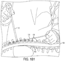
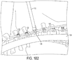
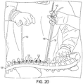
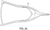
- FIG. 10 exemplary embodiments of the method and related tools in accordance with the disclosed subject matter are shown in Figs. 1-9 as applied to a spine model (e.g. a sawbone).
- a spine model e.g. a sawbone
- the described method can be used with a variety of techniques and indications, including minimally invasive techniques.
- reference to the location of the target sites and to the specific brand or make of instruments and implants is for purpose of illustration only, and not limitation.
- an exemplary technique which does not form part of the present invention for spinal correction surgery 200 is provided.
- the patient is placed on the operating table in the lateral decubitus position with the right side up and is appropriately secured.
- the patient undergoes the standard preparation and drape.
- two small (for example, 5-mm) thoracoscopic portals are placed in the anterior axillary line around T6 and T8.
- An additional 5-mm portal can be placed around T10 if additional retraction is needed.
- a thoracoscopic camera is inserted through one of the portals and CO2 insufflation utilized.
- a scalpel such as a Harmonic scalpel, is inserted through another portal, and levels are confirmed with fluoroscopy.
- the pleura is dissected off the anterolateral aspect of the vertebral body and reflected to visualize the rib head.
- the segmental vessels are sacrificed at every level using the Harmonic scalpel, with ligature staples used if necessary. Additionally or alternatively, smaller or modified staples can be used without sacrificing the segmental vessels. Care is taken to ensure that the disc space is not violated.
- a 3-cm incision can be made in the posterior axillary line around the T6/7 interspace.
- the location of this incision can be determined by first injecting saline through a syringe/needle to ensure optimal access/angulation for screw placement.
- the muscles can be dissected using the Bovie bipolar electrocautery device and undermined to provide maximal access.
- a 15-mm portal is inserted and, under direct visualization, a vertebral body staple is placed just anterior to the rib head.
- the positioning of the staple is confirmed with an AP fluoroscopy image. Once optimized, the staple is malleted into place.
- the technique can be performed without placing a vertebral body staple, and the anchor devices 120, embodied herein as vertebral body screws, can be placed as described herein below.
- a tap is introduced into the staple hole and directed toward the contralateral pedicle on the AP fluoroscopy image.
- the sagittal orientation is confirmed by making a second working incision around the T9/10 interspace, introducing a second 15-mm portal, and placing the camera through that portal to more accurately assess the sagittal angulation.
- the target is the contralateral rib head. Care is taken not to breach the spinal canal.
- the technique can be performed without the tap, and the anchor devices 120, embodied herein as a vertebral body screw, can be inserted directly.
- the tap is progressively advanced until 1-2 threads are emerging out of the contralateral side of the vertebral body. At this point, the length of the anchor device 120 is determined.
- the tap is removed and any bony bleeding stopped with a hemostatic agent.
- the technique can be performed without bicortical purchase, for example by inserting the tap and/or the screw a shorter distance.
- the anchor device 120 is placed again under direct AP fluoroscopic guidance.
- the anchor device 120 can be chosen as an appropriate-size Zimmer Dynesys 6.0 millimeter screw, which can be advanced by hand. Bicortical purchase is confirmed. If a thoracotomy is performed, the screw on the contralateral side can be palpatated to confirm bicortical fixation.
- the steps of placement of the screw or similar anchor device 120 are repeated for each vertebral body segment 102 as required or desired.
- An inferior 3-cm thoracoscopic portal incision over the T9-T10 interspace in the posterior axillary line is made to assist in placing the bottom anchor devices 120. Additionally, a larger distal incision of 5 cm or greater and/or thoracotomy can be provided to better facilitate visualization and application of the corrective forces. 15-mm portals are placed into each-of the three incisions in the posterior axillary line. In addition, three 5-mm portals are placed through the portals in the anterior axillary line. It is understood that alternative access openings can be used as desired or appropriate.
- a tether 130 such as a PET web, is introduced from the inferior most 15-mm portal.
- the tether 130 can be introduced through any of the other portals.
- the tether 130 is grabbed with a thoracoscopic grasper which is introduced through a 5-mm anterior portal.
- the tether 130 is then placed within the channels of the anchor devices, e.g. the tulips of the anchor devices 120.
- a set screw or similar fastener 122 is introduced through the superior most 15-mm portal and tightened on the top most anchor device 120 to secure the first end of the tether 130 in the channel, in this instance T6, thereby securing the tether 130 to the anchor device 120.
- a thoracoscopic vertebral body pusher 110 is introduced through the middle 15-mm portal, and at 260, used to apply a downward and anterior translational force to the next adjacent vertebral body segment 102 for coronal and axial correction of the spine 100 across the apex, as shown for illustration in Figs. 1A-D .
- the thoracoscopic vertebral body pusher 110 for use herein is configured to be longer than a normal body pusher, in order to extend through a thoracoscopic portal and still reach the spine 100.
- a longer set screw inserter 112 which can fit inside the pusher 110, complements the longer pusher 110 to accommodate the longer instrument.
- a modified multilevel vertebral body pusher 110 can be provided to grasp tulips of up to 3 anchor devices 120 simultaneously, to allow for maximal curve correction via translation over up to 3 vertebral segments. This allows a translational corrective force to be applied to correct the spinal curvature.
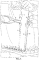
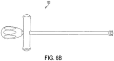
- a distractor 150 as shown in Fig. 5 can be used to facilitate this removal. Dislodging the set screw driver 112 using a distractor can minimize the risk of weakening the screw-bone interface. Similarly, if removing the modified pusher 110 from the anchor device 120 becomes difficult, using a popper tool 160 as shown in Figs. 6A-D can facilitate such removal.
- a pusher 110 is then introduced through the top most 15-mm portal and engaged with the second anchor device 120 from the top (for example, T7).
- a tensioner tower 140 is placed at an inferior anchor device 120, such as the next to last distal anchor device 120, so as not to stress the most distal fixation point in the construct (in this instance, T12).
- the tensioner 140 can be placed at a more proximal screw.
- a modified tensioner 142 is then applied to the tensioner tower 140, in order to apply tension to a second end of the tether 130.
- the tensioner 142 can include a self-locking feature.
- the tensioner 142 can be modified to include a locking cylinder through which the tether 130 can be fed and locked by pressing a button to engage a lock, such as a latching or abutting engagement.
- the tensioner 142 (such as depicted in Figs. 2A-B ) is maximally engaged on T11 to apply compressive forces across the convexity of the scoliotic curve in order to obtain 3-dimensional curve correction, as shown in Figs. 2C-F .
- the corresponding fastener 122 e.g. a set screw
- the corresponding fastener 122 is tightened to secure the tether 130 within the channel of the selected anchor device 120 with the corresponding vertebral body in position.
- two pushers 110 can be used for translation in addition to the distal tensioning, such as shown in Fig. 2F .
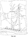
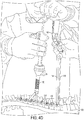
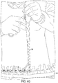
- distraction and/or compression forces can be applied between two anchor devices 120 to force shortening of the corresponding vertebral segments 102, as shown in Fig. 3A-D . If significant wedging between two vertebral segments 102 occurs, local distraction or compression forces can be applied as needed to correct the segmental deformity. The use of compression and/or distraction can help achieve maximal correction. In some patients, the bottom few vertebral bodies 102 can be distracted out to reduce or prevent overcorrection.
- a modified thoracoscopic compressor 180 can be used to apply a compressive force between two adjacent anchor devices 120 to adjust the relative position between the corresponding vertebral body segments 102, as shown in an exemplary embodiment in Figs. 4A-G .
- a modified thoracoscopic distractor can be used to apply a distractive force between two adjacent anchor devices 120 to adjust the relative position between the corresponding vertebral body segments 102.
- the modified thoracoscopic compressor 180 as shown in Figs. 4A-G has the advantage of applying compressive forces between two vertebral body segments 102 through a 15 mm thoracoscopic portal. Additionally, the modified thoracoscopic distractor 180 has the advantage of applying distractive forces between two vertebral segments 102 through a 15 mm thoracoscopic portal. In some embodiments, distraction and/or compression between vertebral body segments 102 and tightening of the fasteners 122 can be performed with a modified thoracoscopic 182 distractor, further modified to include a screwdriver 184 integrally formed therewith, as shown for example in Fig. 4H .
- the corrective processes of translation and tensioning, as well as compression and distraction as appropriate, are progressively repeated sequentially along each of the plurality of vertebral body segments 102 as needed (e.g. T7 to T11) until all of the fasteners 122 are tightened (e.g., from T6 to T11) to secure the tether 130 in their respective channels.
- the correction maneuvers are performed with fluoroscopic guidance and confirmation at each level.
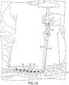
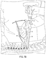
- the tensioner 142 is then removed from T11 and engaged with the bottom-most anchor device 120 (e.g. T12), and the tether 130 is appropriately tensioned between T11 and T12, as shown in an exemplary embodiment in Figs. 7A-C .
- a segment e.g. T11-T12
- the open compressor 175 as such as shown in Figs. 3D1 and 3D2
- the modified thoracoscopic compressor 180 such as shown in Fig. 4E
- a vertebral body segment 102 e.g. T11-T12
- distraction can be applied, either by the open distractor 170 (such as shown in Figs. 7B-C ) or by the modified thoracoscopic distractor 180 (such as shown in Fig. 5 ), to achieve correction.
- the excess tether 130 at either end can cut utilizing an 11 blade knife, such as a Harmonic scalpel, introduced through the inferior portal and the excess pieces removed.
- an 11 blade knife such as a Harmonic scalpel
- slack can be remain in the tether 130 between fasteners 122 in the lower vertebral body segments 102. In this manner, the tension in the tether 130 will not become excessive and cause overcorrection.
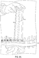
- Figs. 9A-B Leaving extra length and or leaving slack in the tether 130 between two anchor devices 120 can allow for growth of the patient and the ability for the system to self-adjust, or to enable a subsequent surgical intervention without the need to repeat all of the surgery steps.
- the access opening(s) in the patient can be closed in a conventional manner.
- the pleura can then be closed using a 2-0 prolene, and a chest tube is passed through the inferior most 5-mm portal site in the anterior axillary line.
- the wounds are closed in standard manner utilizing 0-prolene, 2-0 prolene, and 3-0 monocryl.
- exemplary 2-year results of patients receiving treatment according to the techniques, which do not form part of the present invention, of the disclosed subject matter are provided.
- Thoracic axial rotation as measured by a scoliometer went from 12.4 ⁇ 3.3° preoperatively to 6.9 ⁇ 3.4° at the most recent measurement (p ⁇ 0.01). Two patients returned to the operating room at 2 years postoperatively for loosening of the tether to prevent overcorrection.
- the patients were placed in the lateral decubitus position with the curve side up (for example and as embodied here, right-side up).
- the first five patients underwent a mini thoracotomy at T9-10 to allow improved 3-D assessment of the anatomy and confirm safe bicortical screw placement.
- the procedure has been performed thoracoscopically.
- Three 5-mm working thoracoscopic ports were placed in a triangular configuration with the apex at the fifth intercostal space (ICS) in the anterior axillary line and the base formed from two ports in the mid-axillary line, one in ICS 3 and the other in ICS 8.
- ICS intercostal space
- a camera was inserted into one port, a harmonic scalpel in another, and an endoscopic "peanut" in the third port to begin the dissection.
- the parietal pleura was incised along the lateral aspect of the vertebral bodies anterior to the rib heads in sequential fashion along the length of the curve. Proper position and vertebral levels were checked and confirmed using C-arm fluoroscopy in anteroposterior (AP) and lateral positions.
- AP teroposterior
- the pleura was incised for the length of spine to be tethered and reflected off the anterolateral aspect of the vertebral bodies on the convex side of the curve.
- the segmental vessels were identified, coagulated, and divided. Care was taken to reduce or prevent the disk spaces from being touched.
- a 15-mm working port was placed in the posterior axillary line to facilitate safe placement of vertebral body screws (embodied herein using 3 screws per incision).
- a 3-prong staple was placed on the anterior aspect of the vertebral body adjacent to the rib head. The position of the staple was confirmed using C-arm fluoroscopy in AP and lateral views. The staple was confirmed to be located anterior to the rib head, and positioning the staple proximate the foramen was avoided.
- the screw hole was tapped under fluoroscopic guidance aiming for the contralateral rib head.
- a suitable screw length was selected, and the screw was placed. Proper position was again checked and confirmed using C-arm fluoroscopy. The remaining screws were placed in a similar manner.
- the tether was passed distal to proximal through the most caudal 15 mm port utilizing the working ports and placed into the screw heads.
- a tensioning device was placed on a caudal level screw and tensioned to remove any loose tether. Subsequently, utilizing a combination of apical translation, compression, and tensioning of the tether, the curvature of the spine was corrected as discussed herein, and the set screws were tightened to hold this correction. Fluoroscopy was utilized after each screw was engaged and tightened into the tether to confirm continued correction of the curvature.
- the tether was trimmed leaving approximately 2 cm of length on either side to accommodate potential future lengthening.
- a chest tube was placed through one of the 5-mm port sites, the hemithorax was irrigated, the lung reinflated under direct vision, and the incisions were closed in layers.
- the average preoperative thoracic kyphosis was 20.8 ⁇ 13.3°.
- Average preoperative thoracic kyphosis decreased to 13.5 ⁇ 8.7° on first erect and then gradually increased to 17.9 ⁇ 7.0° at one year and 21.6 ⁇ 12.7° at 2-year follow-up.
- the average preoperative lumbar lordosis was 47.5 + 10.6° and remained stable (54.9 + 13.1°) at 2 years. As such, no statistically significant change occurred in the sagittal measurements. Table 4.
- results illustrate a gradual improvement of spine deformity with a low risk profile using the techniques of the disclosed subject matter.
- a twelve-year-and-five-month-old female presented with a right-sided, 34° main thoracic curve from T6-T12 and a lumbar curve of 34° from T12-L4.
- the patient's thoracic kyphosis was 22° (T5-T12).
- the patient had a Risser score of 0, and a Sanders score of 3.
- flexibility of the thoracic curve measured 12° and the lumbar curve measured 2.3°.
- the patient was anesthetized and positioned in the lateral decubitus position with the right side up.
- Two small working thoracoscopic portals were made in the anterior axillary line.
- a 15-mm working portal and a small thoracotomy incision were also made on the mid axillary line.
- the anterior spine was prepared with stripping the pleura circumferentially around the spine and transection of the segmental vessels at the vertebral levels that would be instrumented.
- a 3-prong staple was impacted into place on the anterior aspect of the vertebral bodies just anterior to the rib head under C-arm guidance. Screw holes were drilled and tapped and screw length estimated.
- Dynesys screws were placed along the length of the construct from T6 to T12.
- a flexible PET tether (Zimmer Dynesys, Raytham, MA) was placed through the thoracotomy site into the screw head of the superior most screw, which was secured with a set screw. The tether was sequentially placed into all of the additional screw heads. Tension was placed on the tether through a custom tensioning device placed on T11 (one level proximal from the end instrumented vertebra so as to not cause screw loosening). Careful reduction translation force was placed onto the spine at the apical screw simultaneously as the tether was tensioned and the set screw tightened at T7.
- the surgery progressed in a similar fashion distally with the tether sequentially tensioned and then attached to each screw via a set screw progressing proximally to distally to T12.
- the tether was trimmed leaving 2.5 cm extra tether beyond the proximal and distal screw for future adjustment (e.g., lengthening) if needed.
- the wound was closed, a chest tube inserted, and the patient was turned to a right lateral decubitus position.
- Anterior stapling of the lumbar curve was performed from T12 to L3.
- Stapling of L3-4 was avoided, at least in part because it can be unnecessary for curve control and can involve significant retraction on the psoas muscle.
- Global imaging of the spine in both AP and lateral views was performed, and visual confirmation of significant reduction of the curvature in the coronal plane and appropriate alignment in the sagittal plane was obtained.
- the thoracic main curve measured 11° intraoperatively while the patient was in the supine position in the operating room. Prior to discharge the patients curve measured 15° on the first erect x-ray. Following up x-rays were obtained at 6 weeks, 3 months, 6 months, 12 months, 18 months and 2 years. With reference to Table 6, the patient's films showed progressive correction of the coronal deformity over the course of the follow up period.
- the thoracic curve measured 13° at the 6-week follow up, 10° at 3 months, 6° at six months.
- the patient's main thoracic curve measured 0 °, representing a 100% correction. However, between 12 and 18 months, the patient's main thoracic curve began to overcorrect. At 18 months her main thoracic curve measured -14°. At this time, the patient was still thought to have some residual growth remaining. As such, at 21 months after her index surgery, the decision was made to adjust the tether.
- the most distal 3 levels of the tether were loosened and distraction techniques were applied to the spine.
- the tether was trimmed leaving 2.5 cm extra tether beyond the distal screw, which allowed for the adjustment.
- intraoperative films were taken. The patient's main curve measured 0° intraoperatively and 1° at first erect. At the 24-month, follow-up, the curve measured -2.7°.
- the patient's preoperative proximal and lumbar curves measured 5.7° (T1-T4) and 34° (T10-L4), respectively.
- the proximal curve measured 12° and the lumbar curve measured 16°.
- the proximal curve measured 0° and the lumbar curve measured 6.3°.
- the patient's preoperative thoracic kyphosis measured 32° (T4-T12), and her lumbar lordosis measured 34° (L1-L5).
- kyphosis was measured at 16° and lordosis at 20°.
- the patient's thoracic kyphosis measured 17° and her lumbar lordosis measured 31°.
Landscapes
- Health & Medical Sciences (AREA)
- Orthopedic Medicine & Surgery (AREA)
- Neurology (AREA)
- Life Sciences & Earth Sciences (AREA)
- Surgery (AREA)
- Heart & Thoracic Surgery (AREA)
- Engineering & Computer Science (AREA)
- Biomedical Technology (AREA)
- Nuclear Medicine, Radiotherapy & Molecular Imaging (AREA)
- Medical Informatics (AREA)
- Molecular Biology (AREA)
- Animal Behavior & Ethology (AREA)
- General Health & Medical Sciences (AREA)
- Public Health (AREA)
- Veterinary Medicine (AREA)
- Prostheses (AREA)
- Surgical Instruments (AREA)
Claims (14)
- Kit zur Durchführung einer Wirbelsäulenkorrektur, das aus Folgendem besteht:einer Vielzahl von Verankerungsvorrichtungen (120), die dazu ausgestaltet sind, auf eine Vielzahl von Wirbelkörpern (102) vor dem Rippenkopf implantiert zu werden, wobei jede Verankerungsvorrichtung (120) einen darin definierten Kanal hat,einer Anbindung (130), die dazu ausgestaltet ist, in den Kanal jeder der Verankerungsvorrichtungen (120) angeordnet zu werden,einem Schieberwerkzeug (110), das dazu ausgestaltet ist, eine ausgewählte Verankerungsvorrichtung (120) in Eingriff zu nehmen, um den der ausgewählten Verankerungsvorrichtung (120) entsprechenden Wirbelkörper (102) zu translatieren,einer Kompressionsvorrichtung (175, 180), die dazu ausgestaltet ist, eine Kompressionskraft zwischen zwei benachbarten Verankerungsvorrichtungen (120) auszuüben, undeine Spannvorrichtung (142), die dazu ausgestaltet ist, eine Spannung auf die Anbingung (130) auszuüben.
- Kit nach Anspruch 1, wobei die Vielzahl von Verankerungsvorrichtungen (120) eine Vielzahl von Wirbelsäulenschrauben umfasst.
- Kit nach Anspruch 2, wobei jede Wirbelsäulenschraube einen Gewindeschaftabschnitt und einen Kopfabschnitt aufweist, wobei der Kanal jeder Wirbelsäulenschraube in der Nähe des Kopfabschnitts angeordnet ist.
- Kit nach Anspruch 2, wobei jede Wirbelsäulenschraube eine Befestigungsvorrichtung (122) aufweist, um die Anbindung (130) in dem Kanal davon zu befestigen.
- Kit nach Anspruch 1, wobei die Anbindung (130) aus Polyethylenterephthalat (PET) hergestellt ist.
- Kit nach Anspruch 1, ferner umfassend mindestens ein Thorakoskopieportal.
- Kit nach Anspruch 6, wobei der Schieber ein thorakoskopischer Wirbelkörperschieber (110) ist, der dazu ausgestaltet ist, in dem Thorakoskopieportal aufgenommen zu werden.
- Kit nach Anspruch 7, wobei der Schieber (110) dazu ausgestaltet ist, eine darin eingeführte Stellschraube (122) aufzunehmen.
- Kit nach Anspruch 6, wobei die Kompressionsvorrichtung (175, 180) eine thorakoskopische Kompressionsvorrichtung (180) ist, die dazu ausgestaltet ist, in dem Thorakoskopieportal aufgenommen zu werden.
- Kit nach Anspruch 9, wobei die Kompressionsvorrichtung (180) einen integral damit ausgebildeten Schraubendreher (184) hat.
- Kit nach Anspruch 1, ferner umfassend eine Distraktionsvorrichtung (170, 180), die dazu ausgestaltet ist, eine Distraktionskraft zwischen zwei benachbarten Verankerungsvorrichtungen (120) auszuüben.
- Kit nach Anspruch 11, wobei die Distraktionsvorrichtung eine thorakoskopische Distraktionsvorrichtung (180) ist, die dazu ausgestaltet ist, in einem Thorakoskopieportal aufgenommen zu werden.
- Kit nach Anspruch 1, wobei die Spannvorrichtung (142) einen Spannturm umfasst.
- Kit nach Anspruch 1, wobei die Spannvorrichtung (142) ein Selbstverriegelungsmerkmal umfasst, um die Anbindung (130) zu verriegeln.
Applications Claiming Priority (2)
| Application Number | Priority Date | Filing Date | Title |
|---|---|---|---|
| US201361791982P | 2013-03-15 | 2013-03-15 | |
| PCT/US2014/028016 WO2014143862A1 (en) | 2013-03-15 | 2014-03-14 | Methods and techniques for spinal surgery |
Publications (3)
| Publication Number | Publication Date |
|---|---|
| EP2967653A1 EP2967653A1 (de) | 2016-01-20 |
| EP2967653A4 EP2967653A4 (de) | 2016-11-23 |
| EP2967653B1 true EP2967653B1 (de) | 2019-05-29 |
Family
ID=51537547
Family Applications (1)
| Application Number | Title | Priority Date | Filing Date |
|---|---|---|---|
| EP14763561.9A Active EP2967653B1 (de) | 2013-03-15 | 2014-03-14 | Techniken für die wirbelsäulenchirurgie |
Country Status (4)
| Country | Link |
|---|---|
| US (2) | US10278736B2 (de) |
| EP (1) | EP2967653B1 (de) |
| ES (1) | ES2745673T3 (de) |
| WO (1) | WO2014143862A1 (de) |
Cited By (1)
| Publication number | Priority date | Publication date | Assignee | Title |
|---|---|---|---|---|
| USRE49586E1 (en) | 2013-03-15 | 2023-07-25 | Shriners Hospitals For Children | Methods and techniques for spinal surgery |
Families Citing this family (11)
| Publication number | Priority date | Publication date | Assignee | Title |
|---|---|---|---|---|
| US10194960B1 (en) * | 2015-12-03 | 2019-02-05 | Nuvasive, Inc. | Spinal compression instrument and related methods |
| US10667845B2 (en) | 2017-07-19 | 2020-06-02 | Mayo Foundation For Medical Education And Research | Vertebral tethering |
| CA3153819A1 (en) | 2017-08-29 | 2019-03-07 | Zimmer Biomet Spine, Inc. | Surgical cord tensioning devices, systems, and methods |
| US10939941B2 (en) | 2017-08-29 | 2021-03-09 | Zimmer Biomet Spine, Inc. | Surgical cord tensioning devices, systems, and methods |
| US11020149B2 (en) * | 2018-02-28 | 2021-06-01 | Globus Medical Inc. | Scoliosis correction systems, methods, and instruments |
| US11759239B2 (en) | 2018-09-24 | 2023-09-19 | Astura Medical Inc | MIS multi-level compressor / distractor |
| US11712272B2 (en) | 2018-12-18 | 2023-08-01 | Frank J. Schwab | Technologies for lines coupled to spines |
| US11389204B2 (en) | 2020-12-17 | 2022-07-19 | Institute For Spine & Scoliosis, P.A. | Method for improved spinal correction surgery implementing non-fusion anterior scoliosis correction techniques for release of discs |
| US12193711B2 (en) * | 2020-12-17 | 2025-01-14 | Md Antonacci Family Trust | Method for improved spinal correction surgery implementing non-fusion anterior scoliosis correction techniques |
| US12310629B2 (en) | 2021-02-10 | 2025-05-27 | Alphatec Spine, Inc. | Methods and devices for augmenting the spine |
| US12343055B1 (en) | 2024-08-02 | 2025-07-01 | Institute For Spine & Scoliosis, P.A. | Anchor device for bone implantation during surgical procedures |
Family Cites Families (32)
| Publication number | Priority date | Publication date | Assignee | Title |
|---|---|---|---|---|
| PL105977B1 (pl) * | 1976-06-28 | 1979-11-30 | Wyzsza Szkola Inzynierska | Przyrzad do korekcji skrzywien kregoslupa |
| US5616143A (en) * | 1995-02-06 | 1997-04-01 | Schlapfer; Johannes F. | Surgical forceps |
| US6296643B1 (en) | 1999-04-23 | 2001-10-02 | Sdgi Holdings, Inc. | Device for the correction of spinal deformities through vertebral body tethering without fusion |
| US6299613B1 (en) | 1999-04-23 | 2001-10-09 | Sdgi Holdings, Inc. | Method for the correction of spinal deformities through vertebral body tethering without fusion |
| US7056321B2 (en) * | 2000-08-01 | 2006-06-06 | Endius, Incorporated | Method of securing vertebrae |
| US7189244B2 (en) * | 2002-08-02 | 2007-03-13 | Depuy Spine, Inc. | Compressor for use in minimally invasive surgery |
| EP3222231A1 (de) * | 2002-10-30 | 2017-09-27 | Zimmer Spine, Inc. | Spinaler stabilisierungssystemeinsatz und verfahren |
| DE50302889D1 (de) * | 2003-04-24 | 2006-05-18 | Zimmer Gmbh Winterthur | Instrumentensystem für Pedikelschrauben |
| JP2005169064A (ja) | 2003-05-22 | 2005-06-30 | Sohei Ebara | 脊柱変形矯正装置及びその使用方法 |
| US20050090899A1 (en) * | 2003-10-24 | 2005-04-28 | Dipoto Gene | Methods and apparatuses for treating the spine through an access device |
| US7527638B2 (en) * | 2003-12-16 | 2009-05-05 | Depuy Spine, Inc. | Methods and devices for minimally invasive spinal fixation element placement |
| US7666188B2 (en) * | 2003-12-16 | 2010-02-23 | Depuy Spine, Inc. | Methods and devices for spinal fixation element placement |
| US20050203511A1 (en) * | 2004-03-02 | 2005-09-15 | Wilson-Macdonald James | Orthopaedics device and system |
| GB2415703A (en) | 2004-07-02 | 2006-01-04 | Hewlett Packard Development Co | Liquid crystal display device |
| US7686814B2 (en) * | 2004-07-06 | 2010-03-30 | Warsaw Orthopedic, Inc. | Systems and methods for compressing and distracting vertebrae of the spinal column |
| US7465306B2 (en) * | 2004-08-13 | 2008-12-16 | Warsaw Orthopedic, Inc. | System and method for positioning a connecting member adjacent the spinal column in minimally invasive procedures |
| US8123749B2 (en) * | 2005-03-24 | 2012-02-28 | Depuy Spine, Inc. | Low profile spinal tethering systems |
| US7842072B2 (en) * | 2006-03-16 | 2010-11-30 | Zimmer Spine, Inc. | Spinal fixation device with variable stiffness |
| WO2007146833A2 (en) * | 2006-06-09 | 2007-12-21 | Endius, Inc. | Methods and apparatus for access to and/or treatment of the spine |
| US20080009863A1 (en) * | 2006-06-23 | 2008-01-10 | Zimmer Spine, Inc. | Pedicle screw distractor and associated method of use |
| US8052720B2 (en) * | 2006-11-09 | 2011-11-08 | Zimmer Spine, Inc. | Minimally invasive pedicle screw access system and associated method |
| US7824430B2 (en) * | 2006-12-08 | 2010-11-02 | Warsaw Orthopedic, Inc. | Methods and devices for treating a multi-level spinal deformity |
| US8454662B2 (en) * | 2006-12-08 | 2013-06-04 | Warsaw Orthopedic, Inc. | Tethers with strength limits for treating vertebral members |
| US20080249531A1 (en) * | 2007-02-27 | 2008-10-09 | Warsaw Orthopedic, Inc. | Instruments and methods for minimally invasive insertion of dynamic implants |
| US8323294B2 (en) * | 2007-08-21 | 2012-12-04 | Depuy Spine, Inc. | Tether tensioning instrument |
| US9277940B2 (en) * | 2008-02-05 | 2016-03-08 | Zimmer Spine, Inc. | System and method for insertion of flexible spinal stabilization element |
| US20090248077A1 (en) * | 2008-03-31 | 2009-10-01 | Derrick William Johns | Hybrid dynamic stabilization |
| FR2929830A1 (fr) * | 2008-04-15 | 2009-10-16 | Warsaw Orthopedic Inc | Outil chirurgical pour manipuler un implant, plus particulierement un element d'ancrage implante dans une vertebre |
| US8292930B2 (en) * | 2008-05-06 | 2012-10-23 | Warsaw Orthopedic, Inc. | Tethering devices and methods to treat a spinal deformity |
| US20100042149A1 (en) * | 2008-08-18 | 2010-02-18 | Chao Nam T | Pelvic obliquity correction instrument |
| US8617220B2 (en) | 2012-01-04 | 2013-12-31 | Warsaw Orthopedic, Inc. | System and method for correction of a spinal disorder |
| EP2967653B1 (de) | 2013-03-15 | 2019-05-29 | Shriners Hospitals for Children | Techniken für die wirbelsäulenchirurgie |
-
2014
- 2014-03-14 EP EP14763561.9A patent/EP2967653B1/de active Active
- 2014-03-14 ES ES14763561T patent/ES2745673T3/es active Active
- 2014-03-14 WO PCT/US2014/028016 patent/WO2014143862A1/en not_active Ceased
-
2015
- 2015-09-15 US US14/855,147 patent/US10278736B2/en not_active Ceased
-
2021
- 2021-05-07 US US17/314,891 patent/USRE49586E1/en active Active
Non-Patent Citations (1)
| Title |
|---|
| None * |
Cited By (1)
| Publication number | Priority date | Publication date | Assignee | Title |
|---|---|---|---|---|
| USRE49586E1 (en) | 2013-03-15 | 2023-07-25 | Shriners Hospitals For Children | Methods and techniques for spinal surgery |
Also Published As
| Publication number | Publication date |
|---|---|
| US10278736B2 (en) | 2019-05-07 |
| ES2745673T3 (es) | 2020-03-03 |
| US20160000468A1 (en) | 2016-01-07 |
| WO2014143862A1 (en) | 2014-09-18 |
| USRE49586E1 (en) | 2023-07-25 |
| EP2967653A4 (de) | 2016-11-23 |
| EP2967653A1 (de) | 2016-01-20 |
Similar Documents
| Publication | Publication Date | Title |
|---|---|---|
| USRE49586E1 (en) | Methods and techniques for spinal surgery | |
| US12185990B2 (en) | Spinal alignment frame | |
| US20240407812A1 (en) | Spinal trauma correction and fixation | |
| US11723697B2 (en) | Patient-mounted surgical support | |
| US11116551B2 (en) | Lamina implants and methods for spinal decompression | |
| JP5314025B2 (ja) | 整形外科インプラントシステム | |
| US8343200B2 (en) | Orthopedic screw system | |
| EP2187825B1 (de) | Wirbelsäulen-vernetzungsgerät für die minimal-invasive chirurgie | |
| US11389209B2 (en) | Surgical plating systems, devices, and related methods | |
| US9050147B2 (en) | System and methods for minimally invasive spine surgery | |
| US11109894B2 (en) | Apparatus, system, and method for spinal vertebrae stabilization | |
| US20230032049A1 (en) | Systems and methods for treatment of spinal deformities | |
| US20250275791A1 (en) | Pedicle based retractor with screw gate | |
| US12484936B1 (en) | Systems and methods for treating spinal conditions | |
| Kisinde et al. | Posterior Cervical Instrumentation | |
| D’Andrea et al. | Intervertebral stapling for spinal deformity | |
| Betz et al. | Pediatric deformity treatment update, including 3D correction concepts |
Legal Events
| Date | Code | Title | Description |
|---|---|---|---|
| PUAI | Public reference made under article 153(3) epc to a published international application that has entered the european phase |
Free format text: ORIGINAL CODE: 0009012 |
|
| 17P | Request for examination filed |
Effective date: 20150915 |
|
| AK | Designated contracting states |
Kind code of ref document: A1 Designated state(s): AL AT BE BG CH CY CZ DE DK EE ES FI FR GB GR HR HU IE IS IT LI LT LU LV MC MK MT NL NO PL PT RO RS SE SI SK SM TR |
|
| AX | Request for extension of the european patent |
Extension state: BA ME |
|
| DAX | Request for extension of the european patent (deleted) | ||
| A4 | Supplementary search report drawn up and despatched |
Effective date: 20161026 |
|
| RIC1 | Information provided on ipc code assigned before grant |
Ipc: A61B 17/88 20060101ALI20161020BHEP Ipc: A61B 17/58 20060101ALI20161020BHEP Ipc: A61B 17/56 20060101AFI20161020BHEP |
|
| REG | Reference to a national code |
Ref country code: DE Ref legal event code: R079 Ref document number: 602014047578 Country of ref document: DE Free format text: PREVIOUS MAIN CLASS: A61B0017560000 Ipc: A61B0017700000 |
|
| GRAP | Despatch of communication of intention to grant a patent |
Free format text: ORIGINAL CODE: EPIDOSNIGR1 |
|
| STAA | Information on the status of an ep patent application or granted ep patent |
Free format text: STATUS: GRANT OF PATENT IS INTENDED |
|
| RIC1 | Information provided on ipc code assigned before grant |
Ipc: A61B 17/70 20060101AFI20181128BHEP |
|
| INTG | Intention to grant announced |
Effective date: 20181219 |
|
| GRAS | Grant fee paid |
Free format text: ORIGINAL CODE: EPIDOSNIGR3 |
|
| GRAA | (expected) grant |
Free format text: ORIGINAL CODE: 0009210 |
|
| STAA | Information on the status of an ep patent application or granted ep patent |
Free format text: STATUS: THE PATENT HAS BEEN GRANTED |
|
| AK | Designated contracting states |
Kind code of ref document: B1 Designated state(s): AL AT BE BG CH CY CZ DE DK EE ES FI FR GB GR HR HU IE IS IT LI LT LU LV MC MK MT NL NO PL PT RO RS SE SI SK SM TR |
|
| REG | Reference to a national code |
Ref country code: GB Ref legal event code: FG4D |
|
| REG | Reference to a national code |
Ref country code: CH Ref legal event code: EP |
|
| REG | Reference to a national code |
Ref country code: AT Ref legal event code: REF Ref document number: 1137796 Country of ref document: AT Kind code of ref document: T Effective date: 20190615 |
|
| REG | Reference to a national code |
Ref country code: DE Ref legal event code: R096 Ref document number: 602014047578 Country of ref document: DE |
|
| REG | Reference to a national code |
Ref country code: IE Ref legal event code: FG4D |
|
| REG | Reference to a national code |
Ref country code: CH Ref legal event code: NV Representative=s name: VALIPAT S.A. C/O BOVARD SA NEUCHATEL, CH |
|
| REG | Reference to a national code |
Ref country code: NL Ref legal event code: MP Effective date: 20190529 |
|
| REG | Reference to a national code |
Ref country code: LT Ref legal event code: MG4D |
|
| PG25 | Lapsed in a contracting state [announced via postgrant information from national office to epo] |
Ref country code: AL Free format text: LAPSE BECAUSE OF FAILURE TO SUBMIT A TRANSLATION OF THE DESCRIPTION OR TO PAY THE FEE WITHIN THE PRESCRIBED TIME-LIMIT Effective date: 20190529 Ref country code: SE Free format text: LAPSE BECAUSE OF FAILURE TO SUBMIT A TRANSLATION OF THE DESCRIPTION OR TO PAY THE FEE WITHIN THE PRESCRIBED TIME-LIMIT Effective date: 20190529 Ref country code: FI Free format text: LAPSE BECAUSE OF FAILURE TO SUBMIT A TRANSLATION OF THE DESCRIPTION OR TO PAY THE FEE WITHIN THE PRESCRIBED TIME-LIMIT Effective date: 20190529 Ref country code: NO Free format text: LAPSE BECAUSE OF FAILURE TO SUBMIT A TRANSLATION OF THE DESCRIPTION OR TO PAY THE FEE WITHIN THE PRESCRIBED TIME-LIMIT Effective date: 20190829 Ref country code: HR Free format text: LAPSE BECAUSE OF FAILURE TO SUBMIT A TRANSLATION OF THE DESCRIPTION OR TO PAY THE FEE WITHIN THE PRESCRIBED TIME-LIMIT Effective date: 20190529 Ref country code: PT Free format text: LAPSE BECAUSE OF FAILURE TO SUBMIT A TRANSLATION OF THE DESCRIPTION OR TO PAY THE FEE WITHIN THE PRESCRIBED TIME-LIMIT Effective date: 20190930 Ref country code: LT Free format text: LAPSE BECAUSE OF FAILURE TO SUBMIT A TRANSLATION OF THE DESCRIPTION OR TO PAY THE FEE WITHIN THE PRESCRIBED TIME-LIMIT Effective date: 20190529 |
|
| PG25 | Lapsed in a contracting state [announced via postgrant information from national office to epo] |
Ref country code: RS Free format text: LAPSE BECAUSE OF FAILURE TO SUBMIT A TRANSLATION OF THE DESCRIPTION OR TO PAY THE FEE WITHIN THE PRESCRIBED TIME-LIMIT Effective date: 20190529 Ref country code: GR Free format text: LAPSE BECAUSE OF FAILURE TO SUBMIT A TRANSLATION OF THE DESCRIPTION OR TO PAY THE FEE WITHIN THE PRESCRIBED TIME-LIMIT Effective date: 20190830 Ref country code: BG Free format text: LAPSE BECAUSE OF FAILURE TO SUBMIT A TRANSLATION OF THE DESCRIPTION OR TO PAY THE FEE WITHIN THE PRESCRIBED TIME-LIMIT Effective date: 20190829 Ref country code: LV Free format text: LAPSE BECAUSE OF FAILURE TO SUBMIT A TRANSLATION OF THE DESCRIPTION OR TO PAY THE FEE WITHIN THE PRESCRIBED TIME-LIMIT Effective date: 20190529 |
|
| REG | Reference to a national code |
Ref country code: AT Ref legal event code: MK05 Ref document number: 1137796 Country of ref document: AT Kind code of ref document: T Effective date: 20190529 |
|
| PG25 | Lapsed in a contracting state [announced via postgrant information from national office to epo] |
Ref country code: NL Free format text: LAPSE BECAUSE OF FAILURE TO SUBMIT A TRANSLATION OF THE DESCRIPTION OR TO PAY THE FEE WITHIN THE PRESCRIBED TIME-LIMIT Effective date: 20190529 Ref country code: DK Free format text: LAPSE BECAUSE OF FAILURE TO SUBMIT A TRANSLATION OF THE DESCRIPTION OR TO PAY THE FEE WITHIN THE PRESCRIBED TIME-LIMIT Effective date: 20190529 Ref country code: EE Free format text: LAPSE BECAUSE OF FAILURE TO SUBMIT A TRANSLATION OF THE DESCRIPTION OR TO PAY THE FEE WITHIN THE PRESCRIBED TIME-LIMIT Effective date: 20190529 Ref country code: CZ Free format text: LAPSE BECAUSE OF FAILURE TO SUBMIT A TRANSLATION OF THE DESCRIPTION OR TO PAY THE FEE WITHIN THE PRESCRIBED TIME-LIMIT Effective date: 20190529 Ref country code: AT Free format text: LAPSE BECAUSE OF FAILURE TO SUBMIT A TRANSLATION OF THE DESCRIPTION OR TO PAY THE FEE WITHIN THE PRESCRIBED TIME-LIMIT Effective date: 20190529 Ref country code: SK Free format text: LAPSE BECAUSE OF FAILURE TO SUBMIT A TRANSLATION OF THE DESCRIPTION OR TO PAY THE FEE WITHIN THE PRESCRIBED TIME-LIMIT Effective date: 20190529 Ref country code: RO Free format text: LAPSE BECAUSE OF FAILURE TO SUBMIT A TRANSLATION OF THE DESCRIPTION OR TO PAY THE FEE WITHIN THE PRESCRIBED TIME-LIMIT Effective date: 20190529 |
|
| PG25 | Lapsed in a contracting state [announced via postgrant information from national office to epo] |
Ref country code: SM Free format text: LAPSE BECAUSE OF FAILURE TO SUBMIT A TRANSLATION OF THE DESCRIPTION OR TO PAY THE FEE WITHIN THE PRESCRIBED TIME-LIMIT Effective date: 20190529 |
|
| REG | Reference to a national code |
Ref country code: ES Ref legal event code: FG2A Ref document number: 2745673 Country of ref document: ES Kind code of ref document: T3 Effective date: 20200303 Ref country code: DE Ref legal event code: R097 Ref document number: 602014047578 Country of ref document: DE |
|
| PG25 | Lapsed in a contracting state [announced via postgrant information from national office to epo] |
Ref country code: TR Free format text: LAPSE BECAUSE OF FAILURE TO SUBMIT A TRANSLATION OF THE DESCRIPTION OR TO PAY THE FEE WITHIN THE PRESCRIBED TIME-LIMIT Effective date: 20190529 |
|
| PLBE | No opposition filed within time limit |
Free format text: ORIGINAL CODE: 0009261 |
|
| STAA | Information on the status of an ep patent application or granted ep patent |
Free format text: STATUS: NO OPPOSITION FILED WITHIN TIME LIMIT |
|
| PG25 | Lapsed in a contracting state [announced via postgrant information from national office to epo] |
Ref country code: PL Free format text: LAPSE BECAUSE OF FAILURE TO SUBMIT A TRANSLATION OF THE DESCRIPTION OR TO PAY THE FEE WITHIN THE PRESCRIBED TIME-LIMIT Effective date: 20190529 |
|
| 26N | No opposition filed |
Effective date: 20200303 |
|
| PG25 | Lapsed in a contracting state [announced via postgrant information from national office to epo] |
Ref country code: SI Free format text: LAPSE BECAUSE OF FAILURE TO SUBMIT A TRANSLATION OF THE DESCRIPTION OR TO PAY THE FEE WITHIN THE PRESCRIBED TIME-LIMIT Effective date: 20190529 |
|
| PG25 | Lapsed in a contracting state [announced via postgrant information from national office to epo] |
Ref country code: MC Free format text: LAPSE BECAUSE OF FAILURE TO SUBMIT A TRANSLATION OF THE DESCRIPTION OR TO PAY THE FEE WITHIN THE PRESCRIBED TIME-LIMIT Effective date: 20190529 |
|
| PGFP | Annual fee paid to national office [announced via postgrant information from national office to epo] |
Ref country code: LU Payment date: 20200911 Year of fee payment: 7 |
|
| REG | Reference to a national code |
Ref country code: BE Ref legal event code: MM Effective date: 20200331 |
|
| PG25 | Lapsed in a contracting state [announced via postgrant information from national office to epo] |
Ref country code: IE Free format text: LAPSE BECAUSE OF NON-PAYMENT OF DUE FEES Effective date: 20200314 |
|
| PG25 | Lapsed in a contracting state [announced via postgrant information from national office to epo] |
Ref country code: BE Free format text: LAPSE BECAUSE OF NON-PAYMENT OF DUE FEES Effective date: 20200331 |
|
| PG25 | Lapsed in a contracting state [announced via postgrant information from national office to epo] |
Ref country code: LU Free format text: LAPSE BECAUSE OF NON-PAYMENT OF DUE FEES Effective date: 20210314 |
|
| PG25 | Lapsed in a contracting state [announced via postgrant information from national office to epo] |
Ref country code: MT Free format text: LAPSE BECAUSE OF FAILURE TO SUBMIT A TRANSLATION OF THE DESCRIPTION OR TO PAY THE FEE WITHIN THE PRESCRIBED TIME-LIMIT Effective date: 20190529 Ref country code: CY Free format text: LAPSE BECAUSE OF FAILURE TO SUBMIT A TRANSLATION OF THE DESCRIPTION OR TO PAY THE FEE WITHIN THE PRESCRIBED TIME-LIMIT Effective date: 20190529 |
|
| PG25 | Lapsed in a contracting state [announced via postgrant information from national office to epo] |
Ref country code: MK Free format text: LAPSE BECAUSE OF FAILURE TO SUBMIT A TRANSLATION OF THE DESCRIPTION OR TO PAY THE FEE WITHIN THE PRESCRIBED TIME-LIMIT Effective date: 20190529 Ref country code: IS Free format text: LAPSE BECAUSE OF FAILURE TO SUBMIT A TRANSLATION OF THE DESCRIPTION OR TO PAY THE FEE WITHIN THE PRESCRIBED TIME-LIMIT Effective date: 20190929 |
|
| P01 | Opt-out of the competence of the unified patent court (upc) registered |
Effective date: 20230527 |
|
| PGFP | Annual fee paid to national office [announced via postgrant information from national office to epo] |
Ref country code: ES Payment date: 20250410 Year of fee payment: 12 |
|
| PGFP | Annual fee paid to national office [announced via postgrant information from national office to epo] |
Ref country code: CH Payment date: 20250401 Year of fee payment: 12 |
|
| PGFP | Annual fee paid to national office [announced via postgrant information from national office to epo] |
Ref country code: FR Payment date: 20251231 Year of fee payment: 13 |
|
| REG | Reference to a national code |
Ref country code: CH Ref legal event code: U11 Free format text: ST27 STATUS EVENT CODE: U-0-0-U10-U11 (AS PROVIDED BY THE NATIONAL OFFICE) Effective date: 20260401 |
|
| PGFP | Annual fee paid to national office [announced via postgrant information from national office to epo] |
Ref country code: GB Payment date: 20260106 Year of fee payment: 13 |
|
| PGFP | Annual fee paid to national office [announced via postgrant information from national office to epo] |
Ref country code: DE Payment date: 20260102 Year of fee payment: 13 |
|
| PGFP | Annual fee paid to national office [announced via postgrant information from national office to epo] |
Ref country code: IT Payment date: 20260220 Year of fee payment: 13 |