EP2967797B1 - Prothèse pour hernioplastie inguinale - Google Patents
Prothèse pour hernioplastie inguinale Download PDFInfo
- Publication number
- EP2967797B1 EP2967797B1 EP14722729.2A EP14722729A EP2967797B1 EP 2967797 B1 EP2967797 B1 EP 2967797B1 EP 14722729 A EP14722729 A EP 14722729A EP 2967797 B1 EP2967797 B1 EP 2967797B1
- Authority
- EP
- European Patent Office
- Prior art keywords
- prosthesis
- prosthesis according
- comprised
- longitudinal direction
- shape
- Prior art date
- Legal status (The legal status is an assumption and is not a legal conclusion. Google has not performed a legal analysis and makes no representation as to the accuracy of the status listed.)
- Active
Links
Images


Classifications
-
- A—HUMAN NECESSITIES
- A61—MEDICAL OR VETERINARY SCIENCE; HYGIENE
- A61F—FILTERS IMPLANTABLE INTO BLOOD VESSELS; PROSTHESES; DEVICES PROVIDING PATENCY TO, OR PREVENTING COLLAPSING OF, TUBULAR STRUCTURES OF THE BODY, e.g. STENTS; ORTHOPAEDIC, NURSING OR CONTRACEPTIVE DEVICES; FOMENTATION; TREATMENT OR PROTECTION OF EYES OR EARS; BANDAGES, DRESSINGS OR ABSORBENT PADS; FIRST-AID KITS
- A61F2/00—Filters implantable into blood vessels; Prostheses, i.e. artificial substitutes or replacements for parts of the body; Appliances for connecting them with the body; Devices providing patency to, or preventing collapsing of, tubular structures of the body, e.g. stents
- A61F2/0063—Implantable repair or support meshes, e.g. hernia meshes
-
- A—HUMAN NECESSITIES
- A61—MEDICAL OR VETERINARY SCIENCE; HYGIENE
- A61F—FILTERS IMPLANTABLE INTO BLOOD VESSELS; PROSTHESES; DEVICES PROVIDING PATENCY TO, OR PREVENTING COLLAPSING OF, TUBULAR STRUCTURES OF THE BODY, e.g. STENTS; ORTHOPAEDIC, NURSING OR CONTRACEPTIVE DEVICES; FOMENTATION; TREATMENT OR PROTECTION OF EYES OR EARS; BANDAGES, DRESSINGS OR ABSORBENT PADS; FIRST-AID KITS
- A61F2/00—Filters implantable into blood vessels; Prostheses, i.e. artificial substitutes or replacements for parts of the body; Appliances for connecting them with the body; Devices providing patency to, or preventing collapsing of, tubular structures of the body, e.g. stents
- A61F2/0063—Implantable repair or support meshes, e.g. hernia meshes
- A61F2002/0068—Implantable repair or support meshes, e.g. hernia meshes having a special mesh pattern
Definitions
- the present invention relates to a prosthesis for inguinal hernioplasty.
- hernia is a pathological leakage of an internal organ from the cavity that normally contains it through an aperture, an anatomic channel or more generally a discontinuity in the tissues. This disease requires a surgical operation of hernioplasty during which a prosthesis for parietal reinforcement is implanted in the area affected by the hernia.
- a tension free intervention method is known since 1974. This technique is based on the use of meshes having a high biocompatibility and ease of use in order to avoid anti-physiological tractions on the muscle aponeurotic structures in order to remarkably reduce the number of relapses compared to the techniques previously used.
- the method relies on the application of a possible prosthetic cap, better known as "plug", in the weak area of the floor of the inguinal canal, as well as of a mesh having a standardized size and shape that is placed below the fascia of the external oblique muscle.
- prostheses and surgical methods do not completely address the problems of post-operative pain, which in some cases continues in the form of chronic, neuralgic or somatic pain.
- known prostheses and techniques do not address serious pathological manifestations, albeit rare, due to the migration of plugs within the abdomen. In addition to this, a low risk of subsequent relapses is anyway present.
- a prosthesis according to the preamble of claim 1 is known from the document US-A-2005/0165425 .
- the aim of the present invention is therefore to provide a prosthesis for inguinal hernioplasty free from these drawbacks and particularly allowing to simplify hernioplasty methods while reducing post-surgery disturbs and risk of relapses. Said object is achieved with a prosthesis for inguinal hernioplasty whose main features are specified in the first claim, while other features are specified in the remaining claims.
- the prosthesis for inguinal hernioplasty allows to strengthen, directly and without traction, the whole weak area of the floor of the inguinal canal acting on the structure comprising the transverse fascia of the inguinal hiatus.
- the prompt fibroblastic response stimulated by the prosthesis generates together with the transverse fascia a new wall that at the same time reinforces the side, central and medial dimples wherein a hernia occurs.
- the prosthesis according to the present invention thus allows a simultaneous direct reinforcement of all the weak areas of the inguinal canal, thus avoiding recurrence of hernia and relapses.
- the particular shape of the prosthesis according to the present invention ensures its application in a mirror fashion and may thus be used for a right or left inguinal hernioplasty.
- Another advantage provided by the prosthesis for inguinal hernioplasty according to the present invention is the ability to perform a simple, fast, less traumatic and painless surgical intervention leading to an earlier discharge of the patient and allowing him to quickly return to his normal daily activities.
- the risk of prosthesis corrugation after its placement in the inguinal canal is reduced, and consequently the risk of somatic pain or troublesome sensations due to the presence of a foreign body, which occur when prior art prostheses are employed.
- the prosthesis according to the present invention remains anchored between the internal inguinal ring and the pubic tubercle.
- a further advantage of the prosthesis for inguinal hernioplasty according to the present invention is that the risk of chronic neuralgic pain is avoided, these pain occurring when prior art prosthesis are used due to the interference of the prosthesis with neural structures. The risk of migration of the prosthesis in the abdomen is also avoided.
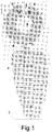
- the prosthesis for inguinal hernioplasty is made up of a surgical mesh and has an elongated shape extending from a first end 6 of the prosthesis to a second end 7 of the prosthesis along a longitudinal direction A.
- the prosthesis comprises a first portion 1 which includes said first end 6, a second portion 2 which includes said second end 7 and a third connecting portion 3 arranged between said first and second portions 1, 2.
- Said first portion 1 has a substantially ring or loop shape with a central hole 4.
- the first loop shaped portion is open or may be opened.
- open loop shape indicates a shape corresponding to a portion of a circular crown.
- open loop shape that may be opened indicates a loop shape that may be opened by the end user with a simple cut, for example a cut with scissors performed by the surgeon during a surgical intervention.
- longitudinal direction of said second portion 2 indicates a direction along which said prosthesis is mainly extended.
- longitudinal direction of the prosthesis is indicated for clarity's sake by a dashed line A.
- Said first portion 1 is adapted to be arranged around the spermatic cord of the patient, possibly after the prosthetic ring has been opened by cutting.
- the central hole 4 of the first portion 1 is suitable to accommodate the spermatic cord.
- said first portion 1 is closed around said cord by overlapping and joining free ends 1a and 1b of the said open loop in order to form a cone that is fitted into the internal inguinal orifice.
- the two free ends 1a and 1b can be appropriately cut so as to reduce the diameter of the hole 4 once prosthesis shaped like a cone has been closed.
- Said second end 7 of said second portion 2 is adapted to be arranged onto the pubic tubercle of the patient.
- Said second portion 2 has a substantially elongated shape in said longitudinal direction A of the prosthesis, i.e. the second portion 2 has a length in said longitudinal direction A of the prosthesis that is greater than its width in a direction transverse to said longitudinal direction A.
- width is to be construed as the size of the parts concerned in a transverse direction, for example perpendicular to said longitudinal direction A, and must not to be confused with the thickness of the prosthesis, which corresponds to the thickness the surgical mesh and is much lower than the other dimensions considered.
- said second portion 2 has a shape tapering towards said second end 7 of the prosthesis, i.e. its width at said end 7 is lower than the width at the end joined to the connecting portion 3.
- said connecting portion 3 is a reduced portion of the prosthesis having a width, i.e. a size transverse to said longitudinal direction A, which is lower than the width of said first portion 1 as well as lower than the width of said second portion 2.
- the prosthesis according to the present invention integrates a prosthetic plug with a reinforcement part of the transverse fascia and may be applied and anchored between the side dimple and the pubic tubercle, avoiding the risk of migration of the plug and of corrugations of the reinforcement part either during the application step or during the permanence of the prosthesis in the inguinal canal of the patient.
- the connecting portion 3 preferably has a width transverse to said longitudinal direction A which is lower than one third of the maximum width of said second portion 2 in the transverse direction.
- the connecting portion 3 has a width transverse to said longitudinal direction A which is lower than the diameter of the central hole 4.
- the connecting portion 3 preferably has a width lower than 1.0 cm, more preferably lower than 0.8 cm.
- the shape of the prosthesis is asymmetric.
- said first portion 1 is offset relative to the second portion 2.
- the first portion 1 is displaced relative to the second portion 2 in a transverse direction T perpendicular to the longitudinal direction A.
- said first portion 1 has the shape of an open ring comprising an opening 5 connected to said central hole 4. Said opening 5 thus defines the two free ends 1a, 1b of said first portion 1.
- This opening 5 is preferably arranged at a certain distance from the connecting portion 3.
- the angular distance between said opening 5 and said connecting portion 3 relative to the central point is greater than 45°, preferably greater than 90°.
- said angular distance is comprised between 120° and 180°.
- said angular distance is about 180°, i.e. the opening 5 and said connecting portion 3 are substantially diametrically opposite to one another relative to the central point of the first portion 1.
- angular distance between said opening 5 and said connecting portion 3 with respect to the central point of the first portion, indicates the size of the angle between a first straight line connecting the central point of the first portion 1 with a point of said opening 5 and a second straight line connecting the central point with a point of said connecting portion 3.
- said second portion 2 has a convex shape, substantially inscribed in a trapezoid, and comprises at least one substantially straight side adjacent to said connecting portion and two curved sides.
- said second portion 2 has two substantially straight sides opposite to one another and two curved sides.
- the two substantially straight sides are preferably substantially parallel to each other and one of them, namely the one adjacent to the connecting portion 3, has a length greater than the length of the side that is located at the distal end 7 of the prosthesis. Furthermore, one of the two curved sides preferably has an average curvature radius greater than the other curved side.
- the two substantially straight sides are preferably substantially orthogonal to said longitudinal direction of the prosthesis.
- said connecting portion 3 is joined to the second portion 2 approximately in the middle of the substantially straight larger side and said connecting portion 3 has substantially the shape of a parallelogram.
- connection areas between said connecting portion 3 and said portions 1 and 2 have sharp corners, but according to an embodiment of the invention these angles may advantageously be rounded in order to provide the prosthesis with higher tensile and tear strengths.
- said connecting portion 3 has substantially the shape of a rhombus, preferably having a side dimension lower than or equal to 1 cm, more preferably lower than 0.8 cm.
- said parallelogram or rhombus has two opposed internal angles whose size is comprised between 60° and 80°, more preferably between 65° and 70°. This allows to obtain the offset arrangement of the first portion 1 with respect to the second portion 2 when considering the longitudinal direction A of the prosthesis.
- the connecting portion 3 is joined to the second portion 2 approximately in the middle of said substantially straight larger side.
- the ring forming the first portion preferably has a diameter comprised between 3.0 and 6.0 cm, more preferably such a diameter is comprised between 3.3 cm and 3.7 cm.
- the central hole preferably has a diameter comprised between 1.0 and 2.0 cm, more preferably comprised between 1.3 cm and 1.7 cm.
- one of the substantially straight sides has a length comprised between 2.0 cm and 3.5 cm, more preferably comprised between 2.0 cm and 3.1 cm.
- the other substantially straight side instead has a length comprised between 0.5 and 1.5 cm, more preferably comprised between 0.7 cm and 1.3 cm.
- the greater width of the second portion 2 in a direction transverse to said longitudinal direction A, i.e. in a direction parallel to said substantially straight larger side, is preferably greater than the size of the substantially straight larger side.
- said greater width of the second portion 2 is comprised between 2.0 cm and 4.0 cm, more preferably comprised between 2.3 cm and 3.3 cm.
- This greater width of the second portion 2 is preferably positioned in the part of the portion 2 that is closer to said first portion 1, more preferably within the upper half of the second portion 2 with respect to the longitudinal direction.
- the distance between said substantially straight side having a greater length and the other substantially straight side i.e. the length of the second portion 2 in the longitudinal direction A, is comprised between about 3.0 cm and 6.0 cm, more preferably comprised between 5.2 cm and 5.8 cm.
- said connecting portion 3 substantially has the shape of a rhombus having a side of about 0.5 cm.
- the first ring shaped portion has a diameter of about 3.5 cm, while said central hole has a diameter of about 1.5 cm.
- the substantially straight sides have lengths equal to 2.8 cm and 1.0 cm respectively and the distance between said substantially straight side having a greater length and the other substantially straight side is about 5.5 cm.
- the greater width of the second portion 2 is about 3 cm.
- the surgical prosthesis according to the present invention is formed by a mesh made of any material suitable for the manufacturing of prostheses for the abdominal wall.
- the prosthesis according to the present invention is preferably made of polypropylene.
- the prosthesis according to the present invention may be applied by way of a surgical method of simple implementation, which is less traumatic and painless compared to prior art methods. This method also allows early discharge of patients, who may quickly return to their normal daily activities, and is free from outcomes after surgery. Thanks to the arrangement of the prosthesis at a more specific target area, the risk of corrugations and interference with nerve structures is reduced.
- the surgical method comprises in a known way a step of cutting the superficial layers and of opening of the aponeurosis of the external oblique muscle.
- spermatic cord is carried out.
- the method of the invention there is no need to identify and isolate the neural structures under the aponeurosis of the external oblique muscle, i.e. the iliohypogastric nerve and the ilioinguinal nerve.
- a medial longitudinal cutting of the cremaster muscle and the of external spermatic fascia (fibrous cremaster sheath) is then performed a with diathermic coagulation device; these parts are then separated from the elements of the spermatic cord up to the inguinal ligament.
- the cremaster muscle which is the continuation of the internal abdominal oblique muscle, also is continuous to the pubic tubercle and the inguinal ligament and that it reaches the spermatic cord where it is arranged between the external and internal spermatic fasciae, eversion of the transverse fascia, also called common vaginal tunic.
- the hernial sac is identified and the elements of the spermatic cord are separated.
- hernial sac In the case of a direct or internal oblique hernia the hernial sac must be isolated from the surrounding structures, as well as from the transverse fascia up to the hernial neck, if any.
- the weak area is then flattened by way of plication of the transverse fascia.
- the internal inguinal ring intended to receive the first portion 1 of the prosthesis is then prepared.
- a prosthesis according to the present invention is applied to the rear wall as a reinforcement.
- the first portion 1 is cut and arranged so as to surround the elements of the spermatic cord by forming a prosthetic cone around them; such a cone is obtained by approaching the ends 1a and 1b of the first portion 1. These ends are appropriately cut, approached and arranged atop of each other in order to adapt the size of the prosthetic cone to the diameter of the spermatic cord. Once reached the correct size the prosthetic cone is closed around the spermatic cord by way of a suture point.
- the prosthetic cone is then fitted into the internal inguinal orifice, while the elements of the spermatic cord are preferably moved upwards, e.g. by way of a Bottini forceps, in order to facilitate this maneuver.
- the prosthetic cone so fitted helps to repair the weak area located at the internal inguinal ring, i.e. the side dimple.
- the particular shape of the prosthesis according to the present invention obtained starting from its first portion allows to avoid to interfere and press the underlying vascular structures.
- a prosthesis with a first portion 1 having a larger diameter may be used, i.e. a diameter closer to the upper end of the range 3.0 to 6.0 cm.
- a plastic surgery of the ring by way of detached suture points may possibly be carried out.
- the connecting portion 3 comes out from the internal inguinal ring and the prosthesis according to the present invention extends along the second portion 2, which is placed over the transverse fascia. Since the first portion 1 and the second portion 2 are not completely aligned along said longitudinal direction A, it is possible to fully stretch the second portion 2 on the floor of the inguinal canal in order to reinforce the central and medial dimples. The end of the second portion 2 is secured by way of an absorbable suture point at the level of the pubis bypassing the periosteum.
- the prosthesis according to the present invention may be applied in a mirror fashion, thus ensuring the possibility of carrying out a right or left hernioplasty by using the same prosthesis.
- the prosthesis so applied lies with the side of the second portion having the larger average radius of curvature (i.e. the left one shown in figure 1 ) arranged at the concavity of the inguinal ligament and reaches the associated tendon medially, or above it (depending on the size of the patient) so as not to cause wrinkles.
- the complete stretching of the prosthesis prevents the formation of gaps that would delay the infiltration of fibroblasts, thus favoring the seizure of the prosthesis, infection and relapses.
- Figure 4 shows a sectional view of the inguinal canal wherein the prosthesis according to the present invention is applied. It may be seen that the second end 7 of the second portion 2 overlaps the pubic tubercle, generally by about 1 cm, and is fixed at this point e.g. with an absorbable suture point bypassing the periosteum.
- This muscle is arranged to cover the prosthesis according to the present invention by suturing it to the aponeurotic muscle structures, for example, by continuous suturing with absorbable suture points.
- the cremaster play a covering role only, which prevents adhesion of the cord below the prosthesis. A possible injury during cutting operations may simply be sutured with absorbable suture points.
- the surgical intervention is completed by closing the external oblique muscle fascia and the superficial layers up to the pubic tubercle with absorbable suture points.
- the prosthesis according to the present invention can be anchored between the internal inguinal orifice and the pubic tubercle in order to reinforce the rear wall is arranged between cremaster and transverse fascia and well stretched therebetween.
- the cord under the aponeurosis and the pressure exerted by the tissues contribute to press the prosthesis.
- a prompt fibroblastic response fixes the mesh thus forming a good triple retaining layer and preventing formation of gaps that might cause secondary hematoma and/or seroma, as well as entrapment of nerve structures, which would cause chronic pain difficult to treat.
- the prosthesis may be left anchored and not covered. It is clear that in this case the element that passes through the central hole 4 of the first portion 1 is the round ligament that can safely remain in contact with the mesh. A thin round ligament may also be cut and reduced into the abdomen. In these cases the central hole 4 must be closed by application of a suture point made of a non-absorbable material.
- the surgical method is carried out under local anesthesia.
Landscapes
- Health & Medical Sciences (AREA)
- Cardiology (AREA)
- Oral & Maxillofacial Surgery (AREA)
- Transplantation (AREA)
- Engineering & Computer Science (AREA)
- Biomedical Technology (AREA)
- Heart & Thoracic Surgery (AREA)
- Vascular Medicine (AREA)
- Life Sciences & Earth Sciences (AREA)
- Animal Behavior & Ethology (AREA)
- General Health & Medical Sciences (AREA)
- Public Health (AREA)
- Veterinary Medicine (AREA)
- Prostheses (AREA)
Claims (14)
- Prothèse pour hernioplastie inguinale, constituée d'un filet chirurgical s'étendant d'une première extrémité (6) à une seconde extrémité (7) le long d'une direction longitudinale (A) et comprenant une première partie (1) qui inclut ladite première extrémité (6), une seconde partie (2) qui inclut ladite seconde extrémité (7) et une partie de liaison (3) disposée entre ladite première partie (1) et ladite seconde partie (2), dans laquelle ladite première partie (1) a sensiblement une forme de boucle qui est ouverte ou qui peut être ouverte et qui est dotée d'un trou central (4), dans laquelle ladite seconde partie (2) a une forme sensiblement allongée dans ladite direction longitudinale (A), et dans laquelle ladite partie de liaison (3) présente une largeur transversale à ladite direction longitudinale (A) inférieure aux largeurs de ladite première partie (1) et de ladite seconde partie (2) transversales à ladite direction longitudinale (A),
caractérisée en ce que ladite première partie (1) est décalée par rapport à ladite seconde partie (2) transversalement à ladite direction longitudinale (A). - Prothèse selon la revendication précédente, caractérisée en ce que ladite partie de liaison (3) présente une largeur transversale à ladite direction longitudinale (A) qui est inférieure à un tiers de la largeur maximale de ladite seconde partie (2) dans une direction transversale à l'axe de ladite direction longitudinale (A).
- Prothèse selon la revendication 1 ou 2, caractérisée en ce que ladite seconde partie (2) présente une forme effilée en direction de ladite seconde extrémité (7) de la prothèse.
- Prothèse selon l'une quelconque des revendications précédentes, caractérisée en ce que ladite première partie (1) a la forme d'un anneau ouvert et présente une ouverture (5) qui est reliée audit trou central (4) et qui définit deux extrémités libres (1a, 1b) de ladite première partie (1).
- Prothèse selon la revendication précédente, caractérisée en ce que la distance angulaire entre ladite ouverture (5) et ladite partie de liaison (3) par rapport à un point central de la première partie (1) est supérieure à 45°, de préférence supérieure à 90°.
- Prothèse selon la revendication précédente, caractérisée en ce que la distance angulaire est comprise entre 120° et 180°.
- Prothèse selon l'une quelconque des revendications précédentes, caractérisée en ce que ladite seconde partie (2) est de forme convexe et présente deux côtés opposés qui sont sensiblement droits et deux côtés courbes, dans laquelle l'un desdits deux côtés sensiblement droits présente une longueur supérieure à celle de l'autre et est adjacent à ladite partie de liaison (3).
- Prothèse selon l'une quelconque des revendications précédentes, caractérisée en ce que ladite partie de liaison (3) a sensiblement la forme d'un parallélogramme.
- Prothèse selon l'une quelconque des revendications précédentes, caractérisée en que la boucle formée par ladite première partie (1) a un diamètre compris entre 3,0 et 6,0 cm, et en ce que ledit trou central a un diamètre compris entre 1,0 et 2,0 cm.
- Prothèse selon l'une quelconque des revendications précédentes, caractérisée en ce que dans ladite seconde partie (2), le côté sensiblement droit de longueur supérieure a une longueur comprise entre 2,0 cm et 3,5 cm, et en ce que l'autre côté sensiblement droit a une longueur comprise entre 0,5 cm et 1,5 cm.
- Prothèse selon la revendication précédente, caractérisée en ce que la distance entre ledit côté sensiblement droit de longueur supérieure et l'autre côté sensiblement droit est comprise entre environ 3,0 cm et 6,0 cm.
- Prothèse selon la revendication 8, caractérisée en ce que ladite partie de liaison (3) a sensiblement la forme d'un losange ayant un côté de dimension inférieure ou égale à 1,0 cm.
- Prothèse selon la revendication 8 ou 12, caractérisée en ce que ledit parallélogramme présente deux angles internes de taille comprise entre 60° et 80°.
- Prothèse selon l'une quelconque des revendications précédentes, caractérisée en ce qu'une largeur maximale de ladite seconde partie (2) dans une direction transversale à ladite direction longitudinale (A) est comprise entre 2,0 cm et 4,0 cm, de préférence comprise entre 2,3 cm et 3,3 cm.
Applications Claiming Priority (3)
| Application Number | Priority Date | Filing Date | Title |
|---|---|---|---|
| ITMI20130090 | 2013-03-14 | ||
| IT000640A ITMI20130640A1 (it) | 2013-03-14 | 2013-04-19 | Protesi per ernioplastica |
| PCT/IB2014/059668 WO2014141087A2 (fr) | 2013-03-14 | 2014-03-12 | Prothèse pour hernioplastie inguinale |
Publications (2)
| Publication Number | Publication Date |
|---|---|
| EP2967797A2 EP2967797A2 (fr) | 2016-01-20 |
| EP2967797B1 true EP2967797B1 (fr) | 2020-05-13 |
Family
ID=49484950
Family Applications (1)
| Application Number | Title | Priority Date | Filing Date |
|---|---|---|---|
| EP14722729.2A Active EP2967797B1 (fr) | 2013-03-14 | 2014-03-12 | Prothèse pour hernioplastie inguinale |
Country Status (7)
| Country | Link |
|---|---|
| US (2) | US10058410B2 (fr) |
| EP (1) | EP2967797B1 (fr) |
| BR (1) | BR112015021956A2 (fr) |
| IT (1) | ITMI20130640A1 (fr) |
| MX (1) | MX365645B (fr) |
| TN (1) | TN2015000365A1 (fr) |
| WO (1) | WO2014141087A2 (fr) |
Families Citing this family (1)
| Publication number | Priority date | Publication date | Assignee | Title |
|---|---|---|---|---|
| JP7084320B2 (ja) | 2016-06-15 | 2022-06-14 | ザ ジェネラル ホスピタル コーポレイション | 生体直交型反応を用いた生体材料の代謝標識及び分子増強 |
Citations (2)
| Publication number | Priority date | Publication date | Assignee | Title |
|---|---|---|---|---|
| US20050165425A1 (en) * | 2003-12-12 | 2005-07-28 | Angiologica B.M. S.R.L. | Reinforcement parietal prosthesis and method of producing the same |
| US20050192600A1 (en) * | 2004-02-24 | 2005-09-01 | Enrico Nicolo | Inguinal hernia repair prosthetic |
Family Cites Families (9)
| Publication number | Priority date | Publication date | Assignee | Title |
|---|---|---|---|---|
| US6287316B1 (en) * | 1999-03-26 | 2001-09-11 | Ethicon, Inc. | Knitted surgical mesh |
| DE60018571T8 (de) * | 1999-07-28 | 2006-04-27 | Davol Inc. | Hernienprothese |
| FR2807936B1 (fr) * | 2000-04-20 | 2002-08-02 | Sofradim Production | Renfort de paroi abdominale pour le traitement des hernies inguinales par voie anterieure sans tension |
| IT1318499B1 (it) * | 2000-05-05 | 2003-08-25 | Angiologica B M S R L | Rete anatomica a doppio strato per chirurgia. |
| US6736823B2 (en) * | 2002-05-10 | 2004-05-18 | C.R. Bard, Inc. | Prosthetic repair fabric |
| ES1057646Y (es) * | 2004-05-19 | 2004-12-16 | Ayet Felix Checa | Protesis perfeccionada para el tratamiento quirurgico de las hernias de la ingle. |
| US20090187197A1 (en) * | 2007-08-03 | 2009-07-23 | Roeber Peter J | Knit PTFE Articles and Mesh |
| US20110011407A1 (en) * | 2009-04-09 | 2011-01-20 | Minnesota Medical Development, Inc. | Apparatus and method for pelvic floor repair in the human female |
| GB2474866B8 (en) * | 2009-10-29 | 2013-04-10 | Xiros Ltd | Knot slip resistant woven cord |
-
2013
- 2013-04-19 IT IT000640A patent/ITMI20130640A1/it unknown
-
2014
- 2014-03-12 BR BR112015021956A patent/BR112015021956A2/pt not_active IP Right Cessation
- 2014-03-12 MX MX2015012380A patent/MX365645B/es active IP Right Grant
- 2014-03-12 US US14/775,632 patent/US10058410B2/en active Active
- 2014-03-12 WO PCT/IB2014/059668 patent/WO2014141087A2/fr not_active Ceased
- 2014-03-12 EP EP14722729.2A patent/EP2967797B1/fr active Active
-
2015
- 2015-08-25 TN TN2015000365A patent/TN2015000365A1/en unknown
-
2018
- 2018-07-25 US US16/045,390 patent/US10716657B2/en active Active
Patent Citations (2)
| Publication number | Priority date | Publication date | Assignee | Title |
|---|---|---|---|---|
| US20050165425A1 (en) * | 2003-12-12 | 2005-07-28 | Angiologica B.M. S.R.L. | Reinforcement parietal prosthesis and method of producing the same |
| US20050192600A1 (en) * | 2004-02-24 | 2005-09-01 | Enrico Nicolo | Inguinal hernia repair prosthetic |
Also Published As
| Publication number | Publication date |
|---|---|
| MX365645B (es) | 2019-06-10 |
| US20180325645A1 (en) | 2018-11-15 |
| WO2014141087A2 (fr) | 2014-09-18 |
| US10716657B2 (en) | 2020-07-21 |
| MX2015012380A (es) | 2016-04-25 |
| US20160015503A1 (en) | 2016-01-21 |
| TN2015000365A1 (en) | 2017-01-03 |
| EP2967797A2 (fr) | 2016-01-20 |
| WO2014141087A3 (fr) | 2014-12-04 |
| US10058410B2 (en) | 2018-08-28 |
| BR112015021956A2 (pt) | 2017-07-18 |
| ITMI20130640A1 (it) | 2014-09-15 |
Similar Documents
| Publication | Publication Date | Title |
|---|---|---|
| US6669735B1 (en) | Prosthesis for surgical treatment of hernia | |
| US10682213B2 (en) | Surgical implant consisting of non-absorbable material | |
| US10709537B2 (en) | Surgical patch cover and method of use | |
| US20010049538A1 (en) | Mesh plug kit for the inguinal box surgical technique for hernioplasty | |
| EP0827724A2 (fr) | Prothèse d'hernioplastie en filet de monofilaments préformés de polypropylène | |
| US20070032881A1 (en) | Hernia prosthesis | |
| EP2437682B1 (fr) | Dispositif de fermeture d'incision | |
| KR20090085083A (ko) | 이식 가능한 교정 디바이스 | |
| US9636203B2 (en) | Method and apparatus of tension free inguinal hernia repair reconstructing physiology using inguinal hernia prosthetic having lateral non-encircling cord locating structure | |
| EP0986993A1 (fr) | Kit de tampons faits en mailles pour la technique chirurgical dite 'inguinal box' pour la hernioplastie | |
| US10716657B2 (en) | Prosthesis for inguinal hernioplasty | |
| RU2289337C2 (ru) | Имплантационная лента для лечения урогинекологических заболеваний у женщин (варианты) | |
| CN206080768U (zh) | 腹膜前腹股沟疝修补补片 | |
| Guttadauro | Prosthesis for inguinal hernioplasty | |
| CN106236321B (zh) | 腹膜前腹股沟疝修补补片 | |
| CN117482286A (zh) | 带有网片封边结构的多层复合补片 |
Legal Events
| Date | Code | Title | Description |
|---|---|---|---|
| PUAI | Public reference made under article 153(3) epc to a published international application that has entered the european phase |
Free format text: ORIGINAL CODE: 0009012 |
|
| 17P | Request for examination filed |
Effective date: 20150902 |
|
| AK | Designated contracting states |
Kind code of ref document: A2 Designated state(s): AL AT BE BG CH CY CZ DE DK EE ES FI FR GB GR HR HU IE IS IT LI LT LU LV MC MK MT NL NO PL PT RO RS SE SI SK SM TR |
|
| AX | Request for extension of the european patent |
Extension state: BA ME |
|
| DAX | Request for extension of the european patent (deleted) | ||
| 17Q | First examination report despatched |
Effective date: 20160711 |
|
| STAA | Information on the status of an ep patent application or granted ep patent |
Free format text: STATUS: EXAMINATION IS IN PROGRESS |
|
| GRAP | Despatch of communication of intention to grant a patent |
Free format text: ORIGINAL CODE: EPIDOSNIGR1 |
|
| STAA | Information on the status of an ep patent application or granted ep patent |
Free format text: STATUS: GRANT OF PATENT IS INTENDED |
|
| INTG | Intention to grant announced |
Effective date: 20191218 |
|
| GRAS | Grant fee paid |
Free format text: ORIGINAL CODE: EPIDOSNIGR3 |
|
| GRAA | (expected) grant |
Free format text: ORIGINAL CODE: 0009210 |
|
| STAA | Information on the status of an ep patent application or granted ep patent |
Free format text: STATUS: THE PATENT HAS BEEN GRANTED |
|
| AK | Designated contracting states |
Kind code of ref document: B1 Designated state(s): AL AT BE BG CH CY CZ DE DK EE ES FI FR GB GR HR HU IE IS IT LI LT LU LV MC MK MT NL NO PL PT RO RS SE SI SK SM TR |
|
| REG | Reference to a national code |
Ref country code: GB Ref legal event code: FG4D |
|
| REG | Reference to a national code |
Ref country code: CH Ref legal event code: EP |
|
| REG | Reference to a national code |
Ref country code: DE Ref legal event code: R096 Ref document number: 602014065405 Country of ref document: DE |
|
| REG | Reference to a national code |
Ref country code: AT Ref legal event code: REF Ref document number: 1269258 Country of ref document: AT Kind code of ref document: T Effective date: 20200615 |
|
| REG | Reference to a national code |
Ref country code: LT Ref legal event code: MG4D |
|
| REG | Reference to a national code |
Ref country code: NL Ref legal event code: MP Effective date: 20200513 |
|
| PG25 | Lapsed in a contracting state [announced via postgrant information from national office to epo] |
Ref country code: PT Free format text: LAPSE BECAUSE OF FAILURE TO SUBMIT A TRANSLATION OF THE DESCRIPTION OR TO PAY THE FEE WITHIN THE PRESCRIBED TIME-LIMIT Effective date: 20200914 Ref country code: FI Free format text: LAPSE BECAUSE OF FAILURE TO SUBMIT A TRANSLATION OF THE DESCRIPTION OR TO PAY THE FEE WITHIN THE PRESCRIBED TIME-LIMIT Effective date: 20200513 Ref country code: NO Free format text: LAPSE BECAUSE OF FAILURE TO SUBMIT A TRANSLATION OF THE DESCRIPTION OR TO PAY THE FEE WITHIN THE PRESCRIBED TIME-LIMIT Effective date: 20200813 Ref country code: LT Free format text: LAPSE BECAUSE OF FAILURE TO SUBMIT A TRANSLATION OF THE DESCRIPTION OR TO PAY THE FEE WITHIN THE PRESCRIBED TIME-LIMIT Effective date: 20200513 Ref country code: GR Free format text: LAPSE BECAUSE OF FAILURE TO SUBMIT A TRANSLATION OF THE DESCRIPTION OR TO PAY THE FEE WITHIN THE PRESCRIBED TIME-LIMIT Effective date: 20200814 Ref country code: SE Free format text: LAPSE BECAUSE OF FAILURE TO SUBMIT A TRANSLATION OF THE DESCRIPTION OR TO PAY THE FEE WITHIN THE PRESCRIBED TIME-LIMIT Effective date: 20200513 Ref country code: IS Free format text: LAPSE BECAUSE OF FAILURE TO SUBMIT A TRANSLATION OF THE DESCRIPTION OR TO PAY THE FEE WITHIN THE PRESCRIBED TIME-LIMIT Effective date: 20200913 |
|
| PG25 | Lapsed in a contracting state [announced via postgrant information from national office to epo] |
Ref country code: BG Free format text: LAPSE BECAUSE OF FAILURE TO SUBMIT A TRANSLATION OF THE DESCRIPTION OR TO PAY THE FEE WITHIN THE PRESCRIBED TIME-LIMIT Effective date: 20200813 Ref country code: RS Free format text: LAPSE BECAUSE OF FAILURE TO SUBMIT A TRANSLATION OF THE DESCRIPTION OR TO PAY THE FEE WITHIN THE PRESCRIBED TIME-LIMIT Effective date: 20200513 Ref country code: HR Free format text: LAPSE BECAUSE OF FAILURE TO SUBMIT A TRANSLATION OF THE DESCRIPTION OR TO PAY THE FEE WITHIN THE PRESCRIBED TIME-LIMIT Effective date: 20200513 Ref country code: LV Free format text: LAPSE BECAUSE OF FAILURE TO SUBMIT A TRANSLATION OF THE DESCRIPTION OR TO PAY THE FEE WITHIN THE PRESCRIBED TIME-LIMIT Effective date: 20200513 |
|
| REG | Reference to a national code |
Ref country code: AT Ref legal event code: MK05 Ref document number: 1269258 Country of ref document: AT Kind code of ref document: T Effective date: 20200513 |
|
| PG25 | Lapsed in a contracting state [announced via postgrant information from national office to epo] |
Ref country code: NL Free format text: LAPSE BECAUSE OF FAILURE TO SUBMIT A TRANSLATION OF THE DESCRIPTION OR TO PAY THE FEE WITHIN THE PRESCRIBED TIME-LIMIT Effective date: 20200513 Ref country code: AL Free format text: LAPSE BECAUSE OF FAILURE TO SUBMIT A TRANSLATION OF THE DESCRIPTION OR TO PAY THE FEE WITHIN THE PRESCRIBED TIME-LIMIT Effective date: 20200513 |
|
| PG25 | Lapsed in a contracting state [announced via postgrant information from national office to epo] |
Ref country code: EE Free format text: LAPSE BECAUSE OF FAILURE TO SUBMIT A TRANSLATION OF THE DESCRIPTION OR TO PAY THE FEE WITHIN THE PRESCRIBED TIME-LIMIT Effective date: 20200513 Ref country code: AT Free format text: LAPSE BECAUSE OF FAILURE TO SUBMIT A TRANSLATION OF THE DESCRIPTION OR TO PAY THE FEE WITHIN THE PRESCRIBED TIME-LIMIT Effective date: 20200513 Ref country code: DK Free format text: LAPSE BECAUSE OF FAILURE TO SUBMIT A TRANSLATION OF THE DESCRIPTION OR TO PAY THE FEE WITHIN THE PRESCRIBED TIME-LIMIT Effective date: 20200513 Ref country code: IT Free format text: LAPSE BECAUSE OF FAILURE TO SUBMIT A TRANSLATION OF THE DESCRIPTION OR TO PAY THE FEE WITHIN THE PRESCRIBED TIME-LIMIT Effective date: 20200513 Ref country code: RO Free format text: LAPSE BECAUSE OF FAILURE TO SUBMIT A TRANSLATION OF THE DESCRIPTION OR TO PAY THE FEE WITHIN THE PRESCRIBED TIME-LIMIT Effective date: 20200513 Ref country code: CZ Free format text: LAPSE BECAUSE OF FAILURE TO SUBMIT A TRANSLATION OF THE DESCRIPTION OR TO PAY THE FEE WITHIN THE PRESCRIBED TIME-LIMIT Effective date: 20200513 Ref country code: ES Free format text: LAPSE BECAUSE OF FAILURE TO SUBMIT A TRANSLATION OF THE DESCRIPTION OR TO PAY THE FEE WITHIN THE PRESCRIBED TIME-LIMIT Effective date: 20200513 Ref country code: SM Free format text: LAPSE BECAUSE OF FAILURE TO SUBMIT A TRANSLATION OF THE DESCRIPTION OR TO PAY THE FEE WITHIN THE PRESCRIBED TIME-LIMIT Effective date: 20200513 |
|
| REG | Reference to a national code |
Ref country code: DE Ref legal event code: R097 Ref document number: 602014065405 Country of ref document: DE |
|
| PG25 | Lapsed in a contracting state [announced via postgrant information from national office to epo] |
Ref country code: SK Free format text: LAPSE BECAUSE OF FAILURE TO SUBMIT A TRANSLATION OF THE DESCRIPTION OR TO PAY THE FEE WITHIN THE PRESCRIBED TIME-LIMIT Effective date: 20200513 Ref country code: PL Free format text: LAPSE BECAUSE OF FAILURE TO SUBMIT A TRANSLATION OF THE DESCRIPTION OR TO PAY THE FEE WITHIN THE PRESCRIBED TIME-LIMIT Effective date: 20200513 |
|
| PLBE | No opposition filed within time limit |
Free format text: ORIGINAL CODE: 0009261 |
|
| STAA | Information on the status of an ep patent application or granted ep patent |
Free format text: STATUS: NO OPPOSITION FILED WITHIN TIME LIMIT |
|
| 26N | No opposition filed |
Effective date: 20210216 |
|
| PG25 | Lapsed in a contracting state [announced via postgrant information from national office to epo] |
Ref country code: SI Free format text: LAPSE BECAUSE OF FAILURE TO SUBMIT A TRANSLATION OF THE DESCRIPTION OR TO PAY THE FEE WITHIN THE PRESCRIBED TIME-LIMIT Effective date: 20200513 |
|
| PG25 | Lapsed in a contracting state [announced via postgrant information from national office to epo] |
Ref country code: MC Free format text: LAPSE BECAUSE OF FAILURE TO SUBMIT A TRANSLATION OF THE DESCRIPTION OR TO PAY THE FEE WITHIN THE PRESCRIBED TIME-LIMIT Effective date: 20200513 |
|
| REG | Reference to a national code |
Ref country code: CH Ref legal event code: PL |
|
| REG | Reference to a national code |
Ref country code: BE Ref legal event code: MM Effective date: 20210331 |
|
| PG25 | Lapsed in a contracting state [announced via postgrant information from national office to epo] |
Ref country code: IE Free format text: LAPSE BECAUSE OF NON-PAYMENT OF DUE FEES Effective date: 20210312 Ref country code: CH Free format text: LAPSE BECAUSE OF NON-PAYMENT OF DUE FEES Effective date: 20210331 Ref country code: LU Free format text: LAPSE BECAUSE OF NON-PAYMENT OF DUE FEES Effective date: 20210312 Ref country code: LI Free format text: LAPSE BECAUSE OF NON-PAYMENT OF DUE FEES Effective date: 20210331 |
|
| PG25 | Lapsed in a contracting state [announced via postgrant information from national office to epo] |
Ref country code: BE Free format text: LAPSE BECAUSE OF NON-PAYMENT OF DUE FEES Effective date: 20210331 |
|
| PG25 | Lapsed in a contracting state [announced via postgrant information from national office to epo] |
Ref country code: HU Free format text: LAPSE BECAUSE OF FAILURE TO SUBMIT A TRANSLATION OF THE DESCRIPTION OR TO PAY THE FEE WITHIN THE PRESCRIBED TIME-LIMIT; INVALID AB INITIO Effective date: 20140312 |
|
| PG25 | Lapsed in a contracting state [announced via postgrant information from national office to epo] |
Ref country code: CY Free format text: LAPSE BECAUSE OF FAILURE TO SUBMIT A TRANSLATION OF THE DESCRIPTION OR TO PAY THE FEE WITHIN THE PRESCRIBED TIME-LIMIT Effective date: 20200513 |
|
| PG25 | Lapsed in a contracting state [announced via postgrant information from national office to epo] |
Ref country code: MK Free format text: LAPSE BECAUSE OF FAILURE TO SUBMIT A TRANSLATION OF THE DESCRIPTION OR TO PAY THE FEE WITHIN THE PRESCRIBED TIME-LIMIT Effective date: 20200513 |
|
| PG25 | Lapsed in a contracting state [announced via postgrant information from national office to epo] |
Ref country code: MT Free format text: LAPSE BECAUSE OF FAILURE TO SUBMIT A TRANSLATION OF THE DESCRIPTION OR TO PAY THE FEE WITHIN THE PRESCRIBED TIME-LIMIT Effective date: 20200513 |
|
| PG25 | Lapsed in a contracting state [announced via postgrant information from national office to epo] |
Ref country code: TR Free format text: LAPSE BECAUSE OF FAILURE TO SUBMIT A TRANSLATION OF THE DESCRIPTION OR TO PAY THE FEE WITHIN THE PRESCRIBED TIME-LIMIT Effective date: 20200513 |
|
| PGFP | Annual fee paid to national office [announced via postgrant information from national office to epo] |
Ref country code: GB Payment date: 20260324 Year of fee payment: 13 |
|
| PGFP | Annual fee paid to national office [announced via postgrant information from national office to epo] |
Ref country code: DE Payment date: 20260319 Year of fee payment: 13 |
|
| PGFP | Annual fee paid to national office [announced via postgrant information from national office to epo] |
Ref country code: FR Payment date: 20260320 Year of fee payment: 13 |