EP2968741B1 - Akustisches schlauchverfolgungssystem für ein fluidtransfersystem - Google Patents
Akustisches schlauchverfolgungssystem für ein fluidtransfersystem Download PDFInfo
- Publication number
- EP2968741B1 EP2968741B1 EP14719458.3A EP14719458A EP2968741B1 EP 2968741 B1 EP2968741 B1 EP 2968741B1 EP 14719458 A EP14719458 A EP 14719458A EP 2968741 B1 EP2968741 B1 EP 2968741B1
- Authority
- EP
- European Patent Office
- Prior art keywords
- acoustic
- signal
- vibration sensor
- line
- tubing
- Prior art date
- Legal status (The legal status is an assumption and is not a legal conclusion. Google has not performed a legal analysis and makes no representation as to the accuracy of the status listed.)
- Not-in-force
Links
Images


Classifications
-
- A—HUMAN NECESSITIES
- A61—MEDICAL OR VETERINARY SCIENCE; HYGIENE
- A61M—DEVICES FOR INTRODUCING MEDIA INTO, OR ONTO, THE BODY; DEVICES FOR TRANSDUCING BODY MEDIA OR FOR TAKING MEDIA FROM THE BODY; DEVICES FOR PRODUCING OR ENDING SLEEP OR STUPOR
- A61M5/00—Devices for bringing media into the body in a subcutaneous, intra-vascular or intramuscular way; Accessories therefor, e.g. filling or cleaning devices, arm-rests
- A61M5/14—Infusion devices, e.g. infusing by gravity; Blood infusion; Accessories therefor
- A61M5/168—Means for controlling media flow to the body or for metering media to the body, e.g. drip meters, counters ; Monitoring media flow to the body
- A61M5/16831—Monitoring, detecting, signalling or eliminating infusion flow anomalies
-
- A—HUMAN NECESSITIES
- A61—MEDICAL OR VETERINARY SCIENCE; HYGIENE
- A61M—DEVICES FOR INTRODUCING MEDIA INTO, OR ONTO, THE BODY; DEVICES FOR TRANSDUCING BODY MEDIA OR FOR TAKING MEDIA FROM THE BODY; DEVICES FOR PRODUCING OR ENDING SLEEP OR STUPOR
- A61M39/00—Tubes, tube connectors, tube couplings, valves, access sites or the like, specially adapted for medical use
- A61M39/08—Tubes; Storage means specially adapted therefor
-
- A—HUMAN NECESSITIES
- A61—MEDICAL OR VETERINARY SCIENCE; HYGIENE
- A61M—DEVICES FOR INTRODUCING MEDIA INTO, OR ONTO, THE BODY; DEVICES FOR TRANSDUCING BODY MEDIA OR FOR TAKING MEDIA FROM THE BODY; DEVICES FOR PRODUCING OR ENDING SLEEP OR STUPOR
- A61M39/00—Tubes, tube connectors, tube couplings, valves, access sites or the like, specially adapted for medical use
- A61M39/10—Tube connectors; Tube couplings
-
- A—HUMAN NECESSITIES
- A61—MEDICAL OR VETERINARY SCIENCE; HYGIENE
- A61M—DEVICES FOR INTRODUCING MEDIA INTO, OR ONTO, THE BODY; DEVICES FOR TRANSDUCING BODY MEDIA OR FOR TAKING MEDIA FROM THE BODY; DEVICES FOR PRODUCING OR ENDING SLEEP OR STUPOR
- A61M39/00—Tubes, tube connectors, tube couplings, valves, access sites or the like, specially adapted for medical use
- A61M39/22—Valves or arrangement of valves
- A61M39/28—Clamping means for squeezing flexible tubes, e.g. roller clamps
-
- A—HUMAN NECESSITIES
- A61—MEDICAL OR VETERINARY SCIENCE; HYGIENE
- A61M—DEVICES FOR INTRODUCING MEDIA INTO, OR ONTO, THE BODY; DEVICES FOR TRANSDUCING BODY MEDIA OR FOR TAKING MEDIA FROM THE BODY; DEVICES FOR PRODUCING OR ENDING SLEEP OR STUPOR
- A61M5/00—Devices for bringing media into the body in a subcutaneous, intra-vascular or intramuscular way; Accessories therefor, e.g. filling or cleaning devices, arm-rests
- A61M5/14—Infusion devices, e.g. infusing by gravity; Blood infusion; Accessories therefor
- A61M5/142—Pressure infusion, e.g. using pumps
-
- A—HUMAN NECESSITIES
- A61—MEDICAL OR VETERINARY SCIENCE; HYGIENE
- A61M—DEVICES FOR INTRODUCING MEDIA INTO, OR ONTO, THE BODY; DEVICES FOR TRANSDUCING BODY MEDIA OR FOR TAKING MEDIA FROM THE BODY; DEVICES FOR PRODUCING OR ENDING SLEEP OR STUPOR
- A61M5/00—Devices for bringing media into the body in a subcutaneous, intra-vascular or intramuscular way; Accessories therefor, e.g. filling or cleaning devices, arm-rests
- A61M5/14—Infusion devices, e.g. infusing by gravity; Blood infusion; Accessories therefor
- A61M5/142—Pressure infusion, e.g. using pumps
- A61M5/14212—Pumping with an aspiration and an expulsion action
-
- A—HUMAN NECESSITIES
- A61—MEDICAL OR VETERINARY SCIENCE; HYGIENE
- A61M—DEVICES FOR INTRODUCING MEDIA INTO, OR ONTO, THE BODY; DEVICES FOR TRANSDUCING BODY MEDIA OR FOR TAKING MEDIA FROM THE BODY; DEVICES FOR PRODUCING OR ENDING SLEEP OR STUPOR
- A61M5/00—Devices for bringing media into the body in a subcutaneous, intra-vascular or intramuscular way; Accessories therefor, e.g. filling or cleaning devices, arm-rests
- A61M5/14—Infusion devices, e.g. infusing by gravity; Blood infusion; Accessories therefor
- A61M5/168—Means for controlling media flow to the body or for metering media to the body, e.g. drip meters, counters ; Monitoring media flow to the body
- A61M5/172—Means for controlling media flow to the body or for metering media to the body, e.g. drip meters, counters ; Monitoring media flow to the body electrical or electronic
-
- E—FIXED CONSTRUCTIONS
- E21—EARTH OR ROCK DRILLING; MINING
- E21B—EARTH OR ROCK DRILLING; OBTAINING OIL, GAS, WATER, SOLUBLE OR MELTABLE MATERIALS OR A SLURRY OF MINERALS FROM WELLS
- E21B47/00—Survey of boreholes or wells
- E21B47/09—Locating or determining the position of objects in boreholes or wells, e.g. the position of an extending arm; Identifying the free or blocked portions of pipes
- E21B47/095—Locating or determining the position of objects in boreholes or wells, e.g. the position of an extending arm; Identifying the free or blocked portions of pipes by detecting an acoustic anomalies, e.g. using mud-pressure pulses
-
- G—PHYSICS
- G01—MEASURING; TESTING
- G01N—INVESTIGATING OR ANALYSING MATERIALS BY DETERMINING THEIR CHEMICAL OR PHYSICAL PROPERTIES
- G01N29/00—Investigating or analysing materials by the use of ultrasonic, sonic or infrasonic waves; Visualisation of the interior of objects by transmitting ultrasonic or sonic waves through the object
- G01N29/04—Analysing solids
-
- G—PHYSICS
- G01—MEASURING; TESTING
- G01N—INVESTIGATING OR ANALYSING MATERIALS BY DETERMINING THEIR CHEMICAL OR PHYSICAL PROPERTIES
- G01N29/00—Investigating or analysing materials by the use of ultrasonic, sonic or infrasonic waves; Visualisation of the interior of objects by transmitting ultrasonic or sonic waves through the object
- G01N29/22—Details, e.g. general constructional or apparatus details
- G01N29/24—Probes
- G01N29/2437—Piezoelectric probes
-
- G—PHYSICS
- G08—SIGNALLING
- G08B—SIGNALLING SYSTEMS, e.g. PERSONAL CALLING SYSTEMS; ORDER TELEGRAPHS; ALARM SYSTEMS
- G08B7/00—Signalling systems according to two or more of groups G08B3/00 - G08B6/00
- G08B7/06—Signalling systems according to two or more of groups G08B3/00 - G08B6/00 using electric transmission, e.g. involving audible and visible signalling through the use of sound and light sources
-
- A—HUMAN NECESSITIES
- A61—MEDICAL OR VETERINARY SCIENCE; HYGIENE
- A61M—DEVICES FOR INTRODUCING MEDIA INTO, OR ONTO, THE BODY; DEVICES FOR TRANSDUCING BODY MEDIA OR FOR TAKING MEDIA FROM THE BODY; DEVICES FOR PRODUCING OR ENDING SLEEP OR STUPOR
- A61M39/00—Tubes, tube connectors, tube couplings, valves, access sites or the like, specially adapted for medical use
- A61M39/08—Tubes; Storage means specially adapted therefor
- A61M2039/087—Tools for handling tubes, e.g. crimping tool for connecting tubes to a connector
-
- A—HUMAN NECESSITIES
- A61—MEDICAL OR VETERINARY SCIENCE; HYGIENE
- A61M—DEVICES FOR INTRODUCING MEDIA INTO, OR ONTO, THE BODY; DEVICES FOR TRANSDUCING BODY MEDIA OR FOR TAKING MEDIA FROM THE BODY; DEVICES FOR PRODUCING OR ENDING SLEEP OR STUPOR
- A61M39/00—Tubes, tube connectors, tube couplings, valves, access sites or the like, specially adapted for medical use
- A61M39/10—Tube connectors; Tube couplings
- A61M2039/1005—Detection of disconnection
-
- A—HUMAN NECESSITIES
- A61—MEDICAL OR VETERINARY SCIENCE; HYGIENE
- A61M—DEVICES FOR INTRODUCING MEDIA INTO, OR ONTO, THE BODY; DEVICES FOR TRANSDUCING BODY MEDIA OR FOR TAKING MEDIA FROM THE BODY; DEVICES FOR PRODUCING OR ENDING SLEEP OR STUPOR
- A61M39/00—Tubes, tube connectors, tube couplings, valves, access sites or the like, specially adapted for medical use
- A61M39/10—Tube connectors; Tube couplings
- A61M2039/1044—Verifying the connection, e.g. audible feedback, tactile feedback, visual feedback, using external light sources
-
- A—HUMAN NECESSITIES
- A61—MEDICAL OR VETERINARY SCIENCE; HYGIENE
- A61M—DEVICES FOR INTRODUCING MEDIA INTO, OR ONTO, THE BODY; DEVICES FOR TRANSDUCING BODY MEDIA OR FOR TAKING MEDIA FROM THE BODY; DEVICES FOR PRODUCING OR ENDING SLEEP OR STUPOR
- A61M2205/00—General characteristics of the apparatus
- A61M2205/02—General characteristics of the apparatus characterised by a particular materials
- A61M2205/0272—Electro-active or magneto-active materials
- A61M2205/0294—Piezoelectric materials
-
- A—HUMAN NECESSITIES
- A61—MEDICAL OR VETERINARY SCIENCE; HYGIENE
- A61M—DEVICES FOR INTRODUCING MEDIA INTO, OR ONTO, THE BODY; DEVICES FOR TRANSDUCING BODY MEDIA OR FOR TAKING MEDIA FROM THE BODY; DEVICES FOR PRODUCING OR ENDING SLEEP OR STUPOR
- A61M2205/00—General characteristics of the apparatus
- A61M2205/14—Detection of the presence or absence of a tube, a connector or a container in an apparatus
-
- A—HUMAN NECESSITIES
- A61—MEDICAL OR VETERINARY SCIENCE; HYGIENE
- A61M—DEVICES FOR INTRODUCING MEDIA INTO, OR ONTO, THE BODY; DEVICES FOR TRANSDUCING BODY MEDIA OR FOR TAKING MEDIA FROM THE BODY; DEVICES FOR PRODUCING OR ENDING SLEEP OR STUPOR
- A61M2205/00—General characteristics of the apparatus
- A61M2205/33—Controlling, regulating or measuring
- A61M2205/3375—Acoustical, e.g. ultrasonic, measuring means
-
- A—HUMAN NECESSITIES
- A61—MEDICAL OR VETERINARY SCIENCE; HYGIENE
- A61M—DEVICES FOR INTRODUCING MEDIA INTO, OR ONTO, THE BODY; DEVICES FOR TRANSDUCING BODY MEDIA OR FOR TAKING MEDIA FROM THE BODY; DEVICES FOR PRODUCING OR ENDING SLEEP OR STUPOR
- A61M2205/00—General characteristics of the apparatus
- A61M2205/58—Means for facilitating use, e.g. by people with impaired vision
- A61M2205/581—Means for facilitating use, e.g. by people with impaired vision by audible feedback
-
- A—HUMAN NECESSITIES
- A61—MEDICAL OR VETERINARY SCIENCE; HYGIENE
- A61M—DEVICES FOR INTRODUCING MEDIA INTO, OR ONTO, THE BODY; DEVICES FOR TRANSDUCING BODY MEDIA OR FOR TAKING MEDIA FROM THE BODY; DEVICES FOR PRODUCING OR ENDING SLEEP OR STUPOR
- A61M2205/00—General characteristics of the apparatus
- A61M2205/58—Means for facilitating use, e.g. by people with impaired vision
- A61M2205/583—Means for facilitating use, e.g. by people with impaired vision by visual feedback
-
- A—HUMAN NECESSITIES
- A61—MEDICAL OR VETERINARY SCIENCE; HYGIENE
- A61M—DEVICES FOR INTRODUCING MEDIA INTO, OR ONTO, THE BODY; DEVICES FOR TRANSDUCING BODY MEDIA OR FOR TAKING MEDIA FROM THE BODY; DEVICES FOR PRODUCING OR ENDING SLEEP OR STUPOR
- A61M2205/00—General characteristics of the apparatus
- A61M2205/58—Means for facilitating use, e.g. by people with impaired vision
- A61M2205/587—Lighting arrangements
-
- A—HUMAN NECESSITIES
- A61—MEDICAL OR VETERINARY SCIENCE; HYGIENE
- A61M—DEVICES FOR INTRODUCING MEDIA INTO, OR ONTO, THE BODY; DEVICES FOR TRANSDUCING BODY MEDIA OR FOR TAKING MEDIA FROM THE BODY; DEVICES FOR PRODUCING OR ENDING SLEEP OR STUPOR
- A61M2205/00—General characteristics of the apparatus
- A61M2205/60—General characteristics of the apparatus with identification means
- A61M2205/6009—General characteristics of the apparatus with identification means for matching patient with his treatment, e.g. to improve transfusion security
-
- A—HUMAN NECESSITIES
- A61—MEDICAL OR VETERINARY SCIENCE; HYGIENE
- A61M—DEVICES FOR INTRODUCING MEDIA INTO, OR ONTO, THE BODY; DEVICES FOR TRANSDUCING BODY MEDIA OR FOR TAKING MEDIA FROM THE BODY; DEVICES FOR PRODUCING OR ENDING SLEEP OR STUPOR
- A61M2205/00—General characteristics of the apparatus
- A61M2205/82—Internal energy supply devices
- A61M2205/8206—Internal energy supply devices battery-operated
-
- A—HUMAN NECESSITIES
- A61—MEDICAL OR VETERINARY SCIENCE; HYGIENE
- A61M—DEVICES FOR INTRODUCING MEDIA INTO, OR ONTO, THE BODY; DEVICES FOR TRANSDUCING BODY MEDIA OR FOR TAKING MEDIA FROM THE BODY; DEVICES FOR PRODUCING OR ENDING SLEEP OR STUPOR
- A61M5/00—Devices for bringing media into the body in a subcutaneous, intra-vascular or intramuscular way; Accessories therefor, e.g. filling or cleaning devices, arm-rests
- A61M5/14—Infusion devices, e.g. infusing by gravity; Blood infusion; Accessories therefor
-
- G—PHYSICS
- G01—MEASURING; TESTING
- G01N—INVESTIGATING OR ANALYSING MATERIALS BY DETERMINING THEIR CHEMICAL OR PHYSICAL PROPERTIES
- G01N2291/00—Indexing codes associated with group G01N29/00
- G01N2291/02—Indexing codes associated with the analysed material
- G01N2291/023—Solids
-
- G—PHYSICS
- G01—MEASURING; TESTING
- G01N—INVESTIGATING OR ANALYSING MATERIALS BY DETERMINING THEIR CHEMICAL OR PHYSICAL PROPERTIES
- G01N2291/00—Indexing codes associated with group G01N29/00
- G01N2291/02—Indexing codes associated with the analysed material
- G01N2291/028—Material parameters
- G01N2291/0289—Internal structure, e.g. defects, grain size, texture
Definitions
- the present invention relates to a system and method for tracing a particular tubing set from end to end, more particularly to a system and method that uses acoustic vibration to trace a tubing system for fluid transfer, and even more particularly to a system and method for tracing tubing systems used in the medical industry for transfer of fluids, such as intravenous infusion tubing, using acoustic vibration.
- line management involves verifying that each medication source container, typically a bag, bottle, or syringe, is routed through tubing to the correct catheter, and that the tubing is associated with the correct pump channel (if an infusion pump is used).
- the activity further includes verifying that it is safe to join two or more tubing segments containing different medications and/or flowing at different rates.
- a nurse or other clinician may perform line management for each patient when starting a shift, when receiving a patient from another facility, another area of the hospital, or a different clinician, and just prior to administration of an intravenous medication.
- labels may be placed at the spike end of a tubing set, at the catheter connection, at each access port and junction, on the roller clamp and slide clamp, on the catheter, on the pump channel itself, and on the medication container.
- a clinician manually slides his or her hand along the tube, progressing from a first tube end to a second tube end, and labeling desired points along the length of the tube.
- Line management systems should be capable of identifying the correct line, catheter, and connector prior to connecting any new medicine container and line or prior to injecting a medication into an existing access port. Additionally, the system should allow a user to correctly identify a container and its corresponding line and pump interface before loading the tubing line into the pump. The system should also maintain clear physical and visual association among the container, line, pump, and catheter. Proposed systems for facilitating the line management process include color coding of the tubing sets used in the infusion system, use of the tubing as an optical waveguide similar to glass or plastic optical fibers, and use of electrically conducting wires embedded in the wall of the tubing. Each of these solutions provides some advantages, but a primary disadvantage to each proposal is that it would require development of a specialized tubing set.
- WO 03/098534 A1 discloses an acoustic line tracing system for tracing fluid transfer system tubing lines, the system comprising acoustic receivers and acoustic transmitters contacting the tubing lines of an infusion pump system for tracing the upstream part of the tubing lines.
- An improved acoustic line tracing system addresses these needs.
- the acoustic sensor system allows for accurate tracing of a line, without the need for developing a specialized tubing set. Accordingly, existing tubing sets, with known physical characteristics can be used with the acoustic tracing system.
- the acoustic receiver includes a vibration sensor disposed to contact the tubing line and configured for detecting vibration of the surface of the tubing line caused by the vibratory signal, and an indicator producing at least one of an audio and a visual cue when the vibration sensor detects the vibratory signal.
- an acoustic line tracing system for verifying continuity of a tubing set in an infusion system includes a first acoustic receiver connectable to the tubing line and configured for receiving a vibratory signal.
- the first acoustic receiver has a vibration sensor disposed to contact the tubing line and configured for detecting vibration of the surface of the tubing line caused by the vibratory signal.
- a signal transmitter operatively contacts the tubing set and is electrically coupled with the first acoustic receiver. The signal transmitter is configured for generating acoustic vibrations in the tubing line when the sensor detects a vibratory signal.
- a second acoustic receiver is connectable to the tubing line and configured for receiving the acoustic vibrations generated by said signal transmitter.
- the second acoustic receiver includes a sensor disposed to contact the tubing line and configured for detecting vibrations in the surface of the tubing line caused by the acoustic vibrations, and an indicator producing at least one of an audio and a visual cue when the vibration sensor detects the vibrations.
- the first acoustic receiver and the signal transmitter are separated by the infusion pump. Further, the following description presents a method for tracing a tubing set to determine set continuity includes a step of providing an acoustic receiver in contact with the tubing set at a first position along the tubing set.
- the acoustic receiver has a vibration sensor operatively that is in contact with the tubing set and capable of sensing vibrations in the tubing set, and an indicator capable of producing at least one of an audio and a visual cue when said vibration sensor detects the vibrations.
- the method further includes a step of inducing a vibratory signal at a second position along the tubing set, and a step of detecting, using the provided acoustic receiver, whether or not the vibratory signal is received at the first position along the tubing set.
- the method also includes a step of determining whether the tubing set is continuous between the first position and the second position, where the tubing set is determined to be continuous if the vibration sensor detects the vibratory signal at the detecting step.
- the indicator produces the audio and/or visual cue when it is determined that the tubing set is continuous.
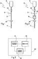
- FIGs. 1 and 2 a fluid transfer system is shown schematically as infusion system 10. While FIGs. 1 and 2 show the fluid transfer system as patient infusion system 10, those of skill in the art will recognize that other fluid transfer systems, such as automatic compounder systems, are within the scope of the present invention.
- the infusion system 10 includes a medication container 12, a catheter 14 for connection to a patient, and a tubing set 16 providing fluid communication between the medication container 12 and the catheter 14.
- the infusion system 10 can be a so-called "gravity-fed" pumpless system as shown in FIG. 1 , or optionally includes an infusion pump 18 for pumping the medication from the container 12 through the tubing set 16 and catheter 14 into a patient as shown in FIG. 2 . While the systems 10 shown in FIGs. 1 and 2 include equipment for delivering a single medication for clarity, those of skill in the art will recognize that an infusion system may include multiple containers, catheters, pumps, and tubing sets.
- the medication container 12 can be, for example, a bag, bottle, syringe, or other standard container used to contain liquid medications. There is no particular restriction regarding what containers may be used.
- a drip chamber 20 is preferably disposed directly downstream from the medication container 12. The drip chamber 20 allows gas to separate from fluid exiting the medication container 12, thus helping to prevent an air embolism, and also helps a clinician estimate the flow rate of the medication by allowing the clinician to count the number of drops of the medication that enter the drip chamber 20 in a given period of time.
- the catheter 14 can be any standard equipment for use with a patient.
- the catheter 14 may be, for example, a temporary catheter inserted into a peripheral vein, a peripherally inserted central catheter, a central venous catheter, or other catheter known to those in the art.
- the tubing set 16 is any standard tubing set used to connect the medication container 12 to the catheter 14.
- the infusion pump 18 is any known pump used to administer fluid intravenously.
- the pump 18 is used to help regulate fluid flow through the system 10, and may be used to vary an infusion rate based on, for example time and/or patient demand.
- the pump 18 is positioned between the drip chamber 20 and the catheter 14, and may include one or more "channels," with each channel used to regulate fluid flow from a distinct medication container through a distinct tubing set.
- FIGs. 1 and 2 each show at least one acoustic receiver 22 connected to an exterior surface of the tubing set 16.
- the acoustic receiver 22 is a device capable of detecting acoustic waves transmitted through the tubing set 16.
- the receiver 22 is preferably removably secured to the tubing set 16, such that a clinician can position the receiver at any desired position along the length of the tubing set, and can move the receiver from one tubing set to another as desired.
- FIG. 2 shows the acoustic receiver 22 as a separate device, artisans will recognize that the receiver can optionally be incorporated into the pump 18 as an integrated acoustic receiver disposed at one or both of the upstream and downstream sides of the pump without departing from the scope of the invention.
- the receiver 22 is optionally formed as an integral portion of the tubing set 16, disposed near the medication container 12 and/or near the catheter 14.
- the receiver 22 is optionally formed as an integral portion of the infusion system 10, including the medication container 12 and/or the catheter 14.
- the acoustic receiver 22 includes a sensor 24, an indicator 26, and a power source 28.
- the sensor 24, such as a vibration sensor is disposed in contact with the tubing set 16, and is used to detect an acoustic vibratory signal transmitted through the tubing set 16.
- the sensor 24 is a transducer capable of converting vibrations from the tubing set 16 into an electrical signal.
- the sensor 24 is optionally a microphone such as a contact microphone or other piezoelectric device.
- the sensor 24 is electrically connected to the indicator 26, which provides at least one of an audio and a visual or other indication when the sensor 24 detects sound waves.
- the indicator 26 is preferably a small indicator light such as a light emitting diode, a small loudspeaker capable of emitting an audible tone, or other device capable of providing an observable signal to a clinician.
- the power source 28 provides power to the receiver 22.
- the power source 28 is preferably a compact portable power source such as a battery.
- other sources such as a connection to mains power, photovoltaic panels, and the like may be used without departing from the scope of the invention.
- the receiver 22 is preferably removably connected to the tubing itself and/or any component of the tubing set 16, such as the drip chamber 20 and/or access ports.
- the receiver 22 can be connected to other portions of the infusion system 10, including the medication container 12 or the catheter 14. This connection is formed by, for example a spring-biased clamp.
- the force exerted on the tubing set 16 by the receiver 22 is desirably sufficient for maintaining steady contact between the sensor 24 and the tubing set, so that an accurate reading can be performed.
- the biasing force retaining the receiver 22 in place should not be so strong as to occlude the tubing set 16.
- the signal sensed by the acoustic receiver 22 is preferably provided, for example, by a signal transmitter 30 preferably removably connected to the tubing set.
- the transmitter 30 may be any device capable of producing a vibratory acoustic signal, preferably an ultrasound signal having a frequency greater than 20 kHz.
- the transmitter 30 includes a piezoelectric device configured for generating ultrasonic acoustic vibrations.
- the transmitter 30 can be a separate device, or optionally can be incorporated into the tubing set 16.
- the transmitter 30 can optionally be attached to or formed integrally with other elements of the infusion system 10, including the medication container 12 and/or the catheter 14. As shown in FIG.
- the transmitter 30 can also optionally be incorporated into the infusion pump 18 as an integrated signal transmitter 18a. While FIG. 5 shows integrated signal transmitter 18a disposed on the downstream side of the pump 18, those of skill in the art will recognize that an integrated signal transmitter can be disposed at one or both of the upstream and downstream sides without departing from the scope of the invention.
- a pumping mechanism of the infusion pump 18 can be the signal transmitter 30. While in the depicted embodiment, the signal transmitter 30 is separate from the acoustic receiver 22, it is also contemplated that the acoustic receiver 22 is also optionally capable of generating an acoustic vibratory signal, thus operating as a signal transmitter/receiver or "transceiver".
- the vibratory signal may be generated manually, for example by a clinician tapping the tubing set using, for example, a finger or other implement.
- the vibratory acoustic signal is preferably applied at a location 13 distant from the receiver 22, so that opposite ends of the tubing set 16 are determined to be continuous.
- FIG. 1 shows the vibratory signal can be applied to the tubing set 16 at the location 13 disposed proximate to the medication container 12, while the receiver 22 is positioned proximate to the catheter 14;
- FIG. 2 shows the vibratory signal applied at a location 13 downstream from the pump 18, with the receiver 22 positioned near the catheter 14;
- FIG 5 shows the vibratory signal applied at the position 13 near the medication bag, with a first receiver 22 positioned upstream of the pump 18.
- a vibratory signal is provided at a first end of the tubing set 16.
- the signal is optionally provided continuously or intermittently (e.g., a pulsed signal).
- the acoustic receiver 22 is then systematically connected to each of a plurality of candidate tubes at a second end of the infusion system 10, until the vibratory signal is detected by the sensor 24 at the tube which is in fluid communication with the tube coupled to the signal transmitter.
- FIG. 4 shows a graph indicating receipt of a pulsed signal by the sensor 24, such as by the signal transmitter 30 or by a clinician tapping on the tubing set 16.
- the indicator 26 provides an indication to the clinician that the signal has been received. The clinician then knows that the tubing section 16 to which the acoustic receiver 22 is connected is continuous with the tubing section to which the vibratory signal is provided.
- the infusion pump 18 may dampen the provided vibratory signal sufficiently that a signal provided on an upstream side of the pump cannot be accurately detected on a downstream side of the pump (or vice versa).
- One method of accommodating the dampening factor of the infusion pump 18 is to use a two-step process, whereby the receiver 22 is initially placed on the tubing set 16 near the catheter 14, and a vibratory signal is systematically transmitted from the location 13 associated with each pump channel output on the downstream side of the pump or pumps (if there are multiple pumps in the infusion system), one by one, until continuity is established on the downstream side of the infusion system.
- a “top down” workflow uses a signal transmitted from the medicine container and received at the pump upstream side, and a signal transmitted from the pump downstream side and received at the catheter.
- a “bottom up” workflow uses a signal transmitted from the catheter and received at the pump downstream side and a signal transmitted from the pump upstream side and received at the medicine container.
- the chart below shows the positioning of the transmitters and receivers with respect to the medication container, pump upstream side, pump downstream side, and catheter: Medication Container Pump Upstream Side Pump Downstream Side Catheter “pump out” Receiver Transmitter Transmitter Receiver “pump in” Transmitter Receiver Receiver Transmitter “top down” Transmitter Receiver Transmitter Receiver “bottom up” Receiver Transmitter Receiver Transmitter
- a system that allows for the flexibility to determine continuity in whichever way a clinician prefers is advantageous in that it encourages the clinicians to use the equipment, reducing the propensity for errors in line tracing and increasing the speed at which a line tracing can be performed.
- the infusion system 10 optionally includes a relay 32 having the acoustic receiver 22 electrically coupled to the signal transmitter 30 via a wired or wireless connection.
- the relay is disposed such that the receiver and the transmitter are on opposite sides of the pump (i.e., the receiver 22 is disposed upstream, while the transmitter 30 is disposed downstream, or vice versa).
- an acoustic signal is provided to the tubing set 16 on the side of the pump that includes the receiver.
- the receiver 22 receives the provided signal, a corresponding signal is generated by the electrically coupled signal transmitter 30.
- the dampening effect of the pump 18 is negated.
- the signal receiver 22 and the signal transmitter 30 may communicate with one another, either wirelessly or via wired connection.
- the transmitter 30 preferably transmits information regarding one or more characteristics of the transmitted acoustic vibration to the receiver 22. Such characteristics preferably include one or more of signal frequency (or range of frequencies), signal amplitude (or range of amplitudes), signal timing, a particular signal pattern to be transmitted, or other characteristics identifying the signal.
- the receiver 22 can discriminate between a received signal from the transmitter 30 and noise or other extraneous vibrations in the tubing caused by, for example cross-talk between numerous transmitters and receivers in a complex infusion system, incidental contact between multiple tubes of an infusion system, vibrations induced by a pump 18, or other sources of vibration present within system 10.
- the receiver 22 compares the signal received at the sensor 24 with the one or more signal characteristics and, if the received signal matches the characteristics, indicates that the signal is received via the indicator 26.
Landscapes
- Health & Medical Sciences (AREA)
- Heart & Thoracic Surgery (AREA)
- Life Sciences & Earth Sciences (AREA)
- General Health & Medical Sciences (AREA)
- Engineering & Computer Science (AREA)
- Anesthesiology (AREA)
- Hematology (AREA)
- Biomedical Technology (AREA)
- Animal Behavior & Ethology (AREA)
- Public Health (AREA)
- Veterinary Medicine (AREA)
- Physics & Mathematics (AREA)
- Vascular Medicine (AREA)
- Pulmonology (AREA)
- General Physics & Mathematics (AREA)
- Chemical & Material Sciences (AREA)
- Analytical Chemistry (AREA)
- Biochemistry (AREA)
- Immunology (AREA)
- Pathology (AREA)
- Acoustics & Sound (AREA)
- Mining & Mineral Resources (AREA)
- Geology (AREA)
- Fluid Mechanics (AREA)
- Environmental & Geological Engineering (AREA)
- Geophysics (AREA)
- General Life Sciences & Earth Sciences (AREA)
- Geochemistry & Mineralogy (AREA)
- Infusion, Injection, And Reservoir Apparatuses (AREA)
- Indicating Or Recording The Presence, Absence, Or Direction Of Movement (AREA)
- Measurement Of Velocity Or Position Using Acoustic Or Ultrasonic Waves (AREA)
Claims (13)
- Akustisches Liniennachverfolgungssystem zum Nachverfolgen einer Fluidübertragungssystemschlauchlinie, wobei das Nachverfolgungssystem Folgendes umfasst:einen ersten akustischen Empfänger (22), der betriebsfähig mit der Schlauchlinie verbindbar ist und zum Empfangen eines vibrierenden Signals konfiguriert ist, wobei der erste akustische Empfänger Folgendes enthält: einen ersten Schwingungssensor (24), angeordnet, um die Schlauchlinie zu berühren, wobei der erste Schwingungssensor zum Nachweisen einer Schwingung auf der Oberfläche der Schlauchlinie, verursacht durch das schwingende Signal konfiguriert ist;einen Signalüberträger (30), der das Schlauchset (16) wirkberührt und mit dem ersten akustischen Empfänger (22) elektrisch gekoppelt (32) ist, wobei der Signalüberträger zum Erzeugen einer akustischen Schwingung in der Schlauchlinie konfiguriert ist, wenn der erste Schwingungssensor ein vibrierendes Signal nachweist; undeinen zweiten akustischen Empfänger (22), der mit der Schlauchlinie verbindbar ist und zum Empfangen der akustischen Schwingungen, die von dem Signalüberträger erzeugt werden, konfiguriert ist, wobei der zweite akustische Empfänger Folgendes enthält:einen zweiten Schwingungssensor (24), angeordnet, um die Schlauchlinie zu berühren, wobei der zweite Schwingungssensor zum Nachweisen von Schwingungen auf der Oberfläche der Schlauchlinie, verursacht durch die akustischen Schwingungen, konfiguriert ist; undein Anzeiger, der einen Audio- und/oder visuellen Hinweis herstellt, wenn der zweite Schwingungssensor das vibrierende Signal nachweist;wobei der erste akustische Empfänger der Infusionspumpe (18) und dem Signalüberträger der Infusionspumpe nachgelagert ist, um Dämpfen des Schwingungssignals durch die Infusionspumpe zu verringern.
- Akustisches Liniennachverfolgungssystem nach Anspruch 1, wobei jeder der Schwingungssensoren eine piezoelektrische Vorrichtung ist.
- Akustisches Liniennachverfolgungssystem nach Anspruch 1, wobei jeder Schwingungssensor ein Mikrophon ist.
- Akustisches Liniennachverfolgungssystem nach Anspruch 1, wobei der Anzeiger eine Leuchtdiode ist, und wobei die Diode Licht ausstrahlt, wenn der zweite Schwingungssensor ein vibrierendes Signal nachweist.
- Akustisches Liniennachverfolgungssystem nach Anspruch 1, wobei der Anzeiger ein Lautsprecher ist, und wobei der Lautsprecher einen hörbaren Ton ausstrahlt, wenn der zweite Schwingungssensor das vibrierende Signal nachweist.
- Akustisches Liniennachverfolgungssystem nach Anspruch 1, wobei der Signalüberträger eine piezoelektrische Vorrichtung enthält, die zum Erzeugen von akustischen Ultraschallschwingungen konfiguriert ist.
- Akustisches Liniennachverfolgungssystem nach Anspruch 1, wobei der Signalüberträger zum Kommunizieren eines oder mehrerer Merkmale des schwingenden Signals an den zweiten akustischen Empfänger konfiguriert ist.
- Akustisches Liniennachverfolgungssystem nach Anspruch 7, wobei das eine oder die mehreren Merkmale eines einer Frequenz, eines Frequenzbereichs, einer Amplitude, eines Amplitudenbereichs, eines Signalzeitpunkts und/oder eines besonderen Signalmusters ist.
- Akustisches Liniennachverfolgungssystem nach Anspruch 1 zum Verifizieren von Kontinuität eines Schlauchsets in einem Infusionssystem, wobei das Liniennachverfolgungssystem Folgendes umfasst:eine Infusionspumpe;einen ersten akustischen Empfänger, der mit der Schlauchlinie verbindbar ist und zum Empfangen eines schwingenden Signals konfiguriert ist, wobei der erste akustische Empfänger einen ersten Schwingungssensor, angeordnet, um die Schlaulinie zu berühren, enthält, wobei der erste Schwingungssensor zum Nachweisen von Schwingung auf der Oberfläche der Schlauchlinie, verursacht durch das schwingende Signal, konfiguriert ist;einen Signalüberträger innerhalb eines Gehäuses der Infusionspumpe und das Schlauchset wirkberührend und mit dem ersten akustischen Empfänger elektrisch gekoppelt, wobei der Signalüberträger zum Erzeugen von akustischen Schwingungen in der Schlauchlinie konfiguriert ist, wenn der erste Schwingungssensor ein schwingendes Signal nachweist; undeinen zweiten akustischen Empfänger, der mit der Schlauchlinie verbunden ist und zum Empfangen der akustischen Schwingungen, erzeugt durch den Signalüberträger, konfiguriert ist, wobei der zweite akustische Empfänger Folgendes enthält:einen zweiten Schwingungssensor, angeordnet um die Schlauchlinie zu berühren, wobei der zweite Schwingungssensor zum Nachweisen von Schwingungen auf der Oberfläche der Schlauchlinie, verursacht durch die akustischen Schwingungen, konfiguriert ist; undeinen Anzeiger, der einen Audio- und/oder visuellen Hinweis herstellt, wenn der zweite Schwingungssensor Schwingungen nachweist;wobei der erste akustische Empfänger und der Signalüberträger durch die Infusionspumpe getrennt sind, um Dämpfen des schwingenden Signals durch die Infusionspumpe zu verringern.
- Akustisches Liniennachverfolgungssystem nach Anspruch 9, wobei jeder der Schwingungssensoren eine piezoelektrische Vorrichtung ist.
- Akustisches Liniennachverfolgungssystem nach Anspruch 9, wobei jeder Schwingungssensor ein Mikrophon ist.
- Akustisches Liniennachverfolgungssystem nach Anspruch 9, wobei der Anzeiger eine Leuchtdiode ist, und wobei die Leuchtdiode Licht ausstrahlt, wenn der zweite Schwingungssensor das schwingende Signal nachweist.
- Akustisches Liniennachverfolgungssystem nach Anspruch 9, wobei der Signalüberträger eine piezoelektrische Vorrichtung enthält, die zum Erzeugen von akustischen Ultraschallschwingungen konfiguriert ist.
Priority Applications (1)
| Application Number | Priority Date | Filing Date | Title |
|---|---|---|---|
| EP18168082.8A EP3366334A1 (de) | 2013-03-15 | 2014-03-13 | Akustisches schlauchverfolgungssystem und -methode für ein fluidtransfersystem |
Applications Claiming Priority (2)
| Application Number | Priority Date | Filing Date | Title |
|---|---|---|---|
| US13/837,417 US9359885B2 (en) | 2013-03-15 | 2013-03-15 | Acoustic line tracing system and method for fluid transfer system |
| PCT/US2014/025685 WO2014151415A2 (en) | 2013-03-15 | 2014-03-13 | Acoustic line tracing system and method for fluid transfer system |
Related Child Applications (1)
| Application Number | Title | Priority Date | Filing Date |
|---|---|---|---|
| EP18168082.8A Division EP3366334A1 (de) | 2013-03-15 | 2014-03-13 | Akustisches schlauchverfolgungssystem und -methode für ein fluidtransfersystem |
Publications (2)
| Publication Number | Publication Date |
|---|---|
| EP2968741A2 EP2968741A2 (de) | 2016-01-20 |
| EP2968741B1 true EP2968741B1 (de) | 2018-05-09 |
Family
ID=50549452
Family Applications (2)
| Application Number | Title | Priority Date | Filing Date |
|---|---|---|---|
| EP14719458.3A Not-in-force EP2968741B1 (de) | 2013-03-15 | 2014-03-13 | Akustisches schlauchverfolgungssystem für ein fluidtransfersystem |
| EP18168082.8A Withdrawn EP3366334A1 (de) | 2013-03-15 | 2014-03-13 | Akustisches schlauchverfolgungssystem und -methode für ein fluidtransfersystem |
Family Applications After (1)
| Application Number | Title | Priority Date | Filing Date |
|---|---|---|---|
| EP18168082.8A Withdrawn EP3366334A1 (de) | 2013-03-15 | 2014-03-13 | Akustisches schlauchverfolgungssystem und -methode für ein fluidtransfersystem |
Country Status (11)
| Country | Link |
|---|---|
| US (3) | US9359885B2 (de) |
| EP (2) | EP2968741B1 (de) |
| JP (1) | JP6401775B2 (de) |
| KR (1) | KR101990180B1 (de) |
| CN (1) | CN105120923B (de) |
| AR (1) | AR096017A1 (de) |
| AU (1) | AU2014234996B2 (de) |
| CA (1) | CA2905938A1 (de) |
| ES (1) | ES2682472T3 (de) |
| MX (2) | MX370568B (de) |
| WO (1) | WO2014151415A2 (de) |
Cited By (2)
| Publication number | Priority date | Publication date | Assignee | Title |
|---|---|---|---|---|
| US11167081B2 (en) | 2016-06-16 | 2021-11-09 | Smiths Medical Asd, Inc. | Assemblies and methods for infusion pump system administration sets |
| US11801342B2 (en) | 2017-07-19 | 2023-10-31 | Smiths Medical Asd, Inc. | Housing arrangements for infusion pumps |
Families Citing this family (18)
| Publication number | Priority date | Publication date | Assignee | Title |
|---|---|---|---|---|
| US9707375B2 (en) | 2011-03-14 | 2017-07-18 | Rochester Medical Corporation, a subsidiary of C. R. Bard, Inc. | Catheter grip and method |
| KR102216573B1 (ko) | 2012-09-06 | 2021-02-18 | 백스터 인터내셔널 인코포레이티드 | 주입 맵을 포함하는 환자 정보 소프트웨어 시스템 |
| KR102197274B1 (ko) | 2012-11-13 | 2021-01-05 | 백스터 인터내셔널 인코포레이티드 | 주입 라인 관리 시스템 |
| US9872969B2 (en) | 2012-11-20 | 2018-01-23 | Rochester Medical Corporation, a subsidiary of C.R. Bard, Inc. | Catheter in bag without additional packaging |
| US9359885B2 (en) * | 2013-03-15 | 2016-06-07 | Baxter International Inc. | Acoustic line tracing system and method for fluid transfer system |
| CA2891750A1 (en) * | 2014-05-21 | 2015-11-21 | Weatherford/Lamb, Inc. | Dart detector for wellbore tubular cementation |
| KR101879934B1 (ko) * | 2016-05-31 | 2018-07-19 | 중앙대학교 산학협력단 | 혈관 탐지 장치 |
| US10064991B2 (en) | 2016-06-24 | 2018-09-04 | MJ Stewart Investments, LLC | Infusion line systems |
| AU2017311546B2 (en) * | 2016-08-09 | 2022-09-15 | F. Hoffmann-La Roche Ag | Ambulatory infusion device |
| KR101914470B1 (ko) * | 2016-08-24 | 2019-01-07 | 노효정 | 수액 감지 시스템 |
| DE102017114800A1 (de) | 2017-07-03 | 2019-01-03 | Fresenius Medical Care Deutschland Gmbh | Vorrichtung zur Erkennung des Konnektionszustandes |
| EP3675779B1 (de) * | 2017-09-19 | 2025-09-10 | C. R. Bard, Inc. | Vorrichtung zur überbrückung von harnkathetern, systeme und verfahren dafür |
| EP4176281A1 (de) * | 2020-07-02 | 2023-05-10 | Fresenius Medical Care Holdings, Inc. | System und verfahren zur erkennung der loslösung einer venösen nadel |
| US12288618B2 (en) * | 2020-08-14 | 2025-04-29 | Carefusion 303, Inc. | Electronic tags for associating and identifying intravenous administration lines |
| CN119173446A (zh) | 2022-03-08 | 2024-12-20 | 赤盾医疗有限公司 | 机器人药物制备系统中的流体转移站 |
| US20230398313A1 (en) * | 2022-06-08 | 2023-12-14 | Micrel Medical Devices S.A. | Air in line detector for medical infusion pumps |
| WO2024086672A1 (en) * | 2022-10-18 | 2024-04-25 | Orion Innovations Inc. | Multi-component communication system for infusion line identification |
| WO2025090713A1 (en) | 2023-10-27 | 2025-05-01 | Fresenius Medical Care Holdings, Inc. | Needle dislodgement detection systems and methods |
Family Cites Families (44)
| Publication number | Priority date | Publication date | Assignee | Title |
|---|---|---|---|---|
| US4526404A (en) | 1983-04-29 | 1985-07-02 | Vazquez Richard M | Container for clinical product |
| US5048870A (en) | 1989-06-01 | 1991-09-17 | Pharmedix | Multipart flag label for pharmaceutical products |
| US5180287A (en) * | 1990-03-15 | 1993-01-19 | Abbott Laboratories | Method for monitoring fluid flow from a volumetric pump |
| US5039279A (en) * | 1990-03-15 | 1991-08-13 | Abbott Laboratories | Sensor for detecting fluid flow from a positive displacement pump |
| US5090779A (en) | 1990-08-27 | 1992-02-25 | Rockwell International Corporation | Acoustic signal transmission between a tractor and trailer within the air brake system |
| US5641892A (en) * | 1995-06-07 | 1997-06-24 | Deka Products Limited Partnership | Intravenous-line air-detection system |
| US5329927A (en) | 1993-02-25 | 1994-07-19 | Echo Cath, Inc. | Apparatus and method for locating an interventional medical device with a ultrasound color imaging system |
| CA2132164A1 (en) | 1993-09-16 | 1995-03-17 | Richard W. Foote | Pharmaceutical label and record system |
| US6442105B1 (en) * | 1995-02-09 | 2002-08-27 | Baker Hughes Incorporated | Acoustic transmission system |
| US5799981A (en) | 1995-05-12 | 1998-09-01 | Global Healthcomm, Inc. | Pharmaceutical marketing device and system |
| US6035568A (en) | 1996-12-11 | 2000-03-14 | Pharmagraphics (Midwest), L.L.C. | Primary label with removable self-adhesive labels |
| US5782495A (en) | 1996-01-11 | 1998-07-21 | Westlake Ventures, L.L.C. | Hanger label |
| US5958536A (en) | 1997-03-06 | 1999-09-28 | The Challenge Printing Company | Self-adhesive label with detachable sticker |
| US5974708A (en) | 1997-08-22 | 1999-11-02 | Trauma Technologies, Llc | Intravenous line identification system |
| US6468242B1 (en) * | 1998-03-06 | 2002-10-22 | Baxter International Inc. | Medical apparatus with patient data recording |
| US20020056989A1 (en) | 1998-04-02 | 2002-05-16 | Lewis-Leander | Medication i.v. warning label |
| US6142008A (en) * | 1998-06-12 | 2000-11-07 | Abbott Laboratories | Air bubble sensor |
| US6410111B1 (en) | 1998-09-10 | 2002-06-25 | Ncr Corporation | Selective release label sheet |
| US20020077582A1 (en) | 1999-09-03 | 2002-06-20 | Baxter International Inc. | Blood processing systems and methods that assess and respond to real or potential vein occlusion conditions |
| US7933780B2 (en) | 1999-10-22 | 2011-04-26 | Telaric, Llc | Method and apparatus for controlling an infusion pump or the like |
| US7197932B2 (en) | 2000-09-04 | 2007-04-03 | The Nippon Signal Co, Ltd. | Failure detecting system |
| US7455662B2 (en) | 2001-05-14 | 2008-11-25 | Kraushaar Timothy Y | IV administration set identification system |
| GB0211662D0 (en) | 2002-05-21 | 2002-07-03 | Innovision Res & Tech Plc | System |
| US8317770B2 (en) * | 2006-04-06 | 2012-11-27 | Medtronic, Inc. | Systems and methods of identifying catheter malfunctions using pressure sensing |
| US8571881B2 (en) | 2004-11-09 | 2013-10-29 | Spectrum Dynamics, Llc | Radiopharmaceutical dispensing, administration, and imaging |
| CA2561641A1 (en) | 2004-04-02 | 2005-10-20 | Plasiatek, Llc | Ultrasonic placement and monitoring of an endotracheal tube |
| US7092797B2 (en) * | 2004-05-25 | 2006-08-15 | Sherwood Services Ag | Flow monitoring system for a flow control apparatus |
| JP4417183B2 (ja) | 2004-06-22 | 2010-02-17 | 株式会社トーショー | 薬品管理装置および薬品管理システム |
| US8266878B2 (en) | 2004-10-01 | 2012-09-18 | Edge Medical Properties, Llc | System and method for verifying and assembling a multiple prescription package |
| JP5113742B2 (ja) | 2005-05-10 | 2013-01-09 | ケアフュージョン 303、インコーポレイテッド | 多重化rfid質問機パネルを備える投薬安全システム |
| US20070088286A1 (en) | 2005-08-03 | 2007-04-19 | Brier Arnold M | Identification system for intravenous tubing |
| GB2432121A (en) | 2005-11-10 | 2007-05-16 | Link Sure Ltd | Fluid connection verification apparatus |
| US20070233035A1 (en) | 2006-03-28 | 2007-10-04 | Hospira, Inc. | Medication administration and management system and method |
| WO2008008281A2 (en) * | 2006-07-07 | 2008-01-17 | Proteus Biomedical, Inc. | Smart parenteral administration system |
| US8645155B2 (en) | 2006-08-18 | 2014-02-04 | General Electric Company | Automatic loading of medical data in integrated information system |
| US7981082B2 (en) * | 2007-08-21 | 2011-07-19 | Hospira, Inc. | System and method for reducing air bubbles in a fluid delivery line |
| US8554579B2 (en) | 2008-10-13 | 2013-10-08 | Fht, Inc. | Management, reporting and benchmarking of medication preparation |
| MX2012002900A (es) | 2009-09-09 | 2012-06-25 | Honeywell Int Inc | Compuestos monoclorotrifluoropropeno y composiciones y metodos para utilizarlos-. |
| US8291337B2 (en) | 2009-09-22 | 2012-10-16 | Cerner Innovation, Inc. | Infusion management |
| US8597271B2 (en) | 2012-01-17 | 2013-12-03 | Pharmedium Services, Llc | Intravenous bag/line safety device |
| KR102216573B1 (ko) | 2012-09-06 | 2021-02-18 | 백스터 인터내셔널 인코포레이티드 | 주입 맵을 포함하는 환자 정보 소프트웨어 시스템 |
| US20150272828A1 (en) | 2012-10-05 | 2015-10-01 | The Board Of Trustees Of The University Of Illinois | Intravenous bag labeling system |
| KR102197274B1 (ko) | 2012-11-13 | 2021-01-05 | 백스터 인터내셔널 인코포레이티드 | 주입 라인 관리 시스템 |
| US9359885B2 (en) * | 2013-03-15 | 2016-06-07 | Baxter International Inc. | Acoustic line tracing system and method for fluid transfer system |
-
2013
- 2013-03-15 US US13/837,417 patent/US9359885B2/en not_active Expired - Fee Related
-
2014
- 2014-03-13 EP EP14719458.3A patent/EP2968741B1/de not_active Not-in-force
- 2014-03-13 JP JP2016501942A patent/JP6401775B2/ja not_active Expired - Fee Related
- 2014-03-13 ES ES14719458.3T patent/ES2682472T3/es active Active
- 2014-03-13 CA CA2905938A patent/CA2905938A1/en not_active Abandoned
- 2014-03-13 MX MX2015013068A patent/MX370568B/es active IP Right Grant
- 2014-03-13 CN CN201480015543.9A patent/CN105120923B/zh not_active Expired - Fee Related
- 2014-03-13 WO PCT/US2014/025685 patent/WO2014151415A2/en not_active Ceased
- 2014-03-13 KR KR1020157029185A patent/KR101990180B1/ko not_active Expired - Fee Related
- 2014-03-13 AU AU2014234996A patent/AU2014234996B2/en not_active Ceased
- 2014-03-13 EP EP18168082.8A patent/EP3366334A1/de not_active Withdrawn
- 2014-03-14 AR ARP140101159A patent/AR096017A1/es active IP Right Grant
-
2015
- 2015-09-14 MX MX2019010496A patent/MX2019010496A/es unknown
-
2016
- 2016-04-20 US US15/133,483 patent/US9656052B2/en not_active Expired - Fee Related
-
2017
- 2017-04-14 US US15/488,003 patent/US10092696B2/en not_active Expired - Fee Related
Non-Patent Citations (1)
| Title |
|---|
| None * |
Cited By (2)
| Publication number | Priority date | Publication date | Assignee | Title |
|---|---|---|---|---|
| US11167081B2 (en) | 2016-06-16 | 2021-11-09 | Smiths Medical Asd, Inc. | Assemblies and methods for infusion pump system administration sets |
| US11801342B2 (en) | 2017-07-19 | 2023-10-31 | Smiths Medical Asd, Inc. | Housing arrangements for infusion pumps |
Also Published As
| Publication number | Publication date |
|---|---|
| CA2905938A1 (en) | 2014-09-25 |
| MX2015013068A (es) | 2016-05-31 |
| KR101990180B1 (ko) | 2019-06-17 |
| MX370568B (es) | 2019-12-17 |
| WO2014151415A3 (en) | 2014-11-13 |
| US9656052B2 (en) | 2017-05-23 |
| ES2682472T3 (es) | 2018-09-20 |
| KR20150132397A (ko) | 2015-11-25 |
| US20160228688A1 (en) | 2016-08-11 |
| CN105120923A (zh) | 2015-12-02 |
| CN105120923B (zh) | 2019-02-22 |
| AU2014234996B2 (en) | 2017-12-21 |
| US20140262252A1 (en) | 2014-09-18 |
| US20170216522A1 (en) | 2017-08-03 |
| JP6401775B2 (ja) | 2018-10-10 |
| US10092696B2 (en) | 2018-10-09 |
| MX2019010496A (es) | 2019-10-15 |
| AR096017A1 (es) | 2015-12-02 |
| US9359885B2 (en) | 2016-06-07 |
| JP2016518157A (ja) | 2016-06-23 |
| EP3366334A1 (de) | 2018-08-29 |
| EP2968741A2 (de) | 2016-01-20 |
| AU2014234996A1 (en) | 2015-10-15 |
| WO2014151415A2 (en) | 2014-09-25 |
Similar Documents
| Publication | Publication Date | Title |
|---|---|---|
| EP2968741B1 (de) | Akustisches schlauchverfolgungssystem für ein fluidtransfersystem | |
| JP7822356B2 (ja) | イベント監視のためのシステム、方法、および製品 | |
| US5586085A (en) | Container and adaptor for use with fluid volume sensor | |
| US12523506B2 (en) | Flow sensor system including transmissive connection having bonding adhesive between the transducers and the fittings | |
| US11857760B2 (en) | Fluid sensor | |
| CN107949408B (zh) | 具有吸收器的流量传感器系统 | |
| CN116056739B (zh) | 用于关联和识别静脉给药管线的电子标签 | |
| US20200390951A1 (en) | Intravenous System Including Pump, Vascular Access Device And Securement Device And Methods Thereof | |
| US20180147346A1 (en) | Infusion system and method for integrity monitoring of an infusion system | |
| EP2968746A1 (de) | Infusionsschlauchverfolgungssystem mit einem schwingungserzeuger und einem schwingungssensor |
Legal Events
| Date | Code | Title | Description |
|---|---|---|---|
| PUAI | Public reference made under article 153(3) epc to a published international application that has entered the european phase |
Free format text: ORIGINAL CODE: 0009012 |
|
| 17P | Request for examination filed |
Effective date: 20151005 |
|
| AK | Designated contracting states |
Kind code of ref document: A2 Designated state(s): AL AT BE BG CH CY CZ DE DK EE ES FI FR GB GR HR HU IE IS IT LI LT LU LV MC MK MT NL NO PL PT RO RS SE SI SK SM TR |
|
| AX | Request for extension of the european patent |
Extension state: BA ME |
|
| DAX | Request for extension of the european patent (deleted) | ||
| GRAP | Despatch of communication of intention to grant a patent |
Free format text: ORIGINAL CODE: EPIDOSNIGR1 |
|
| STAA | Information on the status of an ep patent application or granted ep patent |
Free format text: STATUS: GRANT OF PATENT IS INTENDED |
|
| INTG | Intention to grant announced |
Effective date: 20171221 |
|
| GRAS | Grant fee paid |
Free format text: ORIGINAL CODE: EPIDOSNIGR3 |
|
| GRAA | (expected) grant |
Free format text: ORIGINAL CODE: 0009210 |
|
| STAA | Information on the status of an ep patent application or granted ep patent |
Free format text: STATUS: THE PATENT HAS BEEN GRANTED |
|
| AK | Designated contracting states |
Kind code of ref document: B1 Designated state(s): AL AT BE BG CH CY CZ DE DK EE ES FI FR GB GR HR HU IE IS IT LI LT LU LV MC MK MT NL NO PL PT RO RS SE SI SK SM TR |
|
| REG | Reference to a national code |
Ref country code: GB Ref legal event code: FG4D |
|
| REG | Reference to a national code |
Ref country code: CH Ref legal event code: EP Ref country code: AT Ref legal event code: REF Ref document number: 996982 Country of ref document: AT Kind code of ref document: T Effective date: 20180515 |
|
| REG | Reference to a national code |
Ref country code: IE Ref legal event code: FG4D |
|
| REG | Reference to a national code |
Ref country code: DE Ref legal event code: R096 Ref document number: 602014025207 Country of ref document: DE |
|
| REG | Reference to a national code |
Ref country code: NL Ref legal event code: MP Effective date: 20180509 |
|
| REG | Reference to a national code |
Ref country code: ES Ref legal event code: FG2A Ref document number: 2682472 Country of ref document: ES Kind code of ref document: T3 Effective date: 20180920 |
|
| REG | Reference to a national code |
Ref country code: LT Ref legal event code: MG4D |
|
| PG25 | Lapsed in a contracting state [announced via postgrant information from national office to epo] |
Ref country code: LT Free format text: LAPSE BECAUSE OF FAILURE TO SUBMIT A TRANSLATION OF THE DESCRIPTION OR TO PAY THE FEE WITHIN THE PRESCRIBED TIME-LIMIT Effective date: 20180509 Ref country code: SE Free format text: LAPSE BECAUSE OF FAILURE TO SUBMIT A TRANSLATION OF THE DESCRIPTION OR TO PAY THE FEE WITHIN THE PRESCRIBED TIME-LIMIT Effective date: 20180509 Ref country code: NO Free format text: LAPSE BECAUSE OF FAILURE TO SUBMIT A TRANSLATION OF THE DESCRIPTION OR TO PAY THE FEE WITHIN THE PRESCRIBED TIME-LIMIT Effective date: 20180809 Ref country code: BG Free format text: LAPSE BECAUSE OF FAILURE TO SUBMIT A TRANSLATION OF THE DESCRIPTION OR TO PAY THE FEE WITHIN THE PRESCRIBED TIME-LIMIT Effective date: 20180809 Ref country code: FI Free format text: LAPSE BECAUSE OF FAILURE TO SUBMIT A TRANSLATION OF THE DESCRIPTION OR TO PAY THE FEE WITHIN THE PRESCRIBED TIME-LIMIT Effective date: 20180509 |
|
| PG25 | Lapsed in a contracting state [announced via postgrant information from national office to epo] |
Ref country code: GR Free format text: LAPSE BECAUSE OF FAILURE TO SUBMIT A TRANSLATION OF THE DESCRIPTION OR TO PAY THE FEE WITHIN THE PRESCRIBED TIME-LIMIT Effective date: 20180810 Ref country code: LV Free format text: LAPSE BECAUSE OF FAILURE TO SUBMIT A TRANSLATION OF THE DESCRIPTION OR TO PAY THE FEE WITHIN THE PRESCRIBED TIME-LIMIT Effective date: 20180509 Ref country code: RS Free format text: LAPSE BECAUSE OF FAILURE TO SUBMIT A TRANSLATION OF THE DESCRIPTION OR TO PAY THE FEE WITHIN THE PRESCRIBED TIME-LIMIT Effective date: 20180509 Ref country code: NL Free format text: LAPSE BECAUSE OF FAILURE TO SUBMIT A TRANSLATION OF THE DESCRIPTION OR TO PAY THE FEE WITHIN THE PRESCRIBED TIME-LIMIT Effective date: 20180509 Ref country code: HR Free format text: LAPSE BECAUSE OF FAILURE TO SUBMIT A TRANSLATION OF THE DESCRIPTION OR TO PAY THE FEE WITHIN THE PRESCRIBED TIME-LIMIT Effective date: 20180509 |
|
| REG | Reference to a national code |
Ref country code: AT Ref legal event code: MK05 Ref document number: 996982 Country of ref document: AT Kind code of ref document: T Effective date: 20180509 |
|
| PG25 | Lapsed in a contracting state [announced via postgrant information from national office to epo] |
Ref country code: AT Free format text: LAPSE BECAUSE OF FAILURE TO SUBMIT A TRANSLATION OF THE DESCRIPTION OR TO PAY THE FEE WITHIN THE PRESCRIBED TIME-LIMIT Effective date: 20180509 Ref country code: DK Free format text: LAPSE BECAUSE OF FAILURE TO SUBMIT A TRANSLATION OF THE DESCRIPTION OR TO PAY THE FEE WITHIN THE PRESCRIBED TIME-LIMIT Effective date: 20180509 Ref country code: PL Free format text: LAPSE BECAUSE OF FAILURE TO SUBMIT A TRANSLATION OF THE DESCRIPTION OR TO PAY THE FEE WITHIN THE PRESCRIBED TIME-LIMIT Effective date: 20180509 Ref country code: SK Free format text: LAPSE BECAUSE OF FAILURE TO SUBMIT A TRANSLATION OF THE DESCRIPTION OR TO PAY THE FEE WITHIN THE PRESCRIBED TIME-LIMIT Effective date: 20180509 Ref country code: EE Free format text: LAPSE BECAUSE OF FAILURE TO SUBMIT A TRANSLATION OF THE DESCRIPTION OR TO PAY THE FEE WITHIN THE PRESCRIBED TIME-LIMIT Effective date: 20180509 Ref country code: CZ Free format text: LAPSE BECAUSE OF FAILURE TO SUBMIT A TRANSLATION OF THE DESCRIPTION OR TO PAY THE FEE WITHIN THE PRESCRIBED TIME-LIMIT Effective date: 20180509 Ref country code: RO Free format text: LAPSE BECAUSE OF FAILURE TO SUBMIT A TRANSLATION OF THE DESCRIPTION OR TO PAY THE FEE WITHIN THE PRESCRIBED TIME-LIMIT Effective date: 20180509 |
|
| REG | Reference to a national code |
Ref country code: DE Ref legal event code: R097 Ref document number: 602014025207 Country of ref document: DE |
|
| PG25 | Lapsed in a contracting state [announced via postgrant information from national office to epo] |
Ref country code: SM Free format text: LAPSE BECAUSE OF FAILURE TO SUBMIT A TRANSLATION OF THE DESCRIPTION OR TO PAY THE FEE WITHIN THE PRESCRIBED TIME-LIMIT Effective date: 20180509 |
|
| PLBE | No opposition filed within time limit |
Free format text: ORIGINAL CODE: 0009261 |
|
| STAA | Information on the status of an ep patent application or granted ep patent |
Free format text: STATUS: NO OPPOSITION FILED WITHIN TIME LIMIT |
|
| 26N | No opposition filed |
Effective date: 20190212 |
|
| PGFP | Annual fee paid to national office [announced via postgrant information from national office to epo] |
Ref country code: GB Payment date: 20190218 Year of fee payment: 6 Ref country code: DE Payment date: 20190219 Year of fee payment: 6 |
|
| PG25 | Lapsed in a contracting state [announced via postgrant information from national office to epo] |
Ref country code: SI Free format text: LAPSE BECAUSE OF FAILURE TO SUBMIT A TRANSLATION OF THE DESCRIPTION OR TO PAY THE FEE WITHIN THE PRESCRIBED TIME-LIMIT Effective date: 20180509 |
|
| PG25 | Lapsed in a contracting state [announced via postgrant information from national office to epo] |
Ref country code: MC Free format text: LAPSE BECAUSE OF FAILURE TO SUBMIT A TRANSLATION OF THE DESCRIPTION OR TO PAY THE FEE WITHIN THE PRESCRIBED TIME-LIMIT Effective date: 20180509 |
|
| REG | Reference to a national code |
Ref country code: CH Ref legal event code: PL |
|
| PG25 | Lapsed in a contracting state [announced via postgrant information from national office to epo] |
Ref country code: LU Free format text: LAPSE BECAUSE OF NON-PAYMENT OF DUE FEES Effective date: 20190313 Ref country code: AL Free format text: LAPSE BECAUSE OF FAILURE TO SUBMIT A TRANSLATION OF THE DESCRIPTION OR TO PAY THE FEE WITHIN THE PRESCRIBED TIME-LIMIT Effective date: 20180509 |
|
| REG | Reference to a national code |
Ref country code: BE Ref legal event code: MM Effective date: 20190331 |
|
| PG25 | Lapsed in a contracting state [announced via postgrant information from national office to epo] |
Ref country code: CH Free format text: LAPSE BECAUSE OF NON-PAYMENT OF DUE FEES Effective date: 20190331 Ref country code: IE Free format text: LAPSE BECAUSE OF NON-PAYMENT OF DUE FEES Effective date: 20190313 Ref country code: LI Free format text: LAPSE BECAUSE OF NON-PAYMENT OF DUE FEES Effective date: 20190331 |
|
| PG25 | Lapsed in a contracting state [announced via postgrant information from national office to epo] |
Ref country code: BE Free format text: LAPSE BECAUSE OF NON-PAYMENT OF DUE FEES Effective date: 20190331 Ref country code: IT Free format text: LAPSE BECAUSE OF NON-PAYMENT OF DUE FEES Effective date: 20190313 Ref country code: FR Free format text: LAPSE BECAUSE OF NON-PAYMENT OF DUE FEES Effective date: 20190331 |
|
| PG25 | Lapsed in a contracting state [announced via postgrant information from national office to epo] |
Ref country code: TR Free format text: LAPSE BECAUSE OF FAILURE TO SUBMIT A TRANSLATION OF THE DESCRIPTION OR TO PAY THE FEE WITHIN THE PRESCRIBED TIME-LIMIT Effective date: 20180509 |
|
| PG25 | Lapsed in a contracting state [announced via postgrant information from national office to epo] |
Ref country code: MT Free format text: LAPSE BECAUSE OF NON-PAYMENT OF DUE FEES Effective date: 20190313 Ref country code: PT Free format text: LAPSE BECAUSE OF FAILURE TO SUBMIT A TRANSLATION OF THE DESCRIPTION OR TO PAY THE FEE WITHIN THE PRESCRIBED TIME-LIMIT Effective date: 20180910 |
|
| REG | Reference to a national code |
Ref country code: ES Ref legal event code: FD2A Effective date: 20200724 |
|
| REG | Reference to a national code |
Ref country code: DE Ref legal event code: R119 Ref document number: 602014025207 Country of ref document: DE |
|
| PG25 | Lapsed in a contracting state [announced via postgrant information from national office to epo] |
Ref country code: ES Free format text: LAPSE BECAUSE OF NON-PAYMENT OF DUE FEES Effective date: 20190314 |
|
| PG25 | Lapsed in a contracting state [announced via postgrant information from national office to epo] |
Ref country code: DE Free format text: LAPSE BECAUSE OF NON-PAYMENT OF DUE FEES Effective date: 20201001 |
|
| GBPC | Gb: european patent ceased through non-payment of renewal fee |
Effective date: 20200313 |
|
| PG25 | Lapsed in a contracting state [announced via postgrant information from national office to epo] |
Ref country code: GB Free format text: LAPSE BECAUSE OF NON-PAYMENT OF DUE FEES Effective date: 20200313 |
|
| PG25 | Lapsed in a contracting state [announced via postgrant information from national office to epo] |
Ref country code: CY Free format text: LAPSE BECAUSE OF FAILURE TO SUBMIT A TRANSLATION OF THE DESCRIPTION OR TO PAY THE FEE WITHIN THE PRESCRIBED TIME-LIMIT Effective date: 20180509 |
|
| PG25 | Lapsed in a contracting state [announced via postgrant information from national office to epo] |
Ref country code: IS Free format text: LAPSE BECAUSE OF FAILURE TO SUBMIT A TRANSLATION OF THE DESCRIPTION OR TO PAY THE FEE WITHIN THE PRESCRIBED TIME-LIMIT Effective date: 20180909 |
|
| PG25 | Lapsed in a contracting state [announced via postgrant information from national office to epo] |
Ref country code: HU Free format text: LAPSE BECAUSE OF FAILURE TO SUBMIT A TRANSLATION OF THE DESCRIPTION OR TO PAY THE FEE WITHIN THE PRESCRIBED TIME-LIMIT; INVALID AB INITIO Effective date: 20140313 |
|
| PG25 | Lapsed in a contracting state [announced via postgrant information from national office to epo] |
Ref country code: MK Free format text: LAPSE BECAUSE OF FAILURE TO SUBMIT A TRANSLATION OF THE DESCRIPTION OR TO PAY THE FEE WITHIN THE PRESCRIBED TIME-LIMIT Effective date: 20180509 |