EP2968897B1 - Dialysesteuerventil mit selbstreinigungsmodus - Google Patents
Dialysesteuerventil mit selbstreinigungsmodus Download PDFInfo
- Publication number
- EP2968897B1 EP2968897B1 EP14709476.7A EP14709476A EP2968897B1 EP 2968897 B1 EP2968897 B1 EP 2968897B1 EP 14709476 A EP14709476 A EP 14709476A EP 2968897 B1 EP2968897 B1 EP 2968897B1
- Authority
- EP
- European Patent Office
- Prior art keywords
- flapper
- voltage
- power source
- solenoid coil
- port
- Prior art date
- Legal status (The legal status is an assumption and is not a legal conclusion. Google has not performed a legal analysis and makes no representation as to the accuracy of the status listed.)
- Active
Links
Images


Classifications
-
- A—HUMAN NECESSITIES
- A61—MEDICAL OR VETERINARY SCIENCE; HYGIENE
- A61M—DEVICES FOR INTRODUCING MEDIA INTO, OR ONTO, THE BODY; DEVICES FOR TRANSDUCING BODY MEDIA OR FOR TAKING MEDIA FROM THE BODY; DEVICES FOR PRODUCING OR ENDING SLEEP OR STUPOR
- A61M39/00—Tubes, tube connectors, tube couplings, valves, access sites or the like, specially adapted for medical use
- A61M39/22—Valves or arrangement of valves
- A61M39/223—Multiway valves
-
- F—MECHANICAL ENGINEERING; LIGHTING; HEATING; WEAPONS; BLASTING
- F16—ENGINEERING ELEMENTS AND UNITS; GENERAL MEASURES FOR PRODUCING AND MAINTAINING EFFECTIVE FUNCTIONING OF MACHINES OR INSTALLATIONS; THERMAL INSULATION IN GENERAL
- F16K—VALVES; TAPS; COCKS; ACTUATING-FLOATS; DEVICES FOR VENTING OR AERATING
- F16K29/00—Arrangements for movement of valve members other than for opening and closing the valve, e.g. for grinding-in, for preventing sticking
-
- F—MECHANICAL ENGINEERING; LIGHTING; HEATING; WEAPONS; BLASTING
- F16—ENGINEERING ELEMENTS AND UNITS; GENERAL MEASURES FOR PRODUCING AND MAINTAINING EFFECTIVE FUNCTIONING OF MACHINES OR INSTALLATIONS; THERMAL INSULATION IN GENERAL
- F16K—VALVES; TAPS; COCKS; ACTUATING-FLOATS; DEVICES FOR VENTING OR AERATING
- F16K31/00—Actuating devices; Operating means; Releasing devices
- F16K31/02—Actuating devices; Operating means; Releasing devices electric; magnetic
- F16K31/06—Actuating devices; Operating means; Releasing devices electric; magnetic using a magnet, e.g. diaphragm valves, cutting off by means of a liquid
- F16K31/0603—Multiple-way valves
- F16K31/0624—Lift valves
- F16K31/0627—Lift valves with movable valve member positioned between seats
-
- Y—GENERAL TAGGING OF NEW TECHNOLOGICAL DEVELOPMENTS; GENERAL TAGGING OF CROSS-SECTIONAL TECHNOLOGIES SPANNING OVER SEVERAL SECTIONS OF THE IPC; TECHNICAL SUBJECTS COVERED BY FORMER USPC CROSS-REFERENCE ART COLLECTIONS [XRACs] AND DIGESTS
- Y10—TECHNICAL SUBJECTS COVERED BY FORMER USPC
- Y10T—TECHNICAL SUBJECTS COVERED BY FORMER US CLASSIFICATION
- Y10T137/00—Fluid handling
- Y10T137/0318—Processes
- Y10T137/0324—With control of flow by a condition or characteristic of a fluid
- Y10T137/0379—By fluid pressure
-
- Y—GENERAL TAGGING OF NEW TECHNOLOGICAL DEVELOPMENTS; GENERAL TAGGING OF CROSS-SECTIONAL TECHNOLOGIES SPANNING OVER SEVERAL SECTIONS OF THE IPC; TECHNICAL SUBJECTS COVERED BY FORMER USPC CROSS-REFERENCE ART COLLECTIONS [XRACs] AND DIGESTS
- Y10—TECHNICAL SUBJECTS COVERED BY FORMER USPC
- Y10T—TECHNICAL SUBJECTS COVERED BY FORMER US CLASSIFICATION
- Y10T137/00—Fluid handling
- Y10T137/0318—Processes
- Y10T137/0402—Cleaning, repairing, or assembling
-
- Y—GENERAL TAGGING OF NEW TECHNOLOGICAL DEVELOPMENTS; GENERAL TAGGING OF CROSS-SECTIONAL TECHNOLOGIES SPANNING OVER SEVERAL SECTIONS OF THE IPC; TECHNICAL SUBJECTS COVERED BY FORMER USPC CROSS-REFERENCE ART COLLECTIONS [XRACs] AND DIGESTS
- Y10—TECHNICAL SUBJECTS COVERED BY FORMER USPC
- Y10T—TECHNICAL SUBJECTS COVERED BY FORMER US CLASSIFICATION
- Y10T137/00—Fluid handling
- Y10T137/8593—Systems
- Y10T137/86493—Multi-way valve unit
- Y10T137/86879—Reciprocating valve unit
Definitions
- the present invention relates to valve systems, methods of cleaning valves, and, more particularly, electromechanical flapper valves.
- US 4,252,651 A discloses a negative pressure valve through which dialysate is drawn by a negative pressure pump.
- US 2004/055652 A1 discloses a dose control apparatus for administering drug solutions to a patient.
- WO 2013/016351 A1 discloses a delivery system with microvalves for administering liquid agents.
- WO 98/52640 A1 discloses another fluid flow control system.
- Many machines including many dialysis machines, have pneumatically-controlled functions that are carried out using pneumatic valves, herein referred to as gas valves or air valves.
- pneumatically-controlled dialysis machines pressurized air can be used to control the flow of dialysate, to close safety clamps, and to carry out other important functions.
- Air valves that include a flapper mechanism controlled by an electromechanical solenoid are referred to as flapper valves and are used in some pneumatic dialysis machines.
- the present invention suggests a valve system according to claim 1 comprising a magnetic flapper, a combination of the valve systems of claim 1 with a pneumatically operated dialysis machine according to claim 10 and a method of cleaning the magnetic flapper of claim 1 according to claim 11.
- the dependent claims relate to advantageous features and embodiments of the invention.
- a valve system for a pneumatically-operated dialysis machine, which can detect a valve leak caused by foreign particle contamination, and automatically take action to fix it.
- a flapper valve system and method are provided that include a self-cleaning mode to clean the valve flapper of foreign particles. If the self-cleaning mode is successful in fixing the leak, the dialysis machine can then resume normal operation.
- a valve system includes an electromechanical solenoid, a gas valve including a magnetic flapper, a power source in electrical communication with the electromechanical solenoid, and a controller.
- the controller is configured to control the power source to supply an intermediate voltage that causes the electromechanical solenoid to move to a neutral position between a default position and a fully-actuated position.
- the magnetic flapper is maintained in a neutral position between two gas ports and a flow of gas between the ports can be used to clean debris from the magnetic flapper.
- the controller can also provide a varying voltage to the electromechanical solenoid while in the neutral position to cause vibration of the magnetic flapper and further assist in removing debris.
- the valve system can also include a pressure sensor in operable communication with an outlet port of the gas valve, and the sensor can be configured to sense the pressure of fluid exiting or entering the outlet port.
- Circuitry can be included that is configured to carry a feedback signal, indicative of pressure sensed by the pressure sensor, to a controller.
- the controller can be configured to control the power source to increase, decrease, or maintain a voltage, based on the feedback signal, so that the pressure of fluid exiting or entering the outlet port is maintained within an acceptable range of pressures.
- the feedback signal can be used make sure the electromechanical solenoid maintains the flapper in the neutral position between the two gas ports.
- the valve system can include an integrated circuit (IC) and a primary power supply, in electrical communication with the electromechanical solenoid.
- first and second power sources can be used for providing a direct current (DC) power supply and an alternating current (AC) power supply, respectively, to the electromechanical solenoid.
- a switch can be provided that is in electrical communication with the IC or with the second power source, and also in electrical communication with the electromechanical solenoid.
- a controller is used to actuate the switch to change between a cleaning mode position and a normal operation mode position. When the switch is switched to the cleaning mode position, the switch can cause the IC, or other circuitry, to form a different circuit for controlling the electromechanical solenoid.
- the cleaning mode position can form a circuit that enables power supplied from a second power source to activate the electromechanical solenoid.
- an AC current can thus be applied and used to vibrate the flapper while the flapper is maintained in a neutral position. The vibration can cause particles to be dislodged from the flapper.
- the switch can be configured to form a different circuit through the IC, or to interrupt the electrical connection from the second power source to the electromechanical solenoid.
- the present invention also provides a method of cleaning a magnetic flapper of a flapper valve in a pneumatic system, for example, in a dialysis machine.
- the method includes applying an activating voltage to an electromechanical solenoid of a gas valve that comprises a magnetic flapper.
- the activating voltage can be of sufficient strength to activate the electromechanical solenoid and move the magnetic flapper from a first position, where the magnetic flapper closes a first pneumatic port, to a neutral position where the magnetic flapper is maintained between the first pneumatic port and a second, different pneumatic port.
- the electromechanical solenoid is configured such that, upon application of a second voltage that is greater than the activating voltage, the magnetic flapper is moved to a second position where it closes the second pneumatic port.
- the method further entails maintaining the activating voltage so as to maintain the magnetic flapper in the neutral position between the first pneumatic port and the second pneumatic port. Gas is then flowed around the magnetic flapper while the magnetic flapper is maintained in the neutral position.
- the flow of gas can come from the second pneumatic port, for example, from a pressure port, to the first pneumatic port, for example, to a vacuum port. Maintaining the flapper in the neutral position while flowing the gas can affect cleaning of the magnetic flapper, for example, by dislodging foreign particles stuck to the flapper. Applying an alternating current AC voltage or varying a DC voltage to the solenoid can further accentuate the cleaning operation by causing vibrations and/or pressure changes across the flapper.
- a method of cleaning a gas valve is provided, and can be used to clean air valves in a pneumatically-operated dialysis machine.
- the present invention is described in great detail herein, with reference to a dialysis machine, it is to be understood that the present invention also encompasses using the systems and methods described herein for cleaning gas valves in other environments besides dialysis machines. For the sake of facilitating a thorough understanding of the present invention, however, reference is made to a pneumatically-operated dialysis machine.
- a flapper cleaning operation can be carried out.
- the flapper cleaning operation can be non-automated, semi-automated, or fully automated.
- the cleaning operation entails manipulating the flapper in an effort to dislodge or remove foreign particles that might be causing the leak detected.
- the cleaning operation then involves rechecking pressures to see if the leak is fixed, and if it is, normal use of the dialysis machine can be resumed.
- the cleaning operation or self-cleaning mode can involve any of a variety of manipulation techniques geared at dislodging foreign particles from the gas valve flapper.
- the flapper can be toggled back-and-forth between a first position, where a first valve port is closed, and a second position, where a second valve port is closed.
- Toggling the flapper back-and-forth can be accomplished by intermittently applying an activating voltage to the electromechanical solenoid connected to the flapper.
- the activating voltage can be of sufficient strength to overcome a bias, such as a spring force, that normally maintains the flapper in a first position closing one of the valve ports.
- the activating voltage can be of sufficient strength to fully actuate the solenoid and move the flapper to a fully extended second position where it closes a different valve port.
- the biasing force can be of sufficient strength to move the flapper back to its original first position. After three, five, ten, twenty, or more times back-and-forth, foreign particles on the flapper can be dislodged, fixing the leak.
- the valve, or pressure or vacuum from the valve can then be checked to determine whether the procedure was successful in cleaning the flapper.
- the valve is manipulated to maintain the flapper in a neutral position for a period of time, for example, for a predetermined period of time.
- a voltage can be applied to the solenoid coil that would balance the forces exerted on the flapper so that the flapper can be maintained in an intermediate position between two valve ports.
- the voltage can be a DC voltage, an AC voltage, or a combination thereof.
- the forces exerted can include a biasing force, for example, as provided by a solenoid spring, along with gas pressure and vacuum forces coming from the valve ports.
- a feedback signal for example, indicative of a pressure sensed, can be used to determine whether the flapper is maintained in the neutral position during the cleaning operation. After the cleaning operation, the valve, or pressure or vacuum from the valve, can then be checked to determine whether the procedure was successful in cleaning the flapper.
- the valve is manipulated to maintain the flapper in a neutral position for a period of time, a first voltage is applied to the solenoid coil that balances the forces exerted on the flapper so that the flapper is maintained in an intermediate or neutral position between two valve ports.
- An integrated circuit can be provided such that an alternating current voltage is also applied to vibrate the flapper.
- the first voltage can be a DC voltage, an AC voltage, or a combination thereof.
- the first voltage combined with the AC voltage can result in a DC offset to an AC signal.
- the forces exerted can include a biasing force and gas pressure and vacuum forces coming from the valve ports.
- the biasing force comprises a magnet, to which the solenoid magnet is attracted.
- a feedback signal for example, indicative of a pressure sensed, can be used to determine whether the flapper is maintained in the neutral position during the cleaning operation. After the cleaning operation, the valve, or pressure or vacuum from the valve, can then be checked to determine whether the procedure was successful in cleaning the flapper.
- a feedback circuit can be provided to control the voltage applied to the electromechanical solenoid.
- the feedback signal can be generated by sensing the pressure of gas entering or exiting a port to the gas valve.
- a pressure transducer can be used to sense the pressure at the valve port, and circuitry can be provided to generate and send a feedback signal indicative of the pressure sensed, to a controller.
- the controller can use the feedback signal to adjust an activating voltage that is sent to the electromechanical solenoid to control actuation of the solenoid based on the feedback signal.
- the activating voltage can be adjusted based on the feedback signal to maintain the magnetic flapper in the neutral position between a first pneumatic port and a second pneumatic port of the valve.
- the activating voltage can be reduced, or increased, so that the flapper moves closer to an inlet pressure port, increasing vacuum within the valve.
- the activating voltage can be increased, or reduced, so that the flapper moves closer to an inlet vacuum port, thus increasing pressure within the valve. Whether the activating voltage should be reduced or increased to move the flapper in a particular direction depends on how the valve and solenoid are configured.
- the feedback signal that can be used to control the activating voltage sent to the solenoid can be generated in a very fast time.
- the time it takes to sense the pressure, generate the feedback signal, deliver the signal to the controller, and control the power source to send an adjusted activating voltage can be two times faster than the time it takes for the solenoid to move the flapper from a first position where it closes a first port, to a second position where it closes a second port.
- Circuitry can be used that can evaluate a signal, indicative of pressure sensed, at a fast enough rate to control the solenoid before it moves the flapper to one of its extreme positions, that is, where it closes one of the valve ports.
- a very fast analog circuit can be used.
- a microprocessor can be included in the circuit, which has a fast enough processing rate to monitor the position of the valve flapper and move the solenoid so the flapper is maintained in the neutral position.
- An algorithm can be written into the microprocessor so that it can monitor the position of the flapper, practically in real time.
- the reaction time of the circuit to observe the variation of pressure generated by the valve itself, and regulate the flapper can be, for example, 200 milliseconds or less, 150 milliseconds or less, 100 milliseconds or less, or 50 milliseconds or less.
- valve systems, circuits, and methods of the present invention can be implemented in any of a variety of devices that comprise a gas valve or air valve, for example, in pneumatically operated systems such as pneumatically operated dialysis machines.
- pneumatically operated systems such as pneumatically operated dialysis machines.
- Exemplary of the machines in which the valve systems, circuits, and methods of the present invention can be implemented are the dialysis machines described in U.S. Patent Application Publication Nos. US 2011/0196289 A1 and US 2013/0006171 A1 .
- the valve system comprises a solenoid coil, and a gas valve that includes a magnetic flapper.
- a power source comprising a power supply can be in electrical communication with the electromechanical solenoid.
- a controller is configured to control the power source to supply zero voltage or a first voltage from the power source to the electromechanical solenoid whereby the magnetic flapper is maintained in a first position, for example, where it closes an inlet vacuum port.
- the controller is also configured to control the power source to supply a second voltage from the power source to the electromechanical solenoid whereby the flapper is maintained in a second position, for example, where it closes an inlet pressure port.
- the controller is also configured to control the power source to supply a third voltage from the power source to the electromechanical solenoid whereby the flapper is maintained in a neutral position between the first position and the second position.
- the power source can be configured to provide sufficient voltage to the electromechanical solenoid to move the flapper from the second position to the first position, and the valve system can be configured to move the flapper back to the second position when voltage supplied by the power source is discontinued.
- the first position can be a position where the flapper closes an inlet pressure vacuum port and the second position can be where the flapper closes an inlet vacuum port.
- the system can include an integrated circuit (IC) and a primary power supply, in electrical communication with the electromechanical solenoid.
- first and second power sources can be used for providing a direct current (DC) power supply and an alternating current (AC) power supply, respectively, to the electromechanical solenoid.
- a switch can be provided that is in electrical communication with the IC or with the second power source, and also in electrical communication with the electromechanical solenoid.
- a controller can be used to actuate the switch to change between a cleaning mode position and a normal operation mode position. When the switch is switched to the cleaning mode position, the switch can cause the IC, or other circuitry, to form a different circuit for controlling the electromechanical solenoid.
- the cleaning mode position can form a circuit that enables power supplied from a second power source to activate the electromechanical solenoid.
- an AC current can thus be applied and used to vibrate the flapper while the flapper is maintained in a neutral position. The vibration can cause particles to be dislodged from the flapper.
- the switch can be configured to form a different circuit through the IC, or to interrupt the electrical connection from the second power source to the electromechanical solenoid.
- the power source can comprise a direct current (DC) power supply
- the controller can be configured to control the power source to supply zero voltage or a first DC voltage from the power source to the electromechanical solenoid to maintain the magnetic flapper in a first position.
- the controller can also be configured to control the power source to supply a second DC voltage from the power source to the electromechanical solenoid whereby the flapper is maintained in a second position.
- the controller can also be configured to control the power source to supply a third DC voltage from the power source to the electromechanical solenoid whereby the flapper is maintained in a neutral position between the first position and the second position.
- the third DC voltage can comprise an average voltage that is greater than zero or the first DC voltage, and less than the second DC voltage.
- An alternating current (AC) power supply can also be provided and the controller can be configured to supply a DC voltage from the power source to the electromechanical solenoid and simultaneously supply an AC voltage from the AC power supply to the electromechanical solenoid.
- a DC offset to an AC signal can be provided, and the signal, while varying, can be made to not cross a zero point.
- the varying signal can provide vibrations in the gas valve such that the flapper vibrates and shakes loose particles that might be stuck or otherwise attached to the flapper.
- the power source can instead, or additionally, comprise an alternating current (AC) power supply.
- An integrated circuit can be used to control a singular or primary power supply.
- the controller can be configured to control the power source to supply zero voltage or a first AC voltage from the power source to the electromechanical solenoid whereby the magnetic flapper is maintained in a first position.
- the first position can be where, for example, the flapper closes an inlet vacuum port.
- the controller can also be configured to control the power source to supply a second AC voltage from the power source to the electromechanical solenoid whereby the flapper is maintained in a second position.
- the second position can be where, for example, the flapper closes an inlet pressure port.
- the controller can also be configured to control the power source to supply a third AC voltage from the power source to the electromechanical solenoid whereby the flapper is maintained in a neutral position between the first position and the second position.
- the valve system can include a housing, and the magnetic flapper can be disposed within the housing.
- the housing can comprise an inlet pressure port, an inlet vacuum port, and an outlet port.
- the flapper can be configured to close the inlet pressure port when the flapper is in a first position, and to close the inlet vacuum port when the flapper is in a second position.
- the power source can be configured to provide sufficient voltage to the electromechanical solenoid to either move the flapper from the first position to the second position, or to move the flapper from the second position to the first position.
- the default position where the flapper rests when no activating voltage is supplied to the electromechanical solenoid, can be the first position or the second position.
- the valve system can further comprise a pressure sensor in operable communication with the outlet port in the housing.
- the pressure sensor can be configured to sense the pressure of fluid exiting or entering the outlet port.
- Circuitry can be provided that is configured to carry a feedback signal, indicative of pressure sensed by the pressure sensor, to the controller.
- the controller can be configured to control the power source to increase, decrease, or maintain the third voltage, based on the feedback signal, such that the pressure of fluid exiting or entering the outlet port is maintained within an acceptable range of pressures.
- the acceptable range of pressures can be a range of pressures that correspond to pressures achieved when the flapper is maintained in a neutral position between the first position and the second position.
- valve system can find application in any of a variety of devices and machines.
- Exemplary pneumatic devices and machines that can use the valve system include pneumatically-operated dialysis machines.
- Other devices and machines that can benefit from the valve system described herein include air pumps, compressors, and the like.
- the present invention also includes pneumatically-operated dialysis machines that incorporate a valve system as described herein.
- the pneumatically-operated dialysis machine can comprise a pressurized fluid source in fluid communication with the inlet pressure port, and a vacuum source in fluid communication with the inlet vacuum port.
- a valve system comprises an electromechanical solenoid having an armature and a coil, a gas valve including a magnetic flapper, a first power source comprising a direct current (DC) power supply in electrical communication with the electromechanical solenoid, and a second power source comprising an alternating current (AC) power supply in electrical communication with the electromechanical solenoid.
- a primary power source can be used that is controlled by an integrated circuit.
- the system can include a switch that is in electrical communication with the second power source and the electromechanical solenoid.
- a controller is provided that is configured to actuate the switch to change between (1) a cleaning mode whereby the switch forms an electrical connection from the second power source to the electromechanical solenoid, and (2) a normal operation mode whereby the switch interrupts the electrical connection from the second power source to the electromechanical solenoid.
- the controller can be configured to (1) supply a first DC voltage from the first power source to the electromechanical solenoid whereby the magnetic flapper is maintained in a first position, (2) supply a second DC voltage from the first power source to the electromechanical solenoid whereby the flapper is maintained in a second position, and (3) supply a third DC voltage from the first power source to the electromechanical solenoid whereby the flapper is maintained in a neutral position between the first position and the second position.
- the third DC voltage comprises an average voltage that is greater than the first DC voltage and less than the second DC voltage.
- the first DC voltage can be zero volts and the third DC voltage can be greater than zero volts but less than the second DC voltage.
- the controller can be configured to simultaneously: (1) supply the third DC voltage from the first power source to the electromechanical solenoid; (2) supply AC voltage from the second power source to the electromechanical solenoid; and (3) control oscillation of the AC voltage to vibrate the flapper while in the neutral position between the first position and the second position, without hitting the first position or the second position.
- the controller can be configured to supply a DC voltage from the first power source to the electromechanical solenoid and simultaneously supply an AC voltage from the second power source to the electromechanical solenoid.
- the valve system can further comprise a housing, wherein the magnetic flapper is disposed within the housing.
- the housing can comprise an inlet pressure port, an inlet vacuum port, and an outlet port.
- the flapper can be configured to close the inlet pressure port when the flapper is in the first position, and configured to close the inlet vacuum port when the flapper is in the second position.
- the first power source can be configured to provide sufficient voltage to the electromechanical solenoid to either move the flapper from the first position to the second position, or to move the flapper from the second position to the first position, depending on the zero voltage default position of the flapper.
- the first power source is configured to provide sufficient voltage to the electromechanical solenoid to move the flapper from the second position to the first position
- the valve system is configured to move the flapper from the first position to the second position when no DC voltage is supplied by the first power source.
- the valve system can be incorporated in a pneumatically-operated dialysis machine that comprises a pressurized fluid source in fluid communication with the inlet pressure port, and a vacuum source in fluid communication with the inlet vacuum port.
- the present invention also provides a method of cleaning a magnetic flapper of a gas valve in a pneumatic system.
- the method comprises applying a first activating voltage to an electromechanical solenoid of a gas valve.
- the electromechanical solenoid includes an armature and a coil, and the gas valve includes a magnetic flapper.
- the first activating voltage that is applied is of sufficient strength to activate the electromechanical solenoid and move the magnetic flapper from a first position, where the magnetic flapper closes a first pneumatic port, to a neutral position, where the magnetic flapper is maintained between the first pneumatic port and a second, different pneumatic port.
- the electromechanical solenoid can be configured such that, upon application of a second voltage that is greater than the first activating voltage, the magnetic flapper is moved to a second position where it closes the second pneumatic port.
- the method further involves maintaining the first activating voltage so that the magnetic flapper is held in the neutral position between the first pneumatic port and the second pneumatic port. While being held in the neutral position, gas can be flowed around the magnetic flapper, for example, in a direction from the second pneumatic port to and through the first pneumatic port. Additionally, gas is flowed around the magnetic flapper in a direction from the first pneumatic port to and through the second pneumatic port. The flow of gas occures while the magnetic flapper is maintained in the neutral position, to thereby clean the magnetic flapper.
- the method can also comprise first detecting a gas leak in the gas valve before applying the first activating voltage, applying the first activating voltage in response to the detected gas leak, and testing the gas valve for the leak after the cleaning operation.
- the cleaning operation comprises flowing gas around the magnetic flapper, as described herein, to clean the magnetic flapper.
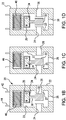
- FIG. 1A shows a front, right-side perspective view of a gas valve or flapper valve 20 that can be used in a valve system in accordance with the present invention and controlled by a method in accordance with the present invention.
- flapper valve 20 includes a housing 22, having an interior 23, an inlet pressure port 24 that is in fluid communication with interior 23 and with the environment outside of housing 22, an inlet vacuum port 26 that is in fluid communication with interior 23 and with the environment outside of housing 22, and an outlet port 28 that is in fluid communication with interior 23 and with the environment outside of housing 22.
- a flapper mechanism 30 that includes a flapper 32, a magnet 34 (shown in FIGS.
- Flapper 32 and flapper stem 36 can be made of the same material, can be continuous with one another, and can be integrally molded together, for example, of one-piece unitary construction.
- the material of flapper 32 can comprise an elastomeric material, for example rubber, and the material also encompasses a magnet 34 to provide a casing 35 surrounding magnet 34.
- flapper 32 can be flexible, resilient, deformable, and elastomeric, it can move together with magnet 34 such that when magnet 34 is made to move flapper 32 moves with it.
- FIG. 1A shows flapper 32 in a first position closing inlet vacuum port 26 while no voltage is applied to solenoid coil 46.
- a spring or other biasing feature can be used to bias flapper 32 in the position shown, in the absence of an applied voltage. In other cases, the relationship between the coil 46, magnet 34, and the biasing feature can be such that flapper 32 would normally be biased in a position to close inlet pressure port 24 instead of inlet vacuum port 26, in the absence of an applied voltage.
- FIG. 1B is a front cross-sectional view of flapper valve 20 shown in FIG. 1A taken along line 50-50 in FIG. 1A .
- flapper 32 is in a first position, seated firmly against an interior rim 27 of inlet vacuum port 26. In this first position flapper 32 forms a leak-free seal between interior 23 and inlet vacuum port 26.
- pressurized gas or air forced into interior 23 through inlet pressure port 24 can pass into interior 23 and exit outlet port 28.
- the pressurized gas or air can be supplied by a source (not shown), for example, a source of clean dry air (CDA).
- a source not shown
- flapper valve 20 can provide a first function when flapper 32 is in this first position.
- FIG. 1C is a front cross-sectional view of flapper valve 20 shown in FIG. 1B but wherein flapper 32 is in a second position seated firmly against an interior rim 25 of inlet pressure port 24.
- Application of an activating voltage to solenoid coil 46 can be used to actuate flapper mechanism 30 and move flapper 32 from the first position shown in FIG. 1B to the second position shown in FIG. 1C .
- flapper 32 forms a leak-free seal between interior 23 and inlet pressure port 24.
- gas or air drawn can be drawn into outlet port 28, through interior 23, and vacuumed out of interior 23 through inlet vacuum port 26.
- a source (not shown) of vacuum or relative negative pressure can be in fluid communication with inlet vacuum port 26.
- flapper valve 20 can provide a second function when flapper 32 is in this second position.
- FIG. ID is a front cross-sectional view of flapper valve 20 shown in FIGS. 1B and 1C but wherein an intermediate voltage is applied to solenoid coil 46 and flapper 32 assumes a neutral position between inlet pressure port 24 and inlet vacuum port 26.
- the intermediate voltage is a voltage that is not as strong as the activating voltage that is applied to solenoid coil 46 to force flapper 32 into the second position shown in FIG. 1C .
- Neither inlet pressure port 24 nor inlet vacuum port 26 is closed when flapper 32 is in the neutral position shown in FIG. ID. With flapper 32 in the neutral position shown, air can flow around flapper 32 from inlet pressure port 24, through interior 23, and out inlet vacuum port 26, to thereby dislodge particles stuck to the flapper.
- flapper 32 By varying the intermediate voltage, for example, by pulse width modulation, by application of alternating current, by varying resistance, or the like, flapper 32 can be made to move toward and away from inlet pressure port 24 and inlet vacuum port 26. The movement toward and away can further assist in dislodging particles stuck to flapper 32.
- FIG. 2 is a side, cross-sectional view of another flapper valve (60) that can be used in a valve system in accordance with the present invention and controlled by a method in accordance with the present invention.
- an intermediate DC voltage can be applied from a DC power supply 90 to a solenoid coil 86 such that a flapper 72 assumes a neutral position between an inlet vacuum port 66 and inlet pressure port 64.
- a controller 94 is used to regulate the amount of DC voltage supplied to solenoid coil 86 to maintain flapper 72 in the neutral position.
- the DC voltage circuit including DC power supply 90 and controller 94, is in electrical communication with terminals 82 and 84 of solenoid coil 86.
- the AC voltage circuit including AC power supply 92 and controller 94, is also in electrical communication with terminals 82 and 84 of solenoid coil 86.
- FIG. 3 is a side view of a magnetic flapper 100 that can be used in a valve system in accordance with the present invention.
- Magnetic flapper 100 comprises an elastomeric flapper 102, a magnet 104, and a casing 106 encompassing magnet 104 and connected to flapper 102.
- Flapper 102 includes a closure disk 108 that is the portion of flapper 102, which makes contact with an inlet pressure port or an inlet vacuum port of a gas valve.
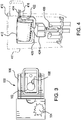
- FIG. 4 is a front, side perspective view of an air valve 410 that incorporates a magnetic flapper 400, for example, a flapper of the type shown in FIG. 3 .
- Air valve 410 can be used in a valve system in accordance with the present invention.
- An outer casing 411 of air valve 410 has been removed so that the positioning of magnetic flapper 400 therein can be seen.
- the coil can be enclosed in a solenoid coil housing 412. Terminals 414 and 416 can be included to connect the solenoid coil to a power source.
- Pole pieces 420 and 422 can be used to extend the magnetic core and can be considered part of the magnetic core.
- Pole pieces 420 and 422 can comprise a material of high magnetic permeability and each can serve to direct the magnetic field produced by the magnetic core and carry the magnetic field from the coil to a permanent magnet 424.
- FIG. 5 is an enlarged view of flapper 102 shown in FIG. 3 and illustrates a foreign particle stuck to closure disk 108 of flapper 102.
- the particle shown is about 100 microns across, at its largest dimension, and even at such a small size is large enough to cause an undesirable leak and set-off an alarm system in a pneumatically-operated dialysis machine.
- the dialysis machine can detect the leak, undergo a self-cleaning operation to try to fix the leak, and if successful, resume operation of the dialysis machine.
- FIG. 6 is a schematic circuit diagram of a microcontroller automated valve driver in accordance with the present invention and which can be used to control a flapper valve to carry out a self-cleaning operation.
- the valve driver can be used in combination with the closed loop system shown in FIG. 7 .
- a pneumatic valve device 110 can be provided with a solenoid coil 112 and a pressure outlet tubing 130 that continues in FIG. 7 .
- Pressure outlet tubing 130 leads to a pressure transducer as described in connection with FIG. 7 .
- FIG. 6 also shows a digital potentiometer 114 configured for controlling a hold current duration. Digital potentiometer 114 can be adjusted to vary the length of time that current is supplied to solenoid coil 112 of pneumatic valve device 110.
- Digital potentiometer 114 includes a decoder 116 configured to receive a serial communication, from a microprocessor, in the form of an ASCII command. Digital potentiometer 114 decodes the serial communication into a resistance value. Digital potentiometer 114 then varies the resistance of its variable resistor based on the decoded serial communication so that current is applied to solenoid coil 112, for an appropriate length of time, to maintain the valve flapper in a neutral position and enable a cleaning operation.
- the strength of the current applied to solenoid coil 112, that is, the controlling peak current value, is controlled by a digital potentiometer 118.
- Digital potentiometer 118 includes a decoder 120 configured similarly to decoder 116.
- Digital potentiometer 118 is configured to vary the current that is applied to pneumatic valve device 110.
- digital potentiometers 114 and 118 can be used, together with an integrated circuit, to control the duration and strength of current applied to solenoid coil 112 of pneumatic valve device 110.
- Digital potentiometers 114 and 118 can be the same as each other, or different from one another.
- Digital potentiometers 114 and 118, and pneumatic valve device 110 are parts of microcontroller automated valve driver circuit that further includes a linear integrated circuit 122 also shown in FIG. 6 .
- Linear integrated circuit 122 is configured in electrical communication with digital potentiometers 114 and 118, and with pneumatic valve device 110.
- Linear integrated circuit 122 can be configured to control a transistor that drives solenoid coil 112.
- An exemplary device that can be used for linear integrated circuit 122 is part number LM1949 available from Texas Instruments of Dallas, Texas.
- the circuit shown in FIG. 6 is configured as a microcontroller automated valve driver that can vary the current peak and current duration applied to pneumatic valve device 110 so that a flapper of the device can be maintained in a neutral position for cleaning.
- the flapper can be made to vibrate so as to clean the flapper of particles trapped on the flapper, or clean particles lodged near or on a pressure port or vacuum port of the corresponding air valve.
- the valve driver shown can supply a DC voltage to solenoid coil 112, which balances the pressure and vacuum forces exerted on the flapper of pneumatic valve device 110. When balanced, the flapper can end up in a neutral position, not closing either an inlet pressure port or an inlet vacuum port.
- one method to determine the appropriate coil DC voltage to achieve such balance is to test the valve in situ.
- testing in situ would entail testing the air valve and circuit after it is installed in the dialysis machine.
- Outlet pressure from the air valve can be measured from an outlet port of the valve and compared to an applied DC voltage.
- the DC voltage that enables the valve flapper to be maintained in the neutral position can then be determined.
- Another method for determining an appropriate DC voltage to be applied to solenoid coil 112 involves the use of a closed loop system built into the dialysis device, which determines an appropriate voltage automatically.
- a closed loop system can use a signal from a pressure sensor on an outlet port of pneumatic valve device 110, as a feedback signal.
- Using a closed loop system can ensure that appropriate voltage is applied to pneumatic valve device 110 even when pneumatic valve device 110 is exposed to temperature, humidity, and altitude changes.
- the closed loop system can respond, based on a signal generated from the pressure sensor, and thus change the voltage applied to solenoid coil 112 to maintain the flapper in the neutral position.
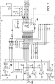
- FIG. 7 shows a schematic diagram of an exemplary closed loop system that can be used for such purpose.
- FIG. 7 is a schematic circuit diagram of a closed loop system according to the present invention, which can be used to automatically determine the appropriate intermediate DC voltage to be applied to the solenoid coil to maintain the flapper in a neutral position.
- the closed loop system also includes the microcontroller automated valve driver shown in FIG. 6 and uses a signal from a pressure sensor on the output port of the pneumatic valve device shown in FIG. 6 , as a feedback signal.
- the circuitry shown in FIG. 7 is in operable communication with the same tubing 130 shown in FIG. 6 , and tubing 130 shown in FIG. 7 is a continuation of tubing 130 shown in FIG. 6 .
- Tubing 130 is connected to an outlet port of pneumatic valve device 110 shown in FIG. 6 , but the closed loop system could be used to control any air valve.
- tubing 130 is also in operable communication with board-mounted pressure sensors 132, 134, and 136.
- Pressure sensor 132 can be a board-mounted pressure transducer configured to measure vacuum drawn on tubing 130, for example, vacuum forces of down to -55.2 kPa (-8 pounds per square inch (PSI)).
- PSI pounds per square inch
- Such vacuum forces are generally provided by pneumatically-operated dialysis machines such as the Liberty® Cycler dialysis machine available from Fresenius Medical Care North America of Waltham Massachusetts, in which the present invention can be implemented.
- An exemplary pressure sensor for such purpose is part number ASDX015D44R available from Honeywell International of Morristown, New Jersey, which can measure pressures of up to 103.4 kPa (15 PSI).
- Tubing 130 can also be an operable communication with pressure sensors 134 and 136, each of which can be configured to measure the maximum pressure generated by the machine in which pneumatic valve device 110 ( FIG. 6 ) is incorporated.
- pressure sensors 134 and 136 should be configured to sense pressures of up to and exceeding 275.8 kPa (40 PSI).
- Such pressures are generally provided by pneumatically-operated dialysis machines such as the Liberty® Cycler dialysis machine available from Fresenius Medical Care North America of Waltham Massachusetts.
- each of pressure sensors 134 and 136 can independently be a board-mounted pressured transducer that can measure up to 689.5 kPa (100 PSI).
- An exemplary pressure transducer exhibiting such capability is part number ASDX100D44R, available from Honeywell International of Morristown, New Jersey.
- Pressure sensors 134 and 136 can be the same as each other, or different from one another.
- the closed loop circuit shown in FIG. 7 also depicts a plurality of integrated circuits (IC), capacitors (C), resistors (R), and test points (TP). These designations are also used in the circuitry shown in FIG. 6 . Moreover, FIG. 7 also shows a plurality of analog-to-digital converters (ADC), and an 8 pin connector (CON8).
- the closed loop circuit shown in FIG. 7 also includes a switched-capacitor, analog-to-digital converter 138 that has a plurality of analog inputs (AIN). The inputs are scaled for normal use with 4.096V reference signals.
- Analog-to-digital converter 138 can be any suitable converter, for example, having 12-bit resolution, 11 channels of analog input, a low power rating, and a sample rate of 200KSPS.
- An exemplary analog-to-digital converter that can be used for this purpose is part number TLV2556, available from Texas Instruments of Dallas, Texas.
- the exemplary circuit shown in FIG. 7 also includes two diode arrays 140 and 142.
- Each of diode arrays 140 and 142 can comprise a quad diode array of transient voltage clamping circuits that are designed to suppress electrostatic-discharge (ESD) and other transient over-voltage events.
- Diode arrays 140 and 142 can be configured to protect input lines to the circuit.
- An exemplary diode array that can be used for such purpose is part number SP724AHT available from LITTELFUSE, Inc. of Chicago, Illinois.
- Diode arrays 140 and 142 can be the same as each other, or different from one another.
- the circuit shown in FIG. 7 also includes a ferrite bead to regulate the current of incoming power and to keep noise off of the 5 volt signal that is supplied to the circuit.
- the ferrite bead is shown in the upper right-hand portion of FIG. 7 .
- the maximum current can be determined in order to hold pneumatic valve device 110 ( FIG. 6 ) in a neutral, half-opened position for a set amount of time to expose particles and the flapper to a flow of air so that the particles can be blown off of the flapper and blown off of other internal valve mechanisms and ports.
- the reaction time of the circuit shown in FIGS. 6 and 7 can be, for example, 200 milliseconds or less, 150 milliseconds or less, 100 milliseconds or less, or 50 milliseconds or less. It is to be understood that the circuitry shown in FIGS. 6 and 7 is exemplary of a circuit for carrying out such high speed monitoring. The circuitry shown is intended to illustrate, not limit, the present invention.
Landscapes
- Engineering & Computer Science (AREA)
- General Engineering & Computer Science (AREA)
- Health & Medical Sciences (AREA)
- Mechanical Engineering (AREA)
- Heart & Thoracic Surgery (AREA)
- Anesthesiology (AREA)
- Pulmonology (AREA)
- Biomedical Technology (AREA)
- Hematology (AREA)
- Life Sciences & Earth Sciences (AREA)
- Animal Behavior & Ethology (AREA)
- General Health & Medical Sciences (AREA)
- Public Health (AREA)
- Veterinary Medicine (AREA)
- Magnetically Actuated Valves (AREA)
Claims (14)
- Ventil-System, das umfasst:eine Magnetspule (46);ein Gasventil, das eine magnetische Ventilklappe umfasst, die an die Magnetspule angrenzt, wobei die magnetische Ventilklappe eine Ventilklappe (32) sowie einen Magneten (34) umfasst und der Magnet durch ein Magnetfeld der Magnetspule bewegt werden kann, das erzeugt wird, wenn eine Spannung an die Magnetspule angelegt wird;eine Stromquelle, die eine Stromversorgung umfasst, wobei die Stromquelle in elektrischer Verbindung mit der Magnetspule steht; undeine Steuerungseinrichtung (94),wobei die Steuerungseinrichtung so eingerichtet ist, dass sie die Stromquelle so steuert, dass1) der Magnetspule von der Stromquelle keine Spannung oder eine erste Spannung zugeführt wird, so dass die magnetische Ventilklappe in einer ersten Position gehalten wird,2) der Magnetspule von der Stromquelle eine zweite Spannung zugeführt wird, so dass die Ventilklappe in einer zweiten Position gehalten wird, und3) der Magnetspule von der Stromquelle eine dritte Spannung zugeführt wird, so dass die Ventilklappe in einer neutralen Position zwischen der ersten Position und der zweiten Position gehalten wird.
- Ventil-System nach Anspruch 1, wobei die Stromquelle so eingerichtet ist, dass sie der Magnetspule Spannung zuführt, die ausreicht, um die Ventilklappe von der ersten Position an die zweite Position zu bewegen, und das Ventil-System so eingerichtet ist, dass die Ventilklappe an die erste Position zurück bewegt wird, wenn die durch die Stromquelle zugeführte Spannung unterbrochen wird.
- Ventil-System nach Anspruch 1, wobei die Stromquelle eine Gleichstrom-Stromversorgung (90) umfasst und die Steuerungseinrichtung so eingerichtet ist, dass sie die Stromquelle so steuert, dass1) der Magnetspule von der Stromquelle keine Spannung oder eine erste Gleichspannung zugeführt wird, so dass die magnetische Ventilklappe in einer ersten Position gehalten wird,2) der Magnetspule von der Stromquelle eine zweite Gleichspannung zugeführt wird, so dass die Ventilklappe in einer zweiten Position gehalten wird, und3) der Magnetspule von der Stromquelle eine dritte Gleichspannung zugeführt wird, so dass die Ventilklappe in einer neutralen Position zwischen der ersten Position und der zweiten Position gehalten wird, und dass sie insbesondere des Weiteren eine integrierte Schaltung umfasst, die eine Wechselstrom-Stromversorgung bildet, wobei die Steuerungseinrichtung so eingerichtet ist, dass der Magnetspule von der Stromquelle eine Gleichspannung zugeführt wird, und der Magnetspule von der Wechselstrom-Stromversorgung gleichzeitig eine Wechselspannung zugeführt wird.
- Ventil-System nach Anspruch 1, wobei die Stromquelle eine Wechselstrom-Stromversorgung (92) umfasst und die Steuerungseinrichtung so eingerichtet ist, dass sie die Stromquelle so steuert, dass1) der Magnetspule von der Stromquelle keine Spannung oder eine erste Wechselspannung zugeführt wird, so dass die magnetische Ventilklappe in einer ersten Position gehalten wird,2) der Magnetspule von der Stromquelle eine zweite Wechselspannung zugeführt wird, so dass die Ventilklappe in einer zweiten Position gehalten wird, und3) der Magnetspule von der Stromquelle eine dritte Wechselspannung zugeführt wird, so dass die Ventilklappe in einer neutralen Position zwischen der ersten Position und der zweiten Position gehalten wird.
- Ventil-System nach Anspruch 1, das des Weiteren ein Gehäuse (22) umfasst, wobei die magnetische Ventilklappe im Inneren des Gehäuses angeordnet ist, dass Gehäuse einen Einlass-Druckanschluss (24), einen Einlass-Sauganschluss (26) sowie einen Auslass-Anschluss (28) umfasst, die Ventilklappe so eingerichtet ist, dass der Einlass-Druckanschluss geschlossen ist, wenn sich die Ventilklappe in einer ersten Position befindet, die Ventilklappe so eingerichtet ist, dass der Einlass-Sauganschluss geschlossen ist, wenn sich die Ventilklappe in einer zweiten Position befindet, und die Stromquellen so eingerichtet sind, dass sie der Magnetspule Spannung bereitstellen, die ausreicht, um entweder die Ventilklappe von der ersten Position an die zweite Position zu bewegen oder die Ventilklappe von der zweiten Position an die erste Position zu bewegen.
- Ventil-System nach Anspruch 5, das des Weiteren umfasst:einen Drucksensor, der in funktionaler Verbindung mit dem Auslass-Anschluss steht und so eingerichtet ist, dass er den Druck von Fluid erfasst, das über den Auslass-Anschluss Austritt oder eintritt; undeine Schaltung, die so eingerichtet ist, dass sie ein Rückkopplungs-Signal, das durch den Drucksensor erfassten Druck anzeigt, zu der Steuerungseinrichtung leitet,wobei die Steuerungseinrichtung so eingerichtet ist, dass sie die Stromquelle so steuert, dass die dritte Spannung erhöht, gesenkt oder aufrechterhalten wird, so dass auf Basis des Kopplungs-Signals der Druck von Fluid, das über den Auslass-Anschluss austritt oder eintritt, innerhalb eines zulässigen Bereiches von Drücken gehalten wird, wobei der zulässige Bereich von drückenden insbesondere ein Bereich von Drücken ist, der anzeigt, dass die Ventilklappe in einer neutralen Position zwischen der ersten Position und der zweiten Position gehalten wird.
- Ventil-System nach Anspruch 3, wobei die dritte Gleichspannung eine durchschnittliche Spannung umfasst, die höher ist als die erste Gleichspannung und/oder höher als 0, und niedriger als die zweite Gleichspannung, wobei die erste Gleichspannung insbesondere 0 beträgt.
- Ventil-System nach Anspruch 1, das des Weiteren eine zweite Stromquelle umfasst, die so eingerichtet ist, dass sie Wechselspannung zuführt, wobei die Steuerungseinrichtung so eingerichtet ist, dass sie gleichzeitig:1) der Magnetspule von der ersten Stromquelle die dritte Gleichspannung zuführt;2) der Magnetspule von der zweiten Stromquelle Wechselspannung zuführt; und3) Oszillation der Wechselspannung so steuert, dass die Ventilklappe in Schwingung versetzt wird, während sie sich in der neutralen Position zwischen der ersten Position und der zweiten Position befindet, ohne dass sie an der ersten Position oder der zweiten Position anschlägt.
- Ventil-System nach Anspruch 1, wobei die Stromquelle eine Gleichstrom-Stromversorgung (90) umfasst und die Steuerungseinrichtung so eingerichtet ist, dass sie die Stromquelle so steuert, dass1) der Magnetspule von der Stromquelle keine Spannung oder eine erste Gleichspannung zugeführt wird, so dass die magnetische Ventilklappe in einer ersten Position gehalten wird,2) der Magnetspule von der Stromquelle eine zweite Gleichspannung zugeführt wird, so dass die Ventilklappe in einer zweiten Position gehalten wird, und3) der Magnetspule von der Stromquelle eine dritte Gleichspannung zugeführt wird, so dass die Ventilklappe in einer neutralen Position zwischen der ersten Position und der zweiten Position gehalten wird.
- Kombination aus dem Ventil-System nach Anspruch 1 und einer pneumatisch betriebenen Dialysemaschine, wobei die pneumatisch betriebene Dialysemaschine eine DruckfluidQuelle, die in Fluidverbindung mit dem Einlass-Druckanschluss besteht, und eine VakuumQuelle umfasst, die in Fluidverbindung mit dem Einlass-Sauganschluss steht.
- Verfahren zum Reinigen der magnetischen Ventilklappe nach Anspruch 1 in einem Gasventil in einem pneumatischen System, wobei das Verfahren umfasst:Anlegen einer ersten aktivierenden Spannung an die Magnetspule, wobei die erste aktivierende Spannung ausreichend stark ist, um die Magnetspule zu aktivieren und die magnetische Ventilklappe von der ersten Position, an der die magnetische Ventilklappe einen ersten pneumatischen Anschluss schließt, an die neutrale Position zu bewegen, an der die magnetische Ventilklappe zwischen dem ersten pneumatischen Anschluss und einem zweiten, anderen pneumatischen Anschluss gehalten wird, wobei die Magnetspule so eingerichtet ist, dass beim Anlegen einer zweiten Spannung, die höher ist als die erste aktivierende Spannung, die Magnetische Ventilklappe an die zweite Position bewegt wird, an der sie den zweiten pneumatischen Anschluss schließt;Halten der ersten aktivierenden Spannung, um die magnetische Ventilklappe in der neutralen Position zwischen dem ersten pneumatischen Anschluss und dem zweiten pneumatischen Anschluss zu halten; sowieLeiten eines Gases um die magnetische Ventilklappe herum von dem zweiten pneumatischen Anschluss zu dem ersten pneumatischen Anschluss, während die magnetische Ventilklappe in der neutralen Position gehalten wird, um so die magnetische Ventilklappe zu reinigen.
- Verfahren nach Anspruch 11, das des Weiteren umfasst, dass eine Wechselspannung an die Magnetspule angelegt wird, während die magnetische Ventilklappe in der neutralen Position gehalten wird, um die magnetische Ventilklappe in Schwingung zu versetzen, und das des Weiteren umfasst, dass ein Schalter aktiviert wird, um eine Quelle der Wechselspannung zu trennen und den Reinigungs-Modus zu beenden.
- Verfahren nach Anspruch 12, das des Weiteren umfasst:Erfassen des Drucks von Gas, das über einen Anschluss in das/aus dem Gasventil eintritt oder austritt; und
Senden eines Signals, das den erfassten Druck anzeigt, zu einer Steuerungseinrichtung,wobei das Halten der ersten aktivierenden Spannung umfasst, dass die Steuerungseinrichtung eingesetzt wird, um die erste aktivierende Spannung auf Basis des Signals so anzupassen, dass die magnetische Ventilklappe in der neutralen Position zwischen dem ersten pneumatischen Anschluss und dem zweiten pneumatischen Anschluss gehalten wird, und/oder es des Weiteren umfasst:Erfassen eines Gasaustritts in dem Gasventil vor Anlegen einer ersten aktivierenden Spannung;Anlegen der ersten aktivierenden Spannung in Reaktion auf Erfassen des Gasaustritts; undPrüfen auf einen Gasaustritt in dem Gasventil nach Leiten des Gases um die magnetische Ventilklappe herum zum Reinigen der magnetischen Ventilklappe. - Verfahren nach Anspruch 11, das des Weiteren umfasst:
Erfassen des Drucks von Gas, das über einen Anschluss in das/aus dem Gasventil eintritt oder austritt;Senden eines Signals, das den erfassten Druck anzeigt, zu einer Steuerungseinrichtung;Erfassen eines Gasaustritts in dem Gasventil vor Anlegen einer ersten aktivierenden Spannung;Anlegen der ersten aktivierenden Spannung in Reaktion auf Erfassen des Gasaustritts; undPrüfen auf einen Gasaustritt in dem Gasventil nach Leiten des Gases um die magnetische Ventilklappe herum zum Reinigen der magnetischen Ventilklappe.
Applications Claiming Priority (2)
| Application Number | Priority Date | Filing Date | Title |
|---|---|---|---|
| US13/838,701 US9044586B2 (en) | 2013-03-15 | 2013-03-15 | Dialysis control valve having self-cleaning mode |
| PCT/US2014/017300 WO2014149334A1 (en) | 2013-03-15 | 2014-02-20 | Dialysis control valve having self-cleaning mode |
Publications (2)
| Publication Number | Publication Date |
|---|---|
| EP2968897A1 EP2968897A1 (de) | 2016-01-20 |
| EP2968897B1 true EP2968897B1 (de) | 2019-04-03 |
Family
ID=50241536
Family Applications (1)
| Application Number | Title | Priority Date | Filing Date |
|---|---|---|---|
| EP14709476.7A Active EP2968897B1 (de) | 2013-03-15 | 2014-02-20 | Dialysesteuerventil mit selbstreinigungsmodus |
Country Status (4)
| Country | Link |
|---|---|
| US (1) | US9044586B2 (de) |
| EP (1) | EP2968897B1 (de) |
| CN (1) | CN105142713B (de) |
| WO (1) | WO2014149334A1 (de) |
Families Citing this family (16)
| Publication number | Priority date | Publication date | Assignee | Title |
|---|---|---|---|---|
| US20150201842A1 (en) * | 2014-01-21 | 2015-07-23 | Olympus Medical Systems Corp. | Measurement probe and optical measurement system |
| WO2016057981A1 (en) | 2014-10-10 | 2016-04-14 | Nxstage Medical, Inc. | Pinch clamp devices, methods, and systems |
| EP3047873A1 (de) * | 2015-01-22 | 2016-07-27 | ECP Entwicklungsgesellschaft mbH | Magnetisch betätigbares ventil zur steuerung des fluidflusses durch einen katheter |
| KR20250159266A (ko) * | 2015-01-22 | 2025-11-10 | 이씨피 엔트빅클룽스게젤샤프트 엠베하 | 유체내의 자성입자를 보유하기 위한 분리장치와 기능성 부재를 위한 보호장치를 포함하는 카테터장치 |
| WO2016148687A1 (en) * | 2015-03-16 | 2016-09-22 | Halliburton Energy Services, Inc. | Downhole fluid flow direction sensor |
| US9684310B2 (en) * | 2015-07-17 | 2017-06-20 | Automatic Switch Company | Compensated performance of a solenoid valve based on environmental conditions and product life |
| AT517969B1 (de) * | 2015-11-26 | 2017-10-15 | Roland Aschauer Dr | Dampfdruckmessgerät |
| GB201801704D0 (en) * | 2018-02-02 | 2018-03-21 | Rolls Royce Plc | Fuel flow valve |
| EP3597937B1 (de) * | 2018-07-20 | 2022-12-28 | Hamilton Sundstrand Corporation | Servoventil |
| CN109481982A (zh) * | 2018-10-18 | 2019-03-19 | 海宁市英德赛电子有限公司 | 一种6n4高纯氨的精馏制备设备及工艺 |
| US11466791B2 (en) * | 2020-04-10 | 2022-10-11 | The Boeing Company | Bistable hydraulic solenoid valve |
| CN112197054B (zh) * | 2020-09-28 | 2022-07-05 | 东风商用车有限公司 | 一种带位置反馈的阀门自清洁控制方法 |
| EP4304501A4 (de) * | 2021-03-08 | 2025-04-16 | CONMED Corporation | Solenoide für insufflationssysteme |
| EP4102241A1 (de) * | 2021-06-10 | 2022-12-14 | Koninklijke Philips N.V. | Lösen eines beweglichen teils in einer schaltbaren vorrichtung eines mrt-systems |
| US12019807B2 (en) * | 2021-11-01 | 2024-06-25 | Meta Platforms Technologies, Llc | Soft stretchable high-density fluidic routing using multi-channel tubing, connectors, and breakout |
| WO2023096898A1 (en) | 2021-11-24 | 2023-06-01 | Silk Road Medical, Inc. | Stopcock with indexing mechanism providing feedback of hub position |
Family Cites Families (22)
| Publication number | Priority date | Publication date | Assignee | Title |
|---|---|---|---|---|
| US3215162A (en) * | 1962-04-20 | 1965-11-02 | Ford Motor Co | Bistable control valve |
| US3379214A (en) * | 1965-01-15 | 1968-04-23 | Skinner Prec Ind Inc | Permanent magnet valve assembly |
| US3570807A (en) * | 1969-01-14 | 1971-03-16 | Bell Aerospace Corp | Electromechanical control valve |
| US3598360A (en) * | 1969-08-27 | 1971-08-10 | Richdel | Solenoid valve |
| US3919923A (en) * | 1972-03-18 | 1975-11-18 | Lucas Aerospace Ltd | Fluid flow control valve |
| US4081171A (en) | 1976-06-07 | 1978-03-28 | Clemar Manufacturing Corporation | Self-cleaning filter assembly for solenoid-actuated valves |
| US4252651A (en) | 1979-08-29 | 1981-02-24 | Baxter Travenol Laboratories, Inc. | Negative pressure valving system and transmembrane pressure alarm system |
| US4627461A (en) | 1985-10-03 | 1986-12-09 | K. J. Baillie Pty. Ltd. | Self cleaning valve |
| JP2990844B2 (ja) * | 1991-04-30 | 1999-12-13 | 株式会社デンソー | 三方電磁弁 |
| US5113892A (en) | 1991-08-19 | 1992-05-19 | Hull Harold L | Freeze control and drain valve |
| IL120860A0 (en) | 1997-05-19 | 1997-09-30 | Q Core Ltd | Fluid flow control system |
| DE59811319D1 (de) * | 1997-06-09 | 2004-06-09 | Buerkert Werke Gmbh & Co | Miniaturisiertes magnetventil |
| JP3466061B2 (ja) | 1997-09-02 | 2003-11-10 | 本田技研工業株式会社 | 車両用自動変速機の制御装置 |
| US6195834B1 (en) | 1999-03-25 | 2001-03-06 | David Shteingold | Method and apparatus for removing foreign particles |
| US6966325B2 (en) | 2002-09-20 | 2005-11-22 | Advanced Neuromodulation Systems, Inc. | Method for manipulating dosage control apparatus |
| US7935074B2 (en) | 2005-02-28 | 2011-05-03 | Fresenius Medical Care Holdings, Inc. | Cassette system for peritoneal dialysis machine |
| US8240636B2 (en) * | 2009-01-12 | 2012-08-14 | Fresenius Medical Care Holdings, Inc. | Valve system |
| US7746620B2 (en) | 2008-02-22 | 2010-06-29 | Baxter International Inc. | Medical fluid machine having solenoid control system with temperature compensation |
| US7782590B2 (en) | 2008-02-22 | 2010-08-24 | Baxter International Inc. | Medical fluid machine having solenoid control system with reduced hold current |
| US8609293B2 (en) * | 2010-10-01 | 2013-12-17 | GM Global Technology Operations LLC | High pressure tank valve sealing by using the elastic properties of O-rings |
| DE102011105916B4 (de) | 2011-06-29 | 2013-03-28 | Fresenius Medical Care Deutschland Gmbh | Dialysemaschine |
| US20130144223A1 (en) | 2011-07-25 | 2013-06-06 | Nicholas D. Hewitt | Neural drug delivery system with microvalves |
-
2013
- 2013-03-15 US US13/838,701 patent/US9044586B2/en not_active Expired - Fee Related
-
2014
- 2014-02-20 WO PCT/US2014/017300 patent/WO2014149334A1/en not_active Ceased
- 2014-02-20 EP EP14709476.7A patent/EP2968897B1/de active Active
- 2014-02-20 CN CN201480016217.XA patent/CN105142713B/zh not_active Expired - Fee Related
Non-Patent Citations (1)
| Title |
|---|
| None * |
Also Published As
| Publication number | Publication date |
|---|---|
| US20140261717A1 (en) | 2014-09-18 |
| CN105142713A (zh) | 2015-12-09 |
| WO2014149334A1 (en) | 2014-09-25 |
| EP2968897A1 (de) | 2016-01-20 |
| US9044586B2 (en) | 2015-06-02 |
| CN105142713B (zh) | 2018-01-30 |
Similar Documents
| Publication | Publication Date | Title |
|---|---|---|
| EP2968897B1 (de) | Dialysesteuerventil mit selbstreinigungsmodus | |
| CN101484060B (zh) | 带有过滤器自清洁装置的吸尘器 | |
| US8468884B2 (en) | Motor controlled speed pipeline apparatus and method | |
| US6648012B2 (en) | Non-return valve override device | |
| JP3502597B2 (ja) | 二方弁 | |
| US10143786B2 (en) | Breast pump system | |
| KR100376127B1 (ko) | 흡인 밸브 | |
| KR20160056873A (ko) | 전자 장치로의 전력을 제어하는 방법 및 장치 | |
| CN101233322B (zh) | 具有带电池和螺线管电子监控的电子监控的空气阀的往复泵 | |
| CN101233321B (zh) | 具有电子监控的空气阀和活塞的往复泵 | |
| CN110312538A (zh) | 夹紧软管管路的设备和具有夹紧软管管路的设备的医学治疗设备和监控夹紧软管管路的设备的方法 | |
| CN103055401A (zh) | 呼吸机及比例阀 | |
| CN111692138B (zh) | 集成式真空发生器及使用方法 | |
| JP2007508013A (ja) | フィルタースナッパー | |
| JP2005511923A5 (de) | ||
| US11131398B2 (en) | Smart pinch valve | |
| CN212672542U (zh) | 一种夹管阀工作状态检测装置 | |
| US11221078B2 (en) | Pinch valve guard | |
| JP3527346B2 (ja) | ガスメータ用遮断弁制御装置 | |
| Kluge et al. | Pneumatic silicon microvalves with piezoelectric actuation | |
| CN112461730B (zh) | 一种空气过滤器状态监测装置 | |
| CN214201097U (zh) | 一种空气过滤器状态监测装置 | |
| JP2000074254A (ja) | 純水・薬液供給用空気圧シリンダ操作弁の制御装置及び制御方法 | |
| JP6889891B1 (ja) | 漏れ検知機能付き弁および漏れ検知装置 | |
| JPH0569998A (ja) | 真空供給用ユニツト |
Legal Events
| Date | Code | Title | Description |
|---|---|---|---|
| PUAI | Public reference made under article 153(3) epc to a published international application that has entered the european phase |
Free format text: ORIGINAL CODE: 0009012 |
|
| 17P | Request for examination filed |
Effective date: 20151014 |
|
| AK | Designated contracting states |
Kind code of ref document: A1 Designated state(s): AL AT BE BG CH CY CZ DE DK EE ES FI FR GB GR HR HU IE IS IT LI LT LU LV MC MK MT NL NO PL PT RO RS SE SI SK SM TR |
|
| AX | Request for extension of the european patent |
Extension state: BA ME |
|
| RIN1 | Information on inventor provided before grant (corrected) |
Inventor name: JAMES, PHILIP, SCOTT Inventor name: EGLEY, BERT, D. |
|
| DAX | Request for extension of the european patent (deleted) | ||
| GRAP | Despatch of communication of intention to grant a patent |
Free format text: ORIGINAL CODE: EPIDOSNIGR1 |
|
| STAA | Information on the status of an ep patent application or granted ep patent |
Free format text: STATUS: GRANT OF PATENT IS INTENDED |
|
| INTG | Intention to grant announced |
Effective date: 20181004 |
|
| GRAS | Grant fee paid |
Free format text: ORIGINAL CODE: EPIDOSNIGR3 |
|
| GRAA | (expected) grant |
Free format text: ORIGINAL CODE: 0009210 |
|
| STAA | Information on the status of an ep patent application or granted ep patent |
Free format text: STATUS: THE PATENT HAS BEEN GRANTED |
|
| AK | Designated contracting states |
Kind code of ref document: B1 Designated state(s): AL AT BE BG CH CY CZ DE DK EE ES FI FR GB GR HR HU IE IS IT LI LT LU LV MC MK MT NL NO PL PT RO RS SE SI SK SM TR |
|
| REG | Reference to a national code |
Ref country code: GB Ref legal event code: FG4D |
|
| REG | Reference to a national code |
Ref country code: CH Ref legal event code: EP Ref country code: AT Ref legal event code: REF Ref document number: 1114986 Country of ref document: AT Kind code of ref document: T Effective date: 20190415 |
|
| REG | Reference to a national code |
Ref country code: DE Ref legal event code: R096 Ref document number: 602014043970 Country of ref document: DE |
|
| REG | Reference to a national code |
Ref country code: IE Ref legal event code: FG4D |
|
| REG | Reference to a national code |
Ref country code: SE Ref legal event code: TRGR |
|
| REG | Reference to a national code |
Ref country code: NL Ref legal event code: MP Effective date: 20190403 |
|
| REG | Reference to a national code |
Ref country code: LT Ref legal event code: MG4D |
|
| REG | Reference to a national code |
Ref country code: AT Ref legal event code: MK05 Ref document number: 1114986 Country of ref document: AT Kind code of ref document: T Effective date: 20190403 |
|
| PG25 | Lapsed in a contracting state [announced via postgrant information from national office to epo] |
Ref country code: NL Free format text: LAPSE BECAUSE OF FAILURE TO SUBMIT A TRANSLATION OF THE DESCRIPTION OR TO PAY THE FEE WITHIN THE PRESCRIBED TIME-LIMIT Effective date: 20190403 |
|
| PG25 | Lapsed in a contracting state [announced via postgrant information from national office to epo] |
Ref country code: LT Free format text: LAPSE BECAUSE OF FAILURE TO SUBMIT A TRANSLATION OF THE DESCRIPTION OR TO PAY THE FEE WITHIN THE PRESCRIBED TIME-LIMIT Effective date: 20190403 Ref country code: FI Free format text: LAPSE BECAUSE OF FAILURE TO SUBMIT A TRANSLATION OF THE DESCRIPTION OR TO PAY THE FEE WITHIN THE PRESCRIBED TIME-LIMIT Effective date: 20190403 Ref country code: PT Free format text: LAPSE BECAUSE OF FAILURE TO SUBMIT A TRANSLATION OF THE DESCRIPTION OR TO PAY THE FEE WITHIN THE PRESCRIBED TIME-LIMIT Effective date: 20190803 Ref country code: NO Free format text: LAPSE BECAUSE OF FAILURE TO SUBMIT A TRANSLATION OF THE DESCRIPTION OR TO PAY THE FEE WITHIN THE PRESCRIBED TIME-LIMIT Effective date: 20190703 Ref country code: HR Free format text: LAPSE BECAUSE OF FAILURE TO SUBMIT A TRANSLATION OF THE DESCRIPTION OR TO PAY THE FEE WITHIN THE PRESCRIBED TIME-LIMIT Effective date: 20190403 Ref country code: AL Free format text: LAPSE BECAUSE OF FAILURE TO SUBMIT A TRANSLATION OF THE DESCRIPTION OR TO PAY THE FEE WITHIN THE PRESCRIBED TIME-LIMIT Effective date: 20190403 Ref country code: CZ Free format text: LAPSE BECAUSE OF FAILURE TO SUBMIT A TRANSLATION OF THE DESCRIPTION OR TO PAY THE FEE WITHIN THE PRESCRIBED TIME-LIMIT Effective date: 20190403 Ref country code: ES Free format text: LAPSE BECAUSE OF FAILURE TO SUBMIT A TRANSLATION OF THE DESCRIPTION OR TO PAY THE FEE WITHIN THE PRESCRIBED TIME-LIMIT Effective date: 20190403 |
|
| PG25 | Lapsed in a contracting state [announced via postgrant information from national office to epo] |
Ref country code: GR Free format text: LAPSE BECAUSE OF FAILURE TO SUBMIT A TRANSLATION OF THE DESCRIPTION OR TO PAY THE FEE WITHIN THE PRESCRIBED TIME-LIMIT Effective date: 20190704 Ref country code: RS Free format text: LAPSE BECAUSE OF FAILURE TO SUBMIT A TRANSLATION OF THE DESCRIPTION OR TO PAY THE FEE WITHIN THE PRESCRIBED TIME-LIMIT Effective date: 20190403 Ref country code: BG Free format text: LAPSE BECAUSE OF FAILURE TO SUBMIT A TRANSLATION OF THE DESCRIPTION OR TO PAY THE FEE WITHIN THE PRESCRIBED TIME-LIMIT Effective date: 20190703 Ref country code: LV Free format text: LAPSE BECAUSE OF FAILURE TO SUBMIT A TRANSLATION OF THE DESCRIPTION OR TO PAY THE FEE WITHIN THE PRESCRIBED TIME-LIMIT Effective date: 20190403 Ref country code: PL Free format text: LAPSE BECAUSE OF FAILURE TO SUBMIT A TRANSLATION OF THE DESCRIPTION OR TO PAY THE FEE WITHIN THE PRESCRIBED TIME-LIMIT Effective date: 20190403 |
|
| PG25 | Lapsed in a contracting state [announced via postgrant information from national office to epo] |
Ref country code: AT Free format text: LAPSE BECAUSE OF FAILURE TO SUBMIT A TRANSLATION OF THE DESCRIPTION OR TO PAY THE FEE WITHIN THE PRESCRIBED TIME-LIMIT Effective date: 20190403 Ref country code: IS Free format text: LAPSE BECAUSE OF FAILURE TO SUBMIT A TRANSLATION OF THE DESCRIPTION OR TO PAY THE FEE WITHIN THE PRESCRIBED TIME-LIMIT Effective date: 20190803 |
|
| REG | Reference to a national code |
Ref country code: DE Ref legal event code: R097 Ref document number: 602014043970 Country of ref document: DE |
|
| PG25 | Lapsed in a contracting state [announced via postgrant information from national office to epo] |
Ref country code: EE Free format text: LAPSE BECAUSE OF FAILURE TO SUBMIT A TRANSLATION OF THE DESCRIPTION OR TO PAY THE FEE WITHIN THE PRESCRIBED TIME-LIMIT Effective date: 20190403 Ref country code: DK Free format text: LAPSE BECAUSE OF FAILURE TO SUBMIT A TRANSLATION OF THE DESCRIPTION OR TO PAY THE FEE WITHIN THE PRESCRIBED TIME-LIMIT Effective date: 20190403 Ref country code: SK Free format text: LAPSE BECAUSE OF FAILURE TO SUBMIT A TRANSLATION OF THE DESCRIPTION OR TO PAY THE FEE WITHIN THE PRESCRIBED TIME-LIMIT Effective date: 20190403 Ref country code: RO Free format text: LAPSE BECAUSE OF FAILURE TO SUBMIT A TRANSLATION OF THE DESCRIPTION OR TO PAY THE FEE WITHIN THE PRESCRIBED TIME-LIMIT Effective date: 20190403 |
|
| PLBE | No opposition filed within time limit |
Free format text: ORIGINAL CODE: 0009261 |
|
| STAA | Information on the status of an ep patent application or granted ep patent |
Free format text: STATUS: NO OPPOSITION FILED WITHIN TIME LIMIT |
|
| PG25 | Lapsed in a contracting state [announced via postgrant information from national office to epo] |
Ref country code: SM Free format text: LAPSE BECAUSE OF FAILURE TO SUBMIT A TRANSLATION OF THE DESCRIPTION OR TO PAY THE FEE WITHIN THE PRESCRIBED TIME-LIMIT Effective date: 20190403 |
|
| 26N | No opposition filed |
Effective date: 20200106 |
|
| PG25 | Lapsed in a contracting state [announced via postgrant information from national office to epo] |
Ref country code: TR Free format text: LAPSE BECAUSE OF FAILURE TO SUBMIT A TRANSLATION OF THE DESCRIPTION OR TO PAY THE FEE WITHIN THE PRESCRIBED TIME-LIMIT Effective date: 20190403 |
|
| PG25 | Lapsed in a contracting state [announced via postgrant information from national office to epo] |
Ref country code: SI Free format text: LAPSE BECAUSE OF FAILURE TO SUBMIT A TRANSLATION OF THE DESCRIPTION OR TO PAY THE FEE WITHIN THE PRESCRIBED TIME-LIMIT Effective date: 20190403 |
|
| REG | Reference to a national code |
Ref country code: CH Ref legal event code: PL |
|
| REG | Reference to a national code |
Ref country code: BE Ref legal event code: MM Effective date: 20200229 |
|
| PG25 | Lapsed in a contracting state [announced via postgrant information from national office to epo] |
Ref country code: MC Free format text: LAPSE BECAUSE OF FAILURE TO SUBMIT A TRANSLATION OF THE DESCRIPTION OR TO PAY THE FEE WITHIN THE PRESCRIBED TIME-LIMIT Effective date: 20190403 Ref country code: LU Free format text: LAPSE BECAUSE OF NON-PAYMENT OF DUE FEES Effective date: 20200220 |
|
| PG25 | Lapsed in a contracting state [announced via postgrant information from national office to epo] |
Ref country code: CH Free format text: LAPSE BECAUSE OF NON-PAYMENT OF DUE FEES Effective date: 20200229 Ref country code: LI Free format text: LAPSE BECAUSE OF NON-PAYMENT OF DUE FEES Effective date: 20200229 |
|
| PG25 | Lapsed in a contracting state [announced via postgrant information from national office to epo] |
Ref country code: IE Free format text: LAPSE BECAUSE OF NON-PAYMENT OF DUE FEES Effective date: 20200220 |
|
| PG25 | Lapsed in a contracting state [announced via postgrant information from national office to epo] |
Ref country code: BE Free format text: LAPSE BECAUSE OF NON-PAYMENT OF DUE FEES Effective date: 20200229 |
|
| PG25 | Lapsed in a contracting state [announced via postgrant information from national office to epo] |
Ref country code: MT Free format text: LAPSE BECAUSE OF FAILURE TO SUBMIT A TRANSLATION OF THE DESCRIPTION OR TO PAY THE FEE WITHIN THE PRESCRIBED TIME-LIMIT Effective date: 20190403 Ref country code: CY Free format text: LAPSE BECAUSE OF FAILURE TO SUBMIT A TRANSLATION OF THE DESCRIPTION OR TO PAY THE FEE WITHIN THE PRESCRIBED TIME-LIMIT Effective date: 20190403 |
|
| PG25 | Lapsed in a contracting state [announced via postgrant information from national office to epo] |
Ref country code: MK Free format text: LAPSE BECAUSE OF FAILURE TO SUBMIT A TRANSLATION OF THE DESCRIPTION OR TO PAY THE FEE WITHIN THE PRESCRIBED TIME-LIMIT Effective date: 20190403 |
|
| PGFP | Annual fee paid to national office [announced via postgrant information from national office to epo] |
Ref country code: FR Payment date: 20230119 Year of fee payment: 10 |
|
| PGFP | Annual fee paid to national office [announced via postgrant information from national office to epo] |
Ref country code: SE Payment date: 20230119 Year of fee payment: 10 Ref country code: IT Payment date: 20230120 Year of fee payment: 10 Ref country code: GB Payment date: 20230120 Year of fee payment: 10 Ref country code: DE Payment date: 20230119 Year of fee payment: 10 |
|
| P01 | Opt-out of the competence of the unified patent court (upc) registered |
Effective date: 20230602 |
|
| REG | Reference to a national code |
Ref country code: DE Ref legal event code: R119 Ref document number: 602014043970 Country of ref document: DE |
|
| REG | Reference to a national code |
Ref country code: SE Ref legal event code: EUG |
|
| GBPC | Gb: european patent ceased through non-payment of renewal fee |
Effective date: 20240220 |
|
| PG25 | Lapsed in a contracting state [announced via postgrant information from national office to epo] |
Ref country code: DE Free format text: LAPSE BECAUSE OF NON-PAYMENT OF DUE FEES Effective date: 20240903 |
|
| PG25 | Lapsed in a contracting state [announced via postgrant information from national office to epo] |
Ref country code: GB Free format text: LAPSE BECAUSE OF NON-PAYMENT OF DUE FEES Effective date: 20240220 |
|
| PG25 | Lapsed in a contracting state [announced via postgrant information from national office to epo] |
Ref country code: FR Free format text: LAPSE BECAUSE OF NON-PAYMENT OF DUE FEES Effective date: 20240229 |
|
| PG25 | Lapsed in a contracting state [announced via postgrant information from national office to epo] |
Ref country code: GB Free format text: LAPSE BECAUSE OF NON-PAYMENT OF DUE FEES Effective date: 20240220 Ref country code: FR Free format text: LAPSE BECAUSE OF NON-PAYMENT OF DUE FEES Effective date: 20240229 Ref country code: DE Free format text: LAPSE BECAUSE OF NON-PAYMENT OF DUE FEES Effective date: 20240903 |
|
| PG25 | Lapsed in a contracting state [announced via postgrant information from national office to epo] |
Ref country code: IT Free format text: LAPSE BECAUSE OF NON-PAYMENT OF DUE FEES Effective date: 20240220 |
|
| PG25 | Lapsed in a contracting state [announced via postgrant information from national office to epo] |
Ref country code: SE Free format text: LAPSE BECAUSE OF NON-PAYMENT OF DUE FEES Effective date: 20240221 |