EP2969265B1 - Tamis vibratoire en polyuréthane - Google Patents
Tamis vibratoire en polyuréthane Download PDFInfo
- Publication number
- EP2969265B1 EP2969265B1 EP14711661.0A EP14711661A EP2969265B1 EP 2969265 B1 EP2969265 B1 EP 2969265B1 EP 14711661 A EP14711661 A EP 14711661A EP 2969265 B1 EP2969265 B1 EP 2969265B1
- Authority
- EP
- European Patent Office
- Prior art keywords
- members
- edge portion
- reinforcement
- screen
- vibratory screen
- Prior art date
- Legal status (The legal status is an assumption and is not a legal conclusion. Google has not performed a legal analysis and makes no representation as to the accuracy of the status listed.)
- Active
Links
Images


Classifications
-
- B—PERFORMING OPERATIONS; TRANSPORTING
- B07—SEPARATING SOLIDS FROM SOLIDS; SORTING
- B07B—SEPARATING SOLIDS FROM SOLIDS BY SIEVING, SCREENING, SIFTING OR BY USING GAS CURRENTS; SEPARATING BY OTHER DRY METHODS APPLICABLE TO BULK MATERIAL, e.g. LOOSE ARTICLES FIT TO BE HANDLED LIKE BULK MATERIAL
- B07B1/00—Sieving, screening, sifting, or sorting solid materials using networks, gratings, grids, or the like
- B07B1/46—Constructional details of screens in general; Cleaning or heating of screens
- B07B1/4609—Constructional details of screens in general; Cleaning or heating of screens constructional details of screening surfaces or meshes
- B07B1/4681—Meshes of intersecting, non-woven, elements
-
- B—PERFORMING OPERATIONS; TRANSPORTING
- B07—SEPARATING SOLIDS FROM SOLIDS; SORTING
- B07B—SEPARATING SOLIDS FROM SOLIDS BY SIEVING, SCREENING, SIFTING OR BY USING GAS CURRENTS; SEPARATING BY OTHER DRY METHODS APPLICABLE TO BULK MATERIAL, e.g. LOOSE ARTICLES FIT TO BE HANDLED LIKE BULK MATERIAL
- B07B1/00—Sieving, screening, sifting, or sorting solid materials using networks, gratings, grids, or the like
- B07B1/46—Constructional details of screens in general; Cleaning or heating of screens
- B07B1/4609—Constructional details of screens in general; Cleaning or heating of screens constructional details of screening surfaces or meshes
- B07B1/4663—Multi-layer screening surfaces
Definitions
- the present invention relates to an improved molded polyurethane screen.
- Molded polyurethane screens having reinforcement therein are known in the art.
- the dividing strips between the openings were relatively large, thereby causing the open area of the screen to be an undesirably low percentage of its surface, thereby in turn causing the screen to be relatively inefficient.
- the present invention is an improvement over U.S. Patent Nos. 4,819,809 and 4,857,176 .
- the present invention provides improved screens with relatively high percentage open screening areas and high efficiencies.
- US2004/211707 relates to an undulating molded plastic vibratory screen for a vibratory screening machine, and discloses a vibratory screen as per the preamble of claim 1.
- US4857176 relates to a molded polyurethane screen.
- a vibratory screen as set out in claim 1 and a method of making a vibratory screen as set out in claim 12.
- Example embodiments of the present invention are described in more detail below with reference to the appended Figures.
- a vibratory screen 10 includes a body 12 of molded polyurethane having unperforated side edge portions 14, 16.
- Side edge portions 14, 16 may each have an upward U-shape and may each include a cast-in structural member, such as angle 15 shown in FIG. 2 .
- Side edge portions 14, 16 may also be formed without cast-in structural members and/or may include other structural members.
- Side edge portions 14, 16 may be formed in a U-shape or any other suitable shape for attachment to a vibratory screening machine.
- side edge portions 14, 16 may include a formed member, e.g., a metal member that is bent to a desired shape, e.g., a U-shape.
- angle 15 may form an upward U-shape. Angle 15 may extend the entire length of side edge portions 14, 16. Side edge portions 14, 16 may be configured for mounting vibratory screen 10 in a vibratory screening machine, as is well known.
- Body 12 also includes a lower edge portion 18 and an upper edge portion 20 which, in combination with side edge portions 14, 16, define an outer border of the screen 10. In certain embodiments, angle 15 may be included in upper edge portion 20 and lower edge portion 18. See, e.g., FIGS. 10A to 10B .
- angle 15 may extend the entire length of upper edge portion 20 and lower edge portion 18.
- upper edge portion 20 and lower edge portion 18 may be configured for mounting on a vibratory screen 1010 designed for mounting screens front to back. See, e.g., FIG. 13 .
- Body 12 further includes an upper surface 22 and a lower surface 24 and includes first members 101 and second members 102 forming screen openings 26.
- Body 12 further includes third members 203 and fourth members 204 and may further include fifth members 305 and sixth members 306.
- Body 12 may include various configurations of third members 203, fourth members 204, fifth members 305 and/or sixth members 306.
- the third members 203, fourth members 204, fifth members 305 and/or sixth members 306 may or may not include reinforcement members 50 and are generally configured to provide support to screen openings 26 formed by first and second members 101, 102.
- Body 12 may include first members 101, second members 102,third members 203 and fourth members 204 without fifth members 305 and/or sixth members 306.
- the first and/or second members 101, 102 are configured to include reinforcement members 50.
- Reinforcement rods 1050 are incorporated into at least fourth member 204 and may be incorporated into other members running parallel to the edge portions of the screen having the vibratory machine attachment arrangements (e.g., the edges having the U-shaped structural members discussed herein). See, e.g., FIGS. 12 and 12A .
- Reinforcement rods 1050 provide stability to screen 10 by preventing the side edge portions, e.g., side edge portions 14, 16 shown in FIGS. 10A, 10B , 11A, 11B , 12 and 12A , from deforming and/or hourglassing. Reinforcement rods do not run perpendicular to the edge portions of the screen having the vibratory machine attachment arrangements as they are substantially rigid, provided for structural support and would generally restrict significant movement or deflection of the screen assembly when a force is applied to the edge portions that interface the vibratory screening machine tensioning members. Reinforcement rods 1050 are integrated (including by molding integrally) with fourth members 204 and may also be integrated into sixth members 306. Reinforcement rods 1050 may be made of plastic, metal, polymer or any other suitable material with the necessary structural properties.
- First and second members 101, 102 form a first integrally molded grid structure 100 that defines screen openings 26.
- Third and fourth members 203, 204 form a second integrally molded grid structure 200.
- Reinforcement rods 1050 are integrally molded into fourth members 204.
- Fifth and sixth members may form a third integrally molded grid structure 300.
- Reinforcement rods 1050 may be integrally molded into sixth members 306.
- grid structures 200 and 300 include bi-directional integrally molded reinforcement members forming support grids within the members.
- the members in which the reinforcement members 50 are embedded have a relatively small size and provide for increased open screening area.
- the grid structures provide screen strength, support for openings 26 during vibratory loading and significantly increase open screening area.
- third grid structures are discussed herein, fewer or additional grid structures may be provided.
- First members 101 may be substantially parallel to each other and extend transversely between side edge portions 14, 16.
- the second members 102 may be substantially parallel to each other and extend transversely between the lower edge portion 18 and the upper edge portion 20.
- Second members 102 may have a thickness greater than the first members to provide additional structural support to screen openings 26.
- First members 101 and/or second members 102 include reinforcement members 50 and may or may not be supported by additional support members or support grid structures. See, e.g., FIGS. 6 and 9 .
- body 12 has first and second members 101, 102 with bi-directional reinforcement members 50 molded integrally therewith. Such configurations may be beneficial for screening applications requiring screens with larger screen openings.
- Reinforcement rods 1050 are incorporated into at least the fourth member 204 and may also be incorporated into the sixth member 306 respectively.
- the reinforcement rods 1050 may run from edges 14 to 16. See., e.g. FIGS. 12 and 12A .
- Reinforcement rods 1050 provide stability and prevent hourglassing or other deformation of the screen along the edges of the screen without the U-shape channels, i.e., edges 14 and 16.
- These embodiments incorporate reinforcement members 50 in fourth members 204, and in at least one of the first or second members (101, 102) and may incorporate reinforcement members 50 in third, fifth and/or sixth members 203, 305, 306.
- Reinforcement members 50 may be incorporated into all or a portion of first, second, third, fourth, fifth and/or sixth members 101, 102, 203, 204, 305, 306.
- Reinforcement members 50 provide screen properties as discussed herein.
- the screen openings 26 are elongated with a greater length dimension along sides and between ends thereof than width dimensions between the sides and their length dimensions extending in a direction transverse to the side edge portions 14, 16.
- Screen openings 26 may be about .044 mm to about 4 mm in width (i.e., between the inner surfaces of adjacent first members 101) and about .088 mm to about 60 mm in length (i.e., between inner surfaces of adjacent second members 102).
- Screen openings 26 may have different shapes including a generally square shape.
- the overall dimensions of screen 10 may be about 1.2 meters times 1.6 meters, or any other desired size. All of the dimensions set forth herein are by way of example and not of limitation.
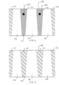
- Screen openings 26 may diverge downwardly between the upper surface 22 and the lower surface 24 and the first members 101 may be substantially in the shape of inverted trapezoids. See, e.g., Figures 6 and 7 .
- This general shape of the first members 101 prevents blinding in screens 10.
- first members 101 include reinforcement members 50.
- first members 101 do not include reinforcement members 50.
- Open screening areas may range, for example, from between about 40 percent to about 46 percent.
- the relatively large open screening areas may be obtained through the placement of bi-directional reinforcement members 50 in cross members (e.g., members 203, 204) as described in the various embodiments herein.
- the reinforcement members significantly decrease the size of both of the bi-directional support cross members and allow for a thinner screen members, 101, 102 forming the screen openings 26.
- the grid work of support members and reinforcement members provide for a structurally sound screen that maintains the necessary screen openings during vibratory operation.
- Third and fourth members 203, 204 may have a thickness greater than the first and second members 101, 102 and may have a portion 210 extending downwardly below the lower surface 24 of body 12. The greater thickness and portion extending downwardly may provide additional structural support to first and second members 101, 102. As shown in FIG. 1B , portion 210 may be substantially triangular in cross-section with apexes projecting away from the lower surface 24 of body 12.
- the third members 203 may be substantially parallel and extend transversely between the side edge portions 14, 16 and may have multiple first members 101 therebetween.
- the fourth members 204 may be substantially parallel and extend transversely between the lower edge portion 18 and the upper edge portion 20 and having multiple second members 102 therebetween. Fourth members 204 have reinforcement rods 1050 integrally molded therein.
- Reinforcement members 50 are molded integrally with the fourth members 204, and may be molded integrally with the third members 203. See, e.g., FIGS. 3A , 5A .
- Third and fourth members 203, 204 may be configured to have a minimal thickness through inclusion of reinforcement members 50, while providing the necessary structural support to maintain the screen openings 26 formed by first and second members 101, 102 during vibratory screening applications.
- the bi-direction support system provided by reinforced third and fourth members 203, 204 greatly reduces the thickness of the support members and provides for increased open screening area and overall screen efficiencies. Incorporation of reinforcement rods 1050 into fourth members 204 adds stability to screen 10 and prevents hourglassing, i.e., deflection inwardly of side edges 14, 16 to give the screen a general hourglass type shape.
- Fifth members 305 and sixth members 306 may be included in body 12. Fifth and sixth members may have a thickness greater than the third and fourth members and may have a portion 310 extending downwardly away from the lower surface of the body. The greater thickness and portion extending downwardly may to provide additional structural support to first and second members 101, 102.
- the sixth members 306 may include a portion 320 extending upwardly away from the upper surface of the body. Portion 320 may be substantially triangular in cross-section with apexes projecting away from the upper surface 22 of body 12. Sixth members 306 are shown in FIG. 2 with portion 320 extending upwardly away from the upper surface of body 12 and acting as flow guides. Sixth members 306 may have reinforcement rods 1050 integrally molded therein.
- the fifth members 305 may be substantially parallel and extending transversely between the side edge portions 14, 16 and have multiple third members 203 therebetween.
- the sixth members 306 may be substantially parallel and extending transversely between the lower edge portion 18 and the upper edge portion 20 and have multiple fourth members 204 therebetween.
- Reinforcement members 50 may be molded integrally with fifth and sixth members 305, 306.
- Fifth and sixth members 305, 306 may be provided for additional support to screen openings 26 and may be configured to have a minimal thickness through inclusion of reinforcement members 50, while providing the necessary structural support to maintain screen openings 26 during vibratory screening applications.
- the bi-direction support system provided by reinforced fifth and sixth members 305, 306 greatly reduces the thickness of the support members and provides for increased open screening area and overall screen efficiencies. Incorporation of reinforcement rods 1050 into sixth members 306 adds stability to screen 10 and prevents hourglassing.
- FIG. 1A shows an exemplary embodiment of the present inventions having first and second members 101, 102 forming screen openings 26 and members 203, 204 forming a support grid structure for openings 26.
- screen 10 does not include fifth and sixth members 305, 306.
- FIGS. 12 and 12A show another exemplary embodiment of the present invention having reinforcement rods 1050 integrally molded therein.
- reinforcement rods 1050 are integrally molded into fourth members 204.
- Reinforcement rods 1050 may also be integrally molded into sixth members 306 or other members running parallel to members 204 and 306.
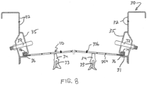
- the vibratory screen 10 is mounted on a vibratory screening machine 30 ( FIG. 8 ) in the well known manner. More specifically, it is mounted on the screen deck bed 31 which is mounted on the frame (not shown) of the machine.
- the screen deck bed 31 includes spaced substantially parallel frame members 32 secured to each other by spaced substantially parallel cross frame members (not shown). Extending transversely between the cross frame members are a plurality of substantially parallel stringers 33 which mount channel rubbers 34.
- Mounted on parallel frame members 32 are channel-shaped draw bars 35 having lower portions 36 which are received within side edge portions 14, 16.
- Draw bolts 37 draw bars 35 apart to thereby tension vibratory screen 10 with the required force.
- the foregoing type of screen deck bed is well known in the art. Screen 10 may be mounted to other vibratory screening machines and side edge portions 14, 16 may be configured in other shapes to accommodate different vibratory screening machines.
- FIG. 13 is mounted front to back on vibratory screening machine 1010.
- angle 15 is included in upper edge 20 and lower edge 18 and is below top surface 22.
- This embodiment has tension applied from underneath the screen rather than above and the tension is applied from front to back.
- FIG. 14 shows an embodiment having angle 15 included in side edges 18, 20 . This embodiment also has tension applied from above the screen and from side to side.
- Reinforcement members 50 as described herein may be an aramid fiber (or individual filaments thereof), a naturally occurring fiber or others material having relatively large tensile strengths with relatively small cross sectional areas.
- an aramid fiber is used as reinforcement fiber 50 it may be aramid fibers that are commercially obtainable under the trademark KEVLAR of the DuPont Company and further identified by the designation KEVLAR 29.
- the reinforcement members 50 may also be at least one of aramid fibers that are commercially obtainable under the trademarks TWARON, SULFRON, TEIJINCONEX, and TECHNORA of the Teijin Company.
- the aramid fibers may be twisted or woven multistrand so that they act as nature of wicks to absorb the polyurethane which is molded around them to thereby provide an extremely good bond therewith.
- the twisted or a woven multistrand fibers may be about 55 denier to about 2840 denier, preferably approximately 1500 denier.
- the flexibility of the aramid fibers provides a flexible reinforcement system for the molded polyurethane which is able to return to its original molded shape after the necessary bending and flexing that occurs during handling and installation into the vibratory frame member 32.
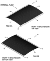
- flexible aramid fibers permit the flexible polyurethane screen to be flexed without harm into an arcuate condition and tensioned as shown in FIGS. 8 , 13 and 14 .
- Reinforcement members 50 may be tensioned before polyurethane is molded around them.
- Various configurations of reinforcement members 50 may be provided in any one of the first, second, third, fourth, fifth and sixth members 101, 102, 203, 204, 305, 306.
- Each member may include zero, one or more reinforcement members 50 and the reinforcement members 50 may be of different sizes and materials.
- Reinforcement members 50 may be located in the bottom halves of the members so as not to be exposed relatively early as the upper surface of the screen wears.
- first members 101 will vibrate to enhance the screening action.
- first members 101 are flexible and relatively thin they will provide a relatively high amplitude of desirable vibration.
- the reason the first members 101 can be made relatively thin, creating screen openings described herein, is because of a support framework of bi-directional support members and reinforcement members, as described herein, having relatively large tensile strengths with relatively small cross sectional areas. The making of the support members and the first members 101 relatively thin results in the screen having a greater percentage of open area, which, in turn, increases its capacity.
- a vibratory screen 10 includes a flexible molded polyurethane body 12 having substantially parallel side edge portions 14, 16 at opposite ends of body 12, a lower edge portion 18 substantially perpendicular to the side edge portions 14, 16, an upper edge portion 20 substantially perpendicular to the side edge portions 14, 16 and opposite the lower edge portion 18, an upper surface 22, a lower surface 24, first and second members 101, 102 forming screening openings 26, the first members 101 extending between the side edge portions 14, 16 and the second members 102 extending between the lower edge portion 18 and the upper edge portion 20.
- the body also includes third and fourth members 203, 204. Third and fourth members 203 and 204 may have a thickness greater than the first and second members 101, 102.
- Third members 203 are substantially parallel and extend transversely between the side edge portions 14, 16 and have multiple first members 101 therebetween.
- Fourth members 204 are substantially parallel and extend transversely between the lower edge portion 18 and the upper edge portion 20 and have multiple second members 102 therebetween.
- Reinforcement members 50 may be molded integrally with the third members 203 and are molded integrally with the fourth members 204.
- Reinforcement rods 1050 are molded integrally with fourth members 204.
- the body also includes fifth and sixth members 305, 306.
- Fifth members 305 are substantially parallel and extending transversely between the side edge portions 14, 16.
- Sixth members 306 are substantially parallel and extending transversely between the lower edge portion 18 and the upper edge portion 20.
- the fifth and sixth members have a thickness greater than the third and fourth members and include reinforcement members 50 molded integrally therewith.
- Reinforcement rods 1050 may be molded integrally with the sixth members 306. Vibratory screens according to this configuration may have open screening areas greater than forty percent and mesh sizes ranging from approximate .375 mesh to approximately 400 mesh.
- screens tested having the aforementioned configuration include a 43 mesh size screen, a 140 mesh size screen and a 210 mesh size screen.
- Each of these screens had open screening areas of approximately 40 percent to approximately 46 percent.
- Such large screening areas for such fine mesh sizes are achieve through the relatively strong and thin grid framework created by the third, fourth, fifth and sixth members, 203, 204, 305, 306 and reinforcement members molded integrally therewith.
- the size of each grid unit formed by the intersection of the third and fourth members, 203 and 204 is approximately 2.54cm by 2.54cm (1" by 1").
- grid units may be larger for screens with larger screen openings and grid units are smaller for screens with smaller screen openings. This principle may be generally applicable for each example embodiment discussed herein.
- Grid units may also have a generally rectangular shape or any other suitable shape for supporting the screen openings.
- a method of making a vibratory screen according to the wording of claim 12 is disclosed.
Landscapes
- Combined Means For Separation Of Solids (AREA)
- Processing And Handling Of Plastics And Other Materials For Molding In General (AREA)
- Vibration Prevention Devices (AREA)
Claims (12)
- Tamis vibratoire (10), comprenant : un corps en polyuréthane moulé flexible (12) présentant des parties de bord latéral sensiblement parallèles (14, 16) à des extrémités opposées du corps (12), une partie de bord inférieur (18) sensiblement perpendiculaire aux parties de bord latéral (14, 16), une partie de bord supérieur (20) sensiblement perpendiculaire aux parties de bord latéral (14, 16) et opposée à la partie de bord inférieur (18), une surface supérieure (22), une surface inférieure (24), des premiers et deuxièmes éléments (101, 102) formant des ouvertures de tamisage (26), les premiers éléments (101) s'étendant entre les parties de bord latéral (14, 16) et les deuxièmes éléments (102) s'étendant entre la partie de bord inférieur (18) et la partie de bord supérieur (20), des troisième et quatrième éléments (203, 204), les troisièmes éléments (203) étant sensiblement parallèles à et s'étendant transversalement entre les parties de bord latéral (14, 16) et présentant entre eux de multiples premiers éléments (101), les quatrièmes éléments (204) étant sensiblement parallèles à et s'étendant transversalement entre la partie de bord inférieur et la partie de bord supérieur et présentant entre eux de multiples deuxièmes éléments (102), des éléments de renforcement (50) moulés d'un seul tenant avec au moins certains des premiers et deuxièmes éléments (101, 102) et facultativement avec le troisième élément (103), et moulés d'un seul tenant avec le quatrième élément (204), et caractérisé par des tiges de renforcement (1050) moulées d'un seul tenant avec les quatrièmes éléments (204).
- Tamis vibratoire (10) selon la revendication 1, dans lequel les ouvertures sont d'environ 0,044 mm à environ 4 mm entre des surfaces intérieures des premiers éléments (101) et d'environ 0,088 mm à environ 60 mm entre des surfaces intérieures des deuxièmes éléments (102).
- Tamis vibratoire (10) selon la revendication 1, dans lequel les parties de bord latéral (14, 16) sont formées selon des configurations en forme de U.
- Tamis vibratoire selon la revendication 1, dans lequel la partie de bord supérieure (20) et la partie de bord inférieure (18) sont formées selon des configurations en forme de U.
- Tamis vibratoire selon la revendication 1, dans lequel les éléments de renforcement (50) sont au moins une fibre parmi une fibre d'aramide et une fibre naturelle.
- Tamis vibratoire selon la revendication 5, dans lequel le premier élément de renforcement (50) est une fibre d'aramide qui est au moins l'un d'un multibrin torsadé et d'un multibrin tissé et dans lequel le polyuréthane imprègne le multibrin en formant une liaison entre le premier élément et la fibre en son sein et une liaison entre le deuxième élément et la fibre en son sein.
- Tamis vibratoire selon la revendication 5, dans lequel l'élément de renforcement (50) est une fibre d'aramide qui est au moins un parmi un multibrin torsadé et un multibrin tissé, dans lequel les fibres sont d'environ 55 deniers à environ 2 840 deniers.
- Tamis vibratoire selon la revendication 1, dans lequel les parties de bord latéral (14, 16) incluent un élément coulé.
- Tamis vibratoire selon la revendication 1, dans lequel la partie de bord supérieure (20) et la partie de bord inférieure (18) incluent un élément coulé.
- Tamis vibratoire selon la revendication 1, dans lequel le tamis vibratoire (10) présente une surface de tamisage ouverte supérieure à quarante pour cent.
- Tamis vibratoire (10) selon la revendication 1, dans lequel les tiges de renforcement (1050) sont au moins l'un d'un plastique, d'un métal et d'un polymère.
- Procédé de fabrication d'un tamis vibratoire (10), comprenant les étapes consistant à :créer un moule configuré pour fabriquer le tamis vibratoire (10), le tamis vibratoire présentant un corps en polyuréthane moulé flexible ;installer des éléments de renforcement (50) dans le moule, les éléments de renforcement (50) étant configurés pour être moulés d'un seul tenant avec le corps (12) ;installer des tiges de renforcement (1050) dans le moule, les tiges de renforcement (1050) étant configurées pour être moulées d'un seul tenant avec le corps (12) remplissant le moule de polyuréthane ; etformer le tamis vibratoire (10), le tamis vibratoire (10) présentant des parties de bord latéral sensiblement parallèles (14, 16) à des extrémités opposées du corps (12), une partie de bord inférieur (18) sensiblement perpendiculaire aux parties de bord latéral (14, 16), une partie de bord supérieur (20) sensiblement perpendiculaire aux parties de bord latéral (14, 16) et opposée à la partie de bord inférieur (18), une surface supérieure (22), une surface inférieure (24), des premiers et deuxième éléments (101, 102) formant des ouvertures de tamisage, les premiers éléments (101) s'étendant entre les parties de bord latéral (14, 16) et les deuxièmes éléments (102) s'étendant entre la partie de bord inférieur (18) et la partie de bord supérieur (20), des troisièmes éléments (203) sensiblement parallèles et présentant entre eux de multiples premiers éléments (101), des quatrièmes éléments (204) sensiblement parallèles et présentant entre eux de multiples deuxièmes éléments (102), des éléments de renforcement moulés d'un seul tenant avec au moins certains des premiers et deuxièmes éléments (101, 102) et facultativement avec le troisième élément (103), et moulés d'un seul tenant avec le quatrième élément (204), et caractérisé par des tiges de renforcement (1050) moulées d'un seul tenant avec les quatrièmes éléments (204).
Priority Applications (1)
| Application Number | Priority Date | Filing Date | Title |
|---|---|---|---|
| EP23157742.0A EP4219027A3 (fr) | 2013-03-15 | 2014-02-28 | Tamis vibrant en polyurethane |
Applications Claiming Priority (2)
| Application Number | Priority Date | Filing Date | Title |
|---|---|---|---|
| US13/838,968 US9010539B2 (en) | 2010-04-19 | 2013-03-15 | Polyurethane vibratory screen |
| PCT/US2014/019233 WO2014149516A1 (fr) | 2013-03-15 | 2014-02-28 | Tamis vibratoire en polyuréthane |
Related Child Applications (2)
| Application Number | Title | Priority Date | Filing Date |
|---|---|---|---|
| EP23157742.0A Division EP4219027A3 (fr) | 2013-03-15 | 2014-02-28 | Tamis vibrant en polyurethane |
| EP23157742.0A Division-Into EP4219027A3 (fr) | 2013-03-15 | 2014-02-28 | Tamis vibrant en polyurethane |
Publications (2)
| Publication Number | Publication Date |
|---|---|
| EP2969265A1 EP2969265A1 (fr) | 2016-01-20 |
| EP2969265B1 true EP2969265B1 (fr) | 2023-03-29 |
Family
ID=50342501
Family Applications (2)
| Application Number | Title | Priority Date | Filing Date |
|---|---|---|---|
| EP14711661.0A Active EP2969265B1 (fr) | 2013-03-15 | 2014-02-28 | Tamis vibratoire en polyuréthane |
| EP23157742.0A Withdrawn EP4219027A3 (fr) | 2013-03-15 | 2014-02-28 | Tamis vibrant en polyurethane |
Family Applications After (1)
| Application Number | Title | Priority Date | Filing Date |
|---|---|---|---|
| EP23157742.0A Withdrawn EP4219027A3 (fr) | 2013-03-15 | 2014-02-28 | Tamis vibrant en polyurethane |
Country Status (17)
| Country | Link |
|---|---|
| EP (2) | EP2969265B1 (fr) |
| KR (3) | KR102098368B1 (fr) |
| CN (1) | CN105246602B (fr) |
| AU (1) | AU2014238144C1 (fr) |
| BR (2) | BR112015023789B1 (fr) |
| CA (1) | CA2902782C (fr) |
| CL (1) | CL2015002761A1 (fr) |
| EA (2) | EA202091026A1 (fr) |
| EC (1) | ECSP15042931A (fr) |
| HK (1) | HK1218097A1 (fr) |
| MX (2) | MX366884B (fr) |
| NZ (1) | NZ712824A (fr) |
| PE (1) | PE20151985A1 (fr) |
| TN (1) | TN2015000405A1 (fr) |
| UA (1) | UA117240C2 (fr) |
| WO (1) | WO2014149516A1 (fr) |
| ZA (1) | ZA201506226B (fr) |
Families Citing this family (10)
| Publication number | Priority date | Publication date | Assignee | Title |
|---|---|---|---|---|
| US9409209B2 (en) | 2012-05-25 | 2016-08-09 | Derrick Corporation | Injection molded screening apparatuses and methods |
| US11161150B2 (en) | 2012-05-25 | 2021-11-02 | Derrick Corporation | Injection molded screening apparatuses and methods |
| US10576502B2 (en) | 2012-05-25 | 2020-03-03 | Derrick Corporation | Injection molded screening apparatuses and methods |
| MY197340A (en) | 2012-05-25 | 2023-06-14 | Derrick Corp | Injection molded screening apparatuses and methods |
| US11505638B2 (en) | 2017-04-28 | 2022-11-22 | Derrick Corporation | Thermoplastic compositions, methods, apparatus, and uses |
| AU2018260541A1 (en) | 2017-04-28 | 2019-11-07 | Derrick Corporation | Thermoplastic compositions, methods, apparatus, and uses |
| US11213857B2 (en) | 2017-06-06 | 2022-01-04 | Derrick Corporation | Method and apparatus for screening |
| WO2018226878A1 (fr) * | 2017-06-06 | 2018-12-13 | Derrick Corporation | Procédé et appareils de tamisage |
| KR102432288B1 (ko) * | 2022-01-21 | 2022-08-12 | 주식회사 대신폴리텍 | 내열용 선별망, 내열용 선별망 제조장치 및 제조방법 |
| EP4504430A4 (fr) | 2022-04-06 | 2025-08-27 | Derrick Corp | Appareils et procédés de criblage moulés par injection |
Family Cites Families (6)
| Publication number | Priority date | Publication date | Assignee | Title |
|---|---|---|---|---|
| ZA774472B (en) * | 1977-07-25 | 1979-06-27 | Herrmann Screens Mfg Co Ltd | Improvements in or relating to screening apparatus |
| US4819809A (en) | 1985-09-09 | 1989-04-11 | Derrick Manufacturing Corporation | Reinforced polyurethane vibratory screen |
| US4857176A (en) * | 1986-08-04 | 1989-08-15 | Derrick Manufacturing Corporation | Reinforced molded polyurethane vibratory screen |
| US7264125B2 (en) * | 2003-04-23 | 2007-09-04 | Derrick Corporation | Undulating molded plastic vibratory screen |
| CN100512984C (zh) * | 2007-07-03 | 2009-07-15 | 北京航空航天大学 | 一种纤维增强聚氨酯精细筛网及其成型方法 |
| US8584866B2 (en) * | 2010-04-19 | 2013-11-19 | Derrick Corporation | Polyurethane vibratory screen |
-
2014
- 2014-02-28 PE PE2015002023A patent/PE20151985A1/es unknown
- 2014-02-28 EP EP14711661.0A patent/EP2969265B1/fr active Active
- 2014-02-28 KR KR1020177030859A patent/KR102098368B1/ko active Active
- 2014-02-28 WO PCT/US2014/019233 patent/WO2014149516A1/fr not_active Ceased
- 2014-02-28 BR BR112015023789-4A patent/BR112015023789B1/pt active IP Right Grant
- 2014-02-28 AU AU2014238144A patent/AU2014238144C1/en active Active
- 2014-02-28 HK HK16106123.9A patent/HK1218097A1/zh unknown
- 2014-02-28 CN CN201480015525.0A patent/CN105246602B/zh active Active
- 2014-02-28 MX MX2015012839A patent/MX366884B/es active IP Right Grant
- 2014-02-28 EA EA202091026A patent/EA202091026A1/ru unknown
- 2014-02-28 CA CA2902782A patent/CA2902782C/fr active Active
- 2014-02-28 KR KR1020157027068A patent/KR20150127141A/ko not_active Ceased
- 2014-02-28 NZ NZ712824A patent/NZ712824A/en not_active IP Right Cessation
- 2014-02-28 EA EA201591502A patent/EA035616B1/ru unknown
- 2014-02-28 EP EP23157742.0A patent/EP4219027A3/fr not_active Withdrawn
- 2014-02-28 KR KR1020197037247A patent/KR102211164B1/ko not_active Expired - Fee Related
- 2014-02-28 UA UAA201509651A patent/UA117240C2/uk unknown
-
2015
- 2015-08-26 ZA ZA2015/06226A patent/ZA201506226B/en unknown
- 2015-09-09 TN TN2015000405A patent/TN2015000405A1/en unknown
- 2015-09-14 MX MX2019008909A patent/MX2019008909A/es unknown
- 2015-09-15 CL CL2015002761A patent/CL2015002761A1/es unknown
- 2015-10-12 EC ECIEPI201542931A patent/ECSP15042931A/es unknown
-
2020
- 2020-10-26 BR BR132020021868A patent/BR132020021868E2/pt active IP Right Grant
Also Published As
Similar Documents
| Publication | Publication Date | Title |
|---|---|---|
| US9010539B2 (en) | Polyurethane vibratory screen | |
| US9375756B2 (en) | Polyurethane vibratory screen | |
| EP2969265B1 (fr) | Tamis vibratoire en polyuréthane | |
| CA2796724C (fr) | Tamis vibrant en polyurethane | |
| US9403192B2 (en) | Polyurethane screen | |
| CA2980274C (fr) | Tamis en polyurethane | |
| AU2015200737B2 (en) | Polyurethane vibratory screen | |
| HK1231009A1 (en) | Polyurethane vibratory screen | |
| HK1180638B (en) | Polyurethane vibratory screen | |
| EA042522B1 (ru) | Полиуретановое вибрационное сито |
Legal Events
| Date | Code | Title | Description |
|---|---|---|---|
| PUAI | Public reference made under article 153(3) epc to a published international application that has entered the european phase |
Free format text: ORIGINAL CODE: 0009012 |
|
| 17P | Request for examination filed |
Effective date: 20150824 |
|
| AK | Designated contracting states |
Kind code of ref document: A1 Designated state(s): AL AT BE BG CH CY CZ DE DK EE ES FI FR GB GR HR HU IE IS IT LI LT LU LV MC MK MT NL NO PL PT RO RS SE SI SK SM TR |
|
| AX | Request for extension of the european patent |
Extension state: BA ME |
|
| RIN1 | Information on inventor provided before grant (corrected) |
Inventor name: COLGROVE, JAMES R. Inventor name: LIPA, ANTHONY J. |
|
| DAX | Request for extension of the european patent (deleted) | ||
| REG | Reference to a national code |
Ref country code: HK Ref legal event code: DE Ref document number: 1218097 Country of ref document: HK |
|
| STAA | Information on the status of an ep patent application or granted ep patent |
Free format text: STATUS: EXAMINATION IS IN PROGRESS |
|
| 17Q | First examination report despatched |
Effective date: 20181030 |
|
| REG | Reference to a national code |
Ref country code: HK Ref legal event code: WD Ref document number: 1218097 Country of ref document: HK |
|
| GRAP | Despatch of communication of intention to grant a patent |
Free format text: ORIGINAL CODE: EPIDOSNIGR1 |
|
| STAA | Information on the status of an ep patent application or granted ep patent |
Free format text: STATUS: GRANT OF PATENT IS INTENDED |
|
| INTG | Intention to grant announced |
Effective date: 20221017 |
|
| GRAS | Grant fee paid |
Free format text: ORIGINAL CODE: EPIDOSNIGR3 |
|
| GRAA | (expected) grant |
Free format text: ORIGINAL CODE: 0009210 |
|
| STAA | Information on the status of an ep patent application or granted ep patent |
Free format text: STATUS: THE PATENT HAS BEEN GRANTED |
|
| AK | Designated contracting states |
Kind code of ref document: B1 Designated state(s): AL AT BE BG CH CY CZ DE DK EE ES FI FR GB GR HR HU IE IS IT LI LT LU LV MC MK MT NL NO PL PT RO RS SE SI SK SM TR |
|
| REG | Reference to a national code |
Ref country code: GB Ref legal event code: FG4D |
|
| REG | Reference to a national code |
Ref country code: CH Ref legal event code: EP |
|
| REG | Reference to a national code |
Ref country code: DE Ref legal event code: R096 Ref document number: 602014086543 Country of ref document: DE |
|
| REG | Reference to a national code |
Ref country code: AT Ref legal event code: REF Ref document number: 1556301 Country of ref document: AT Kind code of ref document: T Effective date: 20230415 |
|
| REG | Reference to a national code |
Ref country code: IE Ref legal event code: FG4D |
|
| REG | Reference to a national code |
Ref country code: LT Ref legal event code: MG9D |
|
| PG25 | Lapsed in a contracting state [announced via postgrant information from national office to epo] |
Ref country code: RS Free format text: LAPSE BECAUSE OF FAILURE TO SUBMIT A TRANSLATION OF THE DESCRIPTION OR TO PAY THE FEE WITHIN THE PRESCRIBED TIME-LIMIT Effective date: 20230329 Ref country code: NO Free format text: LAPSE BECAUSE OF FAILURE TO SUBMIT A TRANSLATION OF THE DESCRIPTION OR TO PAY THE FEE WITHIN THE PRESCRIBED TIME-LIMIT Effective date: 20230629 Ref country code: LV Free format text: LAPSE BECAUSE OF FAILURE TO SUBMIT A TRANSLATION OF THE DESCRIPTION OR TO PAY THE FEE WITHIN THE PRESCRIBED TIME-LIMIT Effective date: 20230329 Ref country code: LT Free format text: LAPSE BECAUSE OF FAILURE TO SUBMIT A TRANSLATION OF THE DESCRIPTION OR TO PAY THE FEE WITHIN THE PRESCRIBED TIME-LIMIT Effective date: 20230329 Ref country code: HR Free format text: LAPSE BECAUSE OF FAILURE TO SUBMIT A TRANSLATION OF THE DESCRIPTION OR TO PAY THE FEE WITHIN THE PRESCRIBED TIME-LIMIT Effective date: 20230329 |
|
| REG | Reference to a national code |
Ref country code: NL Ref legal event code: MP Effective date: 20230329 |
|
| REG | Reference to a national code |
Ref country code: AT Ref legal event code: MK05 Ref document number: 1556301 Country of ref document: AT Kind code of ref document: T Effective date: 20230329 |
|
| PG25 | Lapsed in a contracting state [announced via postgrant information from national office to epo] |
Ref country code: SE Free format text: LAPSE BECAUSE OF FAILURE TO SUBMIT A TRANSLATION OF THE DESCRIPTION OR TO PAY THE FEE WITHIN THE PRESCRIBED TIME-LIMIT Effective date: 20230329 Ref country code: NL Free format text: LAPSE BECAUSE OF FAILURE TO SUBMIT A TRANSLATION OF THE DESCRIPTION OR TO PAY THE FEE WITHIN THE PRESCRIBED TIME-LIMIT Effective date: 20230329 Ref country code: GR Free format text: LAPSE BECAUSE OF FAILURE TO SUBMIT A TRANSLATION OF THE DESCRIPTION OR TO PAY THE FEE WITHIN THE PRESCRIBED TIME-LIMIT Effective date: 20230630 Ref country code: FI Free format text: LAPSE BECAUSE OF FAILURE TO SUBMIT A TRANSLATION OF THE DESCRIPTION OR TO PAY THE FEE WITHIN THE PRESCRIBED TIME-LIMIT Effective date: 20230329 |
|
| PG25 | Lapsed in a contracting state [announced via postgrant information from national office to epo] |
Ref country code: SM Free format text: LAPSE BECAUSE OF FAILURE TO SUBMIT A TRANSLATION OF THE DESCRIPTION OR TO PAY THE FEE WITHIN THE PRESCRIBED TIME-LIMIT Effective date: 20230329 Ref country code: RO Free format text: LAPSE BECAUSE OF FAILURE TO SUBMIT A TRANSLATION OF THE DESCRIPTION OR TO PAY THE FEE WITHIN THE PRESCRIBED TIME-LIMIT Effective date: 20230329 Ref country code: PT Free format text: LAPSE BECAUSE OF FAILURE TO SUBMIT A TRANSLATION OF THE DESCRIPTION OR TO PAY THE FEE WITHIN THE PRESCRIBED TIME-LIMIT Effective date: 20230731 Ref country code: ES Free format text: LAPSE BECAUSE OF FAILURE TO SUBMIT A TRANSLATION OF THE DESCRIPTION OR TO PAY THE FEE WITHIN THE PRESCRIBED TIME-LIMIT Effective date: 20230329 Ref country code: EE Free format text: LAPSE BECAUSE OF FAILURE TO SUBMIT A TRANSLATION OF THE DESCRIPTION OR TO PAY THE FEE WITHIN THE PRESCRIBED TIME-LIMIT Effective date: 20230329 Ref country code: AT Free format text: LAPSE BECAUSE OF FAILURE TO SUBMIT A TRANSLATION OF THE DESCRIPTION OR TO PAY THE FEE WITHIN THE PRESCRIBED TIME-LIMIT Effective date: 20230329 |
|
| PG25 | Lapsed in a contracting state [announced via postgrant information from national office to epo] |
Ref country code: SK Free format text: LAPSE BECAUSE OF FAILURE TO SUBMIT A TRANSLATION OF THE DESCRIPTION OR TO PAY THE FEE WITHIN THE PRESCRIBED TIME-LIMIT Effective date: 20230329 Ref country code: PL Free format text: LAPSE BECAUSE OF FAILURE TO SUBMIT A TRANSLATION OF THE DESCRIPTION OR TO PAY THE FEE WITHIN THE PRESCRIBED TIME-LIMIT Effective date: 20230329 Ref country code: IS Free format text: LAPSE BECAUSE OF FAILURE TO SUBMIT A TRANSLATION OF THE DESCRIPTION OR TO PAY THE FEE WITHIN THE PRESCRIBED TIME-LIMIT Effective date: 20230729 |
|
| REG | Reference to a national code |
Ref country code: DE Ref legal event code: R097 Ref document number: 602014086543 Country of ref document: DE |
|
| PG25 | Lapsed in a contracting state [announced via postgrant information from national office to epo] |
Ref country code: DK Free format text: LAPSE BECAUSE OF FAILURE TO SUBMIT A TRANSLATION OF THE DESCRIPTION OR TO PAY THE FEE WITHIN THE PRESCRIBED TIME-LIMIT Effective date: 20230329 Ref country code: CZ Free format text: LAPSE BECAUSE OF FAILURE TO SUBMIT A TRANSLATION OF THE DESCRIPTION OR TO PAY THE FEE WITHIN THE PRESCRIBED TIME-LIMIT Effective date: 20230329 |
|
| PLBE | No opposition filed within time limit |
Free format text: ORIGINAL CODE: 0009261 |
|
| STAA | Information on the status of an ep patent application or granted ep patent |
Free format text: STATUS: NO OPPOSITION FILED WITHIN TIME LIMIT |
|
| 26N | No opposition filed |
Effective date: 20240103 |
|
| PG25 | Lapsed in a contracting state [announced via postgrant information from national office to epo] |
Ref country code: SI Free format text: LAPSE BECAUSE OF FAILURE TO SUBMIT A TRANSLATION OF THE DESCRIPTION OR TO PAY THE FEE WITHIN THE PRESCRIBED TIME-LIMIT Effective date: 20230329 |
|
| PG25 | Lapsed in a contracting state [announced via postgrant information from national office to epo] |
Ref country code: SI Free format text: LAPSE BECAUSE OF FAILURE TO SUBMIT A TRANSLATION OF THE DESCRIPTION OR TO PAY THE FEE WITHIN THE PRESCRIBED TIME-LIMIT Effective date: 20230329 Ref country code: IT Free format text: LAPSE BECAUSE OF FAILURE TO SUBMIT A TRANSLATION OF THE DESCRIPTION OR TO PAY THE FEE WITHIN THE PRESCRIBED TIME-LIMIT Effective date: 20230329 |
|
| REG | Reference to a national code |
Ref country code: DE Ref legal event code: R119 Ref document number: 602014086543 Country of ref document: DE |
|
| PG25 | Lapsed in a contracting state [announced via postgrant information from national office to epo] |
Ref country code: MC Free format text: LAPSE BECAUSE OF FAILURE TO SUBMIT A TRANSLATION OF THE DESCRIPTION OR TO PAY THE FEE WITHIN THE PRESCRIBED TIME-LIMIT Effective date: 20230329 |
|
| REG | Reference to a national code |
Ref country code: CH Ref legal event code: PL |
|
| PG25 | Lapsed in a contracting state [announced via postgrant information from national office to epo] |
Ref country code: LU Free format text: LAPSE BECAUSE OF NON-PAYMENT OF DUE FEES Effective date: 20240228 |
|
| PG25 | Lapsed in a contracting state [announced via postgrant information from national office to epo] |
Ref country code: CH Free format text: LAPSE BECAUSE OF NON-PAYMENT OF DUE FEES Effective date: 20240229 |
|
| GBPC | Gb: european patent ceased through non-payment of renewal fee |
Effective date: 20240228 |
|
| PG25 | Lapsed in a contracting state [announced via postgrant information from national office to epo] |
Ref country code: LU Free format text: LAPSE BECAUSE OF NON-PAYMENT OF DUE FEES Effective date: 20240228 Ref country code: CH Free format text: LAPSE BECAUSE OF NON-PAYMENT OF DUE FEES Effective date: 20240229 |
|
| PG25 | Lapsed in a contracting state [announced via postgrant information from national office to epo] |
Ref country code: BG Free format text: LAPSE BECAUSE OF FAILURE TO SUBMIT A TRANSLATION OF THE DESCRIPTION OR TO PAY THE FEE WITHIN THE PRESCRIBED TIME-LIMIT Effective date: 20230329 |
|
| PG25 | Lapsed in a contracting state [announced via postgrant information from national office to epo] |
Ref country code: BG Free format text: LAPSE BECAUSE OF FAILURE TO SUBMIT A TRANSLATION OF THE DESCRIPTION OR TO PAY THE FEE WITHIN THE PRESCRIBED TIME-LIMIT Effective date: 20230329 |
|
| REG | Reference to a national code |
Ref country code: BE Ref legal event code: MM Effective date: 20240229 |
|
| PG25 | Lapsed in a contracting state [announced via postgrant information from national office to epo] |
Ref country code: DE Free format text: LAPSE BECAUSE OF NON-PAYMENT OF DUE FEES Effective date: 20240903 |
|
| PG25 | Lapsed in a contracting state [announced via postgrant information from national office to epo] |
Ref country code: BE Free format text: LAPSE BECAUSE OF NON-PAYMENT OF DUE FEES Effective date: 20240229 |
|
| PG25 | Lapsed in a contracting state [announced via postgrant information from national office to epo] |
Ref country code: GB Free format text: LAPSE BECAUSE OF NON-PAYMENT OF DUE FEES Effective date: 20240228 |
|
| PG25 | Lapsed in a contracting state [announced via postgrant information from national office to epo] |
Ref country code: FR Free format text: LAPSE BECAUSE OF NON-PAYMENT OF DUE FEES Effective date: 20240229 |
|
| PG25 | Lapsed in a contracting state [announced via postgrant information from national office to epo] |
Ref country code: IE Free format text: LAPSE BECAUSE OF NON-PAYMENT OF DUE FEES Effective date: 20240228 |
|
| PG25 | Lapsed in a contracting state [announced via postgrant information from national office to epo] |
Ref country code: IE Free format text: LAPSE BECAUSE OF NON-PAYMENT OF DUE FEES Effective date: 20240228 Ref country code: GB Free format text: LAPSE BECAUSE OF NON-PAYMENT OF DUE FEES Effective date: 20240228 Ref country code: FR Free format text: LAPSE BECAUSE OF NON-PAYMENT OF DUE FEES Effective date: 20240229 Ref country code: DE Free format text: LAPSE BECAUSE OF NON-PAYMENT OF DUE FEES Effective date: 20240903 Ref country code: BE Free format text: LAPSE BECAUSE OF NON-PAYMENT OF DUE FEES Effective date: 20240229 |
|
| PG25 | Lapsed in a contracting state [announced via postgrant information from national office to epo] |
Ref country code: CY Free format text: LAPSE BECAUSE OF FAILURE TO SUBMIT A TRANSLATION OF THE DESCRIPTION OR TO PAY THE FEE WITHIN THE PRESCRIBED TIME-LIMIT; INVALID AB INITIO Effective date: 20140228 |
|
| PG25 | Lapsed in a contracting state [announced via postgrant information from national office to epo] |
Ref country code: HU Free format text: LAPSE BECAUSE OF FAILURE TO SUBMIT A TRANSLATION OF THE DESCRIPTION OR TO PAY THE FEE WITHIN THE PRESCRIBED TIME-LIMIT; INVALID AB INITIO Effective date: 20140228 |
|
| PGFP | Annual fee paid to national office [announced via postgrant information from national office to epo] |
Ref country code: TR Payment date: 20260127 Year of fee payment: 13 |